

SAMSUNG MM-S8 User Manual
Instruction Manual
MICRO COMPONENT
AUDIO SYSTEM
CD-R/RW PLAYBACK
MM-S8
GB
2
Safety Warnings
CLASS 1 LASER PRODUCT
This Compact Disc player is classified as a CLASS 1
LASER product.
Use of controls adjustments or performance of procedures
other than those specified herein may result in hazardous
radiation exposure.
CAUTION-INVISIBLE LASER RADIATION WHEN OPEN
AND INTER LOCKS DEFEATED, AVOID EXPOSURE TO
BEAM.
WARNING: TO REDUCE THE RISK OF FIRE OR
ELECTRIC SHOCK, DO NOT EXPOSE
THIS APPLIANCE TO RAIN OR MOISTURE.
CAUTION: TO PREVENT ELECTRIC SHOCK, MATCH
WIDE BLADE OF PLUG TO WIDE SLOT,
FULLY INSERT.
CAUTION:
TO REDUCE THE RISK OF ELECTRIC SHOCK,
DO NOT REMOVE REAR COVER, NO USER
SERVICEABLE PARTS INSIDE, REFER SERVICING TO QUALIFIED SERVICE
PERSONNEL.
RISK OF ELECTRIC SHOCK.
DO NOT OPEN
CAUTION
CLASS 1 LASER PRODUCT
KLASSE 1 LASER PRODUKT
LUOKAN 1 LASER LAITE
KLASS 1 LASER APPARAT
PRODUCTO LASER CLASE 1
This symbol indicates that dangerous voltage constituting of a risk of electric shock is present within
this unit.
Wiring the Mains Power Supply Plug(UK Only)
IMPORTANT NOTICE
The mains lead on this equipment is supplied with a moulded plug incorporating a fuse. The value of the fuse is indicated on the pin face
of the plug and, if it requires replacing, a fuse approved to BS1362 of the same rating must be used.
Never use the plug with the fuse cover omitted. If the cover is detachable. If a replacement fuse cover is required, it must be of the same
colour as the pin face of the plug. Replacement covers are available from your dealer.
If the fitted plug is not suitable for the power points in your house or the cable is not long enough to reach a power point, you should obtain
a suitable safety approved extension lead or consult your dealer for assistance.
However, if there is no alternative to cutting off the plug, remove the fuse and then safely dispose of the plug. Do NOT connect the plug to
a mains socket as there is a risk of shock hazard from the bared flexible cord.
IMPORTANT
The wires in the mains lead are coloured in accordance with the following code:–
BLUE = NEUTRAL BROWN = LIVE
As these colours may not correspond to the coloured markings identifying the terminals in your plug, proceed as follows:–
The wire coloured BLUE must be connected to the terminal marked with the letter N or coloured BLUE or BLACK. The wire coloured
BROWN must be connected to the terminal marked with the letter L or coloured BROWN or RED.
WARNING: DO NOT CONNECT EITHER WIRE TO THE EARTH TERMINAL WHICH IS MARKED WITH THE LETTER E OR BY
THE EARTH SYMBOL , OR COLOURED GREEN OR GREEN AND YELLOW.
This symbol indicates that there are important operating and maintenance instructions in the owners
manual accompanying this unit.

GB
Press Push Important Note
Symbols
3
Contents
Thank you for buying this
SAMSUNG micro component system.
Please take time to read these instructions.
They will allow you to operate your
system with ease and take full advantage
of its features.
S
AFETY
W
ARNINGS
.................................................................................................................................................................................. 2
I
NSTALLING
Y
OURMICROCOMPONENTSYSTEM
Front Panel View........................................................................................................................................................................................4
Remote Control ..........................................................................................................................................................................................5
Rear Panel View ........................................................................................................................................................................................6
Where to Install Your Micro Component System ......................................................................................................................................7
Connecting your System to the Power Supply ..........................................................................................................................................7
Inserting Remote Control Batteries............................................................................................................................................................7
Connecting to an External Source ............................................................................................................................................................8
CD Digital Out Jack
..................................................................................................................................................................................8
Speaker Connection
............................................................................................................................................................8
Connecting the AM (MW)/LW Aerial..........................................................................................................................................................9
Connecting the FM Aerial ..........................................................................................................................................................................9
DEMO Function........................................................................................................................................................................................10
DIMMER Function....................................................................................................................................................................................10
Setting the Clock......................................................................................................................................................................................10
CD-P
LAYER
Listening to a Compact Disc
....................................................................................................................................................................11
Selecting a Track ....................................................................................................................................................................................11
Searching for a Specific Music Passage on a CD ..................................................................................................................................11
Function to skip through 10 tracks at a time................................................................................... .........................................................12
Repeating One or All Tracks on the Compact Discs ..............................................................................................................................12
REPEAT A↔B Function ..........................................................................................................................................................................12
Programming the Order of Playback........................................................................................................................................................13
Checking or Changing Programmed Tracks ..........................................................................................................................................13
T
UNER
Searching for and Storing the Radio Stations..........................................................................................................................................14
Selecting a Stored Station........................................................................................................................................................................14
Improving Radio Reception
......................................................................................................................................................................14
About RDS broadcasting..........................................................................................................................................................................15
About RDS DISPLAY function ................................................................................................................................................................15
PTY (Program Type) indication and PTY-SEARCH function ..................................................................................................................16
T
APEDECK
Listening to a Cassette ............................................................................................................................................................................17
Selecting the Cassette Playback Mode ..................................................................................................................................................17
Recording a Compact Disc ......................................................................................................................................................................18
Recording a Radio Program ....................................................................................................................................................................18
O
THERFUNCTIONS
Timer Function ........................................................................................................................................................................................19
Cancelling the Timer................................................................................................................................................................................19
EQ/S.BASS Function ..............................................................................................................................................................................20
SRS WOW Function ................................................................................................................................................................................20
Mute Function ..........................................................................................................................................................................................21
Setting the System to Switch off Automatically........................................................................................................................................21
Connecting Headphones..........................................................................................................................................................................21
R
ECOMMENDATIONS FORUSE
Safety Precautions ..................................................................................................................................................................................22
Cleaning Your Micro Component System ............................................................................................................................................22
Precautions When Using Compact Discs................................................................................................................................................23
Precautions When Using Audio Cassettes..............................................................................................................................................23
Before Contacting the After-Sales Service ..............................................................................................................................................23
Technical Specifications ..........................................................................................................................................................................24

GB
4
Front Panel View
1. FUNCTION (TUNER/CD/TAPE)
2.
POWER
(STANDBY/ON)
3.
DEMO/DIMMER
4. REVERSE MODE
5. CD SYNCHRONIZE / RECORD/PAUSE
6.
TUNING MODE
7.
HEADPHONE JACK CONNECTOR
8. SKIP OR SEARCH
9. DISC TRAY
10. CD DOOR OPEN/CLOSE
11. STOP
12. SRS WOW
13. AUX
14. VOLUME
15.
PUSH EJECT (CASSETTE DOOR
OPEN/CLOSE)
1
2
3
4
5
6
7
8
9
10
11
12
13
14
15
VOLUME
DEMO/
DIMMER
REV.MODE
CD SYNC.
PHONES
TUNER
Band
TAPE
TUNING
MODE
/DOWN UP/
CD
AUX
STOP
SRS WOW
OPEN/CLOSE

GB
5
Remote Control
1. PROGRAM/SET
2. POWER
3. TUNER/BAND
4. AUX
5. SLEEP
6. CD SYNC. / RECORD/PAUSE
7. SKIP OR SEARCH
8. CD STOP
9.
TUNING MODE/+10
10. TUNING UP OR DOWN
11. TAPE REWIND
12. TAPE STOP
13. TAPE PLAY
14. TAPE FAST-FORWARD
15. VOLUME CONTROL
16. REPEAT
17. CD PLAY/PAUSE
18. DISPLAY (RDS)
19. PTY (RDS)
20. SRS WOW
21. REPEAT A↔B / FM MONO/STEREO
22. TIMER ON/OFF
23. MUTE
24. EQ/SUPER BASS
25. TIMER/CLOCK
CD
TAPE
TUNER
BAND
MO/ST
TIMER/CLOCK TIMER ON/OFF
AUX
PROGRAM/SET REP. A B
SLEEP
EQ/S.BASS SRS WOW
TUNING
REPEAT
TUNING
MODE
VOLUME
MUTE
+10
CD SYNC.
DISPLAY
PTYRDS
1
2
3
4
5
6
7
8
9
10
11
12
25
24
23
22
21
20
19
18
17
16
15
14
13
GB
6
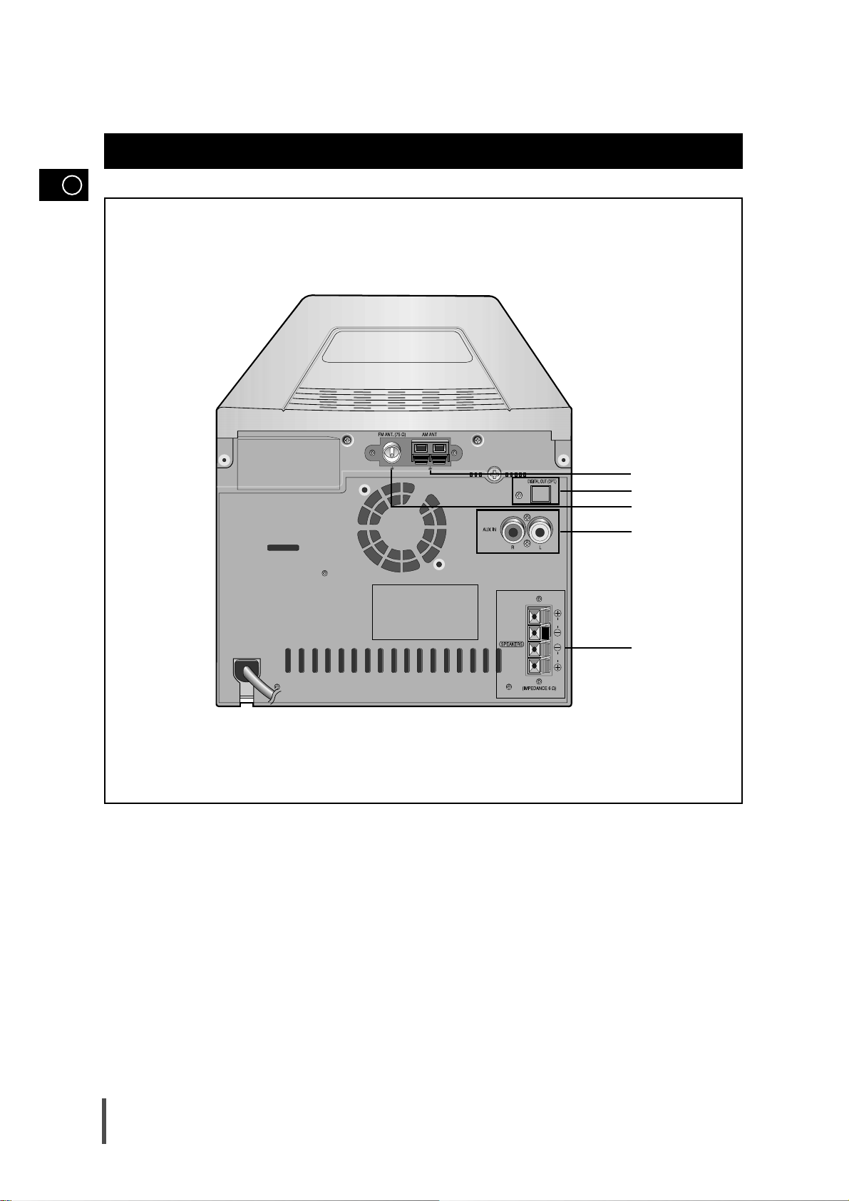
Rear Panel View
1. AM Aerial Connector Terminal
2. CD Digital Out jack
3. FM Aerial Connector Terminal
4. AUX-Input
5. Loudspeaker Connector Terminals
L
R
1
2
3
4
5

GB
7
The main lead must be plugged into an appropriate socket.
Before plugging your system into a main socket, you must check
the voltage.
Plug the main lead (marked AC Cord on the rear of the system) into
an appropriate socket.
Press the ( ) button to switch your micro component system on.
To take full advantage of your new micro component system,
follow these installation instructions before connecting the unit.
Install the system on a flat, stable surface.
Never place this unit on carpeting.
Never place this unit in an outdoor area.
Maintain an open space of approximately 6 inches (15 cm) on the
sides and rear of the system, for ventilation purposes.
Make sure that you have enough room to open the compact disc
compartment easily.
Place the loudspeakers at a reasonable distance on either side of
the system to ensure good stereo sound.
Direct the loudspeakers towards the listening area.
For optimum performance, make sure that both speakers are placed
at an equal distance above the floor.
Where to Install Your Micro Component System
Connecting your System to the Power Supply
2
Inserting Remote Control Batteries
Insert or replace remote control batteries when you:
Purchase the micro component system
Find that the remote control is no longer operating correctly
When replacing the batteries, use a new set of batteries and
never mix alkaline and manganese batteries.
Place your thumb on the position marked on the battery
compartment cover (rear of the remote control) and push the cover in
the direction of the arrow.
Insert two AAA, LR03 or equivalent batteries, taking care to respect
the polarities:
+ on the battery against + in the battery compartment
– on the battery against – in the battery compartment
Replace the cover by sliding it back until it clicks into position.
1
2
3
1
Volume
DEMO/
DIMMER
REV.MODE
CD SYNC.
PHONES
TUNER
Band
TAPE
TUNING
MODE
/DOWN UP/
CD
AUX
STOP
SRS WOW
OPEN/CLOSE
GB
8
The auxiliary input can be used to take advantage of the
sound quality of your micro component system when listening
to other sources.
Examples
: A television
A video disc player
A Hi-Fi stereo video cassette recorder
To connect the external source, the source must have an audio
output. In addition, you need an RCA connection cable.
Set the system to standby mode and disconnect it and the external
source from the main.
Connect the audio cable to the rear of the micro component system.
Connect the... To the connector marked...
Red jack R (right)
White jack L (left)
For optimum sound quality, do not invert the right and left
channels.
Plug the system back into the main socket and press ( ) to
switch it on.
Select the AUX source by pressing AUX.
Result: AUX is displayed.
Switch the external source on.
Example: You can watch a film and take advantage of stereo sound
provided that the original sound track is in stereo (as if you
were in a cinema).
Connecting to an External Source
1
2
3
4
5
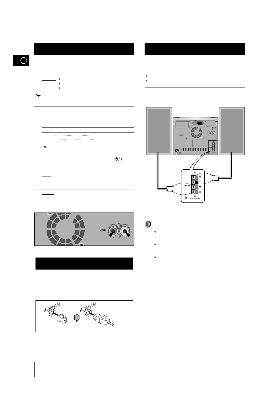
Speaker Connection
Directions in Installing Speaker
Installation in a place near heating apparatus, under direct lay of
light or with high humidity may cause performance degradation
of the speaker.
Do not install on the wall or on a high place of pole or other
unstable place to prevent any safety accident caused by falling
of the speaker.
Do not take the speaker apart from TV or computer monitor.
The speaker near the TV or computer monitor may influence the
quality of the screen display.
(Right Speaker) (Left Speaker)
This unit can output CD digital sound signals through this jack.
Use an optical cable to connect digital audio equipment.
(DAT deck, MD recorder, etc.).
Remove the dust cap (1) from the CD DIGITAL OUT jack.
Then, connect an optical cable plug to the CD DIGITAL OUT jack.
When the CD DIGITAL OUT jack is not being used.
Attach the supplied dust cap.
CD Digital Out Jack
(1)
L
R
(+) (-) (+) (-)
L
R
Main Speaker Connection: Connect the Speaker cords
(red/black) to the Main Speaker jacks of System.
Red wire to the + terminals
Black wire to the – terminals
 Loading...