

Page 1
MICRO COMPONENT
SYSTEM
MM-J5
SERVICE
Manual
MICRO COMPONENT SYSTEM CONTENTS
1. Alignment and Adjustments
2. Exploded Views and Parts List
3. Electrical Parts List
4. Block Diagrams
5. Wiring Diagram
6. Schematic Diagrams
- Confidential -
Page 2
1-1Samsung Electronics
1. Alignment and Adjustments
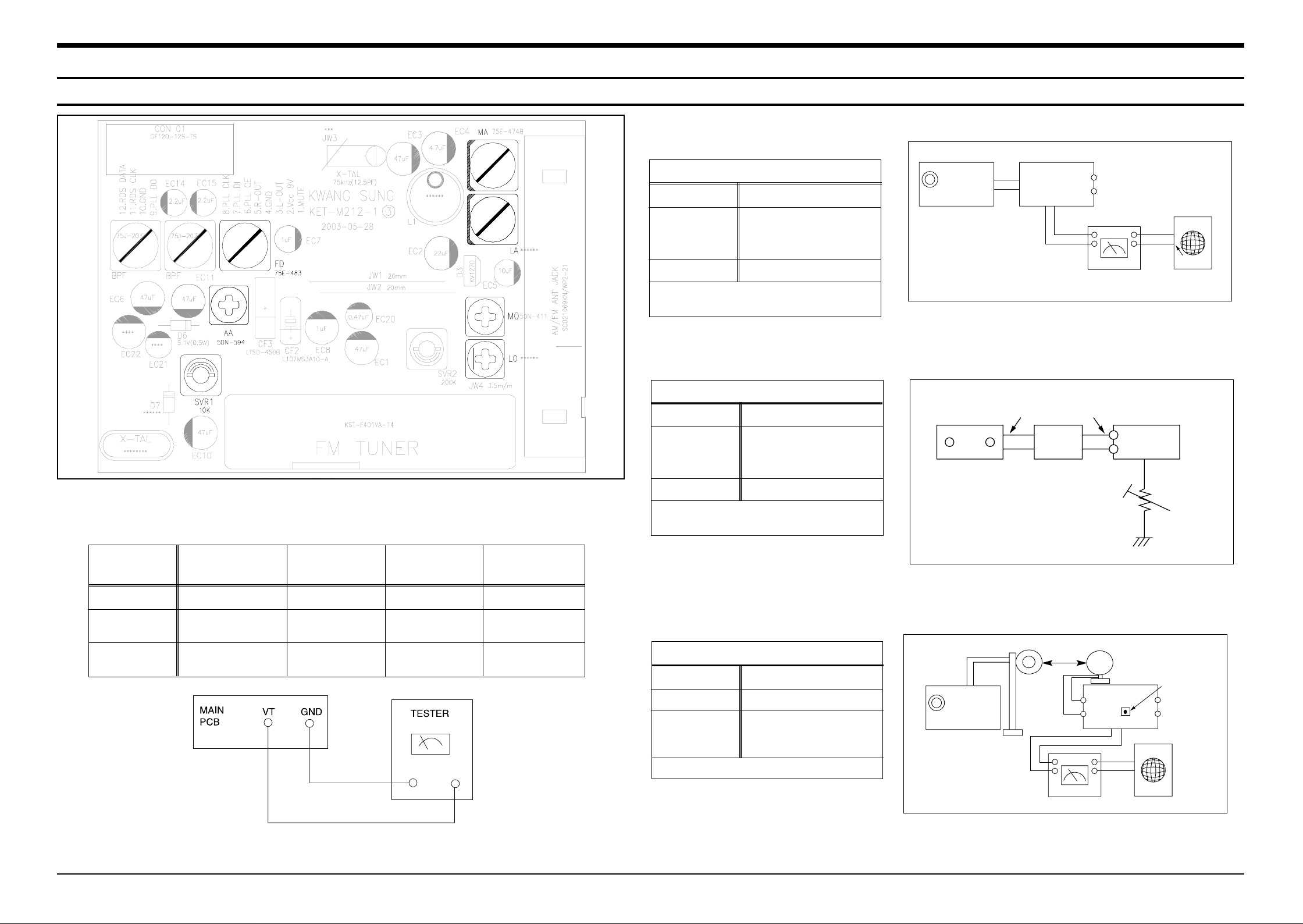
1-1. Tuner
FM THD Adjustment
Output
Output
28 dB(±2dB)
60 dB
Minumum Distortion (0.4% below)
(Figure 1-1)
SSG FREQ.
Adjustment
point
(FM DET)
98 MHz
FD
FM Search Level Adjustment
Adjust SVR1 so that “TUNED” of LCD is
lighted (Figure 1-2)
Figure1-2 FM Auto Search Level Adjustment
*Adjust FM S.S.G level to 28dB
Figure1-1 IF CENTER and THD Adjustment
SSG FREQ.
Adjustment
point
(SVR1)
98 MHz
SVR1 (10KΩ)
FM S.S.G
GND
28 dB
FM S.S.G
Output
GND
Speaker
Terminal
FM
Antenna
Terminal
Distortion Meter
Input
SET
Input
output
Oscilloscope
FM IN
FM Antenna
SET
10 kΩ
AM SSG
450KHZ
INPUT
AM ANT
IN
Speaker Terminal
60cm
AM IF
VTVM Oscilloscope
AM(MW) I.F Adjustment
Maximum output (Figure 1-3)
SSG FREQ.
Frequency
Adjustment
point
450 kHz
522 kHz
AA
Figure1-3 AM I.F Adjustment
OUTPUT
* Adjustment Location of Tuner PCB
Fig 1-4 OSC Voltage
AM(MW) OSC
Adjustment
Output
1~7.0±0.5V
Received FREQ.
Adjustment
point
522~1611 KHz
MO
AM(MW) RF
Adjustment
ITEAM
594 KHz
MA
Maximum
Output(Fig1-4)
LW OSC
Adjustment
146~290 KHz
LO
2~7.0±0.5V
LW RF
Adjustment
150 KHz
LA
Maximum
Output(Fig1-4)
Page 3
Alignment and Adjustments
1-2 Samsung Electronics
Alignment and Adjustments
1-21-2
(GND)
VTVM
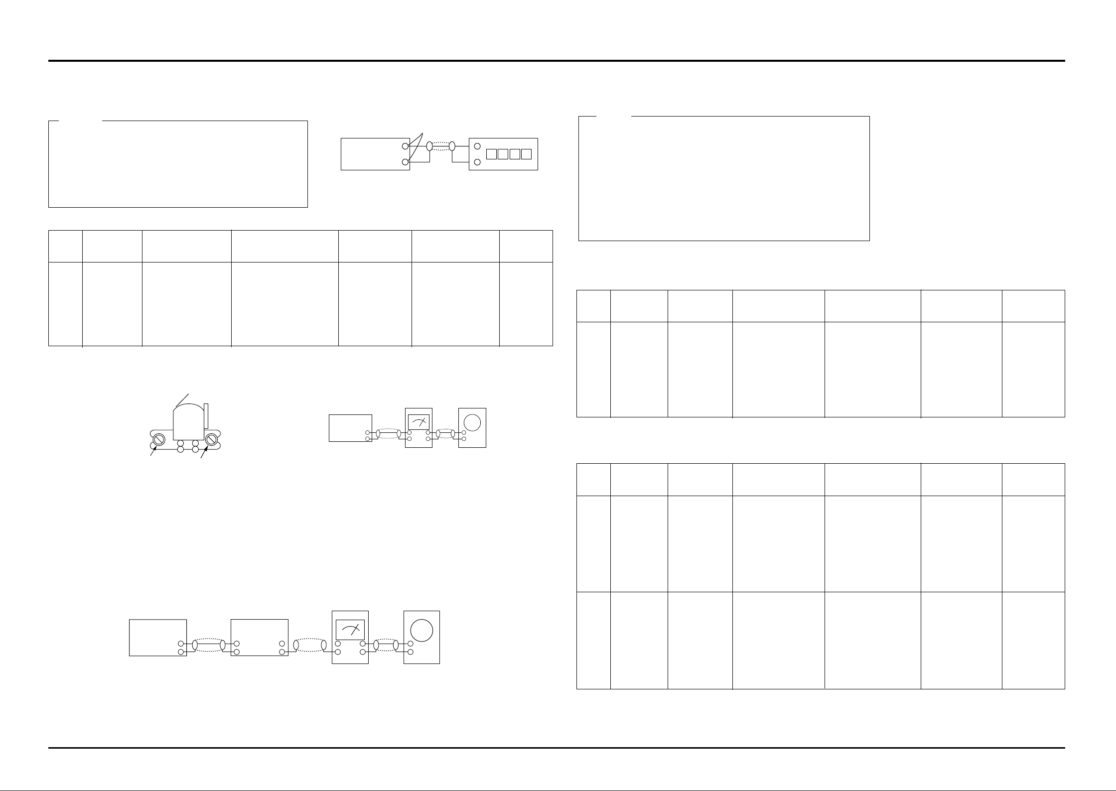
2-1. To Adjust Tape Speed
1) Measuring tape: i) MTT-111 (or equivalent)
(Tapes recorded with 3kHz)
ii) MTT-5512 (or equivalent)
2) Connect the SPK OUT of the MAIN PCB to the fre-
quency counter as in figure 1-5.
1) Before the actual adjustment, clean the play/recording
head.
2) Measuring tape :
i) MTT-114N(or equivalent 10kHz AZIMUTH control)
ii) MTT-5512
3) The cassette deck is connections as shown in figure 1-7.
Notes
Notes
NOR
SPEED
Control
1
SPK OUT
(connected
to the frequency
counter)
Fixed
3KHz
Remark
Standard
To Adjust
Pre-Setup
Item
Step
Pre-Setup
Condition
1) Deck :MTT-111
2) Press PLAY
SW button
AZIMUTH
1
SPK OUT
(VTVM is
connected to
the scope)
- Turn the control
screw to as shown
in Figure 1-6.
Max output
and same phase
(both channels)
After
adjustment
secure it with
REGION
LOCK.
Remark
Standard
To Adjust
Pre-Setup
Item
Step
Pre-Setup
Condition
After putting MTT1 14N into Deck 1
- Press FWD PLA Y
button.
1
2
- Turn the control
screw to as shown in
Figure 1-6.
MAX OUTPUT
and same phase
(both channels)
CHECK TO
7mV(±0.5mV)
Remark
Standard
To Adjust
Pre-Setup
Item
Step
Pre-Setup
Condition
After putting MTT5512 into Deck 2
1) Press REC PLAY button.
2) TAPE PCB JCW3 ,connected
to VTVM
Recording
Bias
Voltage
2-2. To Adjust PlayBack Level/REC
2. Adjust Deck 2 Play Level/ REC BIAS
1. Adjust Deck 1 Play Level
SPK OUT
Figure 1-7
In Out
MAIN PCB
Oscilloscope
2. Cassette Deck
±1%
range
Figure 1-8
Audio OSC.
SET
(MAIN PCB)
Oscilloscope
AUX IN
VTVM
IN
SPK OUT
IN OUT
TP
AZIMUTH
Figure 1-6
Recording /Play head
AZIMUTH control screw
(RVS Play)
AZIMUTH control screw
(FWD Play)
SPK OUT
(VTVM is connected to the
scope)
Fig 1-8
- Turn JSR2L,JSR2R
to the right and left
After adjustment secure
it with
REGION
LOCK.
After putting MTT1 14N into Deck 2
- Press FWD PLA Y
button.
MAIN PCB
output
SPK OUT
Frequency Counter
Figure 1-5
Page 4
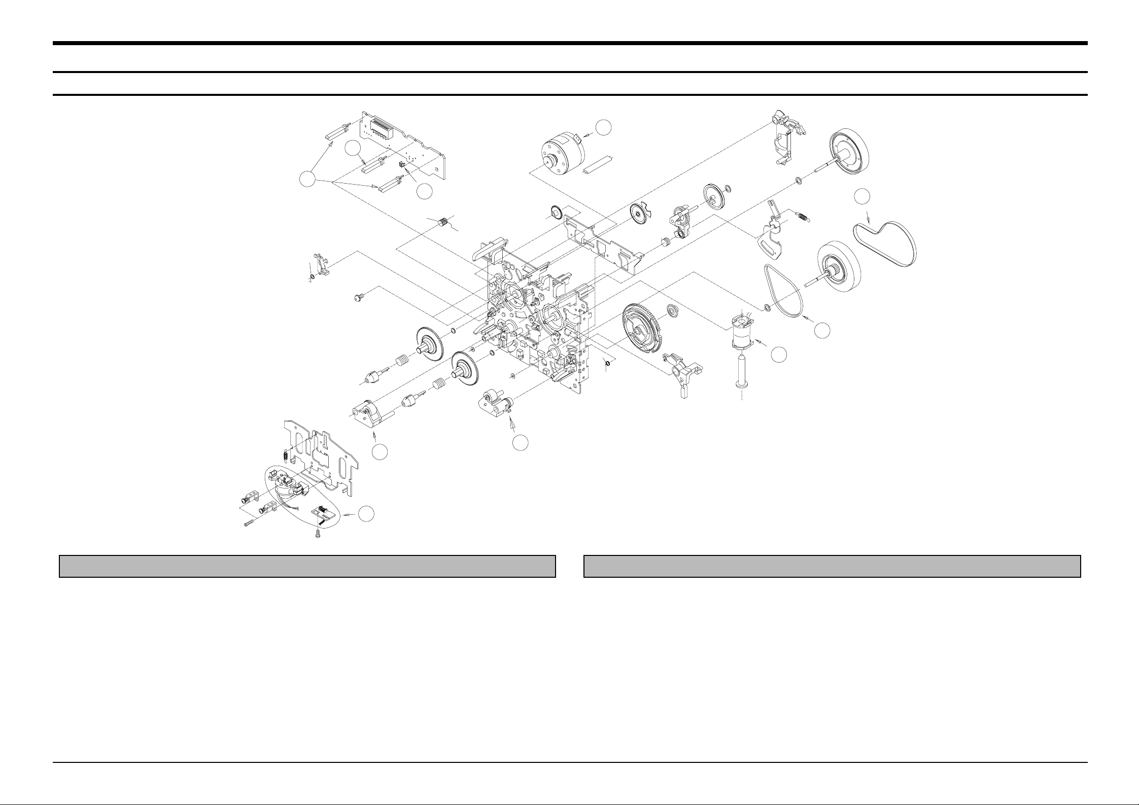
2.Exploded Views and Parts List
2-1 Cassette Deck (OPTION)
Samsung Electronics 2-1
2
4
5
7
8
10
9
6
1
3
No. Code No. Description Specification Remarks
AH59-01272A DECK -CASSETTE CMAL1Z230A A/STOP
1 AH81-01386A R/P HEAD ASS’Y HADKH5655A F513-853
2 AH81-01385A MAIN BELT MAIN BELT
3 AH81-00543C F/R BELT FF19S-31 FF19S-31
4 AH81-00543D SOLENOID F765-292 F765-292
5 AH81-00543E ROLLER PINCH BLK R F514-129 F514-129
7 AH81-01356A MOTOR CCM09-120L2-6
8 AH81-00543H REEL SENSOR SG-107F3;KODENSHI
9 AH81-00543J LEAF S/W - WHITE SPLFF
10 AH81-00543K LEAF S/W - BLK SPLFE1
No. Code No. Description Specification Remarks
AH59-01267A DECK -CASSETTE CMAL1Z230A A/REV.
1 AH81-00543A R/P HEAD ASS’Y HADKH5655A F513-853
2 AH81-00733A MAIN BELT MAIN BELT
3 AH81-00543C F/R BELT FF19S-31 FF19S-31
4 AH81-00543D SOLENOID F765-292 F765-292
5 AH81-00543E ROLLER PINCH BLK R F514-129 F514-129
6 AH81-00543F ROLLER PINCH BLK L F514-130 F514-130
7 AH81-01356A MOTOR CCM09-120L2-6
8 AH81-00543H REEL SENSOR SG-107F3;KODENSHI
9 AH81-00543J LEAF S/W - WHITE SPLFF
10 AH81-00543K LEAF S/W - BLK SPLFE1
Page 5
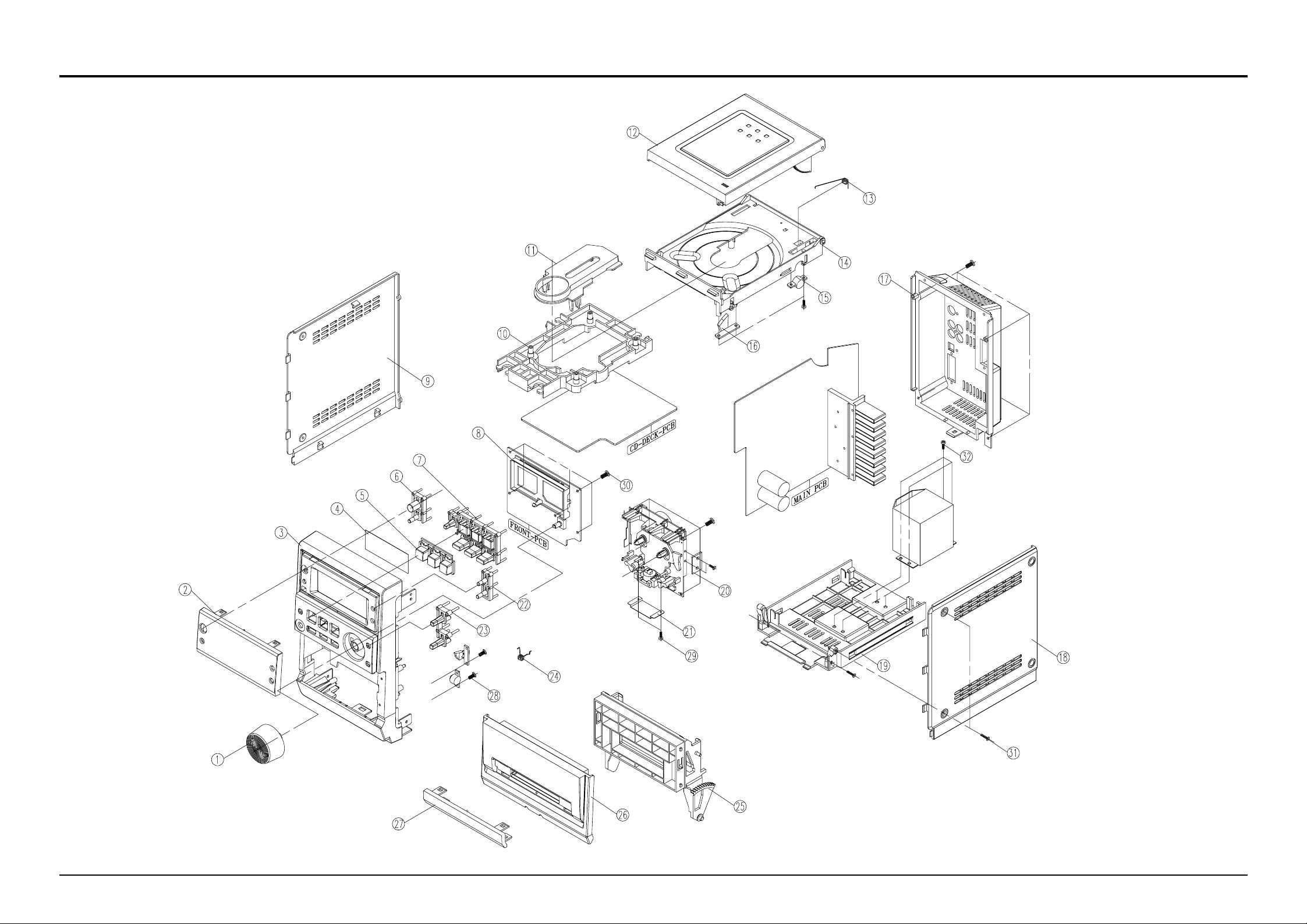
2-2 Total Exploded View and Parts List
Samsung Electronics
2-2
Page 6
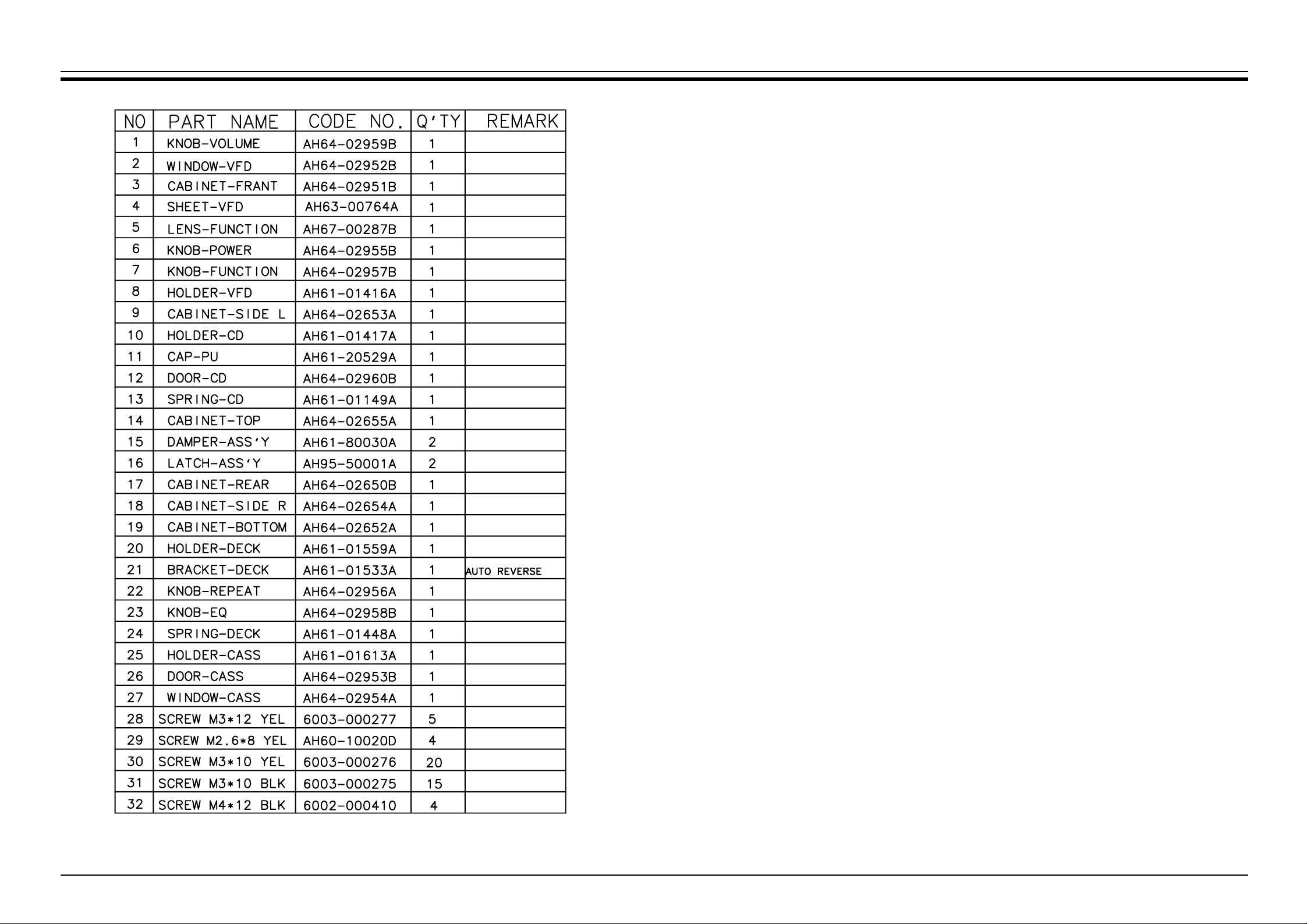
* Parts List of The Exploded View
Samsung Electronics
2-3
Page 7

2-3 SPEAKER Exploded View and Parts list
* CAUTION : It is used the bonding, connect FRONT P ANEL to CABINET WOODEN.
So when the disassembly, take extreme care not to damage the SPEAKER.
Samsung Electronics
2-4
Page 8

AH26-00292A TRANS POWER;-,MM-J4,-,-,115/230V,-,-,-,6
AH39-00320B CBF COAXIAL CABLE;MAX-L68,110REC,-,1007#
AH39-50030D WIRE HARNESS;RING/REC,200mm,1007#24,BLK
AH42-20001P ANT LOOP;-,KS971120-01,18.5UH##10%,AH59-01159F REMOCON;MM-J4,SAMSUNG,-,-,28KEY,-,-,-,
AH39-00257E POWER CORD;KOR,-,CP2,250V,3A,1830MM/300M KOREA
AH39-00257A POWER CORD;KOR,-,CP2,250V,3A,1830MM/300M EXP
AH40-00050B TUNER-PACK ASSY;KST-MJ111MS0-60,FM/MW,-, KOREA
AH40-00043A TUNER-PACK ASSY;FM/MW/L W ,RDS,FM87.5~108.0MHz EUROPE(RDS)
AH40-00042A TUNER-PACK ASSY;FM/MW/L W ,RDS,FM64~108.0MHz CIS(RDS)
AH40-00044A TUNER-PACK ASSY;FM/MW,MW520~1720KHz ASIA(T-BAND)
AH40-00045A TUNER-PACK ASSY;FM/MW/L W ,FM64~108.0MHz CIS(NO RDS)
AH40-00046A TUNER-PACK ASSY;FM/MW/L W ,FM87.5~108.0MHz LW BAND
AH40-00049A TUNER-PACK ASSY;FM/MW/SW1/SW2 SW BAND
AH59-01083D DECK-CD PACK MECHA ASS’Y;-,MM-J6,-,-,-,
3409-001078 SWITCH-LEAF;16Vdc,500mA,10gf,SPST
3809-001554 CABLE-FLAT;30V,80C,85MM,16P,1MM,UL20696
6003-001210 SCREW-TAPTITE;PWH,+,B,M2.6,L6.0,ZPC(BLK)
AH61-01417A CASE-TOP;MCD-CM600,PC CLEAR,-,-,-,-,PAC
AH61-20529A CAP-PICK UP;RCD380,ABS,-,-,-,BLK,AH61-22002A HOLDER-PCB;DVC-650S,NYLON 66,-,-,-,-,OD3
AH62-30047A HEAT SINK;ETHD,-,T0.5,-,-,-,MAX-555,AH73-00010A RUBBER—HOLDER;BUTYLENE,-,S-2000,AH73-00025B RUBBER-CD;CMS-D100,BUTYL 15,-,-,-,-,-,-,
AH59-01082A DECK-CDP;CMS-P31BG6,MM-B7,BALL,-,-,S0HAH30-00037A PICK UP;SOH-AAU(1H20L),-,-,-,100*80*45
AH92-01561C ASSY PCB-CD(ONLY);MM-J6,G3HI-1CD/CDP,3.5
R502L 2001-000281 R-CARBON;100OHM,5%,1/8W,AA,TP,1.8X3.2MM
C302 2401-001895 C-AL;100uF,20%,16V,GP,TP,6.3x11,2.5
C215 2401-001934 C-AL;220uF,20%,6.3V,GP,-,6.3x7,X201 2802-000211 RESONATOR-CERAMIC;16.93MHz,0.5%,TP,10.0x
CW105 3708-000189 CONNECTOR-FPC/FFC/PIC;17P,1.25MM,ANGLE,S
CW101 3708-001388 CONNECTOR-FPC/FFC/PIC;16P,1MM,ANGLE,SN,N
CW103 3711-000826 CONNECTOR-HEADER;BOX,2P,1R,2mm,ANGLE,SN
CW102 3711-000906 CONNECTOR-HEADER;BOX,3P,1R,2mm,ANGLE,SN
CW106 3711-001136 CONNECTOR-HEADER;BOX,8P,1R,2mm,ANGLE,SN
GND1 AH39-00293A CONNECT WIRE;RCA300,1007#26,-,1P,200MM,W
ZD301 0403-000344 DIODE-ZENER;UZ3.9B,3.7-4.1V,500MW,DO-35,
Q302 0501-000010 TR-SMALL SIGNAL;KSC1008,NPN,800mW,TO-92,
Q101 0501-000314 TR-SMALL SIGNAL;KSA812,PNP,150mW,SOT-23,
Q301 0501-000610 TR-SMALL SIGNAL;KSA928A-Y,PNP,1W,TO-92L,
IC201 0904-001524 IC-DSP;5L9290,-,QFP,48P,472MIL,16.934
IC301 1003-000179 IC-MOTOR DRIVER;KA9258D,SOP,28P,-,SINGLE
IC101 1204-001799 IC-ASP;KB9226,LQFP,48P,393MIL,PLASTIC
R805 2001-000429 R-CARBON;1KOHM,5%,1/8W,AA,TP,1.8X3.2MM
R804 2001-000429 R-CARBON;1KOHM,5%,1/8W,AA,TP,1.8X3.2MM
R213 2001-000429 R-CARBON;1KOHM,5%,1/8W,AA,TP,1.8X3.2MM
R205 2001-000429 R-CARBON;1KOHM,5%,1/8W,AA,TP,1.8X3.2MM
R211 2001-000429 R-CARBON;1KOHM,5%,1/8W,AA,TP,1.8X3.2MM
R212 2001-000429 R-CARBON;1KOHM,5%,1/8W,AA,TP,1.8X3.2MM
R206 2001-000515 R-CARBON;220OHM,5%,1/8W,AA,TP,1.8X3.2MM
R803 2001-000515 R-CARBON;220OHM,5%,1/8W,AA,TP,1.8X3.2MM
R806 2001-000515 R-CARBON;220OHM,5%,1/8W,AA,TP,1.8X3.2MM
R302 2001-001006 R-CARBON;82OHM,5%,1/8W,AA,TP,1.8X3.2MM
R114 2007-000001 R-CHIP;68Kohm,5%,1/8W,TP,2012
J43 2007-000029 R-CHIP;0ohm,5%,1/8W,TP,2012
J44 2007-000029 R-CHIP;0ohm,5%,1/8W,TP,2012
J46 2007-000029 R-CHIP;0ohm,5%,1/8W,TP,2012
JW11 2007-000029 R-CHIP;0ohm,5%,1/8W,TP,2012
JW24 2007-000029 R-CHIP;0ohm,5%,1/8W,TP,2012
J42 2007-000029 R-CHIP;0ohm,5%,1/8W,TP,2012
J18 2007-000029 R-CHIP;0ohm,5%,1/8W,TP,2012
J20 2007-000029 R-CHIP;0ohm,5%,1/8W,TP,2012
J35 2007-000029 R-CHIP;0ohm,5%,1/8W,TP,2012
J36 2007-000029 R-CHIP;0ohm,5%,1/8W,TP,2012
J41 2007-000029 R-CHIP;0ohm,5%,1/8W,TP,2012
J3 2007-000033 R-CHIP;0ohm,5%,1/4W,TP,3216
J25 2007-000033 R-CHIP;0ohm,5%,1/4W,TP,3216
J24 2007-000033 R-CHIP;0ohm,5%,1/4W,TP,3216
J23 2007-000033 R-CHIP;0ohm,5%,1/4W,TP,3216
J22 2007-000033 R-CHIP;0ohm,5%,1/4W,TP,3216
J4 2007-000033 R-CHIP;0ohm,5%,1/4W,TP,3216
J9 2007-000033 R-CHIP;0ohm,5%,1/4W,TP,3216
J8 2007-000033 R-CHIP;0ohm,5%,1/4W,TP,3216
J7 2007-000033 R-CHIP;0ohm,5%,1/4W,TP,3216
J6 2007-000033 R-CHIP;0ohm,5%,1/4W,TP,3216
J5 2007-000033 R-CHIP;0ohm,5%,1/4W,TP,3216
J15 2007-000033 R-CHIP;0ohm,5%,1/4W,TP,3216
J13 2007-000033 R-CHIP;0ohm,5%,1/4W,TP,3216
J12 2007-000033 R-CHIP;0ohm,5%,1/4W,TP,3216
J10 2007-000033 R-CHIP;0ohm,5%,1/4W,TP,3216
J1 2007-000033 R-CHIP;0ohm,5%,1/4W,TP,3216
J16 2007-000033 R-CHIP;0ohm,5%,1/4W,TP,3216
J20 2007-000033 R-CHIP;0ohm,5%,1/4W,TP,3216
J2 2007-000033 R-CHIP;0ohm,5%,1/4W,TP,3216
J19 2007-000033 R-CHIP;0ohm,5%,1/4W,TP,3216
J18 2007-000033 R-CHIP;0ohm,5%,1/4W,TP,3216
J17 2007-000033 R-CHIP;0ohm,5%,1/4W,TP,3216
R501L 2007-000282 R-CHIP;100Kohm,5%,1/8W,TP,2012
R501R 2007-000282 R-CHIP;100Kohm,5%,1/8W,TP,2012
R502R 2007-000290 R-CHIP;100ohm,5%,1/8W,TP,2012
R132 2007-000300 R-CHIP;10Kohm,5%,1/8W,TP,2012
R133 2007-000300 R-CHIP;10Kohm,5%,1/8W,TP,2012
R108 2007-000308 R-CHIP;10ohm,5%,1/8W,TP,2012
R124 2007-000338 R-CHIP;120Kohm,5%,1/8W,TP,2012
R125 2007-000338 R-CHIP;120Kohm,5%,1/8W,TP,2012
R117 2007-000355 R-CHIP;12Kohm,5%,1/8W,TP,2012
R121 2007-000409 R-CHIP;15Kohm,5%,1/8W,TP,2012
R113 2007-000444 R-CHIP;180Kohm,5%,1/8W,TP,2012
R110 2007-000457 R-CHIP;18Kohm,5%,1/8W,TP,2012
R209 2007-000468 R-CHIP;1Kohm,5%,1/8W,TP,2012
R118 2007-000477 R-CHIP;1Mohm,5%,1/8W,TP,2012
R202 2007-000477 R-CHIP;1Mohm,5%,1/8W,TP,2012
R303 2007-000502 R-CHIP;2.2ohm,5%,1/8W,TP,2012
R116 2007-000546 R-CHIP;20Kohm,5%,1/8W,TP,2012
R210 2007-000572 R-CHIP;220ohm,5%,1/8W,TP,2012
R208 2007-000572 R-CHIP;220ohm,5%,1/8W,TP,2012
R207 2007-000572 R-CHIP;220ohm,5%,1/8W,TP,2012
R204 2007-000572 R-CHIP;220ohm,5%,1/8W,TP,2012
R128 2007-000653 R-CHIP;27Kohm,5%,1/8W,TP,2012
DR2 2007-000872 R-CHIP;4.7Kohm,5%,1/8W,TP,2012
DR1 2007-000872 R-CHIP;4.7Kohm,5%,1/8W,TP,2012
R129 2007-000941 R-CHIP;47Kohm,5%,1/8W,TP,2012
R123 2007-000941 R-CHIP;47Kohm,5%,1/8W,TP,2012
R101 2007-001039 R-CHIP;56Kohm,5%,1/8W,TP,2012
R102 2007-001039 R-CHIP;56Kohm,5%,1/8W,TP,2012
R103 2007-001039 R-CHIP;56Kohm,5%,1/8W,TP,2012
R104 2007-001039 R-CHIP;56Kohm,5%,1/8W,TP,2012
R120 2007-001039 R-CHIP;56Kohm,5%,1/8W,TP,2012
R126 2007-001039 R-CHIP;56Kohm,5%,1/8W,TP,2012
R115 2007-001177 R-CHIP;8.2Kohm,5%,1/8W,TP,2012
R112 2007-001195 R-CHIP;820Kohm,5%,1/8W,TP,2012
R105 2007-001208 R-CHIP;82Kohm,5%,1/8W,TP,2012
R106 2007-001208 R-CHIP;82Kohm,5%,1/8W,TP,2012
R119 2007-001208 R-CHIP;82Kohm,5%,1/8W,TP,2012
R127 2007-001208 R-CHIP;82Kohm,5%,1/8W,TP,2012
R107 2007-001216 R-CHIP;82ohm,5%,1/8W,TP,2012
R301 2008-000140 R-FUSIBLE;2.2ohm,5%,1/2W,AA,TP,3.5x9.4mm
C205 2203-000203 C-CER,CHIP;100nF,10%,16V,X7R,TP,2012,2mm
C211 2203-000203 C-CER,CHIP;100nF,10%,16V,X7R,TP,2012,2mm
C213 2203-000203 C-CER,CHIP;100nF,10%,16V,X7R,TP,2012,2mm
C216 2203-000203 C-CER,CHIP;100nF,10%,16V,X7R,TP,2012,2mm
C218 2203-000203 C-CER,CHIP;100nF,10%,16V,X7R,TP,2012,2mm
C220 2203-000203 C-CER,CHIP;100nF,10%,16V,X7R,TP,2012,2mm
C402 2203-000203 C-CER,CHIP;100nF,10%,16V,X7R,TP,2012,2mm
C204 2203-000203 C-CER,CHIP;100nF,10%,16V,X7R,TP,2012,2mm
C115 2203-000203 C-CER,CHIP;100nF,10%,16V,X7R,TP,2012,2mm
C116 2203-000203 C-CER,CHIP;100nF,10%,16V,X7R,TP,2012,2mm
C118 2203-000203 C-CER,CHIP;100nF,10%,16V,X7R,TP,2012,2mm
C124 2203-000203 C-CER,CHIP;100nF,10%,16V,X7R,TP,2012,2mm
C129 2203-000203 C-CER,CHIP;100nF,10%,16V,X7R,TP,2012,2mm
C130 2203-000203 C-CER,CHIP;100nF,10%,16V,X7R,TP,2012,2mm
C132 2203-000203 C-CER,CHIP;100nF,10%,16V,X7R,TP,2012,2mm
C103 2203-000260 C-CER,CHIP;10nF,10%,50V,X7R,TP,2012
C121 2203-000260 C-CER,CHIP;10nF,10%,50V,X7R,TP,2012
C134 2203-000260 C-CER,CHIP;10nF,10%,50V,X7R,TP,2012
C207 2203-000260 C-CER,CHIP;10nF,10%,50V,X7R,TP,2012
C401 2203-000260 C-CER,CHIP;10nF,10%,50V,X7R,TP,2012
C124 2203-000347 C-CER,CHIP;150NF,10%,50V,C0G,TP,2012
JW9<->JW1 2203-000477 C-CER,CHIP;1000NF,+80-20%,16V,Y5V,TP,201
C126 2203-000495 C-CER,CHIP;2.2nF,10%,50V,X7R,TP,2012
C127 2203-000595 C-CER,CHIP;0.22NF,5%,50V,C0G,TP,2012
EC1 2203-000595 C-CER,CHIP;0.22NF,5%,50V,C0G,TP,2012
C105 2203-000609 C-CER,CHIP;22nF,10%,50V,X7R,TP,2012
C128 2203-000802 C-CER,CHIP;33nF,10%,50V,X7R,TP,2012
C119 2203-000802 C-CER,CHIP;33nF,10%,50V,X7R,TP,2012
C125 2203-000840 C-CER,CHIP;0.39NF,5%,50V,C0G,TP,2012
C208 2203-000858 C-CER,CHIP;0.039NF,5%,50V,C0G,TP,2012
C111 2203-000892 C-CER,CHIP;4.7nF,10%,50V,X7R,TP,2012
C112 2203-000892 C-CER,CHIP;4.7nF,10%,50V,X7R,TP,2012
C135 2203-000919 C-CER,CHIP;470nF,+80-20%,16V,Y5V,TP,2012
C120 2203-000919 C-CER,CHIP;470nF,+80-20%,16V,Y5V,TP,2012
C109 2203-001026 C-CER,CHIP;0.004nF,0.25pF,50V,SL,TP,2012
C124A 2203-001063 C-CER,CHIP;56nF,10%,16V,X7R,TP,1608,C106 2203-001137 C-CER,CHIP;68nF,+80-20%,50V,Y5V,TP,2012,
C122 2203-001137 C-CER,CHIP;68nF,+80-20%,50V,Y5V,TP,2012,
C203 2203-001223 C-CER,CHIP;0.82nF,10%,50V,X7R,TP,2012
C502R 2203-001537 C-CER,CHIP;1nF,10%,50V,X7R,TP,2012
C502L 2203-001537 C-CER,CHIP;1nF,10%,50V,X7R,TP,2012
C117 2203-001537 C-CER,CHIP;1nF,10%,50V,X7R,TP,2012
C102 2203-001537 C-CER,CHIP;1nF,10%,50V,X7R,TP,2012
C104 2203-001551 C-CER,CHIP;1.5nF,10%,50V,X7R,TP,2012
C202 2203-001619 C-CER,CHIP;0.027nF,5%,50V,NP0,TP,2012
Location no. Code no. Description & Specification Remarks
Location no. Code no. Description & Specification Remarks
Samsung Electronics 3-1
3. Electrical Parts List
*S.N.A. : Service Not Available
Page 9

C201 2203-001619 C-CER,CHIP;0.027nF,5%,50V,NP0,TP,2012
C123 2401-000407 C-AL;10UF,20%,16V,GP,TP,3.5X5,2.5
C303 2401-001102 C-AL;330uF,20%,16V,GP,TP,8x11.5mm,5
C301 2401-001102 C-AL;330uF,20%,16V,GP,TP,8x11.5mm,5
C501R 2401-001238 C-AL;4.7uF,20%,25V,GP,BK,3x5,1mm
C501L 2401-001238 C-AL;4.7uF,20%,25V,GP,BK,3x5,1mm
C114 2401-001238 C-AL;4.7uF,20%,25V,GP,BK,3x5,1mm
C212 2401-001502 C-AL;47uF,20%,16V,GP,TP,6.3x5,2.5
C133 2401-001502 C-AL;47uF,20%,16V,GP,TP,6.3x5,2.5
C210 2401-001934 C-AL;220uF,20%,6.3V,GP,-,6.3x7,C215 2401-001934 C-AL;220uF,20%,6.3V,GP,-,6.3x7,C217 2401-001934 C-AL;220uF,20%,6.3V,GP,-,6.3x7,C304 2401-001934 C-AL;220uF,20%,6.3V,GP,-,6.3x7,C101 2401-001934 C-AL;220uF,20%,6.3V,GP,-,6.3x7,C107 2401-001934 C-AL;220uF,20%,6.3V,GP,-,6.3x7,C108 2401-001934 C-AL;220uF,20%,6.3V,GP,-,6.3x7,C131 2401-001934 C-AL;220uF,20%,6.3V,GP,-,6.3x7,DL1 2701-000114 INDUCTOR-AXIAL;10UH,10%,2534
PCB AH41-00392C PCB;G3HI-1CD,PENOL, 2LAYER,1 LAYER
AH92-01987E ASSY PCB-FRONT;MM-J4,-
RD4 0402-000157 DIODE-RECTIFIER;1N5402,200V,3A,DO-201AD,
RD3 0402-000157 DIODE-RECTIFIER;1N5402,200V,3A,DO-201AD,
RD2 0402-000157 DIODE-RECTIFIER;1N5402,200V,3A,DO-201AD,
RD1 0402-000157 DIODE-RECTIFIER;1N5402,200V,3A,DO-201AD,
PC2 2201-002128 C-CERAMIC,DISC;4.7NF,20%,400V,Y5U,BK,15X
PC1 2201-002128 C-CERAMIC,DISC;4.7NF,20%,400V,Y5U,BK,15X
UX2 2801-001394 CRYSTAL-UNIT;32.768KHz,20ppm,28-AAY,12.5
UX1 2802-001174 RESONATOR-CERAMIC;10MHZ,0.5%,BK,8X3.5X3M
SW1 3405-000101 SWITCH-MICRO;1.6V,1A,70gf,SPST
UVR1 3406-001050 SWITCH-ROTARY;5V DC,0.5mA,click,12mm
PF3 3601-000170 FUSE-CARTRIDGE;250V,1.6A,TIME-LAG,GLASS,
PF4 3601-000282 FUSE;250V,4A,TIME-LAG,GLASS,5.2x20m
PF2 3601-000318 FUSE-CARTRIDGE;250V,800mA,TIME-LAG,GLASS
UWA6 3708-001488 CONNECTOR-FPC/FFC/PIC;30P,1.25MM,STRAIGH
UWA9 3708-001723 CONNECTOR-FPC/FFC/PIC;17P,1.25MM,STRAIGH
PWA1 3711-000190 CONNECTOR-HEADER;1WALL,2P,1R,7.92MM,STRA
UWA2 3711-001009 CONNECTOR-HEADER;BOX,5P,1R,2.5mm,ANGLE,S
PWA2 3711-003113 CONNECTOR-HEADER;BOX,9P,1R,2.5mm,STRAIGH
HJACK1 3722-000351 JACK-PHONE;11P,3.5PI,AG,BLK,VFD AH07-00113A VF DISPLAY;HNA-09MS17T,MM-J4/J6,100*25,1
PL1 AH27-10001F COIL-CHOKE;27uH,K,Q30,-,-,DR(6.5*7.5),-,
PL2 AH27-10001F COIL-CHOKE;27uH,K,Q30,-,-,DR(6.5*7.5),-,
CN1 AH39-00108A LEAD CONNECTOR ASSY;-,5295,51004,2P,80MM
UEYE1 AH59-60010E MODULE REMOCON;KSM-913TE5,-,-,25CM,G.T:#
CAS AH61-01416A CASE-BOTTOM;MCD-CM600,PC-ABS,-,-,-,-,PAC
TAP1 AH65-30013A CLAMP-CORD;-,-,-,-,-,-
AH81-01327T A/S PART-POWE PCB;MM-J4,POWER PCB ASS’Y,
AH81-01327V A/S PART-FRONT;MM-ZJ6,FRONT PCB ASS’Y,-,
UD130 0401-000101 DIODE-SWITCHING;1N4148,75V,150MA,DO-35,T
UD15 0401-000101 DIODE-SWITCHING;1N4148,75V,150MA,DO-35,T
UD2 0401-000101 DIODE-SWITCHING;1N4148,75V,150MA,DO-35,T
UD4 0401-000101 DIODE-SWITCHING;1N4148,75V,150MA,DO-35,T
UD5 0401-000101 DIODE-SWITCHING;1N4148,75V,150MA,DO-35,T
UD7 0401-000101 DIODE-SWITCHING;1N4148,75V,150MA,DO-35,T
UD120 0401-000101 DIODE-SWITCHING;1N4148,75V,150MA,DO-35,T
UD13 0401-000101 DIODE-SWITCHING;1N4148,75V,150MA,DO-35,T
UD11 0401-000101 DIODE-SWITCHING;1N4148,75V,150MA,DO-35,T
UD12 0401-000101 DIODE-SWITCHING;1N4148,75V,150MA,DO-35,T
UD1 0401-000101 DIODE-SWITCHING;1N4148,75V,150MA,DO-35,T
UD100 0401-000101 DIODE-SWITCHING;1N4148,75V,150MA,DO-35,T
RD18 0402-000127 DIODE-RECTIFIER;1N4002,100V,1A,DO-41,TP
RD5 0402-000127 DIODE-RECTIFIER;1N4002,100V,1A,DO-41,TP
RD6 0402-000127 DIODE-RECTIFIER;1N4002,100V,1A,DO-41,TP
RD7 0402-000127 DIODE-RECTIFIER;1N4002,100V,1A,DO-41,TP
RD8 0402-000127 DIODE-RECTIFIER;1N4002,100V,1A,DO-41,TP
RD9 0402-000127 DIODE-RECTIFIER;1N4002,100V,1A,DO-41,TP
UQ1 0501-000398 TR-SMALL SIGNAL;KSC945,NPN,250mW,TO-92,T
UR53 2001-000241 R-CARBON;1.5KOHM,5%,1/8W,AA,TP,1.8X3.2M
UR60 2001-000241 R-CARBON;1.5KOHM,5%,1/8W,AA,TP,1.8X3.2M
UR61 2001-000258 R-CARBON;1.8KOHM,5%,1/8W,AA,TP,1.8X3.2M
UR54 2001-000258 R-CARBON;1.8KOHM,5%,1/8W,AA,TP,1.8X3.2M
UR45 2001-000281 R-CARBON;100OHM,5%,1/8W,AA,TP,1.8X3.2MM
UR48 2001-000281 R-CARBON;100OHM,5%,1/8W,AA,TP,1.8X3.2MM
UR50 2001-000281 R-CARBON;100OHM,5%,1/8W,AA,TP,1.8X3.2MM
UR51 2001-000281 R-CARBON;100OHM,5%,1/8W,AA,TP,1.8X3.2MM
UR58 2001-000281 R-CARBON;100OHM,5%,1/8W,AA,TP,1.8X3.2MM
UR38 2001-000281 R-CARBON;100OHM,5%,1/8W,AA,TP,1.8X3.2MM
UR41 2001-000281 R-CARBON;100OHM,5%,1/8W,AA,TP,1.8X3.2MM
UR42 2001-000281 R-CARBON;100OHM,5%,1/8W,AA,TP,1.8X3.2MM
UR43 2001-000281 R-CARBON;100OHM,5%,1/8W,AA,TP,1.8X3.2MM
UR44 2001-000281 R-CARBON;100OHM,5%,1/8W,AA,TP,1.8X3.2MM
UR206 2001-000290 R-CARBON;10KOHM,5%,1/8W,AA,TP,1.8X3.2MM
UR112 2001-000429 R-CARBON;1KOHM,5%,1/8W,AA,TP,1.8X3.2MM
UR23 2001-000429 R-CARBON;1KOHM,5%,1/8W,AA,TP,1.8X3.2MM
UR24 2001-000429 R-CARBON;1KOHM,5%,1/8W,AA,TP,1.8X3.2MM
UR68 2001-000429 R-CARBON;1KOHM,5%,1/8W,AA,TP,1.8X3.2MM
UR10 2001-000429 R-CARBON;1KOHM,5%,1/8W,AA,TP,1.8X3.2MM
UR100 2001-000429 R-CARBON;1KOHM,5%,1/8W,AA,TP,1.8X3.2MM
UR101 2001-000429 R-CARBON;1KOHM,5%,1/8W,AA,TP,1.8X3.2MM
UR111 2001-000429 R-CARBON;1KOHM,5%,1/8W,AA,TP,1.8X3.2MM
UR64 2001-000449 R-CARBON;2.2KOHM,5%,1/8W,AA,TP,1.8X3.2M
UR55 2001-000449 R-CARBON;2.2KOHM,5%,1/8W,AA,TP,1.8X3.2M
UR56 2001-000591 R-CARBON;3.3KOHM,5%,1/8W,AA,TP,1.8X3.2M
UR63 2001-000591 R-CARBON;3.3KOHM,5%,1/8W,AA,TP,1.8X3.2M
JW25 2007-000029 R-CHIP;0ohm,5%,1/8W,TP,2012
JW7 2007-000029 R-CHIP;0ohm,5%,1/8W,TP,2012
UR48 2007-000029 R-CHIP;0ohm,5%,1/8W,TP,2012
JW23 2007-000033 R-CHIP;0ohm,5%,1/4W,TP,3216
UR73 2007-000282 R-CHIP;100Kohm,5%,1/8W,TP,2012
UR74 2007-000282 R-CHIP;100Kohm,5%,1/8W,TP,2012
UR75 2007-000282 R-CHIP;100Kohm,5%,1/8W,TP,2012
UR76 2007-000282 R-CHIP;100Kohm,5%,1/8W,TP,2012
UR77 2007-000282 R-CHIP;100Kohm,5%,1/8W,TP,2012
UR78 2007-000282 R-CHIP;100Kohm,5%,1/8W,TP,2012
UR79 2007-000282 R-CHIP;100Kohm,5%,1/8W,TP,2012
UR80 2007-000282 R-CHIP;100Kohm,5%,1/8W,TP,2012
UR72 2007-000282 R-CHIP;100Kohm,5%,1/8W,TP,2012
UR200 2007-000282 R-CHIP;100Kohm,5%,1/8W,TP,2012
UR119 2007-000282 R-CHIP;100Kohm,5%,1/8W,TP,2012
UR118 2007-000282 R-CHIP;100Kohm,5%,1/8W,TP,2012
UR201 2007-000282 R-CHIP;100Kohm,5%,1/8W,TP,2012
UR202 2007-000282 R-CHIP;100Kohm,5%,1/8W,TP,2012
UR203 2007-000282 R-CHIP;100Kohm,5%,1/8W,TP,2012
UR204 2007-000282 R-CHIP;100Kohm,5%,1/8W,TP,2012
UR71 2007-000282 R-CHIP;100Kohm,5%,1/8W,TP,2012
UR81 2007-000282 R-CHIP;100Kohm,5%,1/8W,TP,2012
UR88 2007-000282 R-CHIP;100Kohm,5%,1/8W,TP,2012
UR89 2007-000282 R-CHIP;100Kohm,5%,1/8W,TP,2012
UR90 2007-000282 R-CHIP;100Kohm,5%,1/8W,TP,2012
UR91 2007-000282 R-CHIP;100Kohm,5%,1/8W,TP,2012
UR92 2007-000282 R-CHIP;100Kohm,5%,1/8W,TP,2012
UR93 2007-000282 R-CHIP;100Kohm,5%,1/8W,TP,2012
UR82 2007-000282 R-CHIP;100Kohm,5%,1/8W,TP,2012
UR83 2007-000282 R-CHIP;100Kohm,5%,1/8W,TP,2012
UR84 2007-000282 R-CHIP;100Kohm,5%,1/8W,TP,2012
UR87 2007-000282 R-CHIP;100Kohm,5%,1/8W,TP,2012
UR86 2007-000282 R-CHIP;100Kohm,5%,1/8W,TP,2012
UR85 2007-000282 R-CHIP;100Kohm,5%,1/8W,TP,2012
UR94 2007-000300 R-CHIP;10Kohm,5%,1/8W,TP,2012
UR62 2007-000300 R-CHIP;10Kohm,5%,1/8W,TP,2012
UR17 2007-000300 R-CHIP;10Kohm,5%,1/8W,TP,2012
UR15 2007-000300 R-CHIP;10Kohm,5%,1/8W,TP,2012
UR14 2007-000300 R-CHIP;10Kohm,5%,1/8W,TP,2012
UR16 2007-000401 R-CHIP;150ohm,5%,1/8W,TP,2012
UR52 2007-000468 R-CHIP;1Kohm,5%,1/8W,TP,2012
UR2 2007-000468 R-CHIP;1Kohm,5%,1/8W,TP,2012
UR115 2007-000468 R-CHIP;1Kohm,5%,1/8W,TP,2012
UR113 2007-000468 R-CHIP;1Kohm,5%,1/8W,TP,2012
UR102 2007-000468 R-CHIP;1Kohm,5%,1/8W,TP,2012
UR1 2007-000468 R-CHIP;1Kohm,5%,1/8W,TP,2012
UR59 2007-000468 R-CHIP;1Kohm,5%,1/8W,TP,2012
UR4 2007-000477 R-CHIP;1Mohm,5%,1/8W,TP,2012
UR18 2007-000493 R-CHIP;2.2Kohm,5%,1/8W,TP,2012
UR103 2007-000565 R-CHIP;220Kohm,5%,1/8W,TP,2012
AR8R 2007-000644 R-CHIP;270OHM,5%,1/2W,DA,TP,5025
AR8L 2007-000644 R-CHIP;270OHM,5%,1/2W,DA,TP,5025
UR57 2007-000872 R-CHIP;4.7Kohm,5%,1/8W,TP,2012
UR19 2007-000872 R-CHIP;4.7Kohm,5%,1/8W,TP,2012
UR25 2007-000941 R-CHIP;47Kohm,5%,1/8W,TP,2012
UR5 2007-001024 R-CHIP;560Kohm,5%,1/8W,TP,2012
UR3 2007-001654 R-CHIP;10Mohm,1%,1/8W,TP,2012
RR12 2008-000135 R-FUSIBLE;1ohm,5%,1/2W,AA,TP,3.3x9mm
RC1 2201-000161 C-CERAMIC,DISC;10NF,+80-20%,500V,Y5V ,TP,
RC2 2201-000161 C-CERAMIC,DISC;10NF,+80-20%,500V,Y5V ,TP,
UC15 2202-000854 C-CERAMIC,MLC-AXIAL;47nF,30%,50V,Y5R,TP,
UC10 2203-000979 C-CER,CHIP;47nF,10%,50V,X7R,TP,2012
UC3 2203-000979 C-CER,CHIP;47nF,10%,50V,X7R,TP,2012
AC5R 2203-001537 C-CER,CHIP;1nF,10%,50V,X7R,TP,2012
AC5L 2203-001537 C-CER,CHIP;1nF,10%,50V,X7R,TP,2012
AC4R 2203-001537 C-CER,CHIP;1nF,10%,50V,X7R,TP,2012
AC4L 2203-001537 C-CER,CHIP;1nF,10%,50V,X7R,TP,2012
UC2 2203-001611 C-CER,CHIP;0.022nF,5%,50V,NP0,TP,2012
UC1 2203-001611 C-CER,CHIP;0.022nF,5%,50V,NP0,TP,2012
UC7 2401-000459 C-AL;10uF,20%,35V,GP,TP,5.5x7mm,5mm
UC8 2401-000459 C-AL;10uF,20%,35V,GP,TP,5.5x7mm,5mm
UC54 2401-000752 C-AL;220nF,20%,50V,GP,BK,3x5,1mm
UC5 2401-001355 C-AL;470uF,20%,10V,GP,TP,8x11.5mm,5
UC9 2401-001502 C-AL;47uF,20%,16V,GP,TP,6.3x5,2.5
UC4 2401-001893 C-AL;100uF,20%,16V,GP,TP,6.3x7,5
UC54 2401-001931 C-AL;220nF,20%,50V,-,TP,4x7mm,5
UE1 2401-001952 C-AL;4.7uF,20%,50V,GP,TP,5x7mm,5mm
UC6 2401-001952 C-AL;4.7uF,20%,50V,GP,TP,5x7mm,5mm
HL1R 2701-000177 INDUCTOR-AXIAL;33UH,10%,2534
HL1L 2701-000177 INDUCTOR-AXIAL;33UH,10%,2534
POWER 3404-000165 SWITCH-TACT;12V,50mA,160gf,6x6mm,SPST
EQ 3404-000165 SWITCH-TACT;12V,50mA,160gf,6x6mm,SPST
DOWN 3404-000165 SWITCH-TACT;12V,50mA,160gf,6x6mm,SPST
CD 3404-000165 SWITCH-TACT;12V,50mA,160gf,6x6mm,SPST
AUX 3404-000165 SWITCH-TACT;12V,50mA,160gf,6x6mm,SPST
UP 3404-000165 SWITCH-TACT;12V,50mA,160gf,6x6mm,SPST
TUNER 3404-000165 SWITCH-TACT;12V,50mA,160gf,6x6mm,SPST
TAPE 3404-000165 SWITCH-TACT;12V,50mA,160gf,6x6mm,SPST
STOP 3404-000165 SWITCH-TACT;12V,50mA,160gf,6x6mm,SPST
REC 3404-000165 SWITCH-TACT;12V,50mA,160gf,6x6mm,SPST
REPEAT 3404-000165 SWITCH-TACT;12V,50mA,160gf,6x6mm,SPST
Location no. Code no. Description & Specification Remarks Location no. Code no. Description & Specification Remarks
3-2 Samsung Electronics
Page 10

S.BASS 3404-000165 SWITCH-TACT;12V,50mA,160gf,6x6mm,SPST
SPEED CON 3404-000165 SWITCH-TACT;12V,50mA,160gf,6x6mm,SPST
PF4*2 3602-000147 FUSE-CLIP;250V,7.5A,30mohm
PF3*2 3602-000147 FUSE-CLIP;250V,7.5A,30mohm
PF2*2 3602-000147 FUSE-CLIP;250V,7.5A,30mohm
UIC1 AH11-00109A MASK ROM;LC876748C-53H3,MM-J4/J6,-,-,QF
AH41-00628C PCB-FRONT;MM-J5,FR1,1,-,1.6T,329.7*197,-
AH92-01988E ASSY PCB-MAIN PCB ASSY;MM-J4,MAIN
RQ2 0502-000419 TR-POWER;-,PNP,25W,TO-220F,BK,100-200
AIC1 1201-001385 IC-POWER AMP;7269A,ZIP,11,19.6,DUAL,13,P
MIC1 1201-001572 IC-PREAMP;2011,SIP,7P,17MIL,SINGLE,47,PL
RIC1 1203-000242 IC-POSI.FIXED REG.;7812,TO-220,3P,-,PLAS
FIC1 1204-001621 IC-VOLUME/TONE CONT.;LC75341,DIP,24P,300
RR1 2003-000556 R-METAL OXIDE(S);2.2ohm,5%,2W,AA,TP,4x12
RR2 2003-000767 R-METAL OXIDE(S);680ohm,5%,2W,AA,TP,4x12
RC2 2401-001067 C-AL;3300uF,20%,42V,GP,-,18x35.5,7.
RC4 2401-001942 C-AL;3300uF,20%,35V,GP,BK,18x35.5mm
FWA2 3708-000411 CONNECTOR-FPC/FFC/PIC;12P,1.25MM,STRAIGH
CWA1 3708-000411 CONNECTOR-FPC/FFC/PIC;12P,1.25MM,STRAIGH
FWA4 3708-001577 CONNECTOR-FPC/FFC/PIC;30P,1.25MM,STRAIGH
JWA1 3711-001062 CONNECTOR-HEADER;BOX,6P,1R,2mm,STRAIGHT,
SPK JACK 3716-001191 TERMINAL-BLOCK;SOLDER,4P,9.1MM,60V,7A
MJCK1 3722-000351 JACK-PHONE;11P,3.5PI,AG,BLK,AUX JACK 3722-000377 JACK-PIN;4P/2C,3.5mm,SN,BLK,#16~22
JT1 AH26-00227A TRANS RF;-,-,-,-,-,-,105KHZ,7.6 X 7.6,JLF1R AH27-10001T COIL CHOKE;875-101-105K,MAX-S530,18MH##1
JLF1L AH27-10001T COIL CHOKE;875-101-105K,MAX-S530,18MH##1
AL3R AH27-90001A COIL-SPRING;-,2.2UH,-,-,-,SPRING,-,-,-,AL3L AH27-90001A COIL-SPRING;-,2.2UH,-,-,-,SPRING,-,-,-,AL2R AH27-90001A COIL-SPRING;-,2.2UH,-,-,-,SPRING,-,-,-,AL2L AH27-90001A COIL-SPRING;-,2.2UH,-,-,-,SPRING,-,-,-,FWA1 AH39-00103A LEAD CONNECTOR ASSY;-,5295,51004,8P,210M
RWA1 AH39-00295B CONNECT WIRE;MM-ZJ6/J4,-,-,9P,-,-,-,5100
AWA1 AH39-00352T LEAD CONNECTOR ASSY;MM-B7,1007#22,-,5P,2
GND7 AH39-50001K WIRE HARNESS;RING,1007#24,140MM,BLK
GDN7 AH61-40022A STUD-TAP;-,T0.5,BT2,-,-,-,GDN2 AH61-40022A STUD-TAP;-,T0.5,BT2,-,-,-,AIC1-1 AH62-00114A HEAT SINK-,M;MM-J6,AL EXTR,-,-,-,-,-,GND3 AH65-30013A CLAMP-CORD;-,-,-,-,-,AD4 0401-000101 DIODE-SWITCHING;1N4148,75V,150MA,DO-35,T
AD33 0401-000101 DIODE-SWITCHING;1N4148,75V,150MA,DO-35,T
AD32 0401-000101 DIODE-SWITCHING;1N4148,75V,150MA,DO-35,T
AD31 0401-000101 DIODE-SWITCHING;1N4148,75V,150MA,DO-35,T
AD30 0401-000101 DIODE-SWITCHING;1N4148,75V,150MA,DO-35,T
RD16 0401-000101 DIODE-SWITCHING;1N4148,75V,150MA,DO-35,T
JD1 0401-000101 DIODE-SWITCHING;1N4148,75V,150MA,DO-35,T
AD8 0401-000101 DIODE-SWITCHING;1N4148,75V,150MA,DO-35,T
AD7 0401-000101 DIODE-SWITCHING;1N4148,75V,150MA,DO-35,T
AD5 0401-000101 DIODE-SWITCHING;1N4148,75V,150MA,DO-35,T
AD13 0401-000101 DIODE-SWITCHING;1N4148,75V,150MA,DO-35,T
AD12 0401-000101 DIODE-SWITCHING;1N4148,75V,150MA,DO-35,T
AD11 0401-000101 DIODE-SWITCHING;1N4148,75V,150MA,DO-35,T
AD10 0401-000101 DIODE-SWITCHING;1N4148,75V,150MA,DO-35,T
AD1 0401-000101 DIODE-SWITCHING;1N4148,75V,150MA,DO-35,T
AD3 0401-000101 DIODE-SWITCHING;1N4148,75V,150MA,DO-35,T
AD25 0401-000101 DIODE-SWITCHING;1N4148,75V,150MA,DO-35,T
AD20 0401-000101 DIODE-SWITCHING;1N4148,75V,150MA,DO-35,T
AD15 0401-000101 DIODE-SWITCHING;1N4148,75V,150MA,DO-35,T
AD14 0401-000101 DIODE-SWITCHING;1N4148,75V,150MA,DO-35,T
RD11 0402-000127 DIODE-RECTIFIER;1N4002,100V,1A,DO-41,TP
RD12 0402-000127 DIODE-RECTIFIER;1N4002,100V,1A,DO-41,TP
RD13 0402-000127 DIODE-RECTIFIER;1N4002,100V,1A,DO-41,TP
RD14 0402-000127 DIODE-RECTIFIER;1N4002,100V,1A,DO-41,TP
RD17 0402-000127 DIODE-RECTIFIER;1N4002,100V,1A,DO-41,TP
RD10 0402-000127 DIODE-RECTIFIER;1N4002,100V,1A,DO-41,TP
AD1R 0402-000127 DIODE-RECTIFIER;1N4002,100V,1A,DO-41,TP
CD1 0402-000127 DIODE-RECTIFIER;1N4002,100V,1A,DO-41,TP
CD2 0402-000127 DIODE-RECTIFIER;1N4002,100V,1A,DO-41,TP
D1L 0402-000127 DIODE-RECTIFIER;1N4002,100V,1A,DO-41,TP
RD1 0402-000127 DIODE-RECTIFIER;1N4002,100V,1A,DO-41,TP
ZD02 0403-000354 DIODE-ZENER;UZ5.1B,4.8-5.4V,500MW,DO-35,
ZD01L 0403-000372 DIODE-ZENER;UZ9.1BM,8.7-9.4V,500MW,DO-35
RZD1 0403-000389 DIODE-ZENER;UZP30B,28-33V,1000MW,DO-41,T
RZD3 0403-000393 DIODE-ZENER;UZP5.1B,4.8-5.4V,1000MW,DO-4
FZD1 0403-000399 DIODE-ZENER;UZP9.1B,8.5-9.6V,1000MW,DO-4
RZD4 0403-001010 DIODE-ZENER;UZ5.6BCC,5.64-5.88V,500MW,DO
JQ4 0501-000010 TR-SMALL SIGNAL;KSC1008,NPN,800mW,TO-92,
AQ6 0501-000010 TR-SMALL SIGNAL;KSC1008,NPN,800mW,TO-92,
AQ5 0501-000010 TR-SMALL SIGNAL;KSC1008,NPN,800mW,TO-92,
AQ3 0501-000010 TR-SMALL SIGNAL;KSC1008,NPN,800mW,TO-92,
JQ3 0501-000341 TR-SMALL SIGNAL;KSC1623-L,NPN,200mW,SOTCQ7 0501-000341 TR-SMALL SIGNAL;KSC1623-L,NPN,200mW,SOTCQ5 0501-000341 TR-SMALL SIGNAL;KSC1623-L,NPN,200mW,SOTCQ2 0501-000341 TR-SMALL SIGNAL;KSC1623-L,NPN,200mW,SOTCQ1 0501-000341 TR-SMALL SIGNAL;KSC1623-L,NPN,200mW,SOTRQ5 0501-000398 TR-SMALL SIGNAL;KSC945,NPN,250mW,TO-92,T
FQ1R 0501-000407 TR-SMALL SIGNAL;KSD471A-Y,NPN,800mW,TO-9
FQ1L 0501-000407 TR-SMALL SIGNAL;KSD471A-Y,NPN,800mW,TO-9
AQ1R 0501-000407 TR-SMALL SIGNAL;KSD471A-Y,NPN,800mW,TO-9
AQ1L 0501-000407 TR-SMALL SIGNAL;KSD471A-Y,NPN,800mW,TO-9
RQ6 0501-000422 TR-SMALL SIGNAL;KTA1273,PNP,-30V,-30V,-2
RQ3 0501-000422 TR-SMALL SIGNAL;KTA1273,PNP,-30V,-30V,-2
JQ2 0501-000422 TR-SMALL SIGNAL;KTA1273,PNP,-30V,-30V,-2
CQ4 0501-000422 TR-SMALL SIGNAL;KTA1273,PNP,-30V,-30V,-2
CQ3 0501-000422 TR-SMALL SIGNAL;KTA1273,PNP,-30V,-30V,-2
JQ2R 0501-002184 TR-SMALL SIGNAL;KTD1304,NPN,200mW,SOT-23
JQ2L 0501-002184 TR-SMALL SIGNAL;KTD1304,NPN,200mW,SOT-23
JQ1R 0501-002184 TR-SMALL SIGNAL;KTD1304,NPN,200mW,SOT-23
JQ1L 0501-002184 TR-SMALL SIGNAL;KTD1304,NPN,200mW,SOT-23
CQ8 0501-002408 TR-SMALL SIGNAL;MPS751,PNP,625MW,T0-92,CQ6 0501-002408 TR-SMALL SIGNAL;MPS751,PNP,625MW,T0-92,RQ4 0504-000118 TR-DIGITAL;KSR1003,NPN,300MW,22K/22K,TOAQ7 0504-000118 TR-DIGITAL;KSR1003,NPN,300MW,22K/22K,TOAQ4 0504-000118 TR-DIGITAL;KSR1003,NPN,300MW,22K/22K,TOAQ1 0504-000118 TR-DIGITAL;KSR1003,NPN,300MW,22K/22K,TOFQ1 0504-000145 TR-DIGITAL;KSR2003,PNP,300MW,22K/22K,TOAQ2 0504-000145 TR-DIGITAL;KSR2003,PNP,300MW,22K/22K,TOJQ1 0504-000156 TR-DIGITAL;KSR2103,PNP,200MW,22K/22K,SOT
FIC2 1201-000461 IC-OPAMP;4558,SOP,8P,150MIL,DUAL,20V/mV
JIC1 1201-001899 IC-PREAMP;HA12237F,QFP,40P,7X7MM,-,-,PLA
JR33R 2001-000008 R-CARBON;15KOHM,5%,1/8W,AA,TP,1.8X3.2MM
JR33L 2001-000008 R-CARBON;15KOHM,5%,1/8W,AA,TP,1.8X3.2MM
RR13 2001-000016 R-CARBON(S);1OHM,5%,1/2W,AA,TP,2.4X6.4MM
PR1 2001-000022 R-CARBON(S);33OHM,5%,1/2W,AA,TP,2.4X6.4M
PR3 2001-000027 R-CARBON;100OHM,5%,1/4W,AA,TP,2.4X6.4MM
PR2 2001-000027 R-CARBON;100OHM,5%,1/4W,AA,TP,2.4X6.4MM
RR10 2001-000028 R-CARBON(S);100OHM,5%,1/2W,AA,TP,2.4X6.4
RR9 2001-000028 R-CARBON(S);100OHM,5%,1/2W,AA,TP,2.4X6.4
CR9 2001-000034 R-CARBON;220OHM,5%,1/4W,AA,TP,2.4X6.4MM
AR19 2001-000042 R-CARBON;1KOHM,5%,1/4W,AA,TP,2.4X6.4MM
AR13 2001-000052 R-CARBON(S);3.3KOHM,5%,1/2W,AA,TP,2.4X6.
CR20 2001-000241 R-CARBON;1.5KOHM,5%,1/8W,AA,TP,1.8X3.2M
JR13 2001-000281 R-CARBON;100OHM,5%,1/8W,AA,TP,1.8X3.2MM
CR10 2001-000281 R-CARBON;100OHM,5%,1/8W,AA,TP,1.8X3.2MM
JR15 2001-000290 R-CARBON;10KOHM,5%,1/8W,AA,TP,1.8X3.2MM
FR9L 2001-000290 R-CARBON;10KOHM,5%,1/8W,AA,TP,1.8X3.2MM
ER001 2001-000290 R-CARBON;10KOHM,5%,1/8W,AA,TP,1.8X3.2MM
CR7 2001-000290 R-CARBON;10KOHM,5%,1/8W,AA,TP,1.8X3.2MM
MR11L 2001-000429 R-CARBON;1KOHM,5%,1/8W,AA,TP,1.8X3.2MM
JR1R 2001-000429 R-CARBON;1KOHM,5%,1/8W,AA,TP,1.8X3.2MM
JR1L 2001-000429 R-CARBON;1KOHM,5%,1/8W,AA,TP,1.8X3.2MM
CR18 2001-000429 R-CARBON;1KOHM,5%,1/8W,AA,TP,1.8X3.2MM
JR10 2001-000435 R-CARBON;1MOHM,5%,1/8W,AA,TP,1.8X3.2MM
FR1 2001-000449 R-CARBON;2.2KOHM,5%,1/8W,AA,TP,1.8X3.2M
CR21 2001-000449 R-CARBON;2.2KOHM,5%,1/8W,AA,TP,1.8X3.2M
AR3L 2001-000449 R-CARBON;2.2KOHM,5%,1/8W,AA,TP,1.8X3.2M
AR2L 2001-000449 R-CARBON;2.2KOHM,5%,1/8W,AA,TP,1.8X3.2M
JR13L 2001-000449 R-CARBON;2.2KOHM,5%,1/8W,AA,TP,1.8X3.2M
JR13R 2001-000449 R-CARBON;2.2KOHM,5%,1/8W,AA,TP,1.8X3.2M
MR12R 2001-000449 R-CARBON;2.2KOHM,5%,1/8W,AA,TP,1.8X3.2M
FR11R 2001-000515 R-CARBON;220OHM,5%,1/8W,AA,TP,1.8X3.2MM
FR11L 2001-000515 R-CARBON;220OHM,5%,1/8W,AA,TP,1.8X3.2MM
RR3 2001-000522 R-CARBON;22KOHM,5%,1/8W,AA,TP,1.8X3.2MM
JR14 2001-000522 R-CARBON;22KOHM,5%,1/8W,AA,TP,1.8X3.2MM
JR1 2001-000522 R-CARBON;22KOHM,5%,1/8W,AA,TP,1.8X3.2MM
AR15 2001-000522 R-CARBON;22KOHM,5%,1/8W,AA,TP,1.8X3.2MM
MR3 2001-000554 R-CARBON;270OHM,5%,1/8W,AA,TP,1.8X3.2MM
AR5L 2001-000563 R-CARBON;27KOHM,5%,1/8W,AA,TP,1.8X3.2MM
RR7 2001-000613 R-CARBON;3.9KOHM,5%,1/8W,AA,TP,1.8X3.2M
RR6 2001-000613 R-CARBON;3.9KOHM,5%,1/8W,AA,TP,1.8X3.2M
RR8 2001-000734 R-CARBON;4.7KOHM,5%,1/8W,AA,TP,1.8X3.2M
CR16 2001-000734 R-CARBON;4.7KOHM,5%,1/8W,AA,TP,1.8X3.2M
CR15 2001-000734 R-CARBON;4.7KOHM,5%,1/8W,AA,TP,1.8X3.2M
CR12 2001-000734 R-CARBON;4.7KOHM,5%,1/8W,AA,TP,1.8X3.2M
CR11 2001-000734 R-CARBON;4.7KOHM,5%,1/8W,AA,TP,1.8X3.2M
AR14 2001-000734 R-CARBON;4.7KOHM,5%,1/8W,AA,TP,1.8X3.2M
AR6R 2001-000780 R-CARBON;470OHM,5%,1/8W,AA,TP,1.8X3.2MM
AR6L 2001-000780 R-CARBON;470OHM,5%,1/8W,AA,TP,1.8X3.2MM
JR18 2001-000786 R-CARBON;47KOHM,5%,1/8W,AA,TP,1.8X3.2MM
JR12 2001-000786 R-CARBON;47KOHM,5%,1/8W,AA,TP,1.8X3.2MM
JR11 2001-000786 R-CARBON;47KOHM,5%,1/8W,AA,TP,1.8X3.2MM
AR18 2001-000786 R-CARBON;47KOHM,5%,1/8W,AA,TP,1.8X3.2MM
AR17 2001-000786 R-CARBON;47KOHM,5%,1/8W,AA,TP,1.8X3.2MM
AR4L 2001-000864 R-CARBON;56KOHM,5%,1/8W,AA,TP,1.8X3.2MM
MR8R 2001-000977 R-CARBON;8.2KOHM,5%,1/8W,AA,TP,1.8X3.2M
MR8L 2001-000977 R-CARBON;8.2KOHM,5%,1/8W,AA,TP,1.8X3.2M
JR6 2001-001077 R-CARBON(S);150OHM,5%,1/2W,AA,TP,2.4X6.4
JR8 2001-001096 R-CARBON(S);2.2OHM,5%,1/2W,AA,TP,2.4X6.4
RR5 2001-001138 R-CARBON(S);390OHM,5%,1/2W,AA,TP,2.4X6.4
RR14 2001-001146 R-CARBON(S);4.7OHM,5%,1/2W,AA,TP,2.4X6.4
AR7R 2001-001146 R-CARBON(S);4.7OHM,5%,1/2W,AA,TP,2.4X6.4
AR7L 2001-001146 R-CARBON(S);4.7OHM,5%,1/2W,AA,TP,2.4X6.4
AR9L 2001-001163 R-CARBON(S);560OHM,5%,1/2W,AA,TP,2.4X6.4
AR9R 2001-001163 R-CARBON(S);560OHM,5%,1/2W,AA,TP,2.4X6.4
RR4 2001-001178 R-CARBON(S);680OHM,5%,1/2W,AA,TP,2.4X6.4
CR14 2001-001178 R-CARBON(S);680OHM,5%,1/2W,AA,TP,2.4X6.4
CR13 2001-001178 R-CARBON(S);680OHM,5%,1/2W,AA,TP,2.4X6.4
CR8 2007-000001 R-CHIP;68Kohm,5%,1/8W,TP,2012
JW108 2007-000033 R-CHIP;0ohm,5%,1/4W,TP,3216
JW106 2007-000033 R-CHIP;0ohm,5%,1/4W,TP,3216
JW105 2007-000033 R-CHIP;0ohm,5%,1/4W,TP,3216
JW104 2007-000033 R-CHIP;0ohm,5%,1/4W,TP,3216
JW101 2007-000033 R-CHIP;0ohm,5%,1/4W,TP,3216
JR6R 2007-000267 R-CHIP;1.8Kohm,5%,1/8W,TP,2012
JR6L 2007-000267 R-CHIP;1.8Kohm,5%,1/8W,TP,2012
Location no. Code no. Description & Specification Remarks Location no. Code no. Description & Specification Remarks
Samsung Electronics 3-3
Page 11

JR7R 2007-000282 R-CHIP;100Kohm,5%,1/8W,TP,2012
JR7L 2007-000282 R-CHIP;100Kohm,5%,1/8W,TP,2012
AR9 2007-000282 R-CHIP;100Kohm,5%,1/8W,TP,2012
AR10 2007-000282 R-CHIP;100Kohm,5%,1/8W,TP,2012
CR18A 2007-000290 R-CHIP;100ohm,5%,1/8W,TP,2012
JR12L 2007-000300 R-CHIP;10Kohm,5%,1/8W,TP,2012
JR12R 2007-000300 R-CHIP;10Kohm,5%,1/8W,TP,2012
JR16 2007-000300 R-CHIP;10Kohm,5%,1/8W,TP,2012
JR7 2007-000300 R-CHIP;10Kohm,5%,1/8W,TP,2012
FR9R 2007-000300 R-CHIP;10Kohm,5%,1/8W,TP,2012
AR1L 2007-000300 R-CHIP;10Kohm,5%,1/8W,TP,2012
AR1R 2007-000300 R-CHIP;10Kohm,5%,1/8W,TP,2012
CR1 2007-000300 R-CHIP;10Kohm,5%,1/8W,TP,2012
CR2 2007-000300 R-CHIP;10Kohm,5%,1/8W,TP,2012
MR6 2007-000338 R-CHIP;120Kohm,5%,1/8W,TP,2012
FR10L 2007-000355 R-CHIP;12Kohm,5%,1/8W,TP,2012
FR10R 2007-000355 R-CHIP;12Kohm,5%,1/8W,TP,2012
JR101 2007-000395 R-CHIP;150Kohm,5%,1/8W,TP,2012
JR100 2007-000395 R-CHIP;150Kohm,5%,1/8W,TP,2012
MR9R 2007-000409 R-CHIP;15Kohm,5%,1/8W,TP,2012
MR9L 2007-000409 R-CHIP;15Kohm,5%,1/8W,TP,2012
FR4R 2007-000409 R-CHIP;15Kohm,5%,1/8W,TP,2012
FR4L 2007-000409 R-CHIP;15Kohm,5%,1/8W,TP,2012
CR5 2007-000409 R-CHIP;15Kohm,5%,1/8W,TP,2012
CR4 2007-000409 R-CHIP;15Kohm,5%,1/8W,TP,2012
FR2R 2007-000457 R-CHIP;18Kohm,5%,1/8W,TP,2012
FR2L 2007-000457 R-CHIP;18Kohm,5%,1/8W,TP,2012
MR10L 2007-000468 R-CHIP;1Kohm,5%,1/8W,TP,2012
MR10R 2007-000468 R-CHIP;1Kohm,5%,1/8W,TP,2012
MR11R 2007-000468 R-CHIP;1Kohm,5%,1/8W,TP,2012
MR5 2007-000468 R-CHIP;1Kohm,5%,1/8W,TP,2012
JR9 2007-000468 R-CHIP;1Kohm,5%,1/8W,TP,2012
FR11 2007-000468 R-CHIP;1Kohm,5%,1/8W,TP,2012
FR12 2007-000468 R-CHIP;1Kohm,5%,1/8W,TP,2012
FR13 2007-000468 R-CHIP;1Kohm,5%,1/8W,TP,2012
JR21 2007-000468 R-CHIP;1Kohm,5%,1/8W,TP,2012
JR5 2007-000493 R-CHIP;2.2Kohm,5%,1/8W,TP,2012
MR12L 2007-000493 R-CHIP;2.2Kohm,5%,1/8W,TP,2012
MR2 2007-000493 R-CHIP;2.2Kohm,5%,1/8W,TP,2012
AR2 2007-000493 R-CHIP;2.2Kohm,5%,1/8W,TP,2012
AR2R 2007-000493 R-CHIP;2.2Kohm,5%,1/8W,TP,2012
AR3R 2007-000493 R-CHIP;2.2Kohm,5%,1/8W,TP,2012
MR4 2007-000493 R-CHIP;2.2Kohm,5%,1/8W,TP,2012
AR6 2007-000546 R-CHIP;20Kohm,5%,1/8W,TP,2012
MR7 2007-000572 R-CHIP;220ohm,5%,1/8W,TP,2012
CR25 2007-000586 R-CHIP;22Kohm,5%,1/8W,TP,2012
CR26 2007-000586 R-CHIP;22Kohm,5%,1/8W,TP,2012
FR3L 2007-000586 R-CHIP;22Kohm,5%,1/8W,TP,2012
FR3R 2007-000586 R-CHIP;22Kohm,5%,1/8W,TP,2012
JR2 2007-000586 R-CHIP;22Kohm,5%,1/8W,TP,2012
AR1 2007-000586 R-CHIP;22Kohm,5%,1/8W,TP,2012
AR11 2007-000586 R-CHIP;22Kohm,5%,1/8W,TP,2012
AR12 2007-000586 R-CHIP;22Kohm,5%,1/8W,TP,2012
AR4 2007-000586 R-CHIP;22Kohm,5%,1/8W,TP,2012
AR7 2007-000586 R-CHIP;22Kohm,5%,1/8W,TP,2012
AR5R 2007-000635 R-CHIP;270Kohm,5%,1/8W,TP,2012
JR3 2007-000686 R-CHIP;3.3Kohm,5%,1/8W,TP,2012
JR10R 2007-000710 R-CHIP;3.9Kohm,5%,1/8W,TP,2012
JR10L 2007-000710 R-CHIP;3.9Kohm,5%,1/8W,TP,2012
FR8R 2007-000710 R-CHIP;3.9Kohm,5%,1/8W,TP,2012
FR8L 2007-000710 R-CHIP;3.9Kohm,5%,1/8W,TP,2012
JR32R 2007-000774 R-CHIP;33Kohm,5%,1/8W,TP,2012
JR32L 2007-000774 R-CHIP;33Kohm,5%,1/8W,TP,2012
CR6 2007-000774 R-CHIP;33Kohm,5%,1/8W,TP,2012
CR3 2007-000774 R-CHIP;33Kohm,5%,1/8W,TP,2012
AR5 2007-000830 R-CHIP;39Kohm,5%,1/8W,TP,2012
RR30 2007-000872 R-CHIP;4.7Kohm,5%,1/8W,TP,2012
JR31R 2007-000872 R-CHIP;4.7Kohm,5%,1/8W,TP,2012
JR31L 2007-000872 R-CHIP;4.7Kohm,5%,1/8W,TP,2012
JR30R 2007-000872 R-CHIP;4.7Kohm,5%,1/8W,TP,2012
JR30L 2007-000872 R-CHIP;4.7Kohm,5%,1/8W,TP,2012
FR5R 2007-000872 R-CHIP;4.7Kohm,5%,1/8W,TP,2012
FR5L 2007-000872 R-CHIP;4.7Kohm,5%,1/8W,TP,2012
JR17 2007-000941 R-CHIP;47Kohm,5%,1/8W,TP,2012
MR1 2007-001024 R-CHIP;560Kohm,5%,1/8W,TP,2012
AR4R 2007-001039 R-CHIP;56Kohm,5%,1/8W,TP,2012
JR5R 2007-001071 R-CHIP;6.8Kohm,5%,1/8W,TP,2012
JR5L 2007-001071 R-CHIP;6.8Kohm,5%,1/8W,TP,2012
AR3 2007-001111 R-CHIP;680Kohm,1%,1/10W,TP,1608
FR1R 2007-001177 R-CHIP;8.2Kohm,5%,1/8W,TP,2012
FR1L 2007-001177 R-CHIP;8.2Kohm,5%,1/8W,TP,2012
CR15A 2007-001208 R-CHIP;82Kohm,5%,1/8W,TP,2012
CR17 2007-001208 R-CHIP;82Kohm,5%,1/8W,TP,2012
CVR1 2103-000341 VR-SEMI;2Kohm,30%,1/10W,TOP
PC7 2201-000532 C-CERAMIC,DISC;4.7NF,10%,50V,Y5P,TP,8X3.
PC2 2201-000565 C-CERAMIC,DISC;47nF,+80-20%,-,,-,12.5x4m
AC8R 2201-000565 C-CERAMIC,DISC;47nF,+80-20%,-,,-,12.5x4m
AC8L 2201-000565 C-CERAMIC,DISC;47nF,+80-20%,-,,-,12.5x4m
JC4L 2201-000783 C-CERAMIC,DISC;100NF,+80-20%,50V,Y5V,TP,
JC4R 2201-000783 C-CERAMIC,DISC;100NF,+80-20%,50V,Y5V,TP,
AC113 2202-000780 C-CERAMIC,MLC-AXIAL;100nF,+80-20%,50V,Y5
JC6R 2202-000797 C-CERAMIC,MLC-AXIAL;10NF,30%,16V,Y5S,TP,
AC112 2202-000797 C-CERAMIC,MLC-AXIAL;10NF,30%,16V,Y5S,TP,
AC111 2202-000797 C-CERAMIC,MLC-AXIAL;10NF,30%,16V,Y5S,TP,
AC110 2202-000797 C-CERAMIC,MLC-AXIAL;10NF,30%,16V,Y5S,TP,
AC7R 2202-000817 C-CERAMIC,MLC-AXIAL;4.7nF,20%,16V,Y5R,TP
AC7L 2202-000817 C-CERAMIC,MLC-AXIAL;4.7nF,20%,16V,Y5R,TP
AC6R 2202-000817 C-CERAMIC,MLC-AXIAL;4.7nF,20%,16V,Y5R,TP
AC6L 2202-000817 C-CERAMIC,MLC-AXIAL;4.7nF,20%,16V,Y5R,TP
EC1R 2203-000239 C-CER,CHIP;0.1NF,5%,50V,C0G,TP,2012
EC1L 2203-000239 C-CER,CHIP;0.1NF,5%,50V,C0G,TP,2012
JC6L 2203-000260 C-CER,CHIP;10nF,10%,50V,X7R,TP,2012
JC7R 2203-000323 C-CER,CHIP;12nF,10%,50V,X7R,TP,2012,JC7L 2203-000323 C-CER,CHIP;12nF,10%,50V,X7R,TP,2012,MC7R 2203-000408 C-CER,CHIP;0.18NF,5%,50V,C0G,TP,2012
MC7L 2203-000408 C-CER,CHIP;0.18NF,5%,50V,C0G,TP,2012
JC11 2203-000595 C-CER,CHIP;0.22NF,5%,50V,C0G,TP,2012
JC10 2203-000595 C-CER,CHIP;0.22NF,5%,50V,C0G,TP,2012
FC9 2203-000595 C-CER,CHIP;0.22NF,5%,50V,C0G,TP,2012
FC1R 2203-000595 C-CER,CHIP;0.22NF,5%,50V,C0G,TP,2012
FC1L 2203-000595 C-CER,CHIP;0.22NF,5%,50V,C0G,TP,2012
FC11 2203-000595 C-CER,CHIP;0.22NF,5%,50V,C0G,TP,2012
FC10 2203-000595 C-CER,CHIP;0.22NF,5%,50V,C0G,TP,2012
MC14 2203-000953 C-CER,CHIP;0.47NF,5%,50V,C0G,TP,2012
MC9 2203-000979 C-CER,CHIP;47nF,10%,50V,X7R,TP,2012
JC1L 2203-001518 C-CER,CHIP;1.8nF,10%,50V,X7R,TP,2012,JC1R 2203-001518 C-CER,CHIP;1.8nF,10%,50V,X7R,TP,2012,JC20R 2203-001537 C-CER,CHIP;1nF,10%,50V,X7R,TP,2012
JC20L 2203-001537 C-CER,CHIP;1nF,10%,50V,X7R,TP,2012
AC2R 2203-001537 C-CER,CHIP;1nF,10%,50V,X7R,TP,2012
AC2L 2203-001537 C-CER,CHIP;1nF,10%,50V,X7R,TP,2012
MC8R 2203-001646 C-CER,CHIP;0.003NF,0.5PF,50V,NPO,TP,2012
MC8L 2203-001646 C-CER,CHIP;0.003NF,0.5PF,50V,NPO,TP,2012
FC6R 2301-000375 C-FILM,LEAD-PEF;100nF,5%,50V,TP,11x12.5x
FC6L 2301-000375 C-FILM,LEAD-PEF;100nF,5%,50V,TP,11x12.5x
FC5R 2301-000375 C-FILM,LEAD-PEF;100nF,5%,50V,TP,11x12.5x
FC5L 2301-000375 C-FILM,LEAD-PEF;100nF,5%,50V,TP,11x12.5x
AC12R 2301-000375 C-FILM,LEAD-PEF;100nF,5%,50V,TP,11x12.5x
AC12L 2301-000375 C-FILM,LEAD-PEF;100nF,5%,50V,TP,11x12.5x
JC3R 2301-000379 C-FILM,LEAD-PEF;10nF,10%,50V,TP,6x12x3.5
JC3L 2301-000379 C-FILM,LEAD-PEF;10nF,10%,50V,TP,6x12x3.5
JC7 2301-000390 C-FILM,LEAD-PEF;15nF,10%,50V,TP,7x12x3.5
JC6 2301-000404 C-FILM,LEAD-PEF;2.2nF,10%,50V,TP,5.5x12x
JC9 2301-000407 C-FILM,LEAD-PEF;2.7nF,10%,50V,TP,5.5x12x
FC4R 2301-000407 C-FILM,LEAD-PEF;2.7nF,10%,50V,TP,5.5x12x
FC4L 2301-000407 C-FILM,LEAD-PEF;2.7nF,10%,50V,TP,5.5x12x
RC10 2401-000240 C-AL;100uF,20%,10V,GP,TP,5x11,5
PC6 2401-000303 C-AL;100uF,20%,25V,GP,TP,6.3x11,5
RC11 2401-000325 C-AL;100uF,20%,35V,GP,-,8x11.5,3.5m
RC8 2401-000357 C-AL;100uF,20%,50V,GP,-,8x11.5,3.5m
MC3 2401-000438 C-AL;10UF,20%,25V,GP,-,5X11,5
FC1 2401-000438 C-AL;10UF,20%,25V,GP,-,5X11,5
AC6 2401-000438 C-AL;10UF,20%,25V,GP,-,5X11,5
AC1 2401-000438 C-AL;10UF,20%,25V,GP,-,5X11,5
RC7 2401-000475 C-AL;10uF,20%,50V,GP,TP,5x11mm,5mm
FC8L 2401-000649 C-AL;2.2uF,20%,50V,BP,TP,5x11,5
FC8R 2401-000649 C-AL;2.2uF,20%,50V,BP,TP,5x11,5
RC5 2401-000830 C-AL;220uF,20%,25V,GP,TP,8x11.5,5
MC10 2401-000830 C-AL;220uF,20%,25V,GP,TP,8x11.5,5
FC7 2401-000907 C-AL;22uF,20%,16V,GP,TP,5x11mm,5mm
AC2 2401-000970 C-AL;22uF,20%,50V,WT,TP,5x11,5
MC4 2401-001019 C-AL;3.3uF,20%,50V,GP,TP,4x7mm,5mm
MC5 2401-001511 C-AL;47uF,20%,16V,GP,TP,6x7mm,5mm
AC50 2401-001572 C-AL;47uF,20%,50V,GP,TP,6.3x11mm,5m
PC3 2401-001893 C-AL;100uF,20%,16V,GP,TP,6.3x7,5
PC1 2401-001893 C-AL;100uF,20%,16V,GP,TP,6.3x7,5
JC8 2401-001893 C-AL;100uF,20%,16V,GP,TP,6.3x7,5
JC3 2401-001893 C-AL;100uF,20%,16V,GP,TP,6.3x7,5
CC1 2401-001893 C-AL;100uF,20%,16V,GP,TP,6.3x7,5
JC8 2401-001895 C-AL;100uF,20%,16V,GP,TP,6.3x11,2.5
RC6 2401-001912 C-AL;1uF,20%,50V,GP,BK,5x11mm,2mm
JC8R 2401-001912 C-AL;1uF,20%,50V,GP,BK,5x11mm,2mm
JC8L 2401-001912 C-AL;1uF,20%,50V,GP,BK,5x11mm,2mm
JC30 2401-001912 C-AL;1uF,20%,50V,GP,BK,5x11mm,2mm
AC1L 2401-001912 C-AL;1uF,20%,50V,GP,BK,5x11mm,2mm
AC1R 2401-001912 C-AL;1uF,20%,50V,GP,BK,5x11mm,2mm
JC1 2401-001912 C-AL;1uF,20%,50V,GP,BK,5x11mm,2mm
MC2 2401-001917 C-AL;1uF,20%,50V,GP,TP,4x7mm,5mm
JC5R 2401-001954 C-AL;4.7uF,20%,50V,GP,TP,5x11mm,5mm
JC5L 2401-001954 C-AL;4.7uF,20%,50V,GP,TP,5x11mm,5mm
JC4 2401-001954 C-AL;4.7uF,20%,50V,GP,TP,5x11mm,5mm
JC2 2401-001954 C-AL;4.7uF,20%,50V,GP,TP,5x11mm,5mm
AC9 2401-001954 C-AL;4.7uF,20%,50V,GP,TP,5x11mm,5mm
AC3R 2401-001969 C-AL;470uF,20%,25V,GP,TP,10x12.5,5
AC3L 2401-001969 C-AL;470uF,20%,25V,GP,TP,10x12.5,5
AC3 2401-001969 C-AL;470uF,20%,25V,GP,TP,10x12.5,5
ME03R 2401-001975 C-AL;47uF,20%,16V,GP,TP,5x11mm,5mm
MC6 2401-001975 C-AL;47uF,20%,16V,GP,TP,5x11mm,5mm
MC1 2401-001975 C-AL;47uF,20%,16V,GP,TP,5x11mm,5mm
JC2R 2401-001975 C-AL;47uF,20%,16V,GP,TP,5x11mm,5mm
JC2L 2401-001975 C-AL;47uF,20%,16V,GP,TP,5x11mm,5mm
MC12R 2401-002180 C-AL;2.2uF,20%,50V,GP,TP,5x11mm,5mm
MC13L 2401-002180 C-AL;2.2uF,20%,50V,GP,TP,5x11mm,5mm
MC13R 2401-002180 C-AL;2.2uF,20%,50V,GP,TP,5x11mm,5mm
JC9L 2401-002180 C-AL;2.2uF,20%,50V,GP,TP,5x11mm,5mm
MC12L 2401-002180 C-AL;2.2uF,20%,50V,GP,TP,5x11mm,5mm
Location no. Code no. Description & Specification Remarks Location no. Code no. Description & Specification Remarks
3-4 Samsung Electronics
Page 12

MC11R 2401-002180 C-AL;2.2uF,20%,50V,GP,TP,5x11mm,5mm
MC11L 2401-002180 C-AL;2.2uF,20%,50V,GP,TP,5x11mm,5mm
JC9R 2401-002180 C-AL;2.2uF,20%,50V,GP,TP,5x11mm,5mm
FC3R 2401-002180 C-AL;2.2uF,20%,50V,GP,TP,5x11mm,5mm
AC4 2401-002180 C-AL;2.2uF,20%,50V,GP,TP,5x11mm,5mm
FC11L 2401-002180 C-AL;2.2uF,20%,50V,GP,TP,5x11mm,5mm
FC11R 2401-002180 C-AL;2.2uF,20%,50V,GP,TP,5x11mm,5mm
FC12L 2401-002180 C-AL;2.2uF,20%,50V,GP,TP,5x11mm,5mm
FC12R 2401-002180 C-AL;2.2uF,20%,50V,GP,TP,5x11mm,5mm
FC2L 2401-002180 C-AL;2.2uF,20%,50V,GP,TP,5x11mm,5mm
FC2R 2401-002180 C-AL;2.2uF,20%,50V,GP,TP,5x11mm,5mm
FC3L 2401-002180 C-AL;2.2uF,20%,50V,GP,TP,5x11mm,5mm
JL1 2701-000298 INDUCTOR-AXIAL;470uH,10%,4298
RIC2 AC14-12001G IC;KA78L05,T,-
AH41-00627A PCB MAIN;MM-J4/J6,FR1,1,-,1.6T,197*247,
AH97-01246A ASSY-CA’DECK;-,MM-J4,ASSY CA’DECK
6002-000398 SCREW-TAPPING;BH,+,2,M3,L6,ZPC(YEL),SWCH
AH39-00360B LEAD CONNECTOR;MM-J6,1533#28,-,6P,200MM,
AH61-01533A BRACKET-DECK;MM-J6,CU PLATE 0.4T,-,-,-,-
AH61-01559A HOLDER-DECK;MM-J4,ABS 94HB,-,-,-,-,-
AH59-01267A DECK-CASSETTE;CMAL2Z225A,MM-J6,-,-,DC12V
Location no. Code no. Description & Specification Remarks Location no. Code no. Description & Specification Remarks
Samsung Electronics 3-5
Page 13

4-1 Samsung Electronics
4. Block Diagram
4-1 CD Part
Page 14

Samsung Electronics 5-1
5. Wiring Diagram
Page 15

6-1 Samsung Electronics
- This Document can not be used without Samsung’s authorization -
6. Schematic Diagram
6-1 CD Part
Page 16

Samsung Electronics 6-2
- This Document can not be used without Samsung’s authorization -
6-2 MAIN
Page 17

6-3 Samsung Electronics
- This Document can not be used without Samsung’s authorization -
6-3 TUNER
Page 18

ELECTRONICS
MM-J5
© Samsung Electronics Co.,Ltd. MAY. 2004
Printed in Korea
Code no. AH68-01543X
 Loading...