

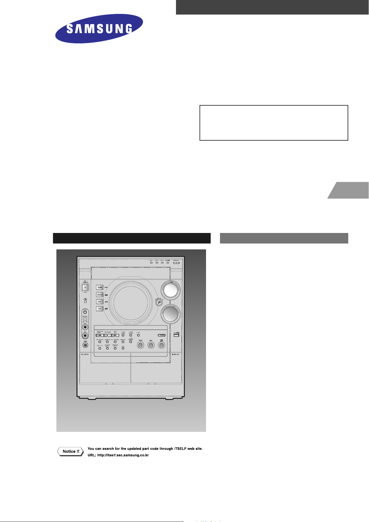
3 CD CHANGER MINI COMPONENT
SYSTEM
BASIC MODEL: MAX-DC990
SERVICE
Manual
MINI COMPONENT SYSTEM Features
* DVD/VCD/MP3-CD/ CD-R/ RW
Playback
* Tuner
* Tape Deck
- Confidential -
MODEL : MAX-DC990
* Application Model:
MAX-DC990 ,
MAX-DC990 ,
MAX-DC950
MAX-DC950
ELECTRONICS
©Samsung Electronics Co.,Ltd. AUG. 2005
Printed in Korea
Code no. AH68-01771T
Ch1 Precautions
1-1. Safety Precautions 1-1
1-2. Servicing Precautions 1-2
1-3. Precautions for Electrostatically
Sensitive Device (ESDs) 1-3
1-4. Special Precations and Waring
Lables for Laser Products 1-4
1-5. Special Precautions for HDD 1-5
INDEX
Ch2 Product Descriptions
1. Specifications 2-1
2. Notes on Discs 2-2
3. Accessories 2-3
Ch3 Product Functions
1. SPK Connection & Setup 3-1
2. Main Functions 3-2
3. New Functions 3-3
Ch4 Adjustments
Cassette Deck 4-1
Ch5 How to disassemble
How to disassemble 5-1
Ch6 Troubleshooting
1. No Power 6-1
2. No Output 6-2
3.Protection 6-3
4. DVD PACK 6-4
Ch7 Exploded View & Parts List
1. Total Exploded View 7-1
2. Parts List 7-5
Ch8 Electrical Parts List
Electrical Parts List 8-1
Ch9 Block Diagram
Block Diagram 9-1
Ch10 Wiring Diagram
Wiring Diagram 10-1
Ch11 PCB Diagram
1. MAIN 11-1
2. FRONT 11-2
Ch12 Schematic Diagram
1. MAIN 12-1
2. AMP 12-4
3. FRONT 12-5
4. POWER, MIC & HEADPHONE 12-6
5. DVD RF 12-7
6. DVD MPEG 12-8
7. DVD VIDEO 12-9
Ch13 Circuit Description
Circuit Board Description 13-1
Ch14 Reference
1. Cleaning your Component System 14-1
2. Precautions when using
the compact disc 14-2
3. Precautions when using
audio cassette 14-3
1. Precautions
Follow these safety, servicing and ESD precautions to prevent damage and protect against potential hazards
such as electrical shock and X-rays.
Samsung Electronics1-1
1-1 Safety Precautions
1. Be sure that all of the built-in protective
devices are replaced.
2. When reinstalling the chassis and its
assemblies, be sure to restore all protective
devices, including control knobs and
compartment covers.
3. Make sure that there are no cabinet
openings through which people-particularly children--might insert fingers
and contact dangerous voltages. Such
openings include the spacing between the
picture tube and the cabinet mask,
excessively wide cabinet ventilation slots,
and improperly fitted back covers.
4. Design Alteration Warning:
Never alter or add to the mechanical or
electrical design of the unit. Example: Do
not add auxiliary audio or video connectors. Such alterations might create a safety
hazard. Also, any design changes or additions will void the manufacturer's warranty.
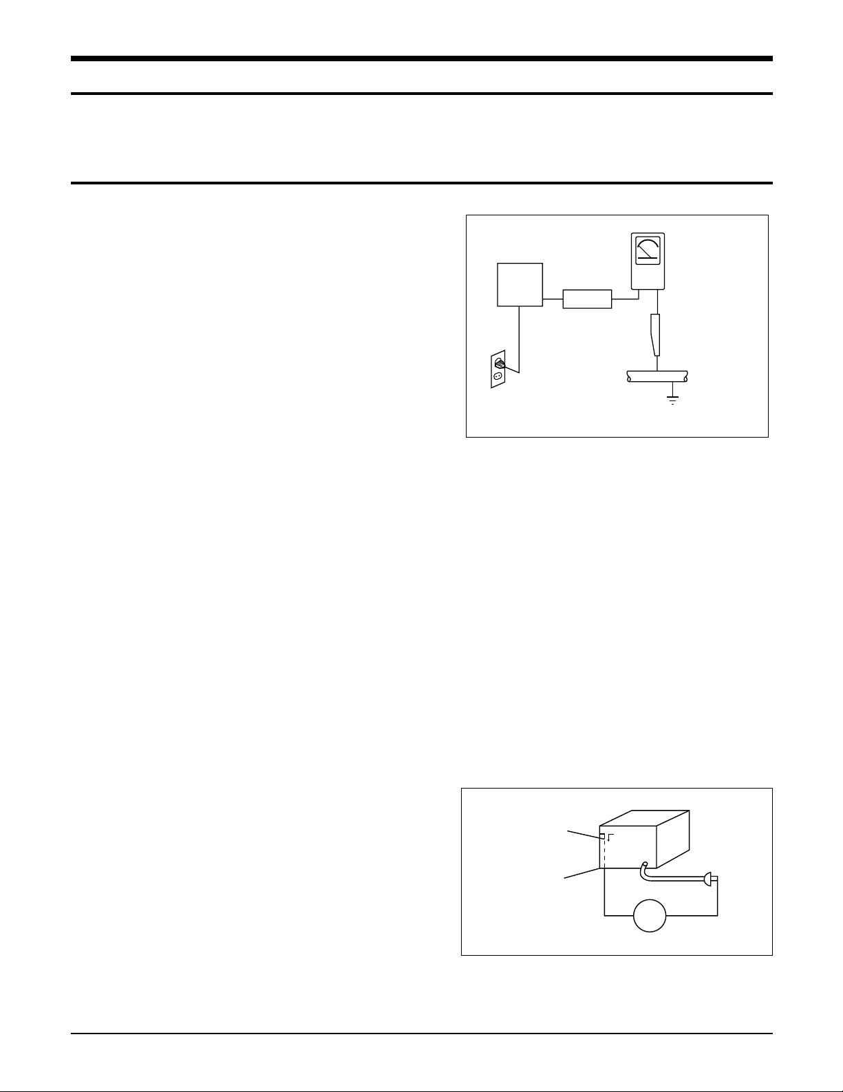
5. Leakage Current Hot Check (Figure 1-1):
Warning: Do not use an isolation
transformer during this test. Use a leakagecurrent tester or a metering system that
complies with American National Standards
Institute (ANSI C101.1, Leakage Current for
Appliances), and Underwriters Laboratories
(UL Publication UL1410, 59.7).
With the unit completely reassembled, plug
the AC line cord directly into a 120V AC
outlet. With the unit's AC switch first in
the ON position and then OFF, measure the
current between a known earth ground
(metal water pipe, etc.) and all exposed
metal parts. Examples: Handle brackets,
metal cabinets, screwheads and control
shafts. The current measured should not
exceed 0.5 milliamp. Reverse the powerplug prongs in the AC outlet and repeat.
6. Insulation Resistance Cold Check:
(1) With the unit's AC plug disconnected
from the AC source, connect an electrical
jumper across the two AC prongs. (2) Set
the power switch to ON. (3) Measure the
resistance between the shorted AC plug and
any exposed metallic parts. Example:
Screwheads, antenna, control shafts or
handle brackets.
If any of the exposed metallic parts has a
return path to the chassis, the measured
resistance should be between 1 and 5.2
megohms. If there is no return path, the
measured resistance should be "infinite." If
the resistance is outside these limits, a shock
hazard might exist. See Figure 1-2
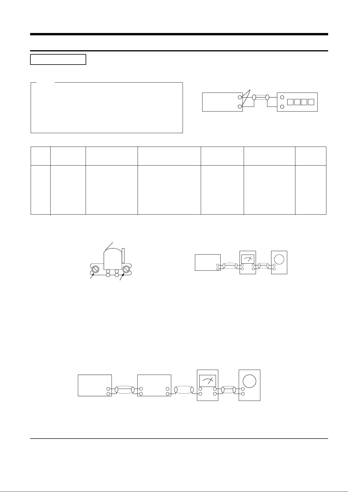
Fig. 1-1 AC Leakage Test
Fig. 1-2 Insulation Resistance Test
(Reading should
Device
Under
Test
Test all
exposed metal
surfaces
2-Wire Cord
Also test with
plug reversed
(using AC adapter
plug as required)
not be above
0.5mA)
Leakage
Currant
Tester
Earth
Ground
Antenna
Terminal
Exposed
Metal Part
ohm
Ohmmeter

Samsung Electronics 1-2
1-1 Safety Precautions (Continued)
7. Components, parts and wiring that appear
to have overheated or that are otherwise
damaged should be replaced with parts
that meet the original specifications.
Always determine the cause of damage or
overheating, and correct any potential
hazards
8. Observe the original lead dress, especially
near the following areas: Antenna
wiring, sharp edges, and especially the
AC and high voltage power supplies.
Always inspect for pinched, out-of-place,
or frayed wiring. Do not change the
spacing between components and the
printed circuit board. Check the AC
power cord for damage. Make sure that
no wires or components touch thermally
hot parts.
9. Product Safety Notice:
Some electrical and mechanical parts
have special safety-related characteristics
which might not be obvious from visual
inspection. These safety features and the
protection they give might be lost if the
replacement component differs from the
original--even if the replacement is rated
for higher voltage, wattage, etc.
10 Components that are critical for safety are
indicated in the circuit diagram by
shading, or . Use replacement
components that have the same ratings,
especially for flame resistance and
dielectric strength specifications. A
replacement part that does not have the
same safety characteristics as the original
might create shock, fire or other hazards.
1-2 Servicing Precautions
1. Servicing precautions are printed on the
cabinet. Follow them.
2. Always unplug the unit's AC power cord
from the AC power source before
attempting to: (a) Remove or reinstall any
component or assembly, (b) Disconnect an
electrical plug or connector, (c) Connect a
test component in parallel with an
electrolytic capacitor.
3. Some components are raised above the
printed circuit board for safety. An
insulation tube or tape is sometimes used.
The internal wiring may be clamped to
prevent contact with thermally hot
components. Reinstall all such elements to
their original position.
4. After servicing, always check that the
screws, components and wiring have been
correctly reinstalled. Make sure that the
portion around the serviced part has not
been damaged.
5. Check the insulation between the blades of
the AC plug and accessible conductive parts
(examples: metal panels, input terminals
and earphone jacks).
6. Insulation Checking Procedure: Disconnect
the power cord from the AC source and
turn the power switch ON. Connect an
insulation resistance meter (500V) to the
blades of the AC plug.
The insulation resistance between each
blade of the AC plug and accessible
conductive parts (see above) should be
greater than 1 megohm.
7. Never defeat any of the B+ voltage
interlocks. Do not apply AC power to the
unit (or any of its assemblies) unless all
solid-state heat sinks are correctly installed.
8. Always connect a test instrument's ground
lead to the instrument chassis ground
before connecting the positive lead; always
remove the instrument's ground lead last.
Precautions
Warning1: First read the "Safety Precautions" section of this manual. If some unforeseen circumstance creates a conflict
between the servicing and safety precautions, always follow the safety precautions.
Samsung Electronics1-3
1-3 Precautions for Electrostatically Sensitive Devices (ESDs)
1-4 Special Precautions and Warning Labels for Laser Products
1. Some semiconductor ("solid state") devices
are easily damaged by static electricity.
Such components are called Electrostatically
Sensitive Devices (ESDs). Examples include
integrated circuits and some field-effect
transistors. The following techniques will
reduce the occurrence of component
damage caused by static electricity.
2. Immediately before handling any
semiconductor components or assemblies,
drain the electrostatic charge from your
body by touching a known earth ground.
Alternatively, wear a discharging
wrist-strap device. (Be sure to remove it
prior to applying power--this is an electric
shock precaution.)
3. After removing an ESD-equipped assembly,
place it on a conductive surface such as
aluminum foil to prevent accumulation of
electrostatic charge.
4. Do not use freon-propelled chemicals.
These can generate electrical charges that
damage ESDs.
5. Use only a grounded-tip soldering iron
when soldering or unsoldering ESDs.
6. Use only an anti-static solder removal
device. Many solder removal devices are
not rated as "anti-static" (these can
accumulate sufficient electrical charge to
damage ESDs).
7. Do not remove a replacement ESD from its
protective package until you are ready to
install it. Most replacement ESDs are
packaged with leads that are electrically
shorted together by conductive foam,
aluminum foil or other conductive
materials.
8. Immediately before removing the protective
material from the leads of a replacement
ESD, touch the protective material to the
chassis or circuit assembly into which the
device will be installed.
9. Minimize body motions when handing
unpackaged replacement ESDs. Motions
such as brushing clothes together, or lifting
a foot from a carpeted floor can generate
enough static electricity to damage an ESD.
Precautions
UL : Manufactured for U.S.A. Market.
CSA : Manufactured for Canadian Market.
EU : Manufactured for European Market.
SCAN : Manufactured for Scandinavian
Market.
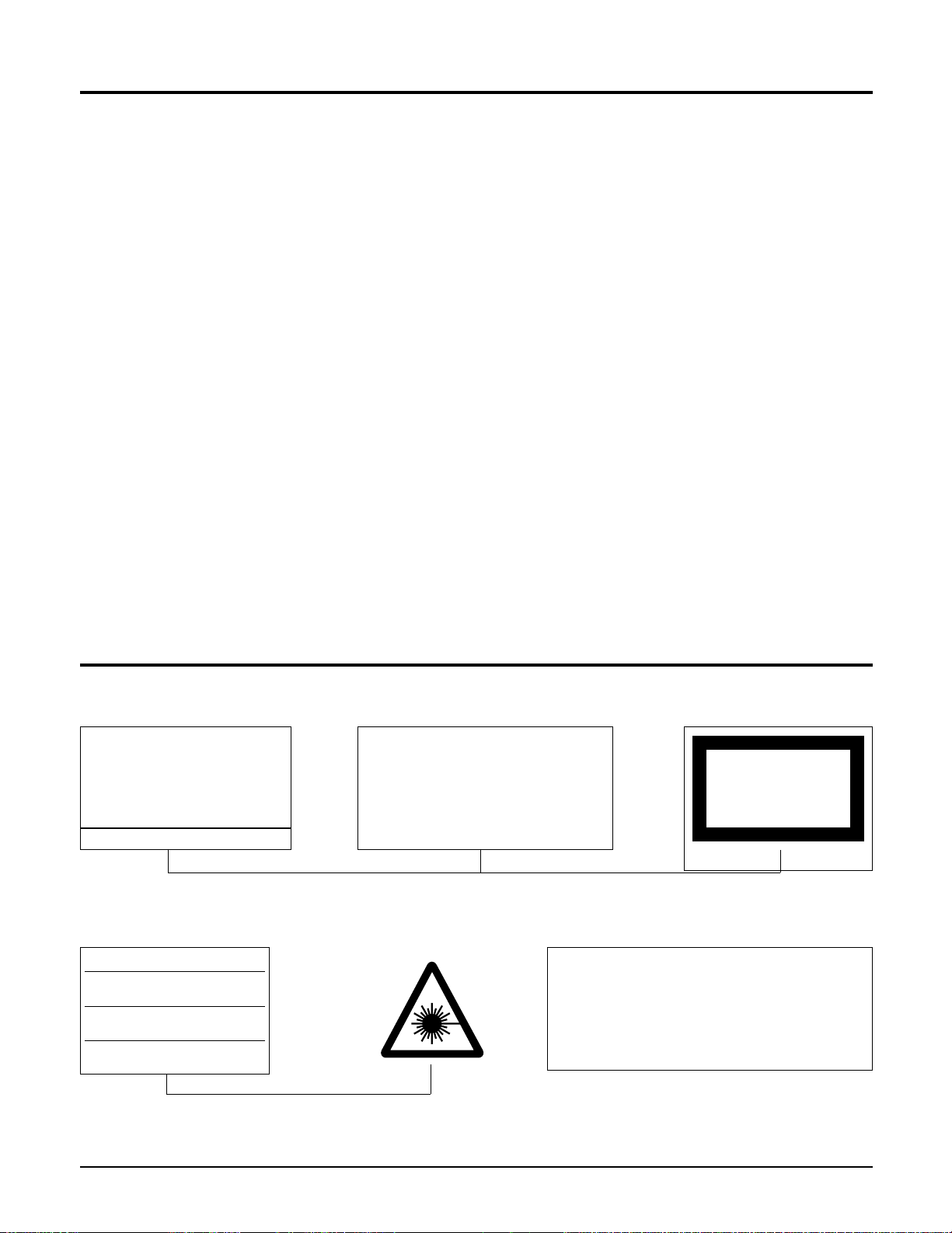
This Product Complies with
DHHS Rules 21CFR, Sub
chapter J.At date of Manufacture
(UL)
(UL,CSA,SCAN)
(EU)
CERTIFIED ONLY TO CANADIAN
ELECTRICAL CODE.
CERTIFIE EN VERTU DU CODE
CANADIAN DE LELETRICITE
SEULEMENT
(CSA)
CLASS 1
LASER PRODUCT
(UL,CSA,EU)
Fig. 1-3 Warning Labels (Location: Enclosure Block)
Fig. 1-4 Warning Labels (Location: Disc Clamper, Inner Side of Unit Door or Nearby Unit Chassis )
CAUTION :
INVISIBLE LASER RADIATION WHEN OPEN
AND INTERLOCKS DEFEATEO AVOIDEXPOSURE TO BEAM
ADVARSEL:USYNLIG LASERSTRÅLING VED ABNING
NÅR SIKKERHEDSAFBRYDERE ER UDE AF FUNKTION
UNDGA UDSAETTELSE FOR STRALING
VARO:AVATTAESSA JA SUOJALUKITUS OHITETTAESSA
OLET ALTTINA NAKYMATTÖMALLE LASERSATEILYLLE ALA
KATSO SATEESEEN!
VARNING:
OSYNLIG LASERSTRÅLNING NAR DENNA DEL
AR OPPNAD OCH SPARREN AR URKOPPLAD BETRAKTA
EJSTRÅLEN!
Samsung Electronics 1-4
1-4 Special Precautions and Warning Labels for Laser Products (Continued)
1-4-1 Warnings
1. When servicing, do not approach the LASER
exit with the eye too closely. In case it is
necessary to confirm LASER beam emission,
be sure to observe from a distance of more
than 30 cm from the surface of the objective
lens on the optical pick-up block.
2. Do not attempt to handle the objective lens
when the DISC is not on the tray.
1-4-2 Laser Diode Specifications
Material: GaAs+ GaAlAs
Wavelength: 760-800 nm
Emission Duration: Continuous
Laser Output: 0.2 mw (measured at a
1.6 mm distance from the objective lens
surface on the optical pick-up block.)
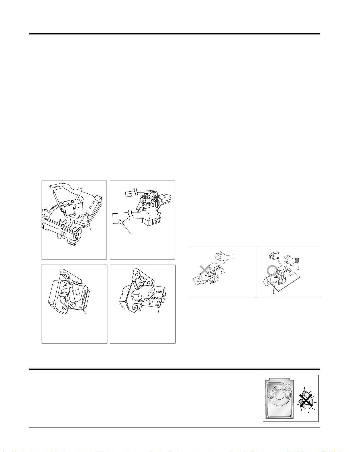
1-4-3 Handling the Optical Pick-up
1. Static electricity from clothing or the body
may cause electrostatic breakdown of the
laser diode in the Optical Pickup. Follow
this procedure:
2. Place a conductive sheet on the work bench
(i.e., the black sheet used for wrapping
repair parts.) Note: The surface of the work
bench should be covered by a copper
ground plane, which is grounded.
3. The repair technician must wear a wrist
strap which is grounded to the copper sheet.
4. To remove the Optical Pickup block:
Place the set on the conductive sheet, and
momentarily touch the conductive sheet
with both hands. (While working, do not
allow any electrostatic sources--such as
clothes--to touch the unit.)
5. Ground the "Short Terminal" (located on the
PCB, inside the Pickup Assembly) before
replacing the Pickup. This terminal should
be shorted whenever the Pickup Assembly
is lifted or moved.
6. After replacing the Pickup, reopen the Short
Terminal. See diagrams below:
Precautions
1-5 Special Precautions for HDD
* HDD Data Maintenance Step
1. Since the data on the HDD is weak to mechanical shock, place the HDD in a safe
location that is free from mechanical shock once it is removed from the main unit.
2. In order to safe keep the data on the HDD, back up the data before the repair or
make sure not to place the HDD near any electrical appliance that generates a strong
magnetic field.
short
terminal
SOH91VI(LDP)
short
terminal
SOH-A1
(CMS-V10,CMS-V30)
short terminal
SOH91CI(CAR,walkman)
short
terminal
SOH94T4N
(CMS-V10,CMS-V30)
THE UNIT
(1) WRIST-STRAP
FOR GROUNDING
1M
1M
CONDUCTIVE SHEET

Samsung Electronics 2-1
Specifications
Weight
Dimensions (W x H x D)
Operating Temperature Range
Operating Humidity Range
Usable Sensitivity
S/N Ratio
Distortion
Usable Sensitivity
S/N Ratio
Distortion
Composite Video
S-Video
Component Video
Front speaker output
Center speaker output
Rear speaker output
Subwoofer speaker output
Frequency range
S/N Ratio
Channel separation
Input sensitivity
G
E
N
E
R
A
L
T
U
N
E
R
F
M
T
U
N
E
R
A
M
O
U
T
P
U
T
V
I
D
E
O
A
M
P
L
I
F
I
E
R
13Kg
280 x 372 x 390mm
+5°C~+35°C
10%~75%
12dB
55dB
0.8%
60dB
35dB
2%
1.0Vp-p(75Ω load)
Y:1.0Vp-p(75Ω load)
Pr:0.70Vp-p(75Ω load)
Pb:0.70Vp-p(75Ω load)
130W x 2(6Ω)
130W(6Ω)
130W x 2(6Ω)
150W(4Ω)
20Hz~20kHz
70dB
55dB
(AUX)400mV
Luminance Signal : 1.0Vp-p(75Ω
Color Signal : 0.286Vp-p(75Ω load)

2-2 Samsung Electronics
2. Notes on discs
CD-R Discs
•
Some CD-R discs may not be playable depending on the disc recording device (CD-Recorder or PC) and the
condition of the disc.
•
Use a 650MB/74 minute CD-R disc.
Do not use CD-R disk over 700MB/80 minute as much as possible since it may not be played back.
•
Some CD-RW (Rewritable) media, may not be playable.
•
Only CD-Rs that are properly "closed" can be fully played. If the session is closed but the disc is left open, you
may not be able to fully play the disc.
CD-R JPEG Discs
•
Only files with the ".jpeg" and ".JPEG" extensions can be played.
•
If the disc is not closed, it will take longer to start playing and not all of the recorded files may be played.
•
Only CD-R discs with JPEG files in ISO 9660 or Joliet format can be played.
•
JPEG file names should be 8 characters or less in length and contain no blank spaces or special characters (. / = +).
•
Only a consecutively written multisession disc can be played. If there is a blank segment in the multisession disc, the
disc can be played only up to the blank segment.
•
A maximum of 9,999 images can be stored on a single CD.
•
When playing a Kodak/Fuji Picture CD, only the JPEG files in the picture folder can be played.
•
Picture discs other than Kodak/Fuji Picture CDs may take longer to start playing or may not play at all.
Disc Recording Format
CD-R MP3 Discs
•
Only CD-R discs with MP3 files in ISO 9660 or Joliet format can be played.
•
MP3 file names should be 8 characters or less in length and contain no blank spaces or special characters (. / = +).
•
Use discs recorded with a compression/decompression data rate greater than 128Kbps.
•
Only files with the ".mp3" and ".MP3" extensions can be played.
•
Only a consecutively written Multisession disc can be played. If there is a blank segment in the Multisession disc,
the disc can be played only up to the blank segment.
•
If the disc is not closed, it will take longer to begin playback and not all of the recorded files may be played.
•
For files encoded in Variable Bit Rate (VBR) format, i.e. files encoded in both low bit rate and high bit rate
(e.g., 32Kbps ~ 320Kbps), the sound may skip during playback.
•
A maximum of 500 tracks can be played per CD.
•
A maximum of 300 folders can be played per CD.

Samsung Electronics 2-3
3. Accessories
AH39-00258J CBF-POWER CORD; EP2,125V,10A,1830M
AH39-40001V CABLE-AUDIO CABLE; 1P-1P,3000MM
AH42-00018A ANTENNA-FM;T150S1F-1,1500##50m
AH42-00019A ANT LOOP;S0160BL-16,HT-DS665T,9uH,-,1KH
Code no. Description & Specification Remarks
Samsung Electronics 3-1
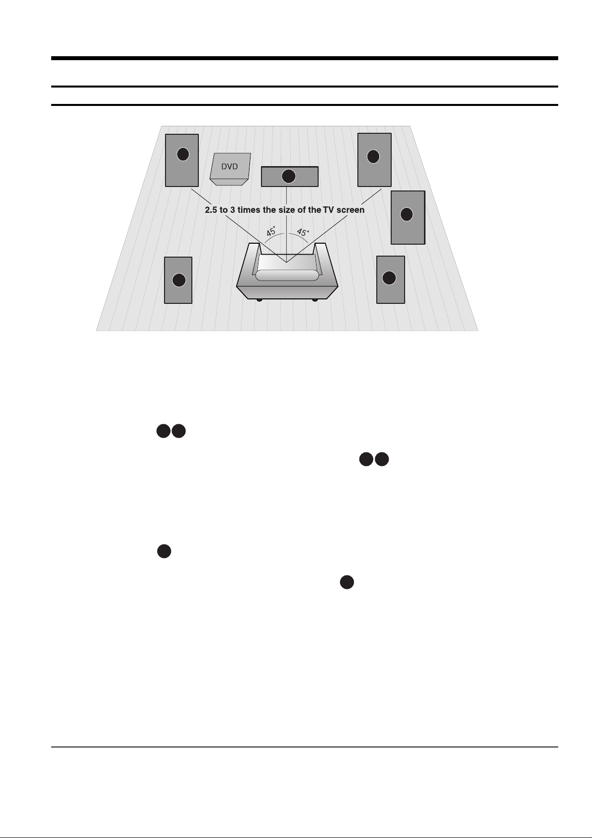
3. Product Functions
1. SPK connection
C
L
R
SW
SL
SR
Rear Speakers
•
Place these speakers behind your listening position.
•
If there isn't enough room, place these speakers to face each other.
•
Place them about 60 to 90cm (2 to 3feet) above your ear, facing
slightly downward.
*
Unlike the front and center speakers, the rear speakers are used
to handle mainly sound effects and sound will not come from
them all the time.
Subwoofer
•
The position of the subwoofer is not so critical.
Place it anywhere you like.
•
Usually, it is placed by a corner near the front speakers.
Front Speakers
•
Place these speakers in front of your listening position, facing inwards (about 45°) toward you.
•
Place the speakers so that their tweeters will be at
the same height as your ear.
•
Align the front face of the front speakers with the
front face of the center speaker or place them
slightly in front of the center speakers.
Center Speaker
•
It is best to install it at the same height as the front
speakers.
•
You can also install it directly over or under the TV.
Position of the DVD Player
•
Place it on a stand or cabinet shelf, or under
the TV stand.
Selecting the Listening Position
The listening position should be located about 2.5 to 3
times the distance of the TV's screen size away from the
TV. Example: For 32" TVs 2~2.4m (6~8feet)
For 55" TVs 3.5~4m (11~13feet)
RLC
SR
SL
SW
3-2 Samsung Electronics
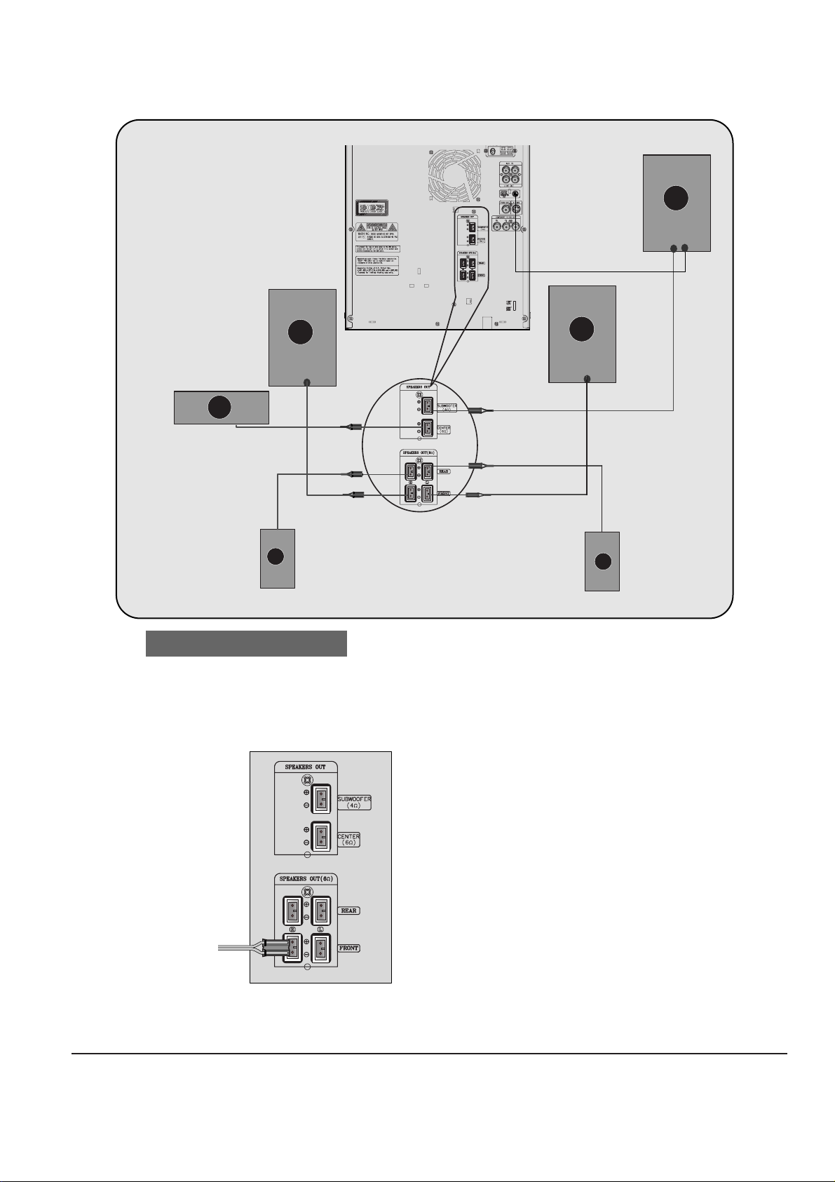
•
Make sure the colors of the speaker terminals
match the colors of the connecting jacks.
Connect the connecting jacks to
the back of the DVD player.
Back of the Main Unit
SW
Rear Speaker (R)
Front Speaker (R)
Subwoofer
Center Speaker
Rear Speaker (L)
Front Speaker (L)
Blue
Gray
Violet
Red
Green
White
R
C
SR
L
SL
Samsung Electronics 3-3
2. Main Functios
Disc Playback
•
Depending on the content of the disc, the initial screen may appear different.
•
Depending on the recording mode, some MP3-CDs cannot be played.
•
Ta ble of contents of a MP3-CD varies depending on the MP3 track format recorded
on the disc.
DVD VCD
CD
•
Playback starts automatically.
MP3 JPEG
•
Playback starts automatically.
•
If the TV is on, a list of MP3s on
the CD will appear on the TV
screen.
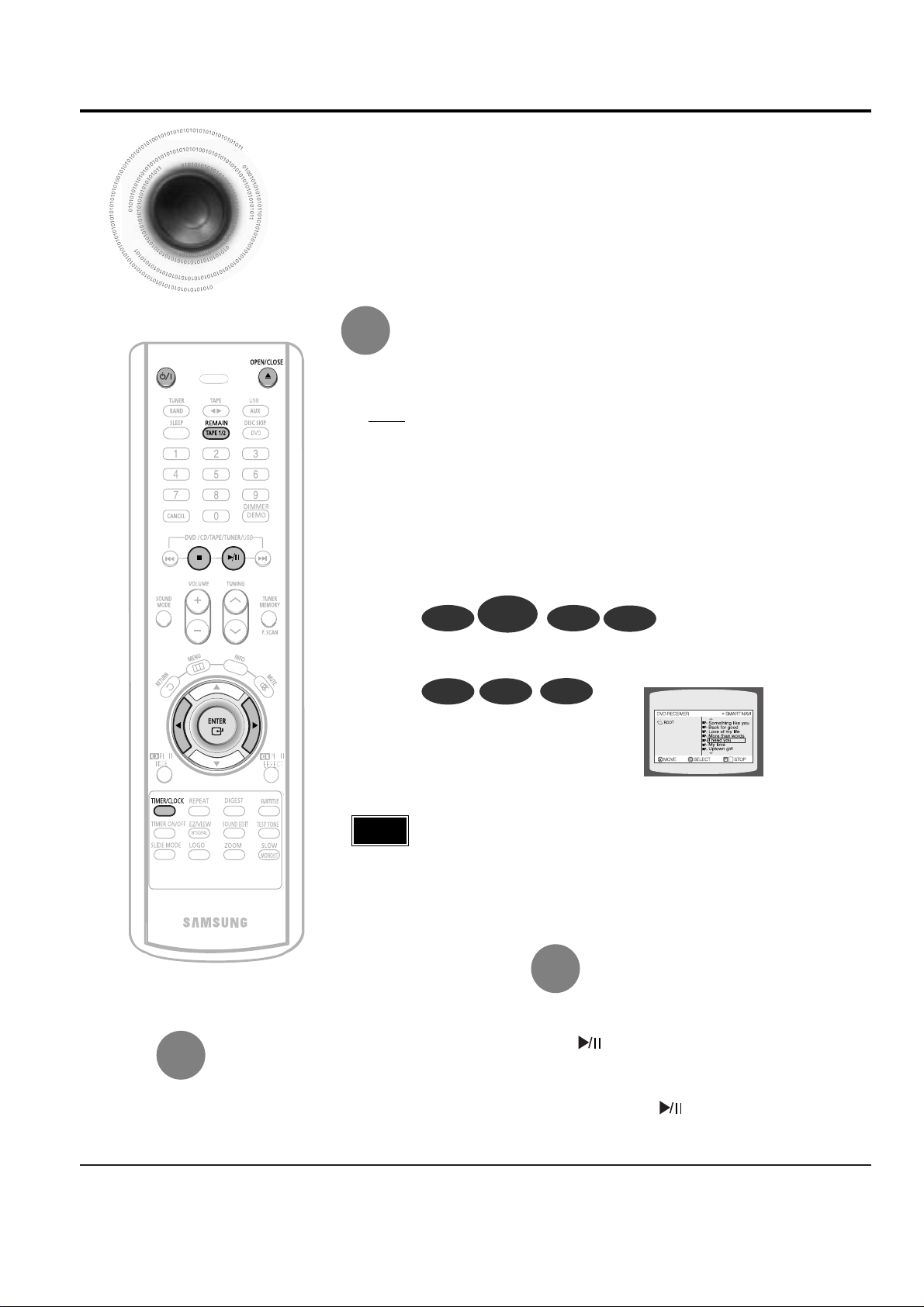
Note
•
To resume playback, press PLAY/PAUSE
button again.
To temporarily pause playback,
press PLAY/PAUSE during playback.
•
If pressed once, “PRESS PLAY” is displayed and the
stop position will be stored in memory. If PLAY/PAUSE
( ) button or ENTER button is pressed, playback
resumes from the stop position. (This function works
only with DVDs.)
•
If pressed twice, “STOP” is displayed, and if
PLAY/PAUSE ( ) button is pressed, playback
starts from the beginning.
To stop playback,
press STOP during playback.
DivX
To select a specific disc, press the corresponding DISC (1, 2, 3) button on the front panel or
DISC SKIP on the remote control, until the required disc indicator flashes.
Result: All the discs will be played in turn, starting with the one selected.
The CD function is automatically selected when Disc Skip is pushed.
Selecting a CD in the Disc changer
•
If you use the DISC (1, 2, 3) function when listening to the radio or to a tape, the
system switches automatically to the CD mode.
•
If the disc selected is not loaded, the next disc is played automatically.
DVD-
AUDIO
3-4 Samsung Electronics
•
In this manual, the instructions marked with "DVD ( )" are applicable
to DVD-VIDEO, DVD-AUDIO, and DVD-R/RW discs.
Where a particular DVD type is mentioned, it is indicated separately.
•
Depending on the content of the disc, the initial screen may appear different.
DVD
Note
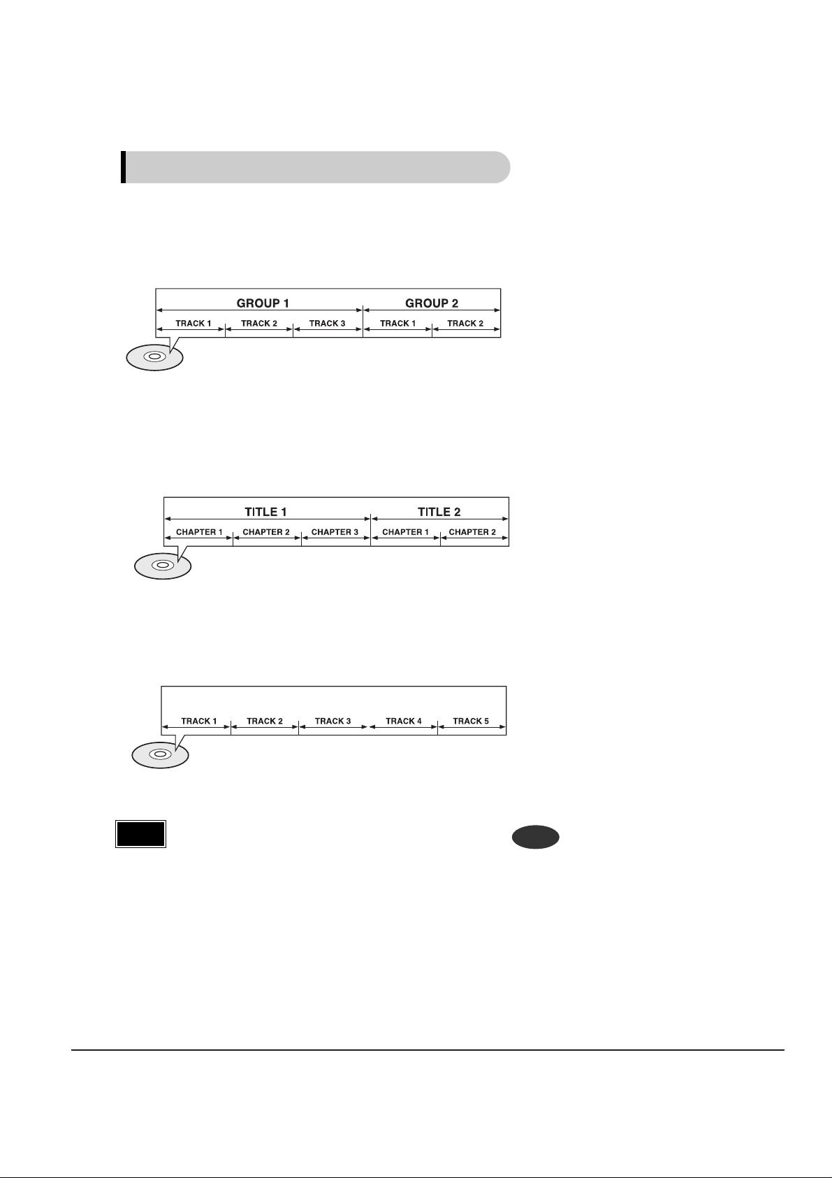
Groups and tracks (DVD-AUDIO)
•
DVD-audios are divided into several large sections called "groups" and smaller
sections called "tracks". Numbers are allotted to these sections.
These numbers are called "group numbers" and "track numbers".
Titles and chapters (DVD-VIDEO)
•
DVD-videos are divided into several large sections called "titles" and smaller sections called "chapters". Numbers are allotted to these sections.
These numbers are called "title numbers" and "chapter numbers".
Tracks (Video and music CDs)
•
Video and music CDs are divided into sections called "tracks".
Numbers are allotted to these sections. These numbers are called "track numbers".
Disc terminology
Samsung Electronics 3-5
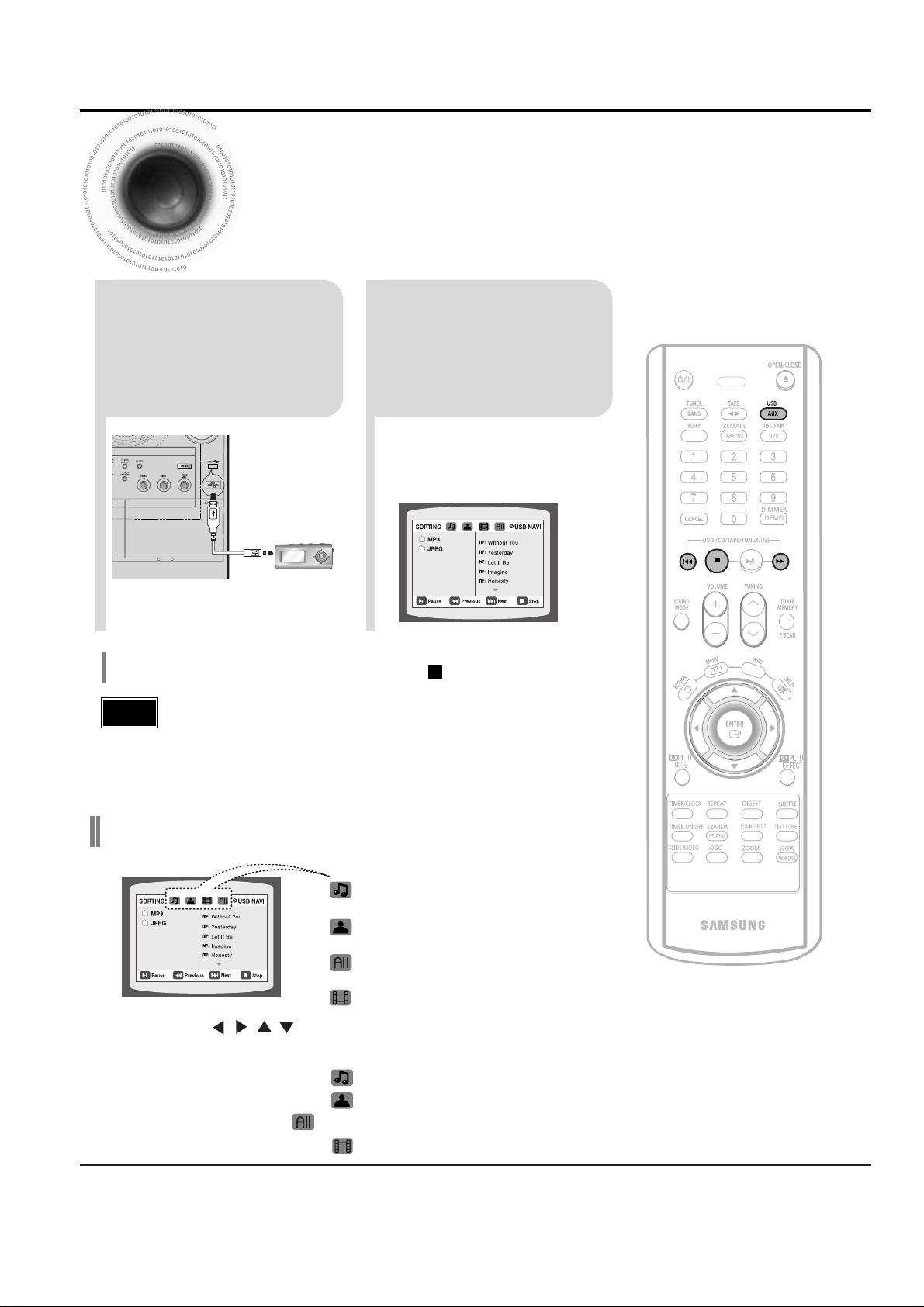
3. New Functions
•
Video files (DivX, WMV, MPEG, etc.) are supported.
•
To prevent the loss of data saved in the USB device, please turn the unit off or
switch it to another mode before disconnecting the USB cable.
•
Music File Icon
•
Image File Icon
•
All File Icon
•
Movie File Icon
Note
2
Press the USB button
on the main unit or
the AUX button on the
remote control to
select the USB mode.
•
“USB” appears on the display screen
and then disappear.
•
USB SORTING screen appears on the
TV screen and the saved file is played.
1
connect the USB
cable.
Press the button when it is in stop status and
select a desired icon from the top part of the menu.
•
To play music files only, select the Icon.
•
To view image files only, select the Icon.
•
To select all files select the Icon.
•
To view movie files only, select the Icon.
You can connect and play files from external USB storage devices such as MP3 players, USB flash memory,
etc. using the player's USB function.
To stop playback, press the STOP ( ) button.
To play a file in the USB menu screen,
Playing Media Files using the USB feature
3-6 Samsung Electronics
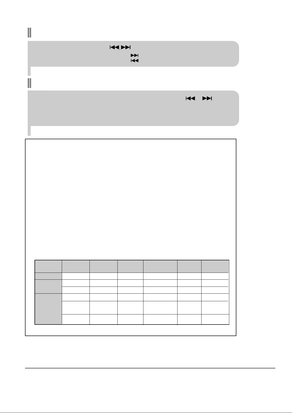
Fast playback
Skip Forward/Back
During playback, press the button.
•
When there is more than a file, when you press the button, the next file is selected.
•
When there is more than a file, when you press the button, the previous file is selected.
To playback the disc at a faster speed, press and hold or
during playback.
•
Each time you press and hold either button, the playback speed will change as follows:
2x ➞ 4x ➞ 8x ➞ 32x ➞ Normal.
Compatible Devices
1. USB devices that support USB Mass Storage v1.0.
(USB devices that operate as a removable disk in Windows
(2000 or later) without additional driver installation.)
2. MP3 Player: HDD and flash type MP3 player.
3. Digital camera: PTP protocol is not supported.
•
Devices which require additional program installation when you have connected it to a computer, are not
supported.
4. USB HDD and USB Flash Drive: Devices that support USB2.0 or USB1.1.
•
You may experience a difference in playback quality when you connect a USB1.1 device.
•
For a USB HDD, make sure to connect an auxiliary power cord to the USB HDD for proper operation.
5. USB card Reader: One slot USB card reader and Multi slot USB card reader
•
Depending on the manufacturer. the USB card reader may not be supported.
•
If you install multiple memory devices into a multi card reader, you may experience problems.
File name
File
Bit rate Version Pixel
Sampling
extension Frequency
Still Picture JPG .JPG .JPEG – – 640*480 –
Music
MP3 .MP3 80~384kbps – – 44.1kHz
WMA .WMA 56~128kbps V8 – 44.1kHz
Movie
VCD MPG.MPEG .DAT 1.5Mbps VCD1.1,VCD2.0 320*480
44.1KHz
WMV .WMV 4Mbps V1,V2,V3,V7 720*480
44.1KHz~48KHz
●
Supported Formats
•
A device using NTFS file system is not supported.(Only FAT file system is supported.)
The USB host function of this product does not support all USB devices.
For the information on the supported devices,pls see the P78
Samsung Electronics 4-1
4. Adjustments
(GND)
VTVM
1. To Adjust Tape Speed
1) Measuring tape: i) MTT-111 (or equivalent)
(Tapes recorded with 3kHz)
ii) MTT-5512 (or equivalent)
2) Connect the SPK OUT of the MAIN PCB to the fre-
quency counter as in figure 1-5.
Notes
NOR
SPEED
Control
1
SPK OUT
(connected
to the frequency
counter)
Fixed
3KHz
Remark
Standard
To Adjust
Pre-Setup
Item
Step
Pre-Setup
Condition
1) Deck :MTT-111
2) Press PLAY
SW button
SPK OUT
Figure 1-7
In Out
MAIN PCB
Oscilloscope
±1%
range
Figure 1-8
Audio OSC.
SET
(MAIN PCB)
Oscilloscope
AUX IN
VTVM
IN
SPK OUT
IN OUT
TP
Figure 1-6
Recording /Play head
AZIMUTH control screw
(RVS Play)
AZIMUTH control screw
(FWD Play)
MAIN PCB
output
SPK OUT
Frequency Counter
Figure 1-5
Cassette Deck
4-2 Samsung Electronics
1) Before the actual adjustment, clean the play/recording
head.
2) Measuring tape :
i) MTT-114N(or equivalent 10kHz AZIMUTH control)
ii) MTT-5512
3) The cassette deck is connections as shown in figure 1-7.
Notes
AZIMUTH
1
SPK OUT
(VTVM is
connected to
the scope)
- Turn the control
screw to as shown
in Figure 1-6.
Max output
and same phase
(both channels)
After
adjustment
secure it with
REGION
LOCK.
Remark
Standard
To Adjust
Pre-Setup
Item
Step
Pre-Setup
Condition
After putting MTT-
114N into Deck 1
- Press FWD PLAY
button.
1
2
- Turn the control
screw to as shown in
Figure 1-6.
MAX OUTPUT
and same phase
(both channels)
CHECK TO
7mV(±0.5mV)
Remark
Standard
To Adjust
Pre-Setup
Item
Step
Pre-Setup
Condition
After putting MTT-
5512 into Deck 2
1) Press REC PLAY button.
2) TAPE PCB JCW3 ,connected
to VTVM
Recording
Bias
Voltage
2. To Adjust PlayBack Level/REC
2. Adjust Deck 2 Play Level/ REC BIAS
1. Adjust Deck 1 Play Level
AZIMUTH
SPK OUT
(VTVM is con-
nected to the
scope)
Fig 1-8
- Turn JSR2L,JSR2R
to the right and left
After adjustment secure
it with
REGION
LOCK.
After putting MTT-
114N into Deck 2
- Press FWD PLAY
button.
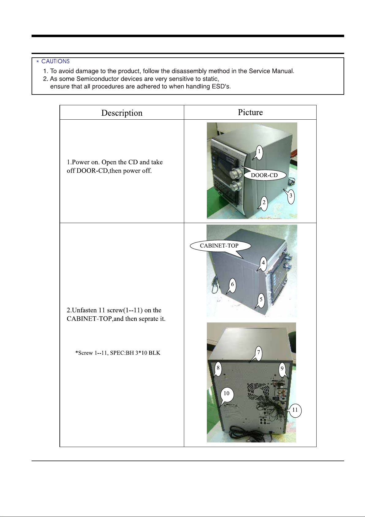
Samsung Electronics 5-1
5. How to disassemble
 Loading...