

SAMSUNG MAX75sef, MAX72, MAXN75SESA Schematics
1-1Samsung Electronics
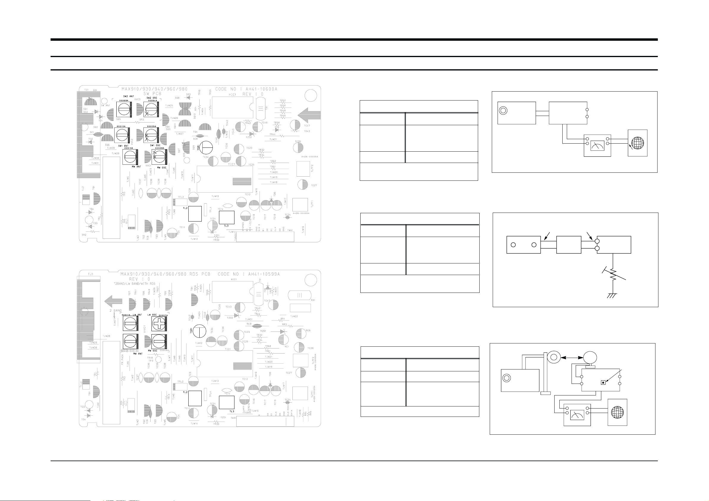
1. Alignment and Adjustments
1-1 Tuner
FM THD Adjustment
Output
Output
23 dB
60 dB
Minumum Distortion (0.3% below)
(Figure 1-1)
SSG FREQ.
Adjustment
point
(TL3)
98 MHz
FM DETECTOR COIL
FM Search Level Adjustment
Adjust TSR1 so that “TUNED” of FLT
is lighted (Figure 1-2)
Figure1-2 FM Auto Search Level Adjustment
*Adjust FM S.S.G level to 23dB
Figure1-1 IF CENTER and THD Adjustment
SSG FREQ.
Adjustment
point
(TSR1)
98 MHz
BEACON
SENSITIVITY
SEMI-VR(5KΩ)
FM S.S.G
GND
23 dB
FM S.S.G
Output
GND
Speaker
Terminal
FM
Antenna
Terminal
Distortion Meter
Input
SET
Input
output
Oscilloscope
FM IN
FM Antenna
SET
5 kΩ
OUTPUT
AM SSG
450KHZ
INPUT
AM ANT
IN
Speaker Terminal
60cm
TL2
VTVM Oscilloscope
AM(MW) I.F Adjustment
Maximum output (Figure 1-3)
SSG FREQ.
Frequency
Adjustment
point
(TL2)
450 kHz
522 kHz
AM I.F COIL
Figure1-3 AM I.F Adjustment
OUTPUT
* Adjustment Location of SW Band
* Adjustment Location of LW Band
Alignment and Adjustments
1-2 Samsung Electronics
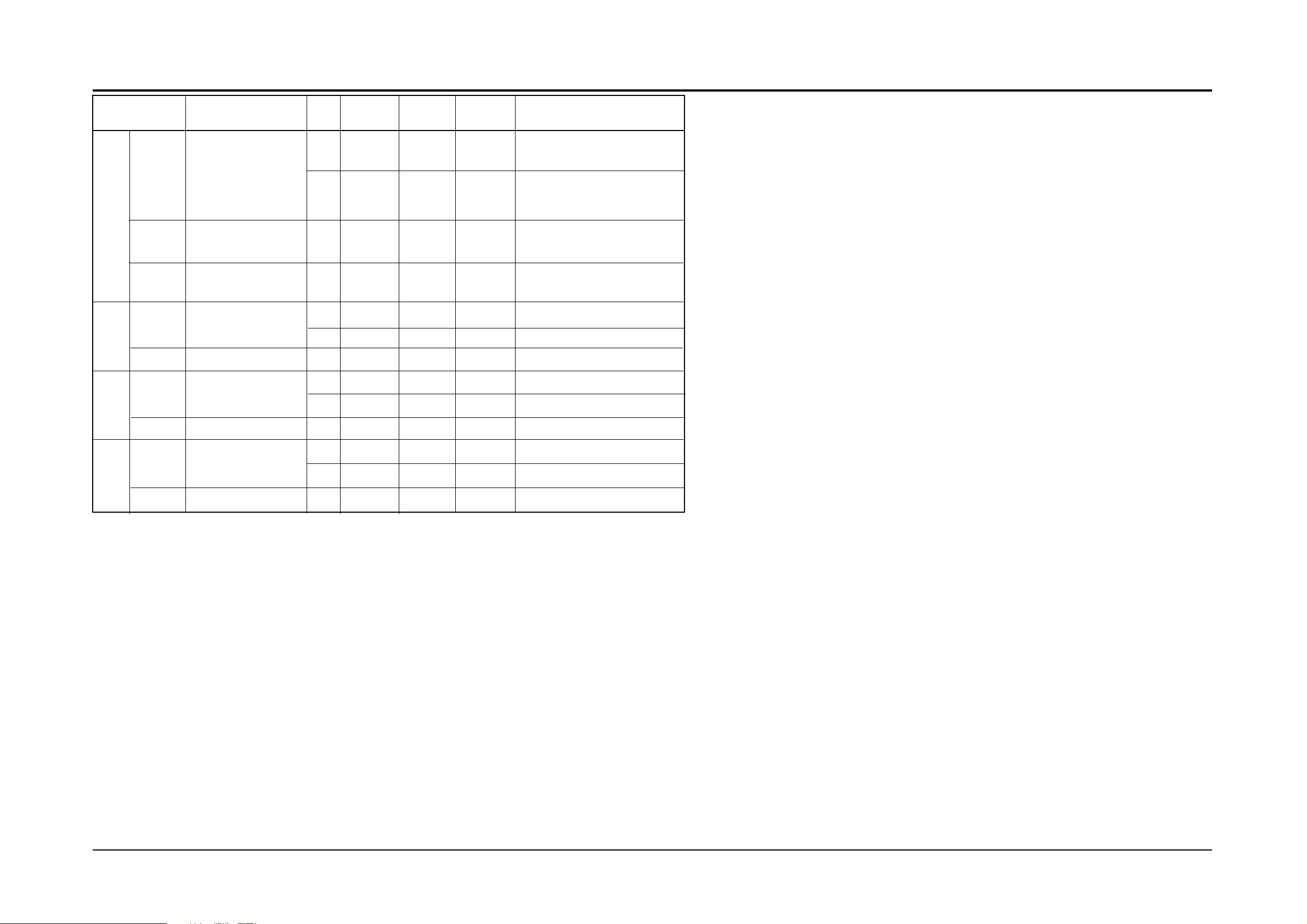
1-1-2 AM(MW),LW,SW1,SW2 Adjustment
Circuit Measuring Instrument & Step S.S.G Radio dial Adjusting Adjust for
to be Arrangement Frequency Setting Point
Adjusted
1 522KHz 522KHz MW OSC Aduust for 1.0V±0.1V at the low.
OSC Connect AM signal (IR117)
generator to loop
antenna,VTVM AND
oscilloscope 2 1611KHz 1611KHz MW OSC
Check for 7.0V±1.0V at the high.
(Fig 1-3) (IR117)
AM
(MW)
RF “ 1 594KHz 594KHz MW ANT Maximum out
INTER FREQ “ 1 455KHz 522KHz TL2 Maximum out
OSC Fig 1-3 1 146KHz LW OSC Aduust for 2.0V±0.1V at the low.
LW 2 290KHz LW OSC Check for 7.0V±1.0V at the high.
RF 1 150KHz 150KHz LW ANT Maximum out
OSC Fig 1-3 1 2.3MHz SW1 OSC Aduust for
1.0V±0.1V at the low.
SW1 2 7.3MHz -
Check for 8.5V±1.0V at the high.
RF 1 3.5MHz 3.5MHz SW1 ANT Maximum out
OSC Fig 1-3 1 9.5MHz SW2 OSC Aduust for 1.5V±0.1V at the low.
SW2 2 26.1MHz - Check for 8.0V±1.0V at the high.
RF 1 10MHz 10MHz SW2 ANT Maximum out
 Loading...