

Page 1
1-1Samsung Electronics
1. Alignment and Adjustments
1-1 Tuner
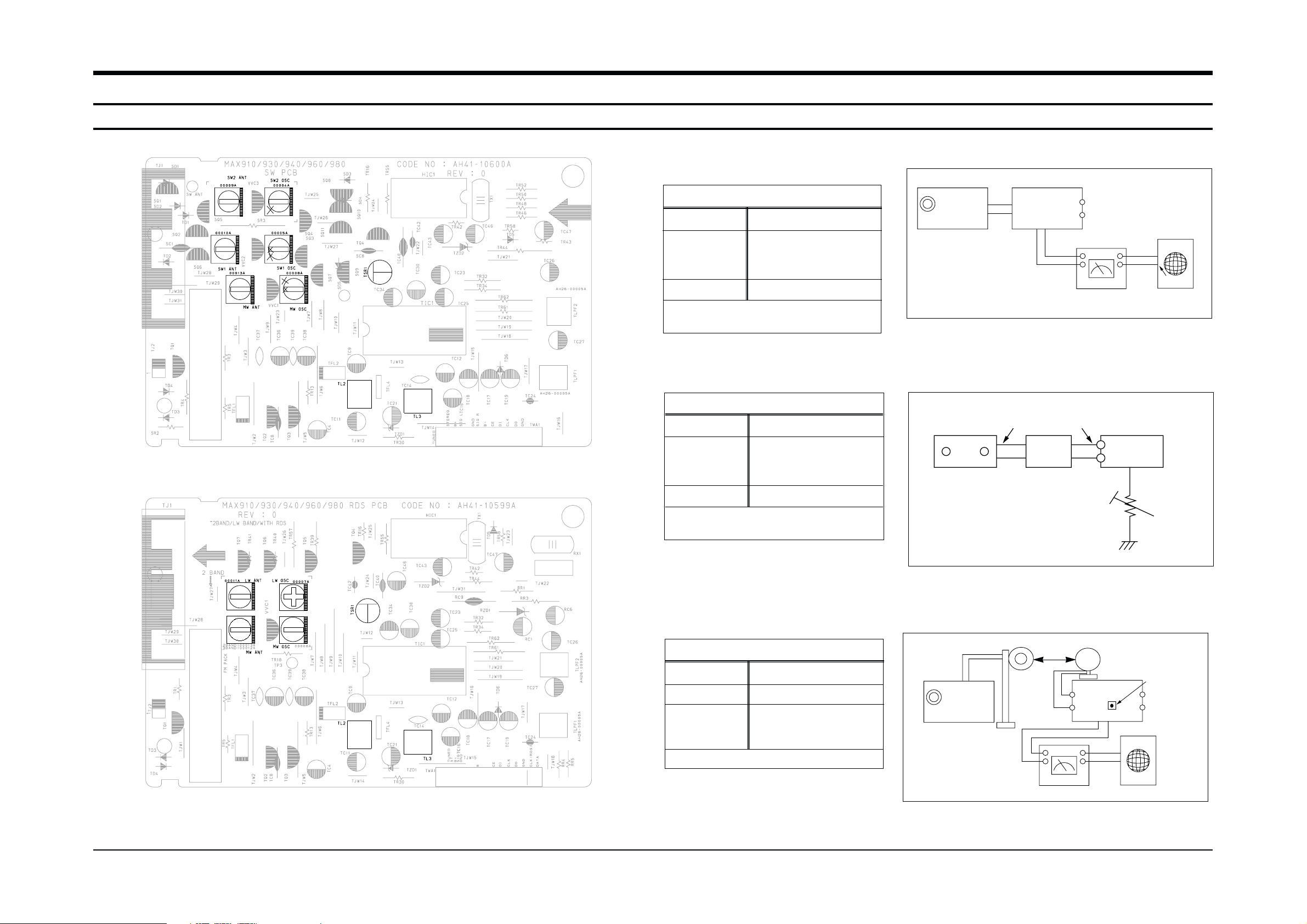
FM THD Adjustment
Output
Output
23 dB
60 dB
Minumum Distortion (0.3% below)
(Figure 1-1)
SSG FREQ.
Adjustment
point
(TL3)
98 MHz
FM DETECTOR COIL
FM Search Level Adjustment
Adjust TSR1 so that “TUNED” of FLT
is lighted (Figure 1-2)
Figure1-2 FM Auto Search Level Adjustment
*Adjust FM S.S.G level to 23dB
Figure1-1 IF CENTER and THD Adjustment
SSG FREQ.
Adjustment
point
(TSR1)
98 MHz
BEACON
SENSITIVITY
SEMI-VR(5KΩ)
FM S.S.G
GND
23 dB
FM S.S.G
Output
GND
Speaker
Terminal
FM
Antenna
Terminal
Distortion Meter
Input
SET
Input
output
Oscilloscope
FM IN
FM Antenna
SET
5 kΩ
OUTPUT
AM SSG
450KHZ
INPUT
AM ANT
IN
Speaker Terminal
60cm
TL2
VTVM Oscilloscope
AM(MW) I.F Adjustment
Maximum output (Figure 1-3)
SSG FREQ.
Frequency
Adjustment
point
(TL2)
450 kHz
522 kHz
AM I.F COIL
Figure1-3 AM I.F Adjustment
OUTPUT
* Adjustment Location of SW Band
* Adjustment Location of LW Band
Page 2

Alignment and Adjustments
1-2 Samsung Electronics
1-1-2 AM(MW),LW,SW1,SW2 Adjustment
Circuit Measuring Instrument & Step S.S.G Radio dial Adjusting Adjust for
to be Arrangement Frequency Setting Point
Adjusted
1 522KHz 522KHz MW OSC Aduust for 1.0V±0.1V at the low.
OSC Connect AM signal (IR117)
generator to loop
antenna,VTVM AND
oscilloscope 2 1611KHz 1611KHz MW OSC
Check for 7.0V±1.0V at the high.
(Fig 1-3) (IR117)
AM
(MW)
RF “ 1 594KHz 594KHz MW ANT Maximum out
INTER FREQ “ 1 455KHz 522KHz TL2 Maximum out
OSC Fig 1-3 1 146KHz LW OSC Aduust for 2.0V±0.1V at the low.
LW 2 290KHz LW OSC Check for 7.0V±1.0V at the high.
RF 1 150KHz 150KHz LW ANT Maximum out
OSC Fig 1-3 1 2.3MHz SW1 OSC Aduust for
1.0V±0.1V at the low.
SW1 2 7.3MHz -
Check for 8.5V±1.0V at the high.
RF 1 3.5MHz 3.5MHz SW1 ANT Maximum out
OSC Fig 1-3 1 9.5MHz SW2 OSC Aduust for 1.5V±0.1V at the low.
SW2 2 26.1MHz - Check for 8.0V±1.0V at the high.
RF 1 10MHz 10MHz SW2 ANT Maximum out
Page 3
Alignment and Adjustments
1-3Samsung Electronics
(GND)
VTVM
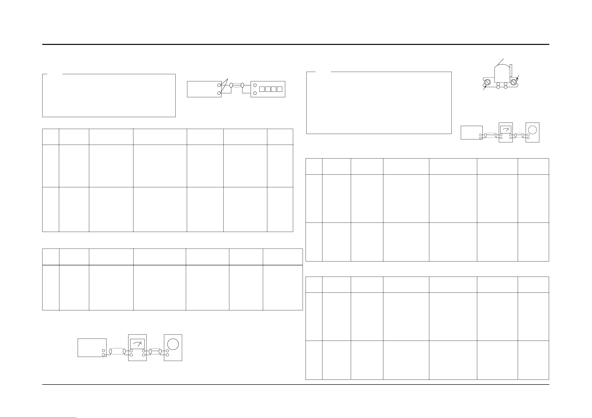
1-2-1 To Adjust Tape Speed
1) Measuring tape: i) MTT-111 (or equivalent)
(Tapes recorded with 3kHz)
ii) MTT-5512 (or equivalent)
2) Connect the cassette deck to the frequency counter
as in figure 1-4.
1) Before the actual adjustment, clean the play/recording
head.
2) Measuring tape :
i) MTT-114NA(or equivalent 12.5kHz AZIMUTH control)
ii) MTT-150(or equivalent : Dolby level 200nwb/m)
3) Dolby NR SW OFF
4) The cassette deck is connections as shown in figure 1-6.
Notes
Notes
NOR
SPEED
Control
1
2
OUT
(connected
to the frequency
counter)
Turn CVR1 to
left and right
3KHz
6KHz
Turn CVR2
to left and
right
Remark
Standard
To Adjust
Pre-Setup
Item
Step
Pre-Setup
Condition
Same as above
1) Deck 1:MTT-111
2) Press PLAY
SW button
3) Deck 2:Same
as above
1) Deck 1:MTT-111
2) Deck 2:MTT-5512
3) Press DUBBING
SW button two times.
HI SPEED
Control
AZIMUTH
1
2
TP1 OUT
(VTVM is
connected to
the scope)
1) Turn the control
screw to as shown
in Figure 1-5.
2) Adjust the right
control screw to
playback REV. Mode
Max output
and same phase
(both channels)
After
adjustment
secure it with
REGION
LOCK.
Adjust to level
and same Aux
level.
L-CH:Turn JSR2L
to the right and
left
R-CH:Turn J SR2R to
the right and left
See the
diagram for
adjustment
locations.
Remark
Standard
To Adjust
Pre-Setup
Item
Step
Pre-Setup
Condition
Same as
above
After putting MTT-
114NA into Deck 1
1) Press FWD PLAY
button.
2) Press REV PLAY
button.
PLAY MTT-150
on Deck 1.
PlayBack
out Level
AZIMUTH
1
2
TP1 OUT
(VTVM is
connected to
the scope)
1) Turn the control
screw to as shown
in Figure 1-5.
2)Adjust the right
control screw to
playback REV. Mode
Max output
and same phase
(both channels)
After
adjustment
secure it with
REGION
LOCK.
Adjust to level
and same Aux
level.
L-CH:Turn JSR3L
to the right and
left
R-CH:Turn JSR3R to
the right and left
See the
diagram for
adjustment
locations.
Remark
Standard
To Adjust
Pre-Setup
Item
Step
Pre-Setup
Condition
Same as
above
After putting MTT-
114NA into Deck 2
1)Press FWD PLAY
button.
2)Press REV PLAY
button.
PLAY MTT-150
on Deck 2.
PlayBack
out Level
1-2-2 To Adjust PlayBack Level
@ Adjust Deck 2 Play Level
! Adjust Deck 1 Play Level
Cassette Deck
output
SPK OUT
Frequency Counter
Figure 1-4
Figure 1-5
SPK OUT
Recording /Play head
FWD PLAY
REVERSE PLAY
AZIMUTH control screw
Figure 1-6
In Out
Cassette Deck
Oscilloscope
1-2 Cassette Deck
Fig1-8
Fig1-8
To Adjust Recording Level
1
See diagram
for adjustment
locations
25 mV
L-CH: JSR1L and
R-CH: JSR1R to
the right and left
To Adjust
Standard
Remark
Pre-Setup
Item
Step
Pre-Setup
Condition
Connect to
JCW2 as in Figure
1-7 and read the
VTVM
Insert MTT-5512 into
Deck2, then press
REC button.
BIAS
Electric
current
Figure 1-7
Audio OSC.
Cassette Deck
Oscilloscope
AUX IN
SPK OUT
VTVM
IN
JCW2
IN OUT
 Loading...