

Page 1
4. Disassembly and Reassembly
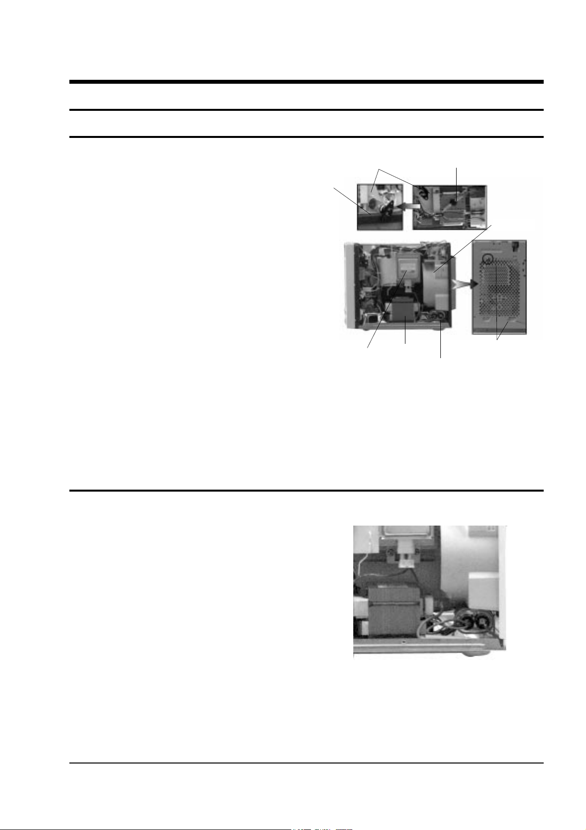
4-1 Replacement of Magnetron, Motor Assembly and Lamp
Samsung Electronics 4-1
Remove the magnetron including the shield case,
permanent magnet, choke coils and capacitors (all
of which are contained in one assembly).
1. Disconnect all lead wires from the magnetron
and lamp.
2. Remove a screw securing the magnetron
supporter.
3. Remove the thermostat.
4. Remove the air cover.
5. Remove screws securing the magnetron to the
wave guide.
6. Take out the magnetron very carefully.
7. Remove screws from the back panel.
8. Take out the fan motor.
9. Remove the oven lamp by rotating to pull out
from hole of air cover.
NOTE1: When removing the magnetron, make
sure that its antenna does not hit any
adjacent parts, or it may be damaged.
NOTE2: When replacing the magnetron, be sure
to remount the magnetron gasket in
the correct position and make sure the
gasket is in good condition.
1. Discharge the high voltage capacitor.
2. Disconnect all the leads.
3. Remove the mounting bolts.
4. Reconnect the leads correctly and firmly.
4-1 Replacement of High Voltage Transformer
Lamp
Magnetron
H. V. Trans
H. V. Capacitor
Screw
Thermo S/WCover Air
Fan Motor
Page 2
4-3 Replacement of Door Assembly
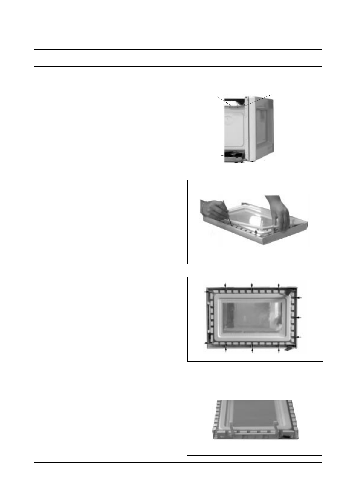
4-3-1 Removal of Door Assembly
4-2 Samsung Electronics
Remove hex bolts securing the upper hinge and
lower hinge. Then remove the door assembly.
Insert flat screwdriver into the gap between Door
"E" and Door "C" to remove Door "C". Be careful
when handling Door "C" because it is fragile.
Following the procedure as shown in the figure,
insert and bend a thin metal plate between Door
"E" and Door "A" until you hear the 'tick' sound.
1. Insertion depth of the thin metal plate should be
0.5mm or less.
Remove pin hinge from Door "E"
Detach spring from Door "E" and key door.
4-3-2 Removal of Door "C"
4-3-3 Removal of Door "E"
Disassembly and Reassembly
Upper Hinge
Lower Hinge
Screws
Screws
4-3-4 Removal of Key Door & Spring
Key Door Spring
Door "E"
Page 3
4-3-5 Reassembly Test
Samsung Electronics 4-3
1. Disconnect the oven from the power source.
2. Remove the 10A fuse in the fuse holder.
3. When replacing the 10A fuse, be sure to use an
exact replacement part. If new 10A fuse blows
out again after replacement, check the primary
interlock switch, door sensing switch and
interlock monitor switch.
4. When the above three switches operate properly,
check if any other part such as the control circuit
board, blower motor or high voltage
transformer is defective.
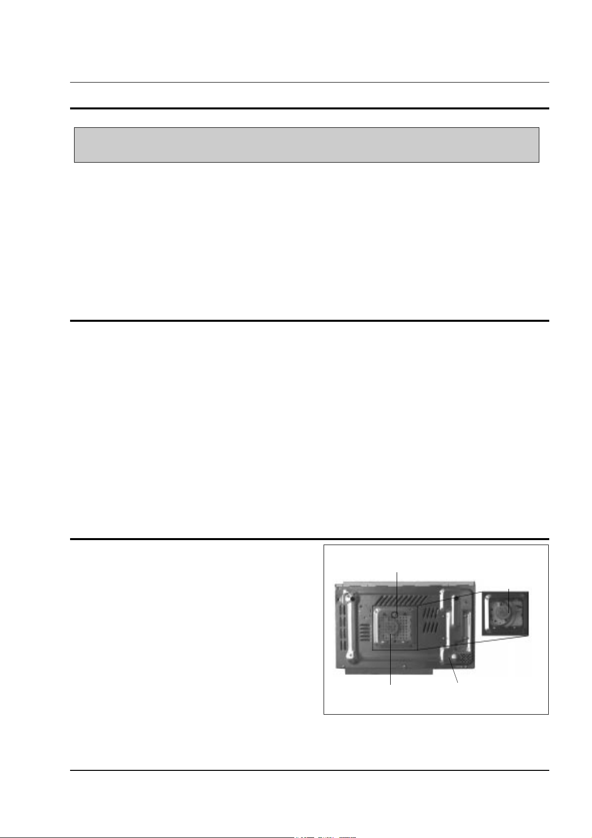
1. Take out the glass tray, guide roller and coupler
from cavity.
2.
Turn the oven upside down to replace the drive motor.
3. Remove a screw securing the drive motor cover.
4. Disconnect all the lead wires from the drive motor.
5. Remove screws securing the drive motor to the
cavity.
6. Remove the drive motor.
7. When replacing the drive motor, be sure to
remount it in the correct position.
8. Connect all the leads to the drive motor.
9. Screw the deive motor cover to the base plate
with a screw driver.
10. Remount the coupler in the correct position.
4-4 Replacement of Fuse
4-5 Replacement of Drive Motor
Disassembly and Reassembly
Screw
Drive Motor Cover
Base Plate
Drive Motor
After replacement of the defective component parts of the door, reassemble it and follow the instructions below for proper
installation and adjustment so as to prevent an excessive microwave leakage.
1. When mounting the door to the oven, be sure to adjust the door parallel to the bottom line of the oven
face plate by moving the upper hinge and lower hinge in the direction necessary for proper alignment.
2. Adjust so that the door has no play between the inner door surface and oven front surface. If the door
assembly is not mounted properly, microwave energy may leak from the space between the door and
oven.
3. Do the microwave leakage test.
Page 4
4-6 Replacement of Control Circuit Board
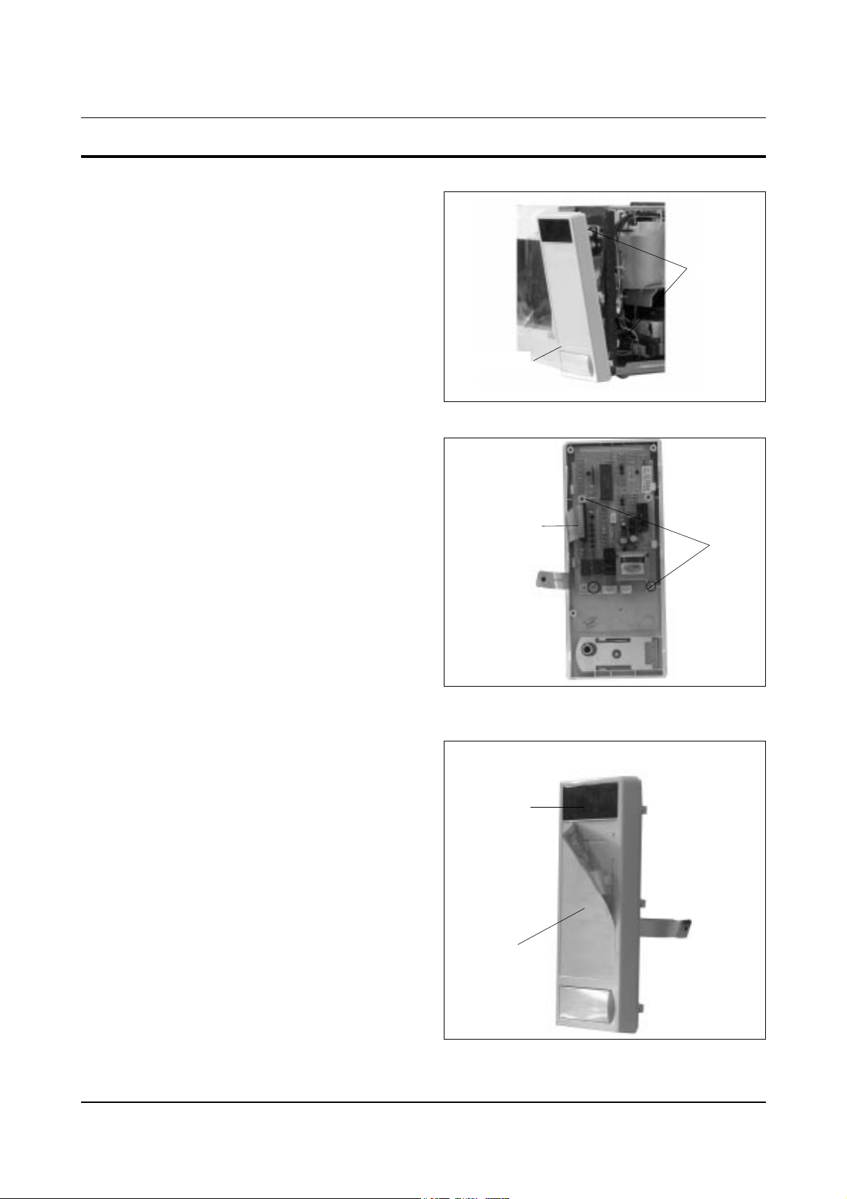
4-6-1 Removal of Ass'y Control Box
4-4 Samsung Electronics
1. Be sure to ground any static electric charge in
your body and never touch the touch control
circuitry.
2. Disconnect the connectors from the control
circuit board.
3. Remove screws securing the control box
assembly.
4. Remove the screw securing the ground tail of
the keyboard.
1. Pull the lever end of the plastic fastener and
remove the Flexible Printed Circuit(FPC) of
membrane panel.
2. Remove screws securing the control circuit
board.
3. Lift up the control circuit board from the Ass'y
control box.
4. When reconnecting the FPC connector, make
sure that the holes on the connector are properly
engaged with the hooks on the Plastic Fastener.
1. Window display should not be disassembled as
its mounting tabs will be broken. If repair work
is difficult, replace with Ass'y control panel.
2. The membrane key board is attached to the
escutcheon base with doublefaced adhesive
tape. Therefore, applying hot air such as using
of hair dryer is recommended for smoother
removal.
3. When installing new membrane key board,
make sure that the surface of escutcheon base is
cleaned sufficiently so that any problems
(shorted contacts or uneven surface) can be
avoided.
4-6-2 Remonal of Ass'y P.C.B
4-6-3 Removal of Window Display & Membrane Panel
Disassembly and Reassembly
Control Box
FPC Connector
Screw
Screw
Membrane
Panel
Windwo
Display
 Loading...