

Page 1
320+520-E 7/21/98 11:33 AM Page i
Color Monitor
Owner’s
Instructions
Page 2
320+520-E 7/21/98 11:33 AM Page ii
RISK OF ELECTRIC SHOCK
CAUTION: TO REDUCE THE RISK OF ELECTRIC SHOCK,
DO NOT REMOVE COVER (OR BACK).
NO USER-SERVICEABLE PARTS INSIDE.
REFER SERVICING TO QUALIFIED SERVICE PERSONNEL.
The lightning flash with arrowhead symbol, within an equilateral
triangle, is intended to alert the user to the presence of uninsulated “dangerous voltage” within the product’s enclosure that may
be of sufficient magnitude to constitute a risk of electric shock.
The exclamation point within an equilateral triangle is intended to
alert the user to the presence of important operating and servicing
instructions in the literature accompanying the appliance.
C A U T I O N
DO NOT OPEN
About this Manual
This manual shows the precautions, features, specifications, installation, and opearation of your LCD monitor.
Unpacking your Monitor
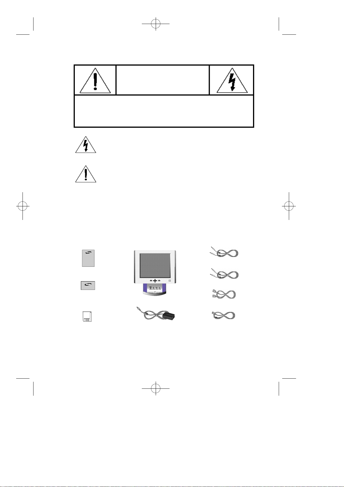
Please make sure the following items are included with your computer monitor:
Microphone Output Cable
This Manual
Sound Cable
Warranty Card
(not available in all areas)
Diskette
Note: You can connect the LCD monitor to a Macintosh computer using an optional
adapter. For the optional adapter, please contact your LCD monitor dealer.
ii
Monitor and Stand-base
DC Adapter (Optional)
Signal Cable
Power Cable
Page 3
320+520-E 7/21/98 11:33 AM Page 1
Precautions . . . . . . . . . . . . . . . . . . . . . . .2
Overview of LCD Monitor . . . . . . . . . . . .3
Installation . . . . . . . . . . . . . . . . . . . . . . . .5
Adjusting Your LCD Monitor . . . . . . . . . .6
Table of Contents
Frontview........................................................................................3
Rearview........................................................................................4
Connecting Your LCD Monitor....................................................5
Screen Image Adjustment...........................................................6
Automatic Adjustment..........................................................7
Manual Adjustments.............................................................8
Non-OSD Controls...............................................................12
Audio Controls......................................................................13
Audio Adjustment................................................................13
Power Saver.................................................................................14
Troubleshooting ..........................................................................15
A p p e n d i x . . . . . . . . . . . . . . . . . . . . . . . . .1 8
Electrical Specifications............................................................18
Mechanical Specifications.......................................................19
Pin Assignments.........................................................................20
Display Modes Timing Chart.....................................................21
1
Page 4
320+520-E 7/21/98 11:33 AM Page 2
P
recautions
Please read and follow these instructions when connecting and using your LCD monitor.
Do not touch the surface of the LCD monitor panel with objects having sharp tips or edges.
Although the surface of the TFT-LCD monitor has been coated to have scratch resistance,
touching the surface with sharp objects can damage the panel.
Do not press hard or allow heavy objects to fall onto the sur face of the LCD monitor.
Keep the LCD monitor away from direct sunlight and other heat sources.
Setting up the LCD monitor under direct sunlight can significantly decrease the contrast and
increase glare. Also, if the ambient temperature is out of the guaranteed operation specification, the panel can show residual images that will overlap other images.
This ghost-like residual image will gradually disappear as time passes, but for some
extreme cases this residual image means that the LCD panel has been permanently damaged.
When you set up the LCD monitor, allow enough room for ventilation around the back of the
LCD monitor cabinet.
The LCD monitor has guaranteed operation temperature specifications.
Reserving ample space for ventilation and not blocking the ventilation holes on the back of
the monitor is essential for the safe and stable operation of the LCD monitor.
Use the enclosed power cord and optional adapter.
The enclosed power cord and optional adapter are specifically designed for the LCD monitor
you just purchased. Connecting a different power cord and adapter can cause a fire or
equipment damage.
Keep liquids away fr om the LCD monitor.
Although the LCD panel is especially coated to protect it from scratches, dust and moisture,
it is not waterproof. Spillage onto the LCD panel or cabinet can result in electric shock
and/or permanent equipment damage. When you spill liquid on the cabinet, unplug the LCD
monitor immediately and have it checked by a qualified technician.
Do not use any strong solvents or abrasive cleansers to clean the LCD panel.
The use of any strong solvents or abrasive cleansers can damage the very thin coating
layer. This coating improves the screen quality of the LCD monitor.
Use a soft cloth to protect the surface of the LCD monitor when removing dust or any stains.
2
Page 5
320+520-E 7/21/98 11:34 AM Page 3
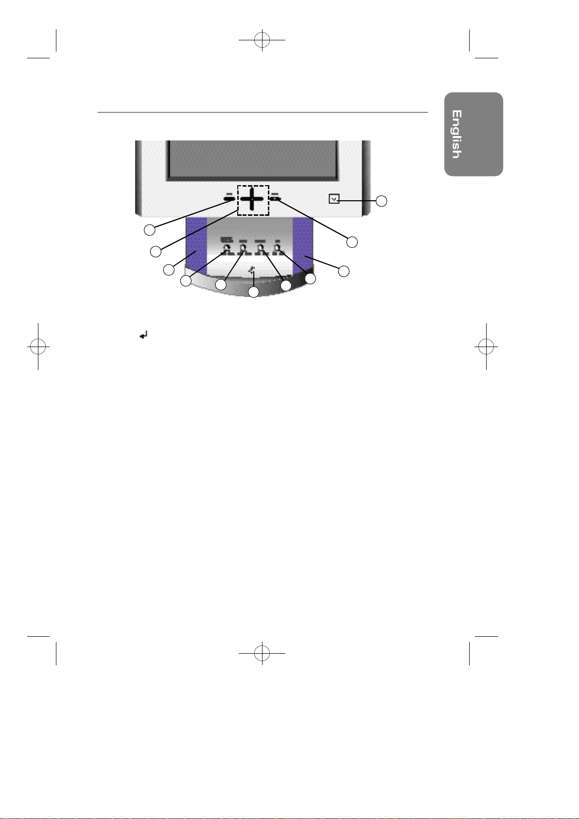
Frontview
2
3
Overview of LCD Monitor
4
1
10
Screen Controls
5
6
9
8
7
10
1. Menu [ ] button. Use this button to activate the on-screen display or to enter a
selection in the on-screen display.
2. Exit button. Use this button to exit the on-screen display.
3. Up [ ▲ ] / Down [ ▼] and –/+ buttons.
Use these buttons to choose or adjust items in the on-screen display.
4. Power button and Indicator.
Use this button to turn the monitor On and Off. The indicator light in the middle of
the button glows green during normal operation and glows amber while the
monitor is in the power saving mode or if the signal cable is disconnected.
Audio Controls
5. Audio On/Off and Volume.
Use this button to turn the sound On and Off and to control the sound volume.
6. Bass. Use this button to adjust the volume of the low sounds.
7. Treble. Use this button to adjust the volume of the high sounds.
8. Microphone On/Off. Use this button to turn the internal microphone On or Off.
9. Microphone. Picks up sound and sends it to the sound card in your PC.
10. Amplified Stereo Speakes
3
Page 6
320+520-E 7/21/98 11:34 AM Page 4
Overview of LCD Monitor
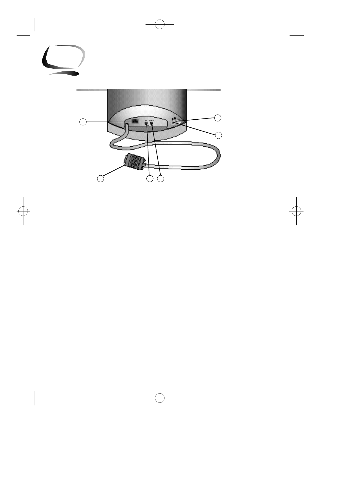
Rearview
2
1
3 4
6
5
1. Signal cable.
Connect your signal cable to the port of video card in the PC.
2. Power port.
Connect the power cable here.
3. Microphone out port.
Connect a cable here to send sound from the monitor’s microphone to the computer’s sound card.
4. Audio in port.
Connect a cable here to bring in sound from your computer’s sound card.
5. External microphone jack.
Connect an external microphone here. Using an external microphone automatically disconnects the monitor’s internal microphone.
6. Headphone jack.
Connect headphones here. When you connect headphones, the monitor’s speakers are turned off.
4
Page 7
320+520-E 7/21/98 11:34 AM Page 5
Before connecting the LCD monitor to your computer, make sure that your computer
supports the video mode supported by the LCD monitor. If the video mode, at the time
of installation, is not one supported by the LCD monitor, the LCD monitor may not display the image as it is intended.
Connecting Your LCD Monitor
1. Be sure that the power switches of both the Computer and the LCD monitor are OFF.
2. If you are using a Macintosh computer, connect the other end of the signal cable
to a Macintosh adapter. (The adapter is not included with your monitor. Contact
your dealer for more information.) If you are using a standard PC and graphics
board, skip to step 5.
3. Follow the instructions included with your Macintosh-to-PC adapter to set the
configurations on your adapter, if necessory.
4. Connect the signal cable to the video port on the back of your computer.
This port might be directly attached to your computer, or it might be part of a video
board, video card, or graphics card.
5. Connect the power cable for the LCD monitor to the back of your monitor.
6. Follow the directions that came with your sound card or your computer to connect
the monitor’s speakers and microphone.
7. Plug the computer and monitor power cables into a nearby outlet.
8. Turn your computer and monitor on.
If your monitor displays an image, you have successfully installed the monitor.
If the monitor does not display an image, check all the connections and follow the
troubleshooting guide beginning on page 15.
9. Your LCD monitor is now ready to use, but to get the best image on the LCD moni
tor, most of the LCD monitor parameters must be fine tuned to work with the video
adapter you are using. The following sections will guide you through the step-bystep procedures for adjusting the parameters for your specific needs.
Your LCD monitor uses an On-Screen Display (OSD) which gives you a convenient way to fine
tune the quality of the screen image. Six control buttons on the front panel of the LCD monitor
are used to operate the OSD menu.
Installation
5
Page 8
320+520-E 7/21/98 11:34 AM Page 6
Adjusting Your LCD Monitor
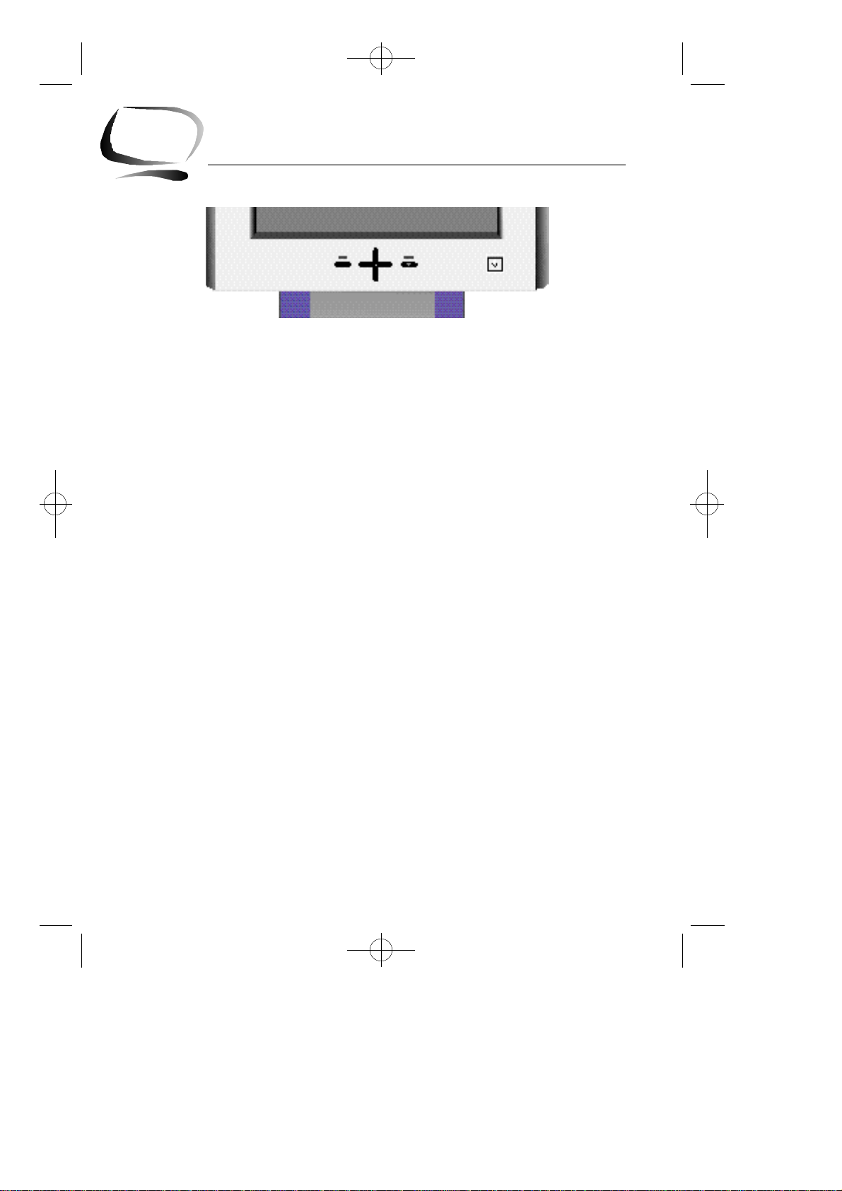
1. The MENU button turns on the menu and activates the highlighted function.
2. Push the EXIT button to stop and close the OSD.
3. Use the ▲ and ▼ buttons to move between the function menus, and use the –and + but-
tons to make adjustments to the selected function option.
Your LCD monitor also provides audio controls located on the front of the stand. The audio
controls are described starting on page 13.
Screen Image Adjustment
Tip 1:
The LCD monitor needs time to become thermally stable the first time you turn it on each day.
Thus, to achieve more accurate adjustments for parameters, allow the LCD monitor to warm
up (be On) for at least 20 minutes before making any screen adjustments.
Tip 2:
The image on the LCD monitor is viewed best when the monitor is placed just below eye level.
Please tilt the monitor screen for your viewing comfort.
Tip 3:
The accompanying installation diskette with the label “Screen Manager” contains utilities that
are useful when making screen adjustments. Install and run the Screen Manager and read
the “readme.txt” file before you make adjustments.
Caution: Do not push and hold in for more than 3 seconds any control button on the front
panel of the monitor. Doing so may activate a special function that replaces the
parameters with the factory preset values.
6
Page 9
320+520-E 7/21/98 11:34 AM Page 7
Adjusting Your LCD Monitor
Automatic Adjustment
Your LCD monitor is designed to interface with the standard analog Red, Green and Blue video
signals from a PC or graphics video board. The video signal from a PC is converted to a digital
signal through an Analog-to-Digital Converter (ADC). To make the proper conversion for accurate image performance, the LCD monitor must generate exactly the same pixel clock rate and
must synchronize it with the clock signal coming from the PC. When the clocks are not correctly matched, some vertical and horizontal distortion may appear on the screen.
Using the Automatic Adjustment function, you can get a more stable image. Your LCD monitor
can automatically set most adjustment parameters: Video Gain, Frequency, Fine, and Position
using the OSD Auto Adjustment function. Even though you can set most image adjustments
automatically, distortion or noise may remain depending on the video board performance.
Thus, after using the Auto Adjustment function, we recommend that you readjust the function
settings to get the very best picture possible.
Caution: Use only the Samsung provided software and the OSD to make parameter adjust
ments. Software available from other vendors will not work properly with this LCD
monitor and may damage the monitor.
Procedure
1. Turn on your PC in accordance with its instructions and push the Power button on the front
of your LCD monitor.
2. Install the Screen Manager utility program into your PC system in accordance with the
“readme.txt” file.
3. Run the Screen Manager utility program by clicking the icon, and follow the instructions.
4. Use the ▼ button to move down and to highlight the icon and see the Auto/Reset
menu, then push the MENU button again.
5. If Auto Adjustment is not highlighted, use the ▲ button to highlight it and push the MENU
button again.
Quick Step : Push the + button twice to star t the Auto Adjustment Function.
6. Push the + button to activate the Auto Adjustment function.
7. If you notice horizontal or ver tical lines flickering on your scr een, use the Coarse and Fine
functions found on the Image Lock menu to reduce or eliminate these lines.
8. If the display area is not centered on the screen, use the Position menu to move the display
area horizontally and/or vertically on the screen.
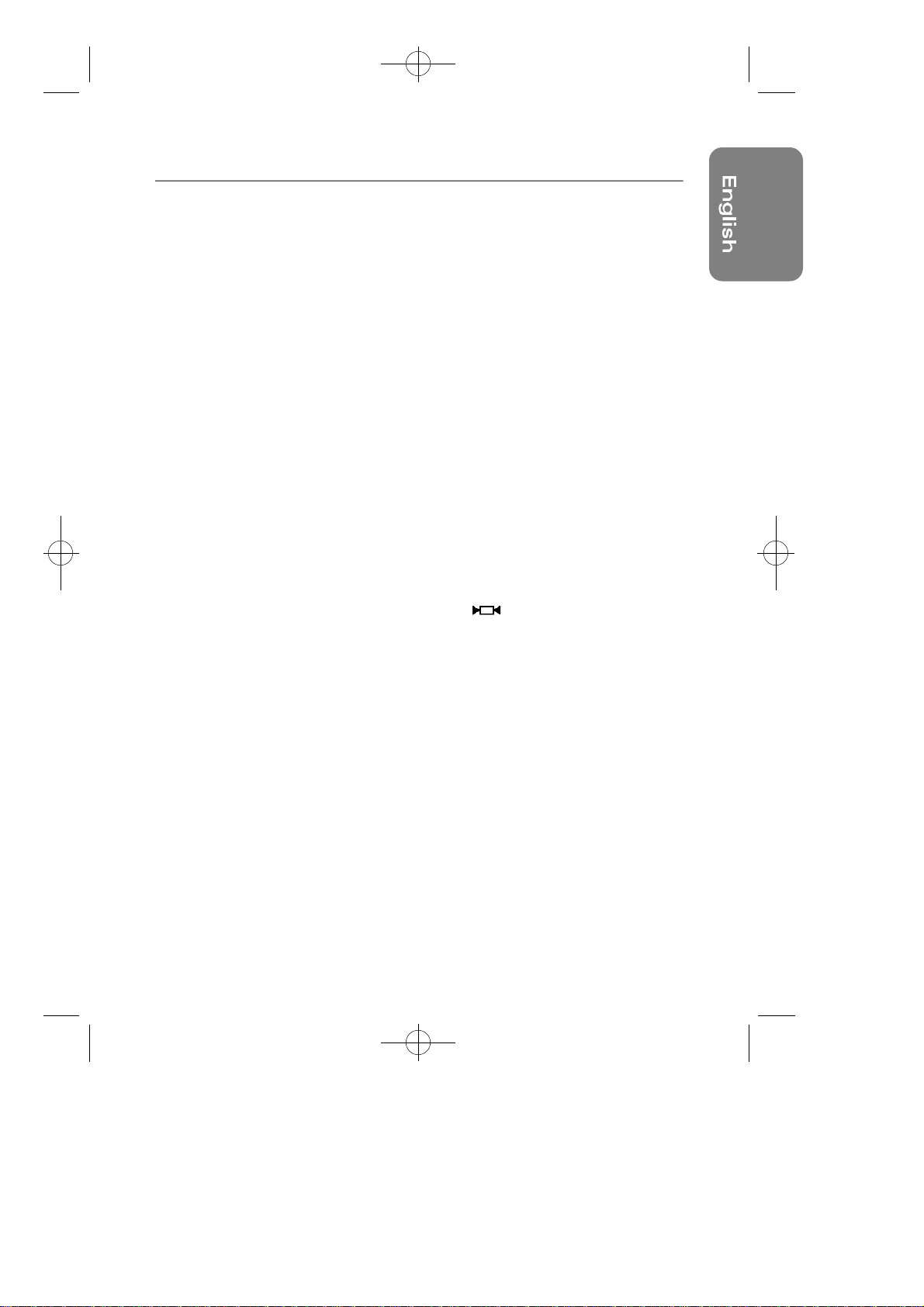
9. Use the Brightness and Contrast menus to adjust the screen for your eye comfort.
10. Make any other desired adjustments using the OSD menus and the directions found in the
following sections.
11. We suggest that you lock the OSD menu system when you have your LCD monitor properly
adjusted.
12. Exit the OSD menu system by pushing the EXIT button 1 or 2 times until the OSD menu disappears.
Caution: After the OSD disappears, do not continue holding in the EXIT button. If you do, the
OSD may reset to the original factory settings and you will need to make your adjust
ments again.
7
Page 10
320+520-E 7/21/98 11:34 AM Page 8
Adjusting Your LCD Monitor
Manual Adjustments
When making adjustments to the way your LCD monitor displays an image, we recommend
that you use the test pattern provided by the SyncMaster Screen Manager. If your computer
operating system cannot run this utility program, display a checkerboard pattern on the
screen. For Macintosh users, you can display a checkerboard pattern using the General
Controls from the Macintosh Control Panel menu.
The information provided below describes the OSD menu options in the order that they appear
on the OSD. When you first install your monitor, we recommend that you first use the
Automatic Adjustment procedure as outlined above before making other adjustments. The
numbers shown along the right side of the Brightness, Contrast, Image Lock, Position, Color
Control and Menu Position OSD windows represent arbitrary values for reference only.
OSD Icon Function
Effect of Button
& Menu Name – +
Brightness
Contrast
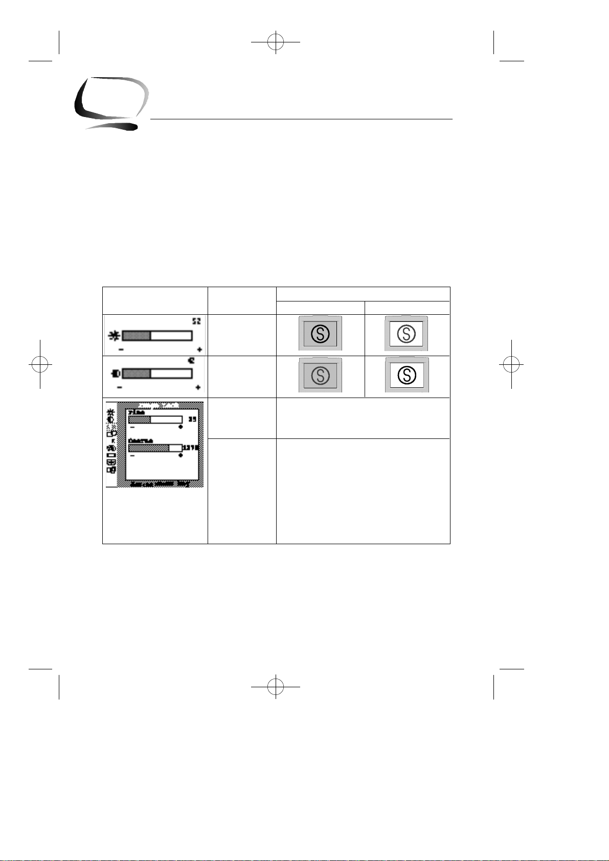
Image Lock
Fine
These functions correct for noise (slight
i n t e rf e rence) in the video signal from the
computer or video board.
Fine eliminates or limits noise which causes
horizontal lines or areas on the scre e n
where the image appears to be unstable and
jitters, shimmers or flickers. Use the – and +
buttons to adjust away the interf e rence. If
you cannot get satisfactory results using the
Fine adjustment, get the best results you can
with the Coarse adjustment then use Fine
again.
8
Page 11
320+520-E 7/21/98 11:34 AM Page 9
Adjusting Your LCD Monitor
OSD Icon Function
Effect of Button
& Menu Name – +
Coarse
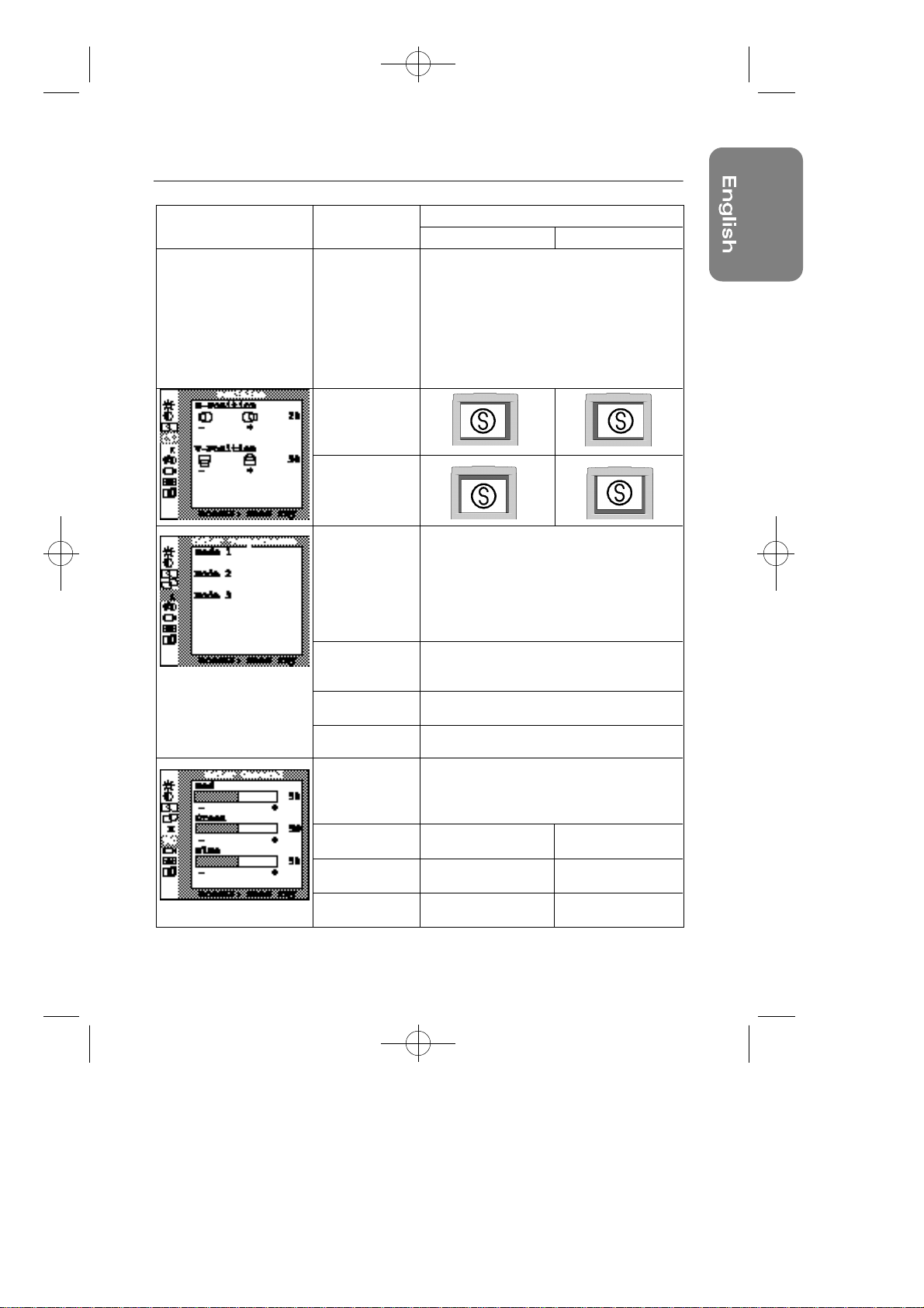
Position
H-Position
V-Position
Color
Temperature
Mode 1
Coarse eliminates or limits noise which
causes vertical lines or areas on the screen
where the image appears to be unstable and
jitters, shimmers or flickers. This function
slightly changes the width of the display
image. Use the H-Position function on the
Position menu to center the display image on
the screen.
Color temperature changes the color coordi-
nates to make the colors appear more warm
(red) or cool (blue) or to use the LCD natural
characteristics. Select the mode you find
most comfortable using then fine tune the
colors using the Color Control menu.
Colors appear with the LCD panel’s natural
characteristics.
Mode 2
Mode 3
Color Control
Red
Green
Blue
Colors appear more cool with a bluish cast
Colors appear more warm with a reddish cast
After selecting a Color Te m p e r a t u re mode,
you can adjust the hue that the screen displays for red, green and blue.
Decrease redness Increase redness
Decrease greenness Increase greenness
Decrease blueness Increase blueness
9
Page 12
320+520-E 7/21/98 11:34 AM Page 10
Adjusting Your LCD Monitor
OSD Icon Function
Effect of Button
& Menu Name – +
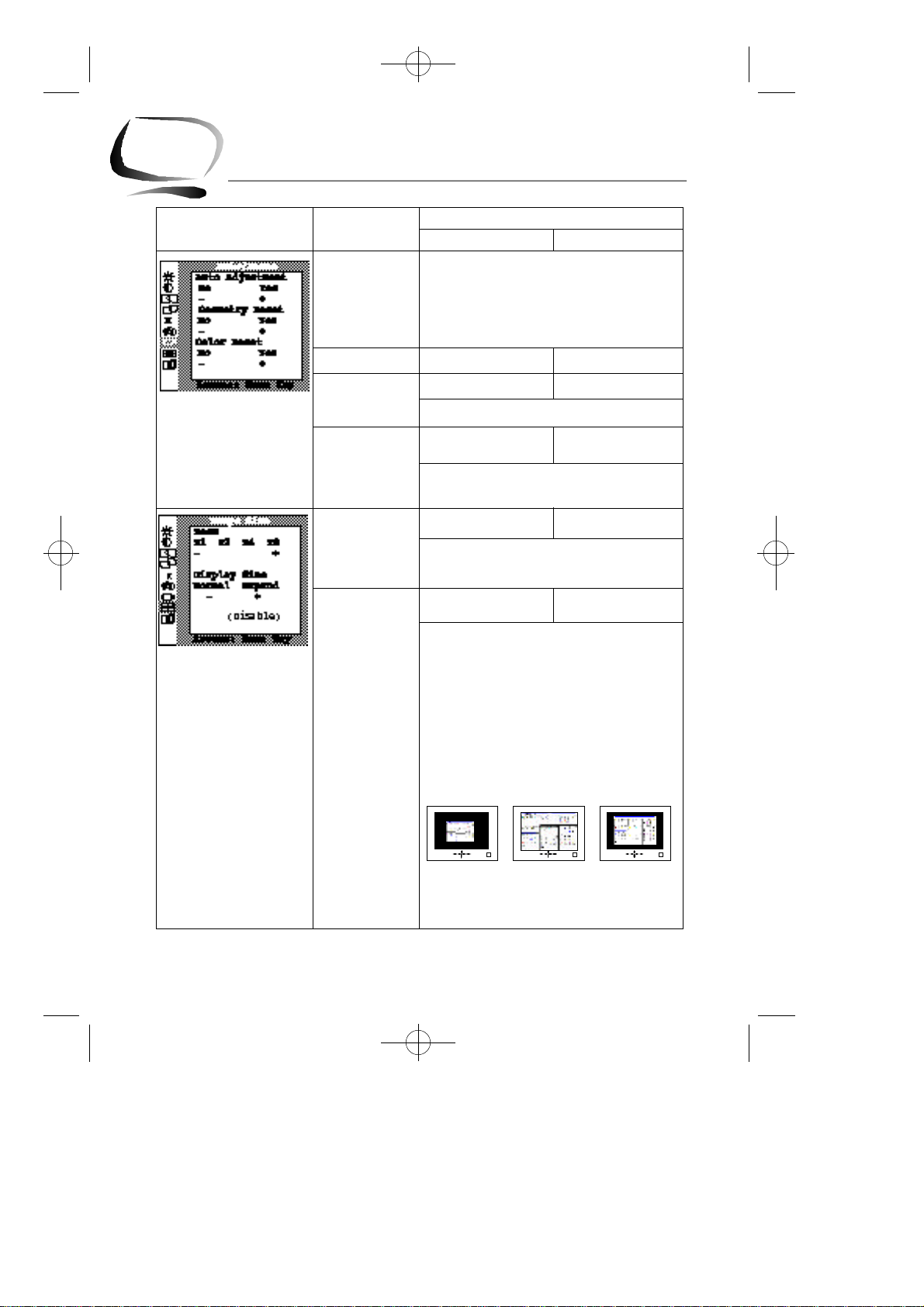
Auto / Reset
Auto Adjustment
Geometry
Reset
Color Reset
Image Size
Zoom
Display Size
See page 7 for a complete description of
the Automatic Adjustment function. Use the
two Reset functions to re s t o re the scre e n
settings to their original manufacturing sett i n g s .
No Yes
No Yes
Resets the Position and Zoom functions.
No Yes
Resets the Brightness, Contrast and Color
Control functions.
Move highlight left Move highlight right
Scales the contents of the entire display are a
to 1, 2, 4, and 8 times the normal size.
Normal Expand
If your computer or video board supplies a
signal rate and resolution lower than
1024x768, this LCD monitor provides a scaling processor which can expand the rate up
to 1024x768. If the signal rate is already XGA
(1024x768) you will see “(Disable)” below
Expand. This means that this function is not
available because the screen is already at
its largest size.
10
Normal
(VGA:640X480)
Expanded
(1024X768)
Normal
(SVGA:800X600)
Page 13
320+520-E 7/21/98 11:34 AM Page 11
Adjusting Your LCD Monitor
OSD Icon Function
Effect of Button
& Menu Name – +
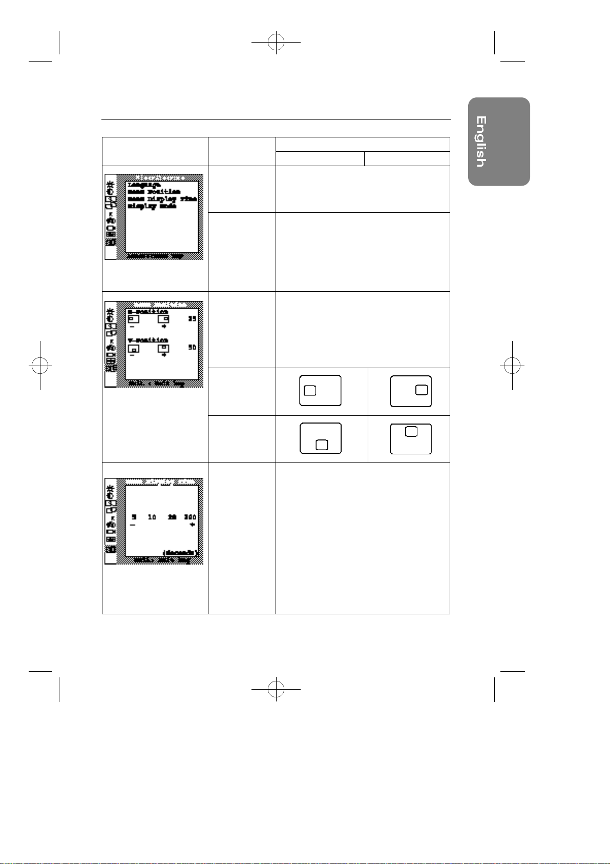
M i s c e l l a n e o u s
Language
English
Deutsch
Español
Français
Italiano
Menu Position
H-Position
V-Position
This menu offers functions that you may find
useful, but will probably use only when
initially setting up your LCD monitor.
Use the ▲ and ▼ buttons to select one of
the five languages to use for the OSD. The
language you choose affects only the language that the OSD displays. It has no effect
on any software running on your computer.
This function allows you to set the location
where the OSD menu displays on your
screen.
The default location is in the center of the
screen.
Menu Display
Time
This function defines how long the OSD will
stay active, after you stop pushing any buttons. Use the – and + buttons to select
between 5, 10, 20, and 200 seconds.
11
Page 14
320+520-E 7/21/98 11:34 AM Page 12
Adjusting Your LCD Monitor
OSD Icon Function
Effect of Button
& Menu Name – +
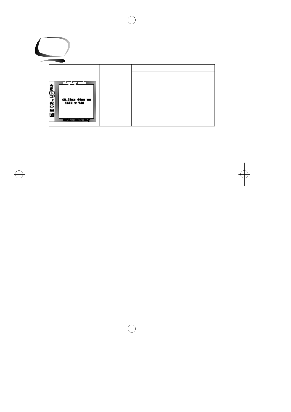
Display Mode
This is an information only screen which
shows the frequency and resolution that your
LCD monitor is receiving from your computer
or video board.
Non-OSD Controls
OSD Locking
You can lock the OSD controls to protect your settings from accidental or unwanted changes
by pushing and holding in the MENU button for 5 seconds.
The OSD will open then close automatically. When you open the OSD again, “Locked” will
appear along the bottom of most menus and you cannot change any controls except
Brightness and Contrast.To unlock the OSD, push and hold in the MENUbutton for 5 seconds
again.
12
Page 15
320+520-E 7/21/98 11:34 AM Page 13
Adjusting Your LCD Monitor
Audio Controls
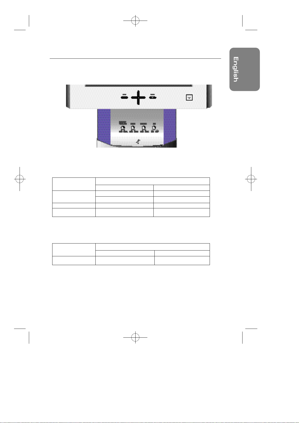
Your LCD monitor provides four audio control buttons located on the front of the stand.
Audio Adjustments
To access the On/Off, Volume, Bass and Treble functions, push the appropriate blue control
button until it pops out, then turn it to the right or left to adjust the function.
Function Name
Audio On/Off and Off On
Volume Decrease volume Increase volume
Bass Decrease low sounds Increase low sounds
Treble Decrease high sounds Increase high sounds
Your LCD monitor includes an internal microphone which you can turn On or Off using the
rightmost control of the Audio controls.
Function Name
Microphone On/Off On Off
Left Right
Effect of Control Movement
Effect of Control Movement
In Out
13
Page 16
320+520-E 7/21/98 11:34 AM Page 14
Adjusting Your LCD Monitor
Power Saver
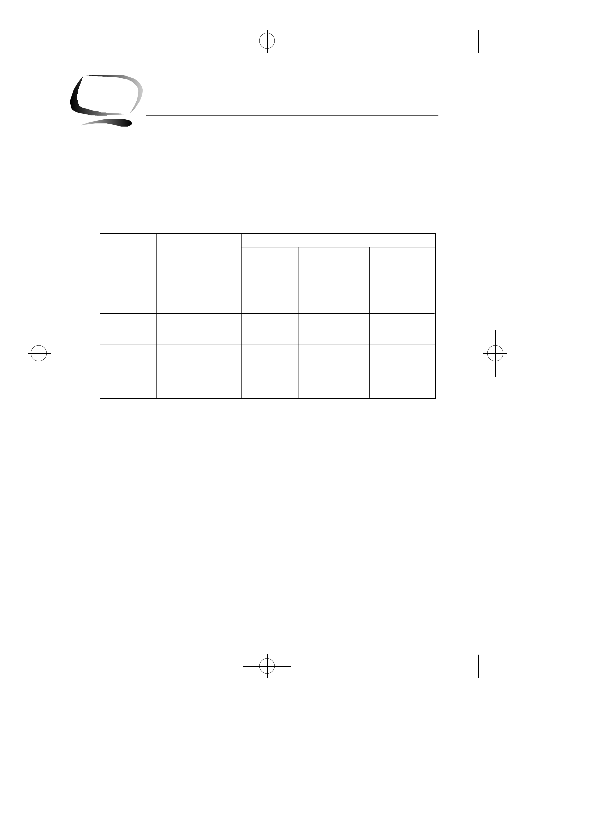
This monitor has a built-in power management system called PowerSaver. This system saves
energy by switching your monitor into an off mode when it has not been used for a certain
amount of time.
This system operates with a VESA DPMS compliant video card installed in your computer. You
use a software utility installed on your computer to set up this feature. See the table below for
details.
State Normal
operation
Horizontal Sync
Vertical Sync
Video
Active
Active
Active
Power-Saving Function Mode EPA/NUTEK
Standby Suspend mode/ Power-off mode/
mode Position A1
Inactive
Active
Blanked
Active Inactive
Inactive Inactive
Blanked Blanked
Position A2
Power Indicator
Power
Consumption
Green
320TFT : 40W(max.)
30W(nominal)
520TFT : 45W(max.)
35W(nominal)
Amber
Less than 5 W
Amber Blinking Amber Blinking
(0.5 Sec,Interval) (1.0 Sec,Interval)
Less than 5 W Less than 5 W
NOTE: This monitor automatically returns to normal operation when horizontal and vertical
sync return. This occurs when you move the computer's mouse or press a key on the
keyboard.
This monitor is EPAEnergy Star compliant and NUTEK compliant when used with a computer
equipped with VESA DPMS functionality. If your computer system cannot support a display
power management function, you can purchase an optional DPMS software program to
enable the power saving function. Please contact Samsung or your dealer for more information.
For energy conservation, turn your monitor OFF when it is not needed, or when leaving it
unattended for long periods.
14
Page 17
320+520-E 7/21/98 11:34 AM Page 15
Adjusting Your LCD Monitor
Troubleshooting
If you have a problem setting up or using your LCD monitor, you may be able to solve it yourself. Before contacting customer service, try the suggested actions that are appropriate to
your problem.
Image Problems
Problem Suggested Action Reference
Screen is blank and power
indicator is off.
• Ensure that the power cord
Installation, page 5
is firmly connected and the
LCD monitor is On.
“Check Signal Cable”
appears on screen.
The image is too light or too
dark
Horizontal bars appear to
flicker, jitter or shimmer on
the image.
Vertical bars appear to flicker,
jitter or shimmer on the
image.
Image is not stable and may
appear to vibrate.
• Ensure that the signal
cable is firmly connected to
the PC or video board.
• Ensure that the PC is
turned On.
• Adjust the Brightness and
Contrast.
• Adjust the Fine function.
• Adjust the Coarse function
and then adjust the Fine
function.
• Check that the display resolution and frequency from
your PC or video board is
an available mode for your
LCD monitor.
• If the setting is not correct,
use your computer utility
program to change the display settings.
Note: Your LCD monitor supports the multiscan display func
tion within the following frequency domain:
Horizontal frequency:
Vertical frequency:
Maximum refresh rate:
Installation, page 5
Brightness, page 8
Contrast, page 8
Image Lock, Fine, page 8
Image Lock, Coarse, page 9
Image Lock, Fine, page 8
Misc., Display Mode, page 12
Display Modes Timing Chart,
page 21
On your computer: Display
Settings.
For Windows 95 or later, use
“Start”, “Settings”, “Control
Panel”, “Display”, and
“Settings”.
30 kHz - 61 kHz
50 Hz - 75 Hz
1024 x 768 @ 75 Hz
15
Page 18
320+520-E 7/21/98 11:34 AM Page 16
Adjusting Your LCD Monitor
Problem Suggested Action Reference
Image is too small using the
VGA and SVGA resolution.
• Use the Expand function to
Image Size, Expand, page 10
stretch the image to
1024x768.
Image is too big and extends
beyond the edge of the
screen.
Image is not centered on the
screen.
Audio Problems
Problem Suggested Action Reference
No sound.
Sound level is too low.
• Disable or adjust the
Zoom-in function as appropriate.
• Adjust the image horizontal
and vertical position.
• Ensure that the audio cable
is firmly connected to both
the audio-in port on your
LCD monitor and to the
audio-out port on your
sound card or computer.
• Rotate the Audio On/Off
and Volume control to the
right to turn it on and raise
the volume.
• Rotate the Audio On/Off
and Volume control to the
right to raise the volume.
• If the volume is still too low
after turning the control to
its maximum, check the
volume control on the computer sound card or software program.
Image Size, Zoom, page 10
Position, H-Position, page 9
Position, V-Position, page 9
Installation, page 5
Audio Controls, page 13
Audio Controls, page 13
Refer to your computer,
sound card or software documentation.
16
Page 19
320+520-E 7/21/98 11:34 AM Page 17
Adjusting Your LCD Monitor
Problem Suggested Action Reference
Howling effect occurs.
• Decrease the volume
• If you are using an external
Audio Controls, page 13
slightly.
microphone, move it away
from the speakers and
adjust the volume level.
Sound is too high pitched or
too low pitched.
Microphone is not working.
• Adjust the Treble and Bass
as appropriate.
• Check the microphone
cable connection.
• Your sound card must be
compatible with an internal, embedded microphone. If it is not, use the
microphone that came with
your computer or sound
card.
Audio Controls, page 13
Installation, page 5
Your computer or sound card
documentation.
17
Page 20
320+520-E 7/21/98 11:34 AM Page 18
Appendix
Electrical Specifications
LCD Panel Size: 13.3” diagonal 15.0” diagonal
Display area: 270.3 (H) x 207.8 (V) 304.1 (H) x 228.1 (V)
Type: Amorphous silicon TFT LCD (Liquid Crystal Display)
Pixel pitch: 0.264 (H) x 0.264 (V) 0.297 (H) x 0.297 (V)
Viewing angle: 55/55/60/60 (U/D/L/R) (degrees)
Synchronization (Scan Frequency)
Horizontal: 30 -61kHz (Automatic scanning)
Vertical: 50-75Hz(Automatic scanning)
Display Colors: 16.7 Million colors
Display Resolution
Optimum mode: 1024 dots x 768 lines
Native mode: 640 x 480, 800 x 600, 832 x 624 (Macintosh), 1024 x 768
Expand mode: 640 x 480 -> 1024 x 768
SyncMaster 320TFT SyncMaster 520TFT
(1024x768 is upto 75Hz)
800 x 600 -> 1024 x 768
832 x 624 -> 1024 x 768 (Macintosh)
1024 x768-> 1024 x 768
Maximum Input Pixel Clock: 80MHz at 1024x768@75Hz
Input Signal
Sync: H/V Separate, TTL, Positive or Negative
H/V Composite, TTL, Positive or Negative
Sync-On-Green 0.3 Vp-p, Negative
Video signal: 0.714Vp-p@75 ohm, Positive
Signal Cable: 26 pin MDR connector (monitor) to 15 pin d-sub (PC)
Power Supply: AC 100-240 Volt ± 10%, 60Hz/50Hz ± 3Hz
Power Consumption
Normal: 30 Watt (without audio) 35 Watt (without audio)
Maximum: 40 Watt (with audio) 45 Watt (with audio)
Power Saving: 5 Watt 5 Watt
(VESA DPMS compliance) (VESA DPMS compliance)
18
Page 21
320+520-E 7/21/98 11:34 AM Page 19
Mechanical Specifications
Dimension
Unit (WxHxD): 355.0 x 395.0 x 196.0 mm 404.0 x 419.0 x 196.0mm
Carton (WxHxD): 455.0 x 488.0 x 282.0 mm 475.0 x 510.0 x 282.0 mm
Weight
Unit: 6.4Kg 7.5Kg
Carton: 8.0Kg 9.5Kg
Environmental Considerations
Operating Temperature: 50˚ F to 104˚ F (10˚ C to 40˚ C)
Operating Humidity: 10% to 80%
Storage Temperature: -13˚ F to 113˚ F (-25˚ C to 45˚ C)
Storage Humidity: 5% to 95%
Appendix
SyncMaster 320TFT SyncMaster 520TFT
Audio Characteristics
Built-in Microphone: High Sensitivity Condenser Microphone (mono)
Sound Output: 1.0W (left) + 1.0W (right)/THD 1% at 4ohm
Frequency Response: 80Hz - 20KHz (at -3dB)
Audio Input: Left/Right Stereo Phone Jack, 0.5Vrms
Headphone: Max 50mW output (3.5-pi jack)
19
Page 22
320+520-E 7/21/98 11:34 AM Page 20
Appendix
Pin Assignments
1. 15pin-26pin D-sub connector (slim-type), 15-pin side
Pin Separate H/V Composite H/V Sync-on-green
1 Red Red Red
2 Green Green Green + H/V Sync
3 Blue Blue Blue
4 GND GND GND
5 GND (DDC Return) GND (DDC Return) GND (DDC Return)
6 GND-Red GND-Red GND-Red
7 GND-Green GND-Green GND-Green
8 GND-Blue GND-Blue GND-Blue
9 No Connection No Connection Not used
10 GND-Sync/Self Test GND-Sync/Self Test GND-Sync/Self Test
11 GND GND GND
12 DDC Data DDC Data DDC Data
13 Horizontal Sync H/V Sync Not used
14 Vertical Sync Not used Not used
15 DDC Clock DDC Clock DDC Clock
2. 15pin-26pin D-sub connector (slim-type), 26-pin side
Pin Separate H/V Composite H/V Sync-on-green
1 Red Red Red
2 Green Green Green + H/V Sync
3 Blue Blue Blue
4 GND GND GND
5 GND (DDC Return) GND (DDC Return) GND (DDC Return)
6 GND-Red GND-Red GND-Red
7 GND-Green GND-Green GND-Green
8 GND-Blue GND-Blue GND-Blue
9 No Connection No Connection Not used
10 GND-Sync/Self Test GND-Sync/Self Test GND-Sync/Self Test
11 GND GND GND
12 DDC Data DDC Data DDC Data
13 Horizontal Sync H/V Sync Not used
14 Vertical Sync Not used Not used
15 DDC Clock DDC Clock DDC Clock
16~
26
20
GND GND GND
Page 23
320+520-E 7/21/98 11:34 AM Page 21
Display Modes Timing Chart (Factory preset Modes)
No. Display mode Horizontal Vertical Pixel Clock Sync Polarity
Frequency Frequency (horiz./vert.)
1 VGA, 640x350 31.47kHz 70.00Hz 25.175MHz +/2 VGA, 720x400 31.47kHz 70.00Hz 28.322MHz -/+
3 VGA, 640x480 31.47kHz 60.00Hz 25.175MHz +,-/+,4 VGA, 640x480 37.50kHz 75.00Hz 31.500MHz +,-/+,5 Mac, 640x480 35.00kHz 66.667Hz 30.240MHz -/6 SVGA, 800x600 35.16kHz 56.20Hz 36.000MHz +,-/+,7 SVGA, 800x600 37.88kHz 60.30Hz 40.000MHz +,-/+,8 SVGA, 800x600 46.87kHz 75.00Hz 49.500MHz +,-/+,9 Mac, 832x624 49.73kHz 75.00Hz 57.250MHz +,-/+,-
10 XGA, 1024x768 48.36kHz 60.00Hz 65.000MHz +,-/+,11 XGA, 1024x768 56.48kHz 70.00Hz 75.000MHz +,-/+,12 XGA, 1024x768 60.02kHz 75.00Hz 78.750MHz +,-/+,-
Appendix
21
Page 24
320+520-E 7/21/98 11:34 AM Page 22
FCC Information
User Instructions
The Federal Communications Commission Radio
Frequency Interference Statement includes the following
warning:
NOTE: This equipment has been tested and found to comply
with the limits for a Class B digital device, pursuant to Part 15
of the FCCRules. These limits are designed to provide re a s o nable protection against harmful interf e rence in a re s i d e n t i a l
installation. This equipment generates, uses, and can radiate
radio frequency energy and, if not installed and used in accordance with the instructions, may cause harmful interf e re n c e
to radio communications. However, there is no guarantee that
i n t e rf e rence will not occur in a particular installation.
If this equipment does cause harmful interf e rence to radio or
television receptions, which can be determined by turning the
equipment off and on, the user is encouraged to try to corre c t
the interf e rence by one or more of the following measure s :
• Reorient or relocate the receiving antenna.
• Increase the separation between the equipment and
receiver.
• Connect the equipment into an outlet on a circuit different from that to which the receiver is connected.
• Consult the dealer or an experienced radio/TV technician for help.
User Information
Changes or modifications not expressly approved by the
p a rty responsible for compliance could void the user’s
authority to operate the equipment.
If necessary, consult your dealer or an experienced
radio/television technician for additional suggestions. Yo u
may find the booklet called How to Identify and Resolve
Radio/TV Interf e rence Pro b l e m s helpful. This booklet was
p re p a red by the Federal Communications Commission. It
is available from the U.S. Government Printing Off i c e ,
Washington, DC 20402, Stock Number 004-000-00345-4.
Warning
User must use shielded signal interface cables to maintain FCC compliance for the product.
Declaration of conformity for products Marked with FCC Logo
This device complies with Part 15 of the FCC Rules.
Operation is subject to the following two conditions: (1)
this device may not cause harmful interf e rence, and (2)
this device must accept any interf e rence received, including interference that may cause undesired operation.
The party responsible for product compliance:
SAMSUNG ELECTRONICS CO., LTD
QA Lab of Samsung America
85 West Tasman Drive
San Jose, CA 95134 USA
Tel) 408-544-5124
Fax) 408-544-5191
Provided with this monitor is a detachable power supply
cord with IEC320 style terminations. It may be suitable for
connection to any UL Listed personal computer with similar configuration. Before making the connection, make
sure the voltage rating of the computer convenience outlet is the same as the monitor and that the ampere rating
of the computer convenience outlet is equal to or
exceeds the monitor voltage rating.
For 120 Volt applications, use only ULListed detachable
power cord with NEMA configuration 5-15P type (parallel
blades) plug cap. For 240 Volt applications use only UL
Listed Detachable power supply cord with NEMA configuration 6015P type (tandem blades) plug cap.
IC Compliance Notice
This Class B digital apparatus meets all requirements of
the Canadian Interference-Causing Equipment
Regulations of ICES-003.
Cet appareil numérique de classe B respecte toutes les
exigences du Règlement ICES-003 sur les équipements
produisant des interférences au Canada.
MPR II Compliance
This monitor complies with SWEDAC (MPR II) re c o m m e n d ations for reduced electric and magnetic fields.
European Notice
Products with the CE Marking comply with both the EMC
Directive (89/336/EEC), (92/31/EEC), (93/68/EEC) and the
Low Voltage Directive (73/23/EEC) issued by the
Commission of the European Community.
Compliance with these directives implies conformity to
the following European Norms:
• EN55022 (CISPR 22) – Radio Frequency Interference
• EN50082-1 : 1992 – Electromagnetic Immunity
• EN60555-2 (IEC555-2) – Power Line Harmonics
• EN60555-3 (IEC555-3) – Voltage Fluctuations
• EN60950 (IEC950) – Product Safety.
Page 25
320+520-E 7/21/98 11:34 AM Page 23
U.S.A. :
Samsung Electronics America (SEA)
One Samsung Place
Ledgewood, NJ 07852
Tel. : 1-800-SAMSUNG (1-800-726-7864)
Fax-on-Demand for product information :
1-800-229-2239
CANADA :
Samsung Electronics Canada Inc.
7037 Financial Drive
Mississauga, Ontario L5N 6R3
Tel. : 1-800-SAMSUNG (1-800-726-7864)
Fax. : (905) 542-1199
GERMANY :
Samsung Electronics GmbH Samsung-Haus
Am Kronberger Hang 6/65824 Schwalbach/Ts.
Tel. : 06196-66-1134
Fax. : 06196-66-1133
AUSTRALIA :
Samsung Electronics Australia Pty Ltd.
Unit G, 10-16 South Street,
Rydalmere, N.S.W. 2116
P.O. BOX 368
Tel. : (02) 638 5200
ITALIA :
Samsung Electronics Italia SpA
Via C. Donat Cattin,
5-20063 Cernusco sul Naviglio (Mi)
Tel. : 167-010740
PANAMA :
Servicios Samsung (Zona Libre), S.A.
50 and 61 Streets Sta, Cecilia
Bdl. Don Camilo, Panama City
Tel. : (507) 264-0195 or 269-5571
Fax : (507) 269-5568
ESPAÑA :
Samsung Electrónics Comercial Ibérica, S.A.
Ciencies, 55-65 (Polígono Pedrosa) 08908
Hospitalet de Llobregat (Barcelona)
Tel. : (93) 261 67 00
Fax. : (93) 261 67 50
UK :
Samsung Electronics (UK) Ltd.
Samsung House, 225 Hook Rise South
Surbiton, Surrey KT6 7LD
Tel. : (0181) 391 0168
Fax. : (0181) 397 9949
<European Service Center & National Service>
Stafford Park 12 Telford, Shropshire, TF3 3BJ
Tel. : (01952) 292 262
Fax. : (01952) 292 033
THAILAND :
Samsung Service Center
729-729/1 JSP Tower Rachadapisek RD.,
Bangpongpang, Yannawa, Bangkok 10120
Tel : (662) 2954508-14
Fax : (662) 2954267
SOUTH AFRICA :
Samsung Electronics South Africa
Somerset Office Park 5 Libertas Road
Bryanston, South Africa
Tel : (27)-11-463-5678
Fax : (27)-11-463-5215
BRASIL :
Samsung Eletrônica da Amazonia Ltda.
R. Prof. Manoelito de Ornellas, 303-2ºAndar
Chácara Sto. Antônio • cep : 04719-040
São Paulo • SP
Tel. : (011) 541-8500
Fax : (011) 523-3995, 522-0726
CODE NO. : BN68-60002A ( Rev. 0.3 )
Printed on recyclable paper
 Loading...