

Samsung lw22a13w service manual
TFT-LCD TV/MONITOR
Chassis Model
PD22EO LW22A13W
Manual
SERVICE
TFT-LCD TV/MONITOR CONTENTS
1. Precautions
2. Product Specifications
3. Disassembly & Reassembly
4. Alignment & Adjustments
5. Troubleshooting
6. Exploded View & Parts List
7. Electrical Parts List
8. Block Diagram
9. Wiring Diagram
10. Schematic Diagrams
11. Panel Description
CONFIDENTIAL
If you need more information on Computer and Electronic Repair, please visit these
in fact
websites to improve yourself.
http://www.fastrepairguide.com
http://www.protech2u.com
http://www.plasma-television-repair.com
http://www.lcd-television-repair.com
Happy Repairing!!
Highly Recommended Repair Ebook:
If you’re a LCD Monitor repairer, then this is the best guide for you.
Why? Because, the author revealed all his LCD Monitor Repairing
secrets for you. I think, with just few Repair tips you learned from
this guide you will get back your investment!
Click Here to read more.
This eBook will show you how to test the electronic component
correctly and accurately. Some of you may say that I don’t
need this eBook because it is too simple! Do you know that,
there is lots of testing electronic components secrets I have learned
from this guide? Do you know how to test a‘TRIAC’ correctly and
accurately? If you answer no then I guess you have to get this
EBook. Click Here to read more.
Are you tired of searching the service manuals to look for the value
of a burnt resistor? If the answer is YES, then this eBook is a ‘must
have’ guide for you. You can save a lot of time and be able to repair
customer’s Electronic equipment with burnt resistors in it.
Click here to read more.
1-1-1 Warnings
1. For continued safety, do not attempt to modify the
circuit board.
2. Disconnect the AC power and DC Power Jack
before servicing.
1-1-2 Servicing the LCD Monitor
1. When servicing the LCD TV disconnect the AC line
cord from the AC outlet.
2. It is essential that service technicians have an
accurate voltage meter available at all times. Check
the calibration of this meter periodically.
1-1-3 Fire and Shock Hazard
Before returning the monitor to the user, perform the
following safety checks:
1. Inspect each lead dress to make certain that the
leads are not pinched or that hardware is not
lodged between the chassis and other metal parts in
the monitor.
2. Inspect all protective devices such as nonmetallic
control knobs, insulating materials, cabinet backs,
adjustment and compartment covers or shields,
isolation resistor-capacitor networks, mechanical
insulators, etc.
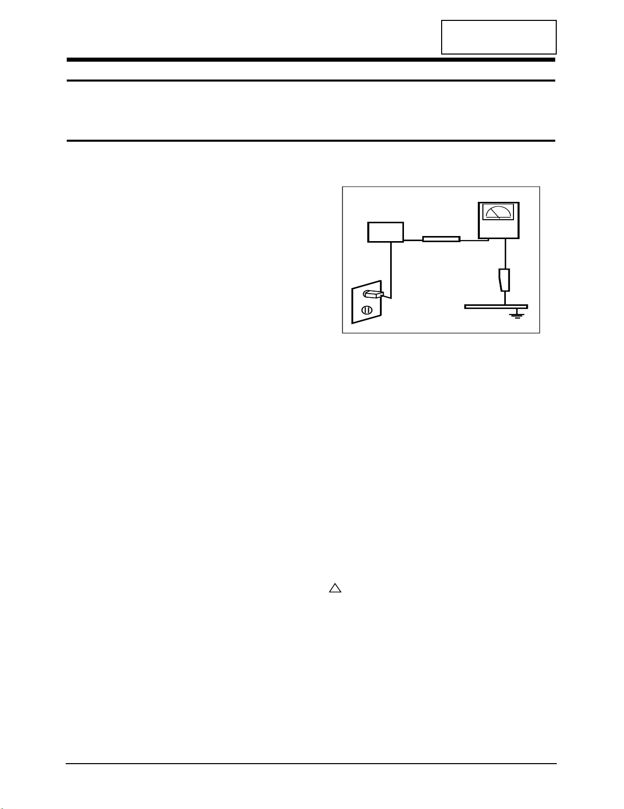
3. Leakage Current Hot Check (Figure 1-1):
WARNING: Do not use an isolation transformer during
this test.
Use a leakage current tester or a metering system
that complies with American National Standards
Institute (ANSI C101.1, Leakage Current for
Appliances), and Underwriters Laboratories (UL
Publication UL1410, 59.7).
Figure 1-1. Leakage Current Test Circuit
4. With the unit completely reassembled, plug the AC
line cord directly into a 120V AC outlet. With the
unit’s AC switch first in the ON position and then
OFF, measure the current between a known earth
ground (metal water pipe, conduit, etc.) and all
exposed metal parts, including: metal cabinets,
screwheads and control shafts. The current
measured should not exceed 0.5 milliamp. Reverse
the power-plug prongs in the AC outlet and repeat
the test.
1-1-4 Product Safety Notices
Some electrical and mechanical parts have special
safety-related characteristics which are often not
evident from visual inspection. The protection they give
may not be obtained by replacing them with
components rated for higher voltage, wattage, etc. Parts
that have special safety characteristics are identified by
on schematics and parts lists. A substitute
replacement that does not have the same safety
characteristics as the recommended replacement part
might create shock, fire and/or other hazards. Product
safety is under review continuously and new
instructions are issued whenever appropriate.
LW22A13W 1-1
CONFIDENTIAL
1 Precautions
Follow these safety, servicing and ESD precautions to prevent damage and to protect against potential hazards such as
electrical shock.
1-1 Safety Precautions
DEVICE
UNDER
TEST
TEST ALL
EXPOSED METAL
SURFACES
(READING SHOULD
NOT BE ABOVE 0.5mA)
LEAKAGE
CURRENT
TESTER
2-WIRE CORD
ALSO TEST WITH
PLUG REVERSED
(USING AC ADAPTER
PLUG AS REQUIRED)
EARTH
GROUND
!
1-2-1 General Servicing Precautions
1. Always unplug the unit’s AC power cord from the
AC power source and disconnect the DC Power
Jack before attempting to:
(a) remove or reinstall any component or assembly,
(b) disconnect PCB plugs or connectors, (c) connect
a test component in parallel with an electrolytic
capacitor.
2. Some components are raised above the printed
circuit board for safety. An insulation tube or tape
is sometimes used. The internal wiring is
sometimes clamped to prevent contact with
thermally hot components. Reinstall all such
elements to their original position.
3. After servicing, always check that the screws,
components and wiring have been correctly
reinstalled. Make sure that the area around the
serviced part has not been damaged.
1. Immediately before handling any semiconductor
components or assemblies, drain the electrostatic
charge from your body by touching a known earth
ground. Alternatively, wear a discharging wriststrap device. To avoid a shock hazard, be sure to
remove the wrist strap before applying power to
the monitor.
2. After removing an ESD-equipped assembly, place it
on a conductive surface such as aluminum foil to
prevent accumulation of an electrostatic charge.
3. Do not use freon-propelled chemicals. These can
generate electrical charges sufficient to damage
ESDs.
4. Use only a grounded-tip soldering iron to solder or
desolder ESDs.
5. Use only an anti-static solder removal device. Some
solder removal devices not classified as “anti-static”
can generate electrical charges sufficient to damage
ESDs.
4. Check the insulation between the blades of the AC
plug and accessible conductive parts (examples:
metal panels, input terminals and earphone jacks).
5. Insulation Checking Procedure: Disconnect the
power cord from the AC source and turn the power
switch ON. Connect an insulation resistance meter
(500 V) to the blades of the AC plug.
The insulation resistance between each blade of the
AC plug and accessible conductive parts (see
above) should be greater than 1 megohm.
6. Always connect a test instrument’s ground lead to
the instrument chassis ground before connecting
the positive lead; always remove the instrument’s
ground lead last.
6. Do not remove a replacement ESD from its
protective package until you are ready to install it.
Most replacement ESDs are packaged with leads
that are electrically shorted together by conductive
foam, aluminum foil or other conductive materials.
7. Immediately before removing the protective
material from the leads of a replacement ESD,
touch the protective material to the chassis or
circuit assembly into which the device will be
installed.
Caution: Be sure no power is applied to the
chassis or circuit and observe all
other safety precautions.
8. Minimize body motions when handling
unpackaged replacement ESDs. Motions such as
brushing clothes together, or lifting your foot from
a carpeted floor can generate enough static
electricity to damage an ESD.
1 Precautions
1-2 LW22A13W
CONFIDENTIAL
1-3 Electrostatically Sensitive Devices (ESD) Precautions
Some semiconductor (solid state) devices can be easily damaged by static electricity. Such components are commonly
called Electrostatically Sensitive Devices (ESD). Examples of typical ESD are integrated circuits and some field-effect
transistors. The following techniques will reduce the incidence of component damage caused by static electricity.
1-2 Servicing Precautions
WARNING: An electrolytic capacitor installed with the wrong polarity might explode.
Caution: Before servicing units covered by this service manual, read and follow the Safety Precautions
section of this manual.
Note: If unforeseen circumstances create conflict between the following servicing precautions and any of the
safety precautions, always follow the safety precautions.
CONFIDENTIAL
2 Product Specifications
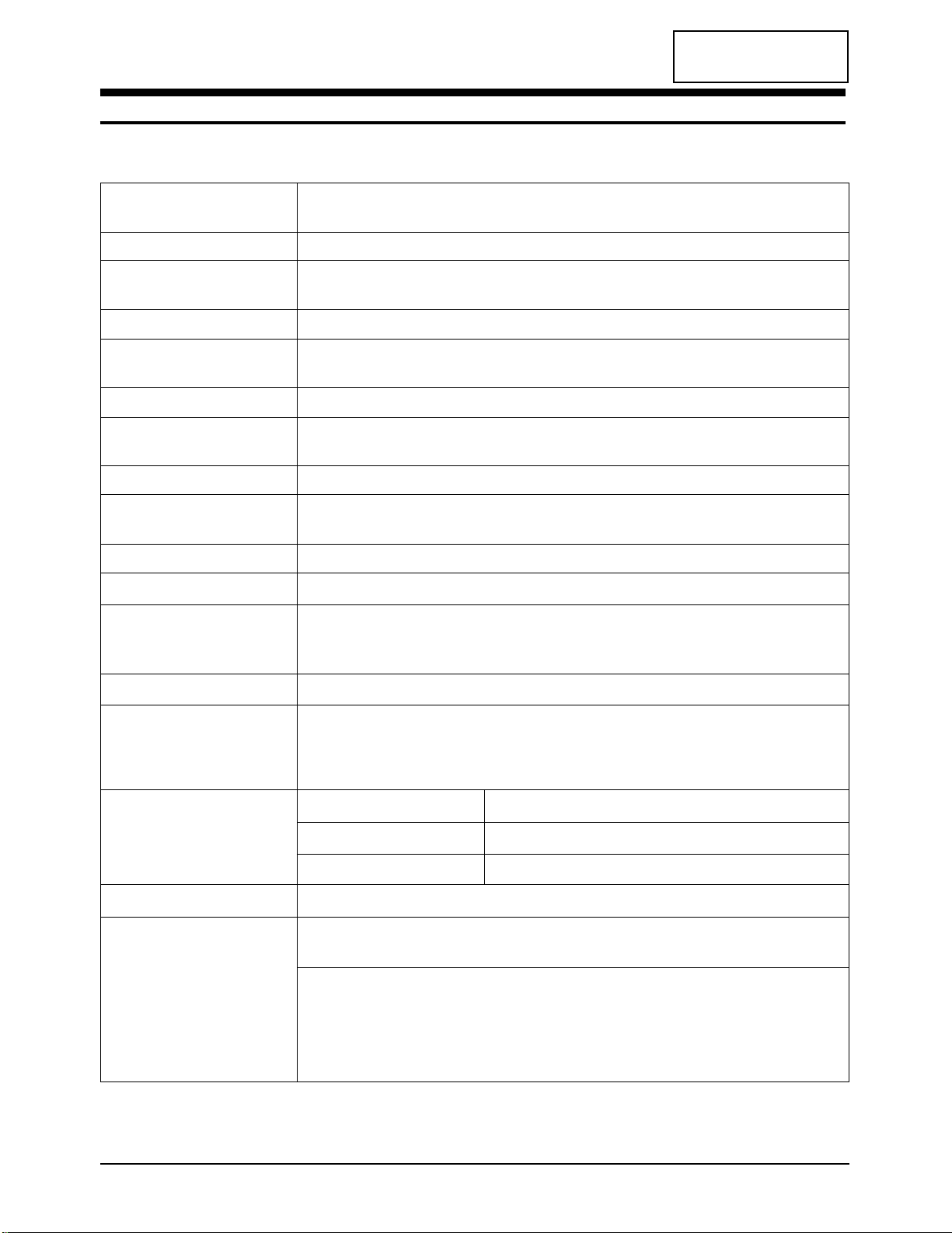
2-1 Specifications
LCD Panel
TFT-LCD panel, RGB vertical stripe, normally Black, 22-Inch viewable, 0.381 mm x 0.381 mm pixel pitch
Scanning Frequency Horizontal : 30 kHz ~ 48 kHz (Automatic)
Vertical : 60 Hz ~ 75 Hz (Automatic)
Display Colors 16.7 Million colors
Maximum Resolution Horizontal : 1280 Pixels
Vertical : 720 Pixels
Input Video Signal Analog 0.7 Vp-p ± 5% positive at 75 Ω, internally terminated
Input Sync Signal Type : Separate H/V
Level : TTL level
Maximum Pixel Clock rate 70 MHz
Active Display
Horizontal/Vertical
AC power voltage & Frequency
AC 90 ~ 264 Volts, 50~60 Hz, DC14V / 8A
Power Consumption 90 W (Max)
Dimensions
Unit (W x D x H) 23.6 x 7.3 x 18.4 Inches (600 x 185 x 468 mm)
Carton (W x D x H) 27.6 x 21.8 x 10.2 Inches (702 x 553 x 260 mm)
Weight (Unit/Gross) 8.8 kg (19.4 lbs) / 15.3 kg (33.7 lbs)
Environmental Considerations Operating Temperature : 50 °F ~ 104 °F (10 °C ~ 40 °C)
Humidity : 10 % ~ 80 %
Storage Temperature : -4 °F ~ 113 °F (-20 °C ~ 45 °C)
Humidity : 5 % ~ 95 %
TV System
Antenna Input 75Ω, Coaxial Cable
– MAX Internal speaker Out : Right => 7W
Left => 7W
Sound Characteristic
– BASS Control Range : -12 dB~ + 12 dB
– TREBLE Control Range : -12 dB~ + 12 dB
– Headphone Out: 5mW max (400m Vrms)
– Output Frequency : RF => 80 Hz ~ 15 kHz
A/V => 80 Hz ~ 15 kHz
LW22A13W 2-1
Item
Description
487.68 mm / 274.32 mm
Tuning Frequency Synthesize
System PAL, SECAM, NTSC 4.4
Sound B/G, D/K, I, L, L’
CONFIDENTIAL
2 Product Specifications
2-2 LW22A13W
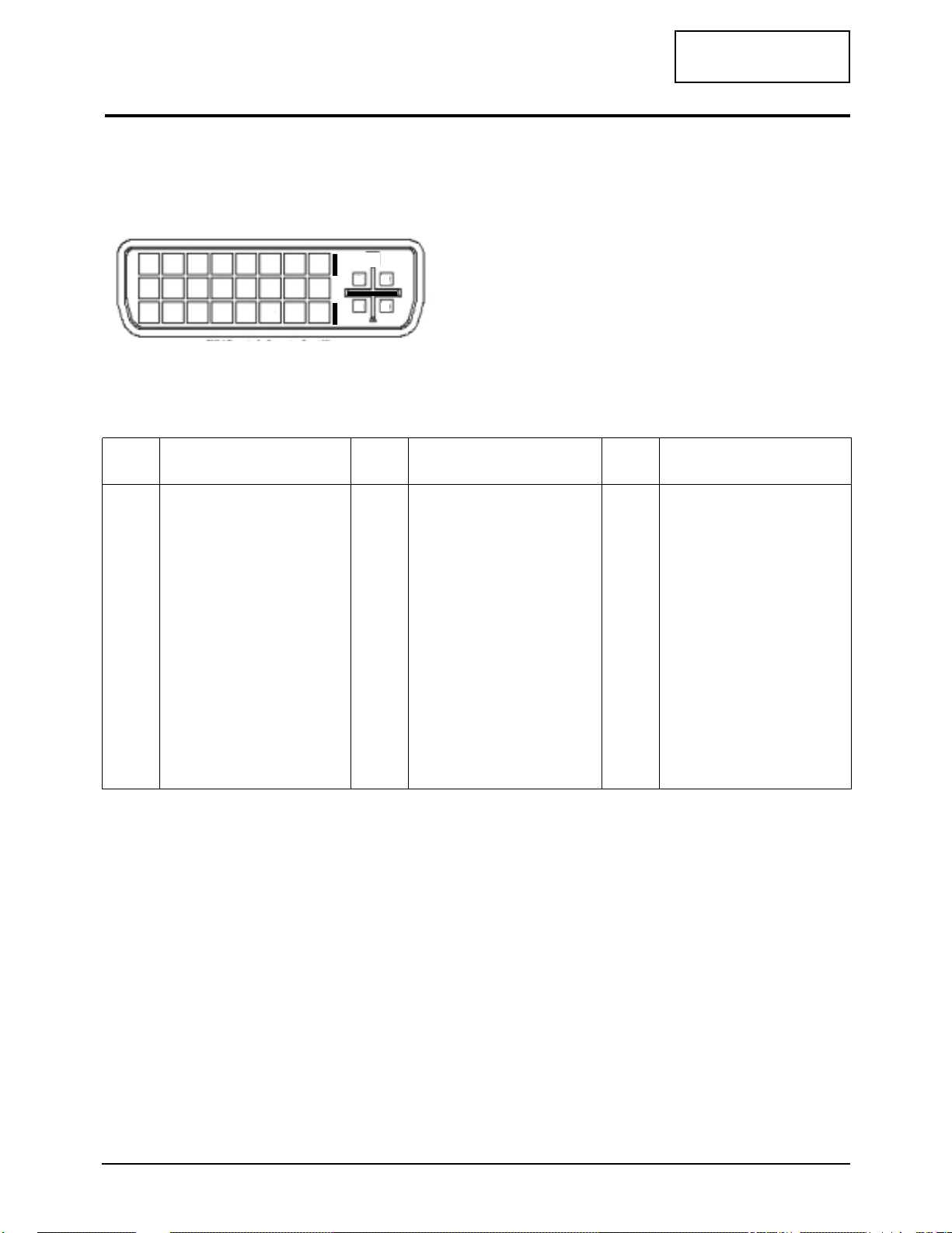
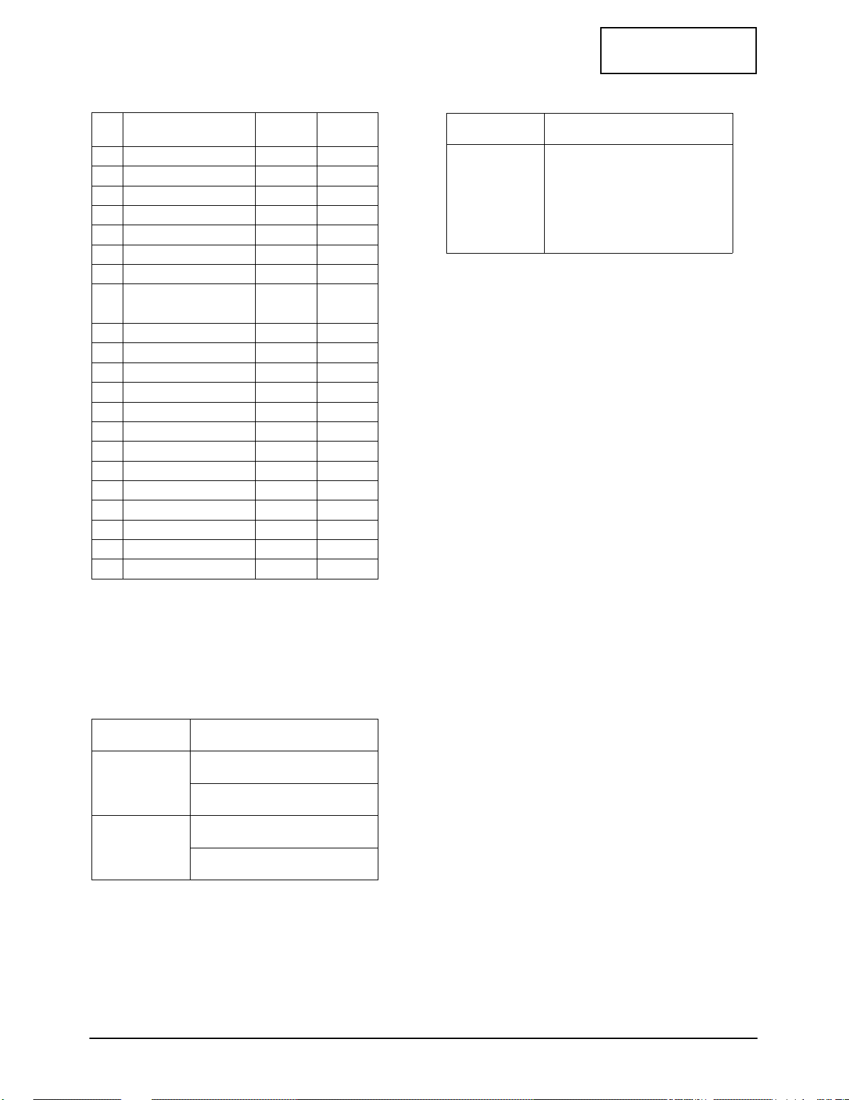
2-2 Pin Assignments
2-2-1 DVI-I (Analog & Digital)
Ref) DVI-D : Digital only
D-SUB : Analog only
Pin No.
Signal Assignment
Pin No.
Signal Assignment
Pin No.
Signal Assignment
1
2
3
4
5
6
7
8
9
10
RX2RX2+
GND
NC
NC
DDC Clock (SCL)
DDC Data (SDA)
Analog Vertical Sync.
RX1RX1+
11
12
13
14
15
16
17
18
19
20
GND
NC
NC
DDC Input Power(+5V)
Self laster
Output Signal Connection
RX0RX0+
GND
NC
21
22
23
24
C1
C2
C3
C4
NC
GND
RXCRXC+
Analog Red
Analog Green
Analog Blue
Analog Horizontal Sync.
1234567 8
9 10111213141516
17 18 19 20 21 22 23 24
C1 C2
C4
C3
DVI-I Receptacle Connector Front View
2 Product Specifications
LW22A13W 2-3
CONFIDENTIAL
CVBS
Audio L
GND
Audio R
GND
Pin
Separate
1
2
3
4
5
GND
Y
C
GND
GND
2-2-4 S-Video
2-2-2 SCART1, SCART2
RCA White
RCA Red
2-2-3 A/V
RCA Yellow
1
2
3
4
5
6
7
8
9
10
11
12
13
14
15
16
17
18
19
20
21
Items Scart1 Scart2
Pin
No
Audio Out (R;500mV/1KΩ)
Audio IN (R;500mV/10KΩ)
Audio Out (L;500mV/1KΩ)
Audio Common GND
Blue GND
Audio IN (L;500mV/10K)
Blue IN (700mV/75Ω)
Function S/W
(0~2V/9, 5V~12V)
Green GND
No Connection
Green IN (700mV/75Ω)
No connection
Red GND
F/B GND
Red IN (700mV/75Ω)
RGB F/B (0~0, 4V/1~3V)
Video Output GND
Video Input GND
CVBS Out (1V/75Ω)
CVBS IN (1V/75Ω)
Common GND
OO
O
O
O
O
O
O
O
O
O
O
O
O
O
O
O
O
O
O
O
O
O
O
O
O
O
O
O
O
O
O
O
O
O
O
2 Product Specifications
2-4 LW22A13W
CONFIDENTIAL
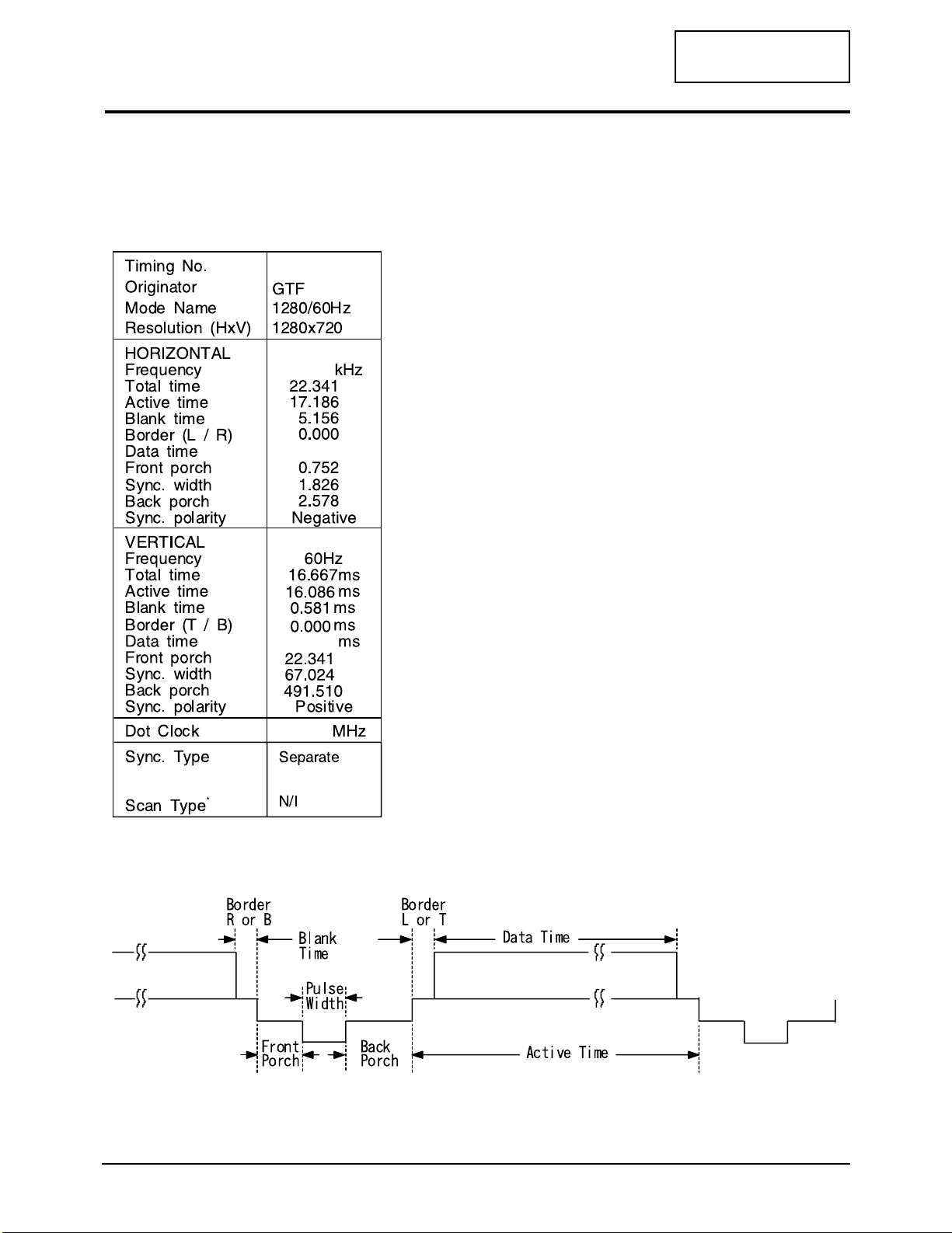
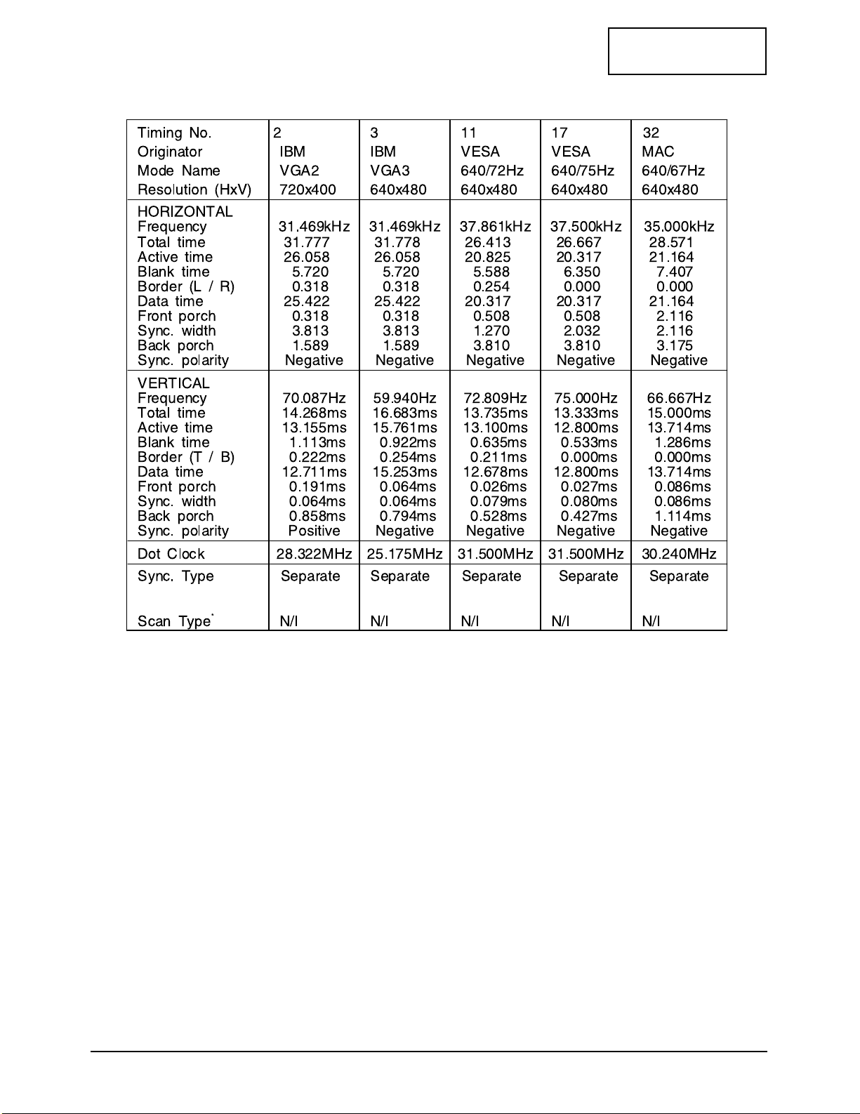
2-3 Timing Chart
This section of the service manual describes the timing that the computer industry recognizes as standard
for computer-generated video signals.
µs
44.769
17.186
16.086
74.841
µs
µs
µs
µs
µs
µs
µs
µs
µs
µs
2-3-1 LCD Panel Mode : 1 mode
✻ N/C : Non-Interlaced, I : Interlaced
2 Product Specifications
LW22A13W 2-5
CONFIDENTIAL
2-3-2 Supported Modes (1)
µs
µs
µs
µs
µs
µs
µs
µs
µs
µs
µs
µs
µs
µs
µs
µs
µs
µs
µs
µs
µs
µs
µs
µs
µs
µs
µs
µs
µs
µs
µs
µs
µs
µs
µs
µs
µs
µs
µs
µs

2 Product Specifications
2-6 LW22A13W
CONFIDENTIAL
2-3-2 Supported Modes (2)
µs
µs
µs
µs
µs
µs
µs
µs
µs
µs
µs
µs
µs
µs
µs
µs
µs
µs
µs
µs
µs
µs
µs
µs
µs
µs
µs
µs
µs
µs
µs
µs
LW22A13W 3-1
CONFIDENTIAL
3 Disassembly and Reassembly
This section of the service manual describes the disassembly and reassembly procedures for the
LW22A13W monitor.
WARNING: This monitor contains electrostatically sensitive devices. Use caution when handling
these components.
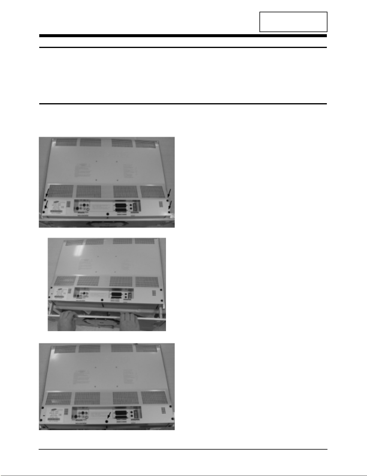
3-1 Disassembly
Cautions:1. Disconnect the monitor from the power source before disassembly.
2. Follow these directions carefully; never use metal instruments to pry apart the cabinet.
1. Remove 4 screws of the cover rear.
2. Remove the stand from LCD-TV.
3. Remove 1 screw of the cover rear.
CONFIDENTIAL
3 Disassembly and Reassembly
3-2 LW22A13W
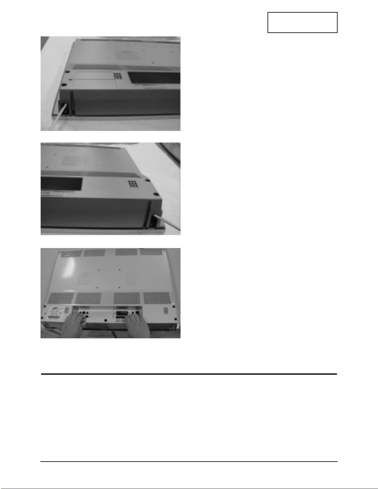
3-2 Reassembly
Reassembly procedures are in the reverse order of Disassembly procedures.
4. Insert a screw driver into upper groove of
stand fitting hole and lift up right & left side
respectively.
5. Pull the cover rear
CONFIDENTIAL
LW22A13W 4-1
4 Alignments and Adjustments
4-1 General Alignment Instuction
1. Usually, a color TV-VCR needs only slight touch-up adjustment upon installation.
Check the basic characteristics such as height, horizontal and vertical sync.
2. Use the specified test equipment or its equivalent.
3. Correct impedance matching is essential.
4. Avoid overload. Excessive signal from a sweep generator might overload the front-end
of the TV. When inserting signal markers, do not allow the marker generator to distort
test result.
5. Connect the TV only to an DC power source with voltage and frequency as specified on
the backcover nameplate.
6. Do not attempt to connect or disconnect any wire while the TV is turned on. Make sure
that the power cord is disconnected before replacing any parts.
7. To protect aganist shock hazard, use an isolation transformer.
4 Alignments and Adjustments
4-2 LW22A13W
CONFIDENTIAL
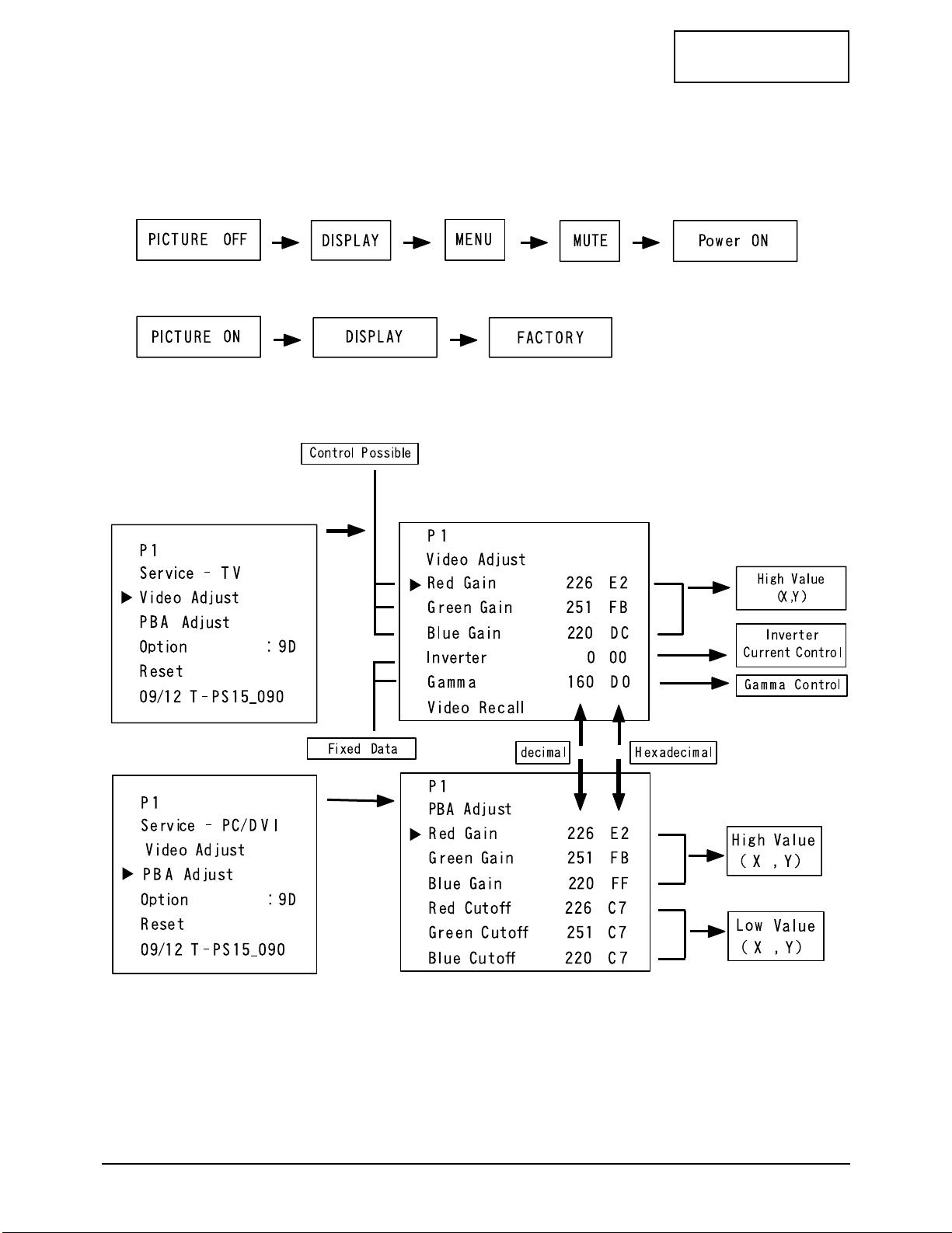
4-2 Factory Mode Adjustments
4-2-1 Entering Factory Mode
1. To enter “Service Mode” Press the remote - control keys in this sequence :
- If you do not have Factory remote - control
- If you have Factory remote - control
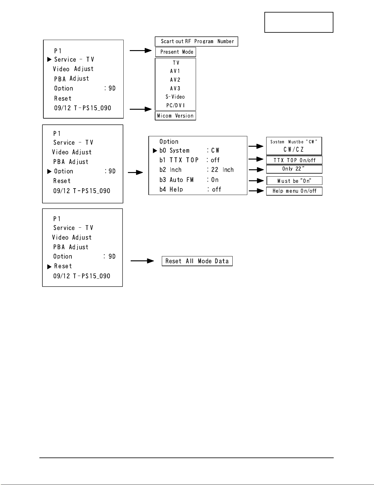
4-2-2 Factory Mode Tree
4 Alignments and Adjustments
LW22A13W 4-3
CONFIDENTIAL

Memo
4 Alignments and Adjustments
4-4 LW22A13W
CONFIDENTIAL
CONFIDENTIAL
LW22A13W 5-1
5 Troubleshooting
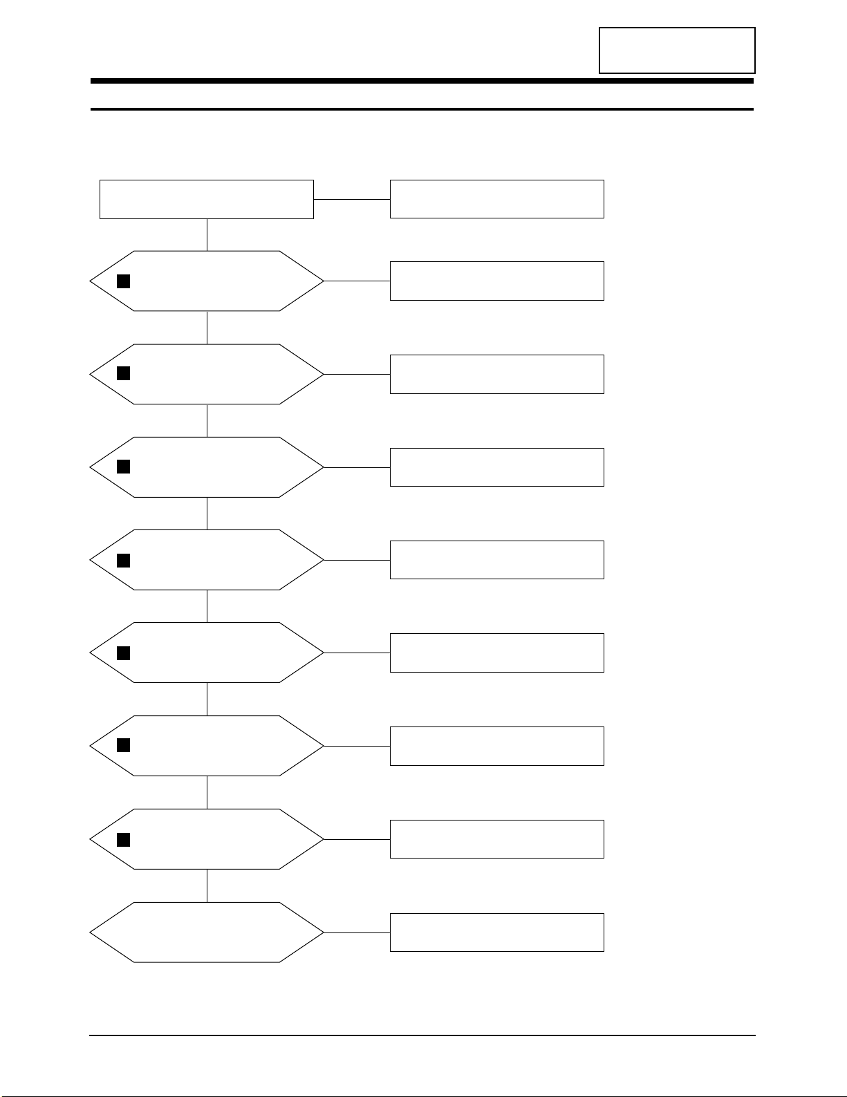
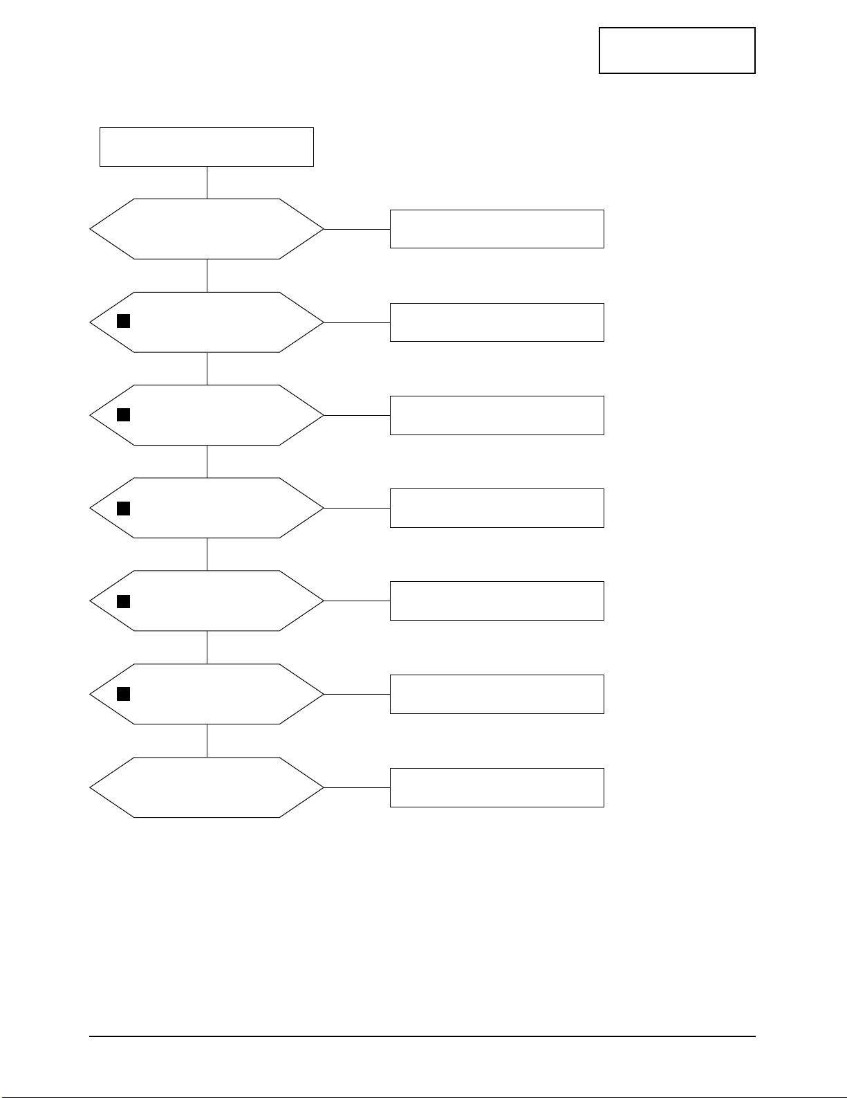
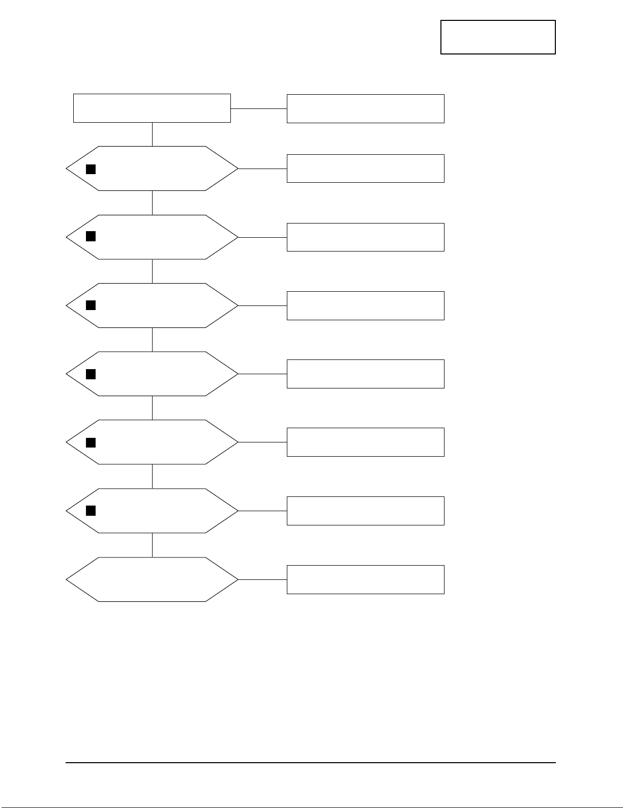
5-1 No Power
Does proper DC 14V
appear at Pin 1 of CN205?
Change a 14V adaptor. (BN44-00051C)
LAMP off, Power indicator LED off.
Yes
Yes
No
Check a connection the 14V adapter?
No
Does proper DC 14V
appear at C847?
Check a connection the 6 Pin hamess and
change a input board assy. (BN59-00339A)
Yes
No
Does proper DC +3.3V_A,
+3.3V_B appear at
C826, C867?
IC801 or IC805 are bad.
Change main assy. (BN94-00400A)
Yes
No
Does proper DC +2.5V_A,
+2.5V_B appear at
C827, C813?
IC802 or IC806 are bad.
Change main assy. (BN94-00400A)
Yes
No
Does proper DC +5V_A, +5V,
+5V_LVDS appear at
C889, C865, CP133?
IC810 or IC804 or ICP22 are bad.
Change main assy. (BN94-00400A)
Yes
No
Does proper DC +12V_3
appear at C841?
ICP23 is bad.
Change main assy. (BN94-00400A)
Yes
No
Does proper DC +8V
appear at C843?
IC843 is bad.
Change main assy. (BN94-00400A)
Yes
No
A power is supplied to set.
Check a other function. (No picture part)
Replace a assy LCD panel. (BN91-00388L)
No
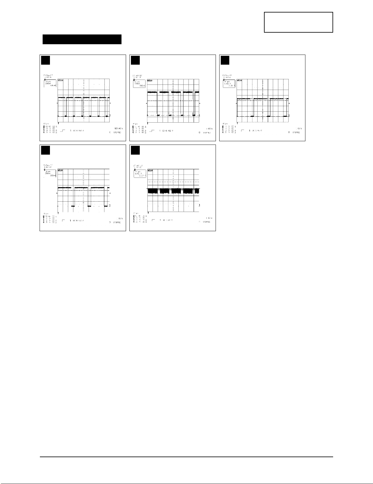
1
2
3
4
5
6
7
5 Troubleshooting
5-2 LW22A13W
CONFIDENTIAL
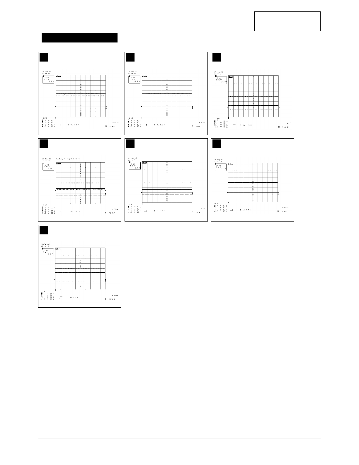
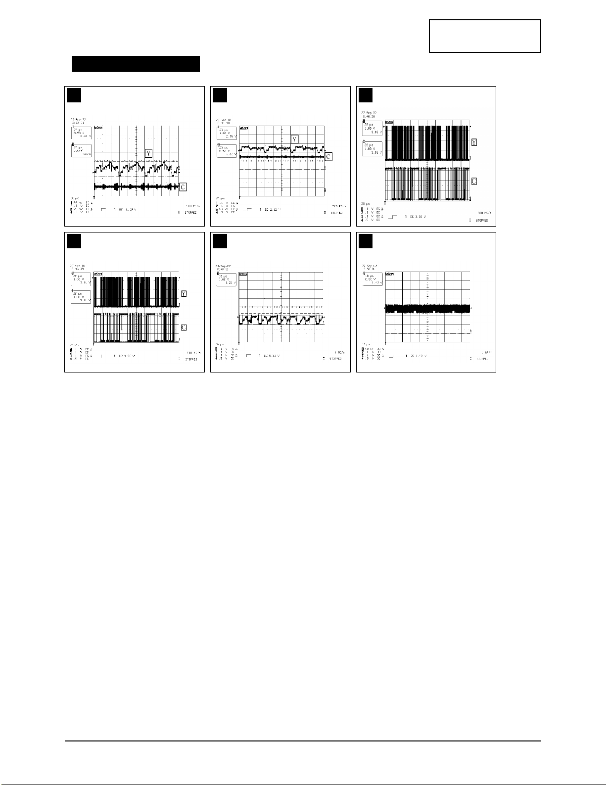
1 2 3
4 5 6
7
WAVEFORMS

5 Troubleshooting
LW22A13W 5-3
CONFIDENTIAL
5-2 No Video (Analog PC Signal)
Check the PC signal and check
connection of FPC DVI cable?
Input a analog signal and
connected cable.
Power indicator is green,
Lamp on, No video.
Yes
Yes
No
Does the signal appear at
#18, 16, 14 (R, G, B) of CN100?
Change FPC cable (CN100) or change a
input board assy. (BN59-00339A)
Yes
No
Does the signal appear at
output of IC350?
(#70_R, #2_G, #12_B)
IC350 is bad.
Change main board assy. (BN94-00400A)
Yes
No
Does the signal appear at
output of [#1_R(IC001),
#1_G(ICP19), #15_B(IC001)]?
IC001 or ICP18 or ICP19 are bad.
Change main board assy. (BN94-00400A)
Yes
No
Does the signal appear at CR01,
CG01, CB01 of R, G, B output?
IC200 is bad.
Change main board assy. (BN94-00400A)
Yes
No
Does the clock pulse appear at
output of RA311~RA313?
IC300 or IC901 are bad.
Change main board assy. (BN94-00400A)
Yes
No
Check a LVDS cable.
Replace a assy LCD panel.
(BN91-00388L)
Please, call to Samsung Co, LTD.
No
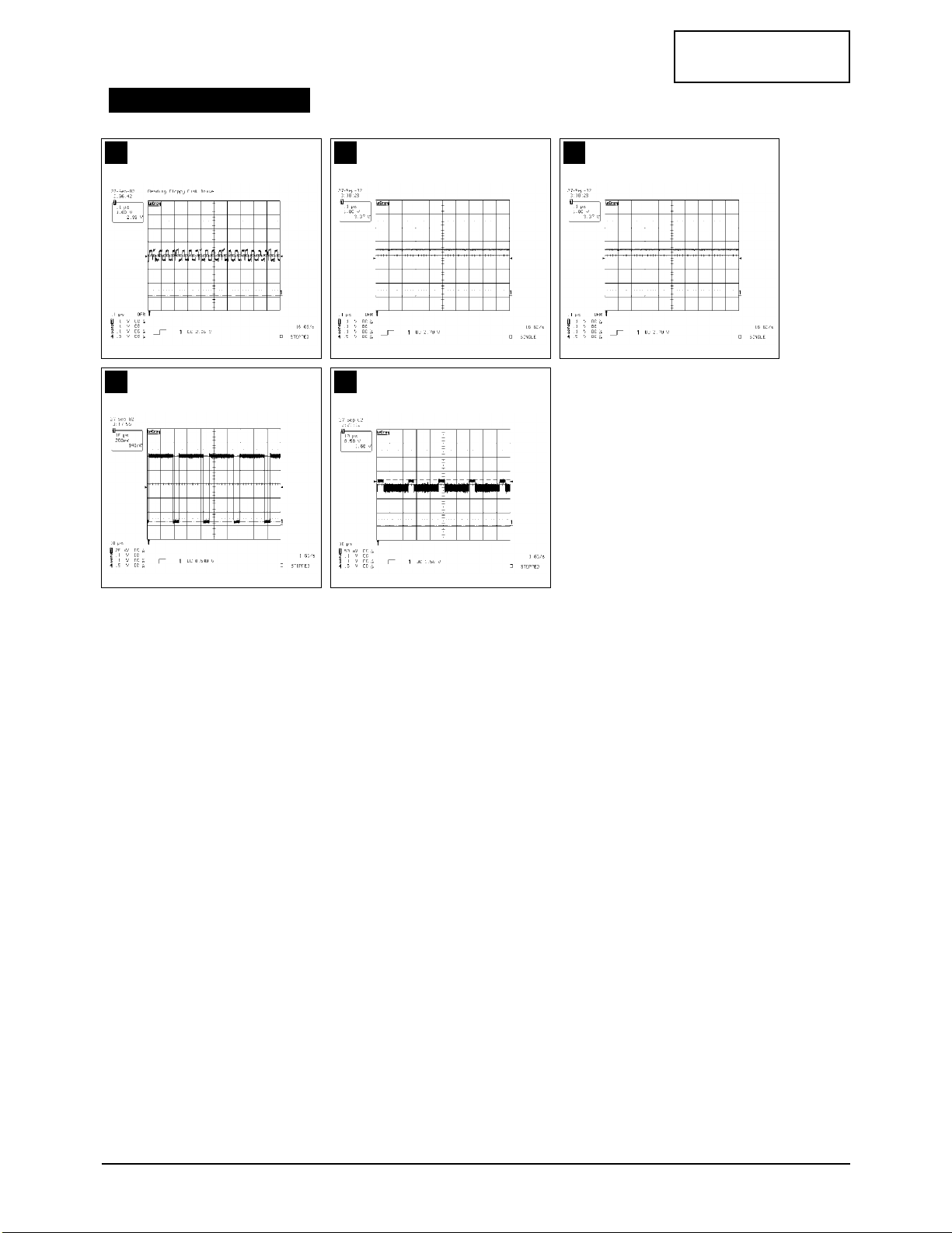
8
9
10
11
12
5 Troubleshooting
5-4 LW22A13W
CONFIDENTIAL
8 9 10
11 12
WAVEFORMS
5 Troubleshooting
LW22A13W 5-5
CONFIDENTIAL
5-3 No Video (Digital PC Signal)
Check the PC signal and check
connection of FPC DVI cable?
Input a digital signal and
connected cable.
Power indicator is green,
Lamp on, No video.
Yes
Yes
No
Does the clock pulse appear at
#5~12 (Data, Clk +/-) of CN100?
Change FPC cable. (CN100)
Change a input board assy. (BN59-00339A)
Yes
No
Does the clock pulse appear at
output at Rap18~RAP21,
Rap28, 29 of ICP18, ICP19?
ICP01 is bad.
Change main board assy. (BN94-00400A)
Yes
No
Does the signal appear at
output of [#1_R(IC001),
#1_G(ICP19), #15_B(IC001)]?
IC001 or ICP18 or ICP19 are bad.
Change main board assy. (BN94-00400A)
Yes
No
Does the signal appear at CR01,
CG01, CB01 of R, G, B output?
IC200 is bad.
Change main board assy. (BN94-00400A)
Yes
No
Does the clock appear at
output of RA311~RA313?
IC300 or IC901 are bad.
Change main board assy. (BN94-00400A)
Yes
No
Check a LVDS cable.
Replace a assy LCD panel.
(BN91-00388L)
Please, call to Samsung Co, LTD.
No
13
14
15
16
17
5 Troubleshooting
5-6 LW22A13W
CONFIDENTIAL
13 14 15
16 17
WAVEFORMS

5 Troubleshooting
LW22A13W 5-7
CONFIDENTIAL
5-4 No Picture (Tuner_CVBS)
Does the signal appear at R2?
Check the DC voltage. (#4 of tuner) : 10V~33V
Change a input board assy. (BN59-00339A)
Power indicator is off,
Lamp on, No picture.
Yes
Yes
No
Connect the RF cable and
check RF signal.
No
Does the signal appear at
C042(#1) of input?
Change FPC cable. (CN101)
Change a input board assy. (BN59-00339A)
Yes
No
Does the clock pulse appear at
3230Y, C_OUT(0:7) of IC010?
IC010 is bad.
Change main board assy. (BN94-00400A)
Yes
No
Does the clock pules appear at
output of IC002~IC005?
IC001 or ICP18 are bad.
Change main board assy. (BN94-00400A)
Yes
No
Does the signal appear at CR01,
CG01, CB01 of R, G, B output?
IC200 is bad.
Change main board assy. (BN94-00400A)
Yes
No
Does the clock appear at
output of RA311~RA313?
IC300 or IC901 are bad.
Change main board assy. (BN94-00400A)
Yes
No
Check a LVDS cable.
Replace a assy LCD panel.
(BN91-00388L)
Please, call to Samsung Co, LTD.
No
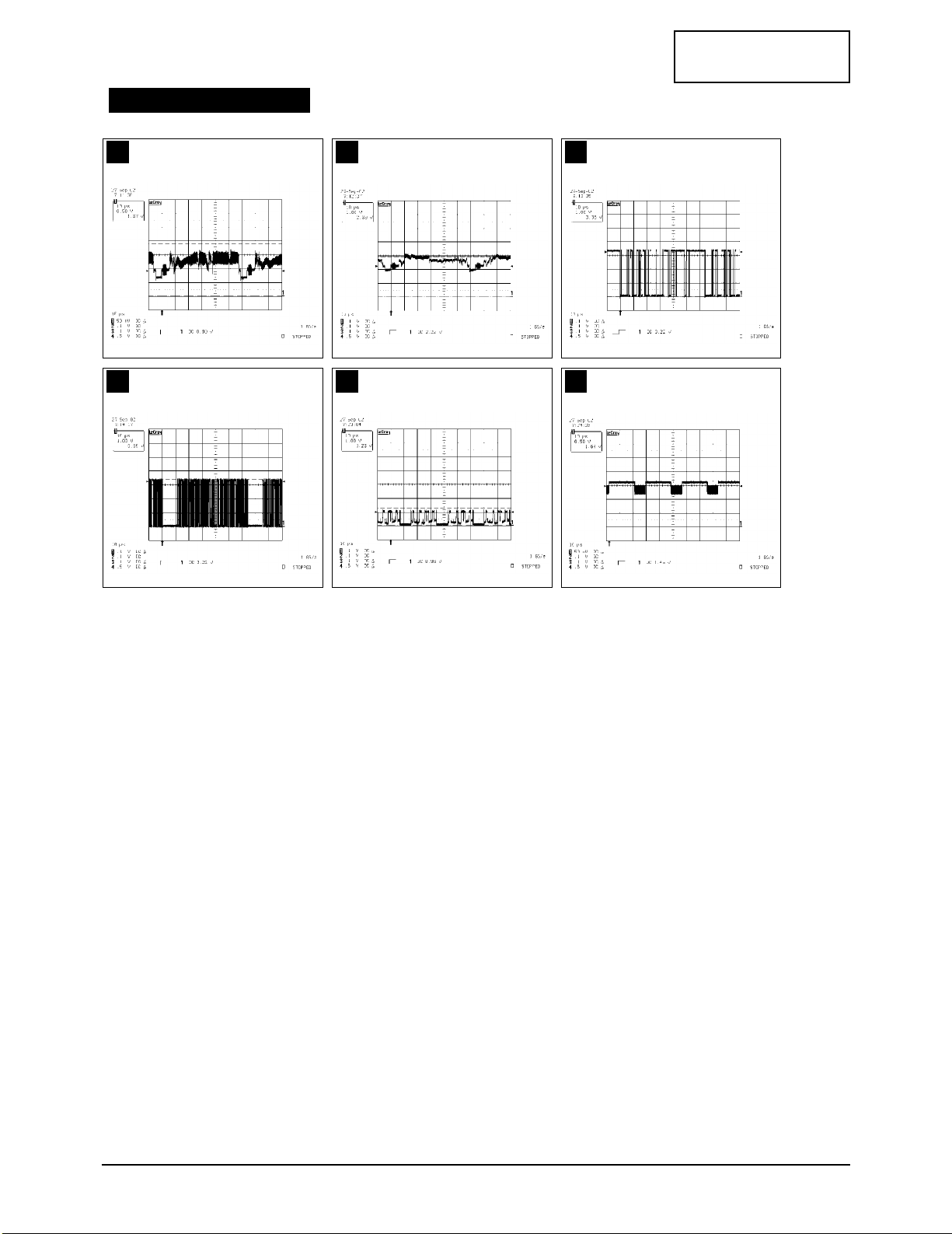
19
18
20
21
22
23
5 Troubleshooting
5-8 LW22A13W
CONFIDENTIAL
18 19 20
21 22 23
WAVEFORMS
5 Troubleshooting
LW22A13W 5-9
CONFIDENTIAL
5-5 No Picture (Video_CVBS)
Does the signal appear at R8?
Change s video cable.
Change a input board assy. (BN59-00339A)
Power indicator is off,
Lamp on, No picture.
Yes
Yes
No
Connect the video cable.
Operating a video player.
No
Does the signal appear at
C046(#8) of input IC011?
Change FPC cable. (CN101)
Change a input board assy. (BN59-00339A)
Yes
No
Does the clock pulse appear at
output of IC006~IC009?
IC010 is bad.
Change main board assy. (BN94-00400A)
Yes
No
Does the clock pules appear at
output of IC002~IC005?
IC001 or ICP18 are bad.
Change main board assy. (BN94-00400A)
Yes
No
Does the signal appear at CR01,
CG01, CB01 of R, G, B output?
IC200 is bad.
Change main board assy. (BN94-00400A)
Yes
No
Does the clock pulse appear at
output of RA311~RA313?
IC300 or IC901 are bad.
Change main board assy. (BN94-00400A)
Yes
No
Check a LVDS cable.
Replace a assy LCD panel.
(BN91-00388L)
Please, call to Samsung Co, LTD.
No
25
24
26
27
28
29

5 Troubleshooting
5-10 LW22A13W
CONFIDENTIAL
24 25 26
27 28 29
WAVEFORMS

5 Troubleshooting
LW22A13W 5-11
CONFIDENTIAL
5-6 No Picture (S-Video_Y, C)
Does the signal
appear at R9, R10 (Y, C)?
Chagne a S-Video cable.
Change a input board assy. (BN59-00339A)
Power indicator is off,
Lamp on, No picture.
Yes
Yes
No
Connect the S-Video cable.
Operating a video player.
No
Does the signal appear at
C044(#5, Y), C045(#6, C) of
input IC011?
Change FPC cable. (CN101)
Change a input board assy. (BN59-00339A)
Yes
No
Does the clock pulse appear at
output of IC006~IC009?
IC010 is bad.
Change main board assy. (BN94-00400A)
Yes
No
Does the clock pulse appear at
output of IC002~IC005?
IC001 or ICP18 are bad.
Change main board assy. (BN94-00400A)
Yes
No
Does the signal appear at CR01,
CG01, CB01 of R, G, B output?
IC200 is bad.
Change main board assy. (BN94-00400A)
Yes
No
Does the clock pulse appear at
output of RA311~RA313?
IC300 or IC901 are bad.
Change main board assy. (BN94-00400A)
Yes
No
Check a LVDS cable.
Replace a assy LCD panel.
(BN91-00388L)
Please, call to Samsung Co, LTD.
No
31
30
32
33
34
35
5 Troubleshooting
5-12 LW22A13W
CONFIDENTIAL
30 31 32
33 34 35
WAVEFORMS

5 Troubleshooting
LW22A13W 5-13
CONFIDENTIAL
5-7 No Picture (SCART1, 2_CVBS : Low Resolution)
Does the signal appear at
R98, R102 (SC1, 2 CVBS)?
Chagne a scart cable.
Change a input board assy. (BN59-00339A)
Power indicator is off,
Lamp on, No picture.
Yes
Yes
No
Connect the scart cable.
Operating a video player.
No
Does the signal appear at
C043(#3, SC1), C048(#10, SC2)
of input IC011?
Change FPC cable. (CN102)
Change a input board assy. (BN59-00339A)
Yes
No
Does the clock pulse appear at
output of IC006~IC009?
IC010 is bad.
Change main board assy. (BN94-00400A)
Yes
No
Does the clock pulse appear at
output of IC002~IC005?
IC001 or ICP18 are bad.
Change main board assy. (BN94-00400A)
Yes
No
Does the signal appear at CR01,
CG01, CB01 of R, G, B output?
IC200 is bad.
Change main board assy. (BN94-00400A)
Yes
No
Does the clock pulse appear at
output of RA311~RA313?
IC300 or IC901 are bad.
Change main board assy. (BN94-00400A)
Yes
No
Check a LVDS cable.
Replace a assy LCD panel.
(BN91-00388L)
Please, call to Samsung Co, LTD.
No
37
36
38
39
40
41
 Loading...