

Samsung LW20M21C Service manual

TFT-LCD TV
Chassis Model
VC17EO LW17M24C
VE20EO LW20M21C
Manual
SERVICE
TFT-LCD TV CONTENTS
1. Precautions
2. Product Specifications
3. Disassembly & Reassembly
4. Alignment & Adjustments
5. Troubleshooting
6. Exploded View & Parts List
7. Electrical Parts List
8. Block Diagram
9. Wiring Diagram
10. PCB Layout
11. Schematic Diagrams
12. Panel Description

1-1-1 Warnings
1. For continued safety, do not attempt to modify the circuit
board.
2. Disconnect the AC power and DC Power Jack before
servicing.
1-1-2 Servicing the LCD TV
1. When servicing the LCD TV Disconnect the AC line
cord from the AC outlet.
2. It is essential that service technicians have an accurate
voltage meter available at all times. Check the
calibration of this meter periodically.
1-1-3 Fire and Shock Hazard
Before returning the LCD TV to the user, perform the
following safety checks:
1. Inspect each lead dress to make certain that the leads are
not pinched or that hardware is not lodged between the
chassis and other metal parts in the LCD TV.
2. Inspect all protective devices such as nonmetallic control
knobs, insulating materials, cabinet backs, adjustment
and compartment covers or shields, isolation resistorcapacitor networks, mechanical insulators, etc.
3. Leakage Current Hot Check (Figure 1-1):
WARNING: Do not use an isolation
transformer during
this test.
Use a leakage current tester or a metering system that
complies with American National Standards Institute
(ANSI C101.1, Leakage Current for Appliances), and
Underwriters Laboratories (UL Publication UL1410,
59.7).
Figure 1-1. Leakage Current Test Circuit
4. With the unit completely reassembled, plug the AC line
cord directly into a 220V AC outlet. With the unit’s AC
switch first in the ON position and then OFF, measure
the current between a known earth ground (metal water
pipe, conduit, etc.) and all exposed metal parts,
including: metal cabinets, screwheads and control shafts.
The current measured should not exceed 0.5 milliamp.
Reverse the power-plug prongs in the AC outlet and
repeat the test.
1-1-4 Product Safety Notices
Some electrical and mechanical parts have special safetyrelated characteristics which are often not evident from visual
inspection. The protection they give may not be obtained by
replacing them with components rated for higher voltage,
wattage, etc. Parts that have special safety characteristics are
identified by on schematics and parts lists. A substitute
replacement that does not have the same safety characteristics
as the recommended replacement part might create shock, fire
and / or other hazards. Product safety is under review
continuously and new instructions are issued whenever
appropriate.
1 Precautions
LW17M24C/LW20M21C 1-1
1 Precautions
Follow these safety, servicing and ESD precautions to prevent damage and to protect against potential hazards such as electrical
shock.
1-1 Safety Precautions
DEVICE
UNDER
TEST
TEST ALL
EXPOSED METAL
SURFACES
(READING SHOULD
NOT BE ABOVE 0.5mA)
LEAKAGE
CURRENT
TESTER
2-WIRE CORD
ALSO TEST WITH
PLUG REVERSED
(USING AC ADAPTER
PLUG AS REQUIRED)
EARTH
GROUND
!

1-2-1 General Servicing
Precautions
1. Always unplug the unit’s AC power cord from the AC
power source and disconnect the DC Power Jack before
attempting to:
(a) remove or reinstall any component or assembly, (b)
disconnect PCB plugs or connectors, (c) connect a test
component in parallel with an electrolytic capacitor.
2. Some components are raised above the printed circuit
board for safety. An insulation tube or tape is sometimes
used. The internal wiring is sometimes clamped to
prevent contact with thermally hot components. Reinstall
all such elements to their original position.
3. After servicing, always check that the screws,
components and wiring have been correctly reinstalled.
Make sure that the area around the serviced part has not
been damaged.
1. Immediately before handling any semiconductor
components or assemblies, drain the electrostatic charge
from your body by touching a known earth ground.
Alternatively, wear a discharging wrist-strap device. To
avoid a shock hazard, be sure to remove the wrist strap
before applying power to the LCD TV.
2. After removing an ESD-equipped assembly, place it on a
conductive surface such as aluminum foil to prevent
accumulation of an electrostatic charge.
3. Do not use freon-propelled chemicals. These can
generate electrical charges sufficient to damage ESDs.
4. Use only a grounded-tip soldering iron to solder or
desolder ESDs.
5. Use only an anti-static solder removal device. Some
solder removal devices not classified as “anti-static” can
generate electrical charges sufficient to damage ESDs.
4. Check the insulation between the blades of the AC plug
and accessible conductive parts (examples: metal panels,
input terminals and earphone jacks).
5. Insulation Checking Procedure: Disconnect the power
cord from the AC source and turn the power switch ON.
Connect an insulation resistance meter (500 V) to the
blades of the AC plug.
The insulation resistance between each blade of the AC
plug and accessible conductive parts (see above) should
be greater than 1 megohm.
6. Always connect a test instrument’s ground lead to the
instrument chassis ground before connecting the positive
lead; always remove the instrument’s ground lead last.
6. Do not remove a replacement ESD from its protective
package until you are ready to install it. Most
replacement ESDs are packaged with leads that are
electrically shorted together by conductive foam,
aluminum foil or other conductive materials.
7. Immediately before removing the protective material
from the leads of a replacement ESD, touch the
protective material to the chassis or circuit assembly into
which the device will be installed.
Caution: Be sure no power is applied to
the chassis or circuit and
observe all other safety
precautions.
8. Minimize body motions when handling unpackaged
replacement ESDs. Motions such as brushing clothes
together, or lifting your foot from a carpeted floor can
generate enough static electricity to damage an ESD.
1 Precautions
1-2 LW17M24C/LW20M21C
1-3 Electrostatically Sensitive Devices (ESD) Precautions
Some semiconductor (solid state) devices can be easily damaged by static electricity. Such components are commonly called
Electrostatically Sensitive Devices (ESD). Examples of typical ESD are integrated circuits and some field-effect transistors. The
following techniques will reduce the incidence of component damage caused by static electricity.
1-2 Servicing Precautions
WARNING: An electrolytic capacitor installed with the wrong polarity might explode.
Caution: Before servicing units covered by this service manual, read and follow the Safety Precautions
section of this manual.
Note: If unforeseen circumstances create conflict between the following servicing precautions and any of the safety
precautions, always follow the safety precautions.

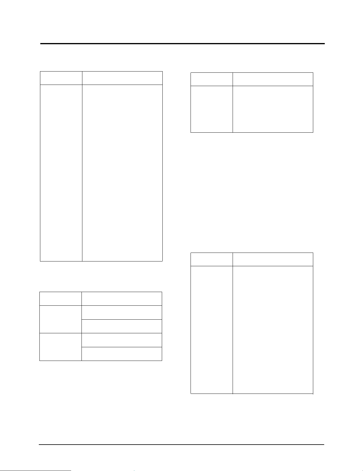
2 Product Specifications
2-1 LW17M24C, LW20M21C Specifications
LCD Panel
TFT-LCD panel, RGB vertical stripe, normaly white, 17-Inch viewable, 0.264 (H) x 0.264(V)mm pixel pitch
TFT-LCD panel, RGB vertical stripe, normaly white, 20-Inch viewable, 0.2125(H) x 0.6375(V) mm pixel pitch
Scanning Frequency Horizontal : 30 kHz ~ 80 kHz (Automatic) Horizontal : 28 kHz ~ 33 kHz (Automatic)
Vertical : 50 Hz ~ 75 Hz (Automatic) Vertical : 50 Hz ~ 70 Hz (Automatic)
Display Colors 16.2 Million colors
Maximum Resolution Horizontal : 1280 Pixels Horizontal : 640 Pixels
Vertical : 1024 Pixels Vertical : 480 Pixels
Input Video Signal Analog 0.7 Vp-p ± 5% positive at 75 Ω, internally terminated
Input Sync Signal Type : Seperate H/V
Level : TTL level
Active Display
Horizontal/Vertical
AC power voltage & Frequency
AC 100 ~ 240V, 50 ~ 60 Hz
Power Consumption 45 W 55 W
Dimensions(W x D x H)
Set
16.44 x 7.59 x 16.72 Inches (417.5 x 192.9 x 424.6 mm)(State of stand installed) 18.86 x 8.85 x 18.07 Inches (479 x 224.8 x 459.1 mm) (State of stand installed)
18.86 x 2.94 x 17.18 Inches (479 x 74.7 x 436.4 mm) (State of stand disassembled)
16.44 x 4.95 x 16.72 Inches (417.5 x 125.7 x 424.6 mm)(State of Wall mount) 18.86 x 5.51 x 20.42 Inches (479 x 139.9 x 518.6 mm) (Without Stand of Wall mount)
Package 21.1 x 7.2 x 20.1 Inches (537 x 183 x 511 mm
)
22.60 x 23.35 x 8.27 Inches (574 x 593 x 210 mm)
Weight
Set / Package 4.95 Kg (10.91Ibs) / 7.0 Kg (15.43 lbs)
7.35 Kg (16.20 Ibs) (State of stand installed) / 10 Kg (22.05 lbs)
Environmental Considerations Operating Temperature : 50 °F ~ 104 °F (10 °C ~ 40 °C)
Operating Humidity : 10 % ~ 80 %
Storage Temperature : -4 °F ~ 113 °F (-20 °C ~ 45 °C)
Storage Humidity : 5 % ~ 95 %
TV System
Antena Input 75Ω, Coaxial Cable
– MAX Internal speaker Output : Right => 2.5W
Left => 2.5W
Sound Characteristic
– Headphone Out: 10mW max (3.50 Stereo Jack 32)
– Output Frequency : RF => 80 Hz ~ 15 kHz at -3dB
A/V => 80 Hz ~ 20 kHz at -3dB
2 Product Specifications
LW17M24C/LW20M21C 2-1
Item
Description
LW17M24C
LW20M21C
337.9 mm(H) / 270.3 mm(V) 408 mm(H) / 306 mm(V)
Tunning Frequency Synthesize
System NTSC-M, PAL/ Secam_L(Euro multi)
Sound MONO, STEREO, SAP, A2/Nicam
2 Product Specifications
2-2 LW17M24C/LW20M21C
1
2
3
4
5
6
7
8
9
10
11
12
13
14
15
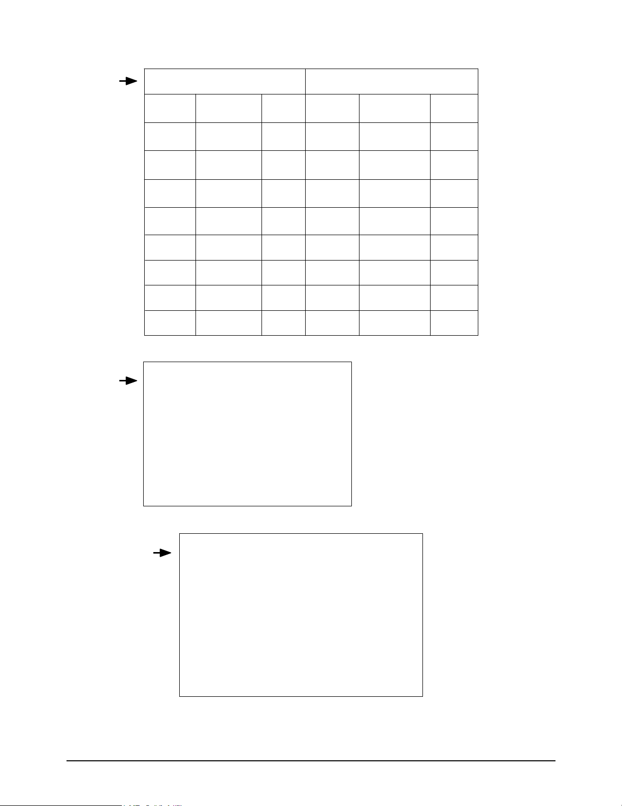
2-2 Pin Assignments
RCA White
RCA Red
CVBS
Audio L
GND
Audio R
GND
2-2-3 A/V
RCA Yellow
Pin
Separate
1
2
3
4
5
GND
Y
C
GND
GND
2-2-2 S-Video
Pin
Separate
Red
Green
Blue
GND
GND (DDC Return)
GND-Red
GND-Green
GND-Blue
No Connection
GND-Sync / Self Test
GND
DDC Data
H - Sync
V - Sync
DDC Clock
2-2-4 D-SUB
1
2
3
4
5
6
7
8
9
10
11
12
13
14
15
16
17
18
19
20
21
No
PIN
Sound R out
Sound R In
Sound L out
GND
GND
Sound L In
Cb
ID
GND
NC
Y
NC
GND
GND
Cr
BL In
GND
GND
Video Out
Video In
GND
2-2-1 Scart
2 Product Specifications
LW17M24C/LW20M21C 2-3
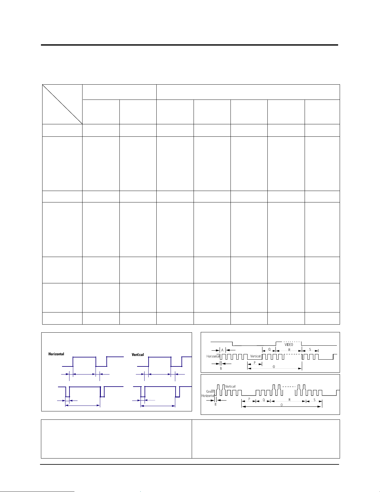
Separate Sync
2-3 Timing Chart
This section of the service manual describes the timing that the computer industry recognizes as standard for
computer-generated video signals.
C D
A
O
E
B
P
Video
Sync
Sync
Video
Q R S
A : Line time total B : Horizontal sync width O : Frame time total P : Vertical sync width
C : Back porch D : Active time Q : Back porch R : Active time
E : Front porch S : Front porch
H/V Composite Sync
Sync-on-Green
79.976
12.504
1.067
1.837
9.481
0.119
75.025
13.329
0.038
0.475
12.804
0.013
135.000
Positive
Positive
Separate
1280/75Hz,50Hz
1280x1024
1024/75Hz
1024 x 768
60.023
16.660
1.219
2.235
13.003
0.203
75.029
13.328
0.050
0.466
12.795
0.017
78.750
Positive
Positive
Separate
31.469
31.777
3.813
1.589
26.058
0.318
70.087
14.268
0.064
0.858
13.155
0.191
28.322
Negative
Positive
Separate
fH (KHz)
A µsec
B µsec
C µsec
D µsec
E µsec
fV (Hz)
O msec
P msec
Q msec
R msec
S msec
Clock
Freq.
(MHz)
Polarity
H.Sync
V.Sync
Remark
IBM(LW17M24C/LW20M21C)
640/75 Hz, 60Hz,
72Hz
640 x 480
800/75 Hz, 56Hz,
60Hz, 72Hz
800 x 600
1024/60Hz
1024 x 768
VGA2/70 Hz
720 x 400
VGA3/60 Hz
640 x 480
Table 2-1 Timing Chart
31.469
31.778
3.813
1.589
26.058
0.318
59.940
16.683
0.064
0.794
15.761
0.064
25.175
Negative
Negative
Separate
37.500
26.667
2.032
3.810
20.317
0.508
75.000
13.333
0.080
0.427
12.800
0.027
31.500
Negative
Negative
Separate
46.875
21.333
1.616
3.232
16.162
0.323
75.000
13.333
0.064
0.448
12.800
0.021
49.500
Positive
Positive
Separate
48.363
20.677
2.092
2.462
15.754
0.369
60.004
16.666
0.124
0.600
15.880
0.062
75.000
Negative
Negative
Separate
Mode
VESA(LW17M24C)
Timing

Memo
2 Product Specifications
2-4 LW17M24C/LW20M21C

3 Disassembly and Reassembly
LW17M24C/LW20M21C 3-1
3 Disassembly and Reassembly
This section of the service manual describes the disassembly and reassembly procedures for the
LW17M24C/LW20M21C TFT-LCD TV.
WARNING: This monitor contains electrostatically sensitive devices. Use caution
when handling these components.
3-1-1 LW17M24C
Cautions: 1. Disconnect the monitor from the power source before disassembly.
2. When IP-BOARD has a defect, the whole PCB ASS’Y, not a single part, should be
replaced.
1. Place LCD TV face down on cushioned table.
Remove 4 screws from the stand.
2. Remove 3 screws from the rear cover and lift up
the rear cover.
3. Remove 13 screws from the boards and remove 2
hold inverter from the boards.
Disconnect inverter cable, speaker cable, control
cable, BRKT AC cable and LVDS cable from the
boards.
4. Lift up the boards. remove 8 screws from the
shield panel.
5. Remove 8 screws from the shield panel.
.Lift up the panel shield. and lift up the panel.

3 Disassembly and Reassembly
3-2 LW17M24C/LW20M21C
1. Place LCD TV face down on cushioned table.
Remove 4 screws from the grip on the stand.
2. Remove 3 screws on stand and disconnect cover
rear after inserting stand completely into stand.
(Note : If stand is loosely inserted into stand, cover
rear can be damaged when disconnected.)
3. Disconnect inverter holder wire from the board and
carefully reomve the silicon glue on the LVDS
cable with a nipper.
4. Disconnect function cable, speaker cable, inverter
cable and LVDS cable from the board.
5. Remove 8 screws from the shield panel and lift up
the panel.
6. Lift up the panel.
This picture shows cover front after disconnecting
the panel from it.
3-1-2 LW20M21C

3 Disassembly and Reassembly
LW17M24C/LW20M21C 3-3
3-2 Reassembly
Reassembly procedures are in the reverse order of disassembly procedures.

Memo
3 Disassembly and Reassembly
3-4 LW17M24C/LW20M21C

4 Alignments and Adjustments
LW17M24C/LW20M21C 4-1
4 Alignments and Adjustments
4-1 General Alignment Instuction
1. Usually, a color TV-VCR needs only slight touch-up adjustment upon installation.
Check the basic characteristics such as height, horizontal and vertical sync.
2. Use the specified test equipment or its equivalent.
3. Correct impedance matching is essential.
4. Avoid overload. Excessive signal from a sweep generator might overload the front-end of the TV.
When inserting signal markers, do not allow the marker generator to distort test result.
5. Connect the TV only to an DC power source with voltage and frequency as specified on
the backcover nameplate.
6. Do not attempt to connect or disconnect any wire while the TV is turned on.
Make sure that the power cord is disconnected before replacing any parts.
7. To protect aganist shock hazard, use an isolation transform.

4-2 Factory Mode Adjustments
4-2-1 Entering Factory Mode
1. To enter “Service Mode” Press the remote -control keys in this sequence :
- If you do not have Factory remote - control
- If you have Factory remote - control
4-2-2 Factory Mode Tree
4 Alignments and Adjustments
4-2 LW17M24C/LW20M21C
1. Calibration
1. Calibration
VCTi
PC
2. Option
INFO Menu
3. W/B
4. ADC
5. VCTi 127
6. ACC/ACM
7. Test Pattern 0
8. Bus Stop off
9. Check Sum 0
10. Reset
T- VNC17(20) - PEU-0003 2004/04/20
(1) RF,VIDEO, S-VIDEO :
Factor y Mo de Cal ib r at ion V CTi Enter
(2) PC : adjust in VGA MODE.
Based on Master device
execute Auto Adjustment in Cross Hatch (also called Combination) (Model : 10, Pattern : 25)
(VI DEO SIGNA L GENE RA TOR M SPG- 925F )
After adjusting 16 Gray Pattern (Model : 10, Pattern : 17)
Fac
tory Mode Cal ibr ati on PC E nt e r
(3) check 4.ADC of Factory Mode. Adjustment can be done as below.
Value variation can be 10~20.
+
_

4 Alignments and Adjustments
LW17M24C/LW20M21C 4-3
3. W/B(1)
3. W/B(2)
R level 128
G level 128
B level 128
R gain 127
G gain 127
B gain 127
g Sub Color 0
g Sub Tint 50
Recall
RF RF
[Initial Data] [A d ju st Dat a]
RemarkAdjustment item
Red l evel A DJ[ 0~255] 128 128
Green level AD J[ 0~255] 128 128
Blue level F IX [0~255] 128 128
Red Gain FI X[ 0~255] 128 135
Green Gain ADJ[ 0~255] 128 135
Blue Gain ADJ [ 0~255] 128 135
gSUB Color FI X[ 0~255] 0 0
gSUB Tint F IX [0~255] 50 50
Factor y Rec al l
*A/S : Micom Initial Data Write
2. Option
1. Video Mute O
2. Auto Power On
3. Panel XGA
4. Inch 15
5. Antenna Osd off
6. TTXList/Flof Flof
7. Auto FM On
8. Acc/ACM 1
9. Gamma LUT O
10. ESM
11. System
On
CW
LW17M24C
Blue level 118FIX
Red Gain 162FIX
LW20M21C
Blue level 119FIX
Red Gain 136FIX
4 Alignments and Adjustments
4-4 LW17M24C/LW20M21C
4. ADC
5. VCT
R Drive
255
G Drive
255
B Drive
255
Sub Contrast
44
Sub Bright
0
Sub Sharp
15
Sub Color
7
Sub Tint
50
Sub Coring
5
RF AGC
0
Vpeaking
6
CTI Gain
3
CTI Coring
5
LMIXOFS
6
PKCF
3
AGCADJ1
32
LTI Gain
15
6. ACC/ ACM
Y Max D
7
Y Scl Thr
64
Y Scl A
5
Y Scl B
0
A Ctrl
0
A Snslp
8
T Dixel
12
Lower End
80
Mid Start
30
Mid End
100
Up Start
40
Low Sn Thr
60
Up Sn Thr
0
Y Min
10
Y Max
255
Ym Div Slp
128
Fr Age
1
Fr App
0
Esm Ctrl
127
VCTi PC
Roff set
set
set
set
set
set
FI X [0~127 ] 46 Rof f F IX[ 0~127] 50
Goff F I X[ 0~127 ] 66 G of f F IX [0~127] 54
Boff F IX [0~127 ] 68 Bof f FI X[ 0~127] 44
Rgai n 0
FI X [0~255]
251 Rg ain 0
FI X [0~255]
115
Rgai n 1
FI X [ 0 ~ 1]
0Rgai n1
FI X [ 0 ~ 1]
1
Ggai n0
FI X[ 0~255]
255 Gg ain0
FI X[ 0~255]
120
Ggai n1
FI X [ 0 ~ 1]
0Ggai n1
FI X [ 0 ~ 1]
1
Bgain0
FI X[ 0~255]
253 Bg ain0
FI X [0~255]
114
Bgain1
FI X [ 0 ~ 1]
0Bgain1
FI X [ 0 ~ 1]
1
4 Alignments and Adjustments
LW17M24C/LW20M21C 4-5
7. Test Pattern ( Test Pattern of VCTi)
1) VCTi
2) Toshiba
3) Gray Bar
4) Gray
5) Green
6) Color Bar
7) Cross
8. Bus Stop
- Bus stop is used data communication.
9. Chcek Sum
- Display the current check sum size of the MICOM.
10. Reset
- Initializes the data in the MICOM.
11. T-VNC17(20) PEU-0003 2004/04/20
- Display the MICOM program version.
4-2-3 White Balance
High Low
285, 295 285, 295
x, y x, y
High Low
285, 295 280, 295
x, y x, y
LW17M24C
LW20M21C
LW17M24C/LW20M21C 5-1
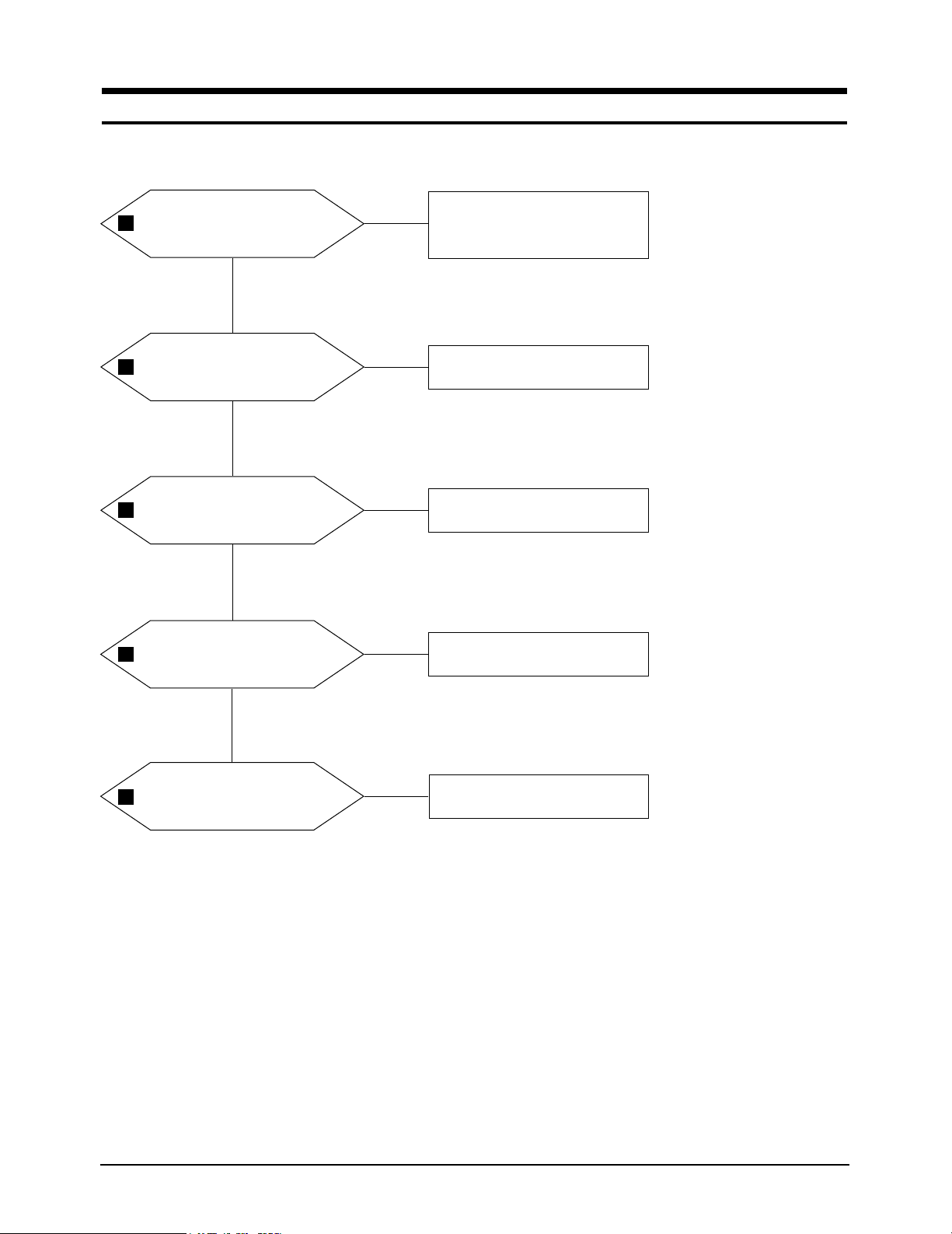
5 Troubleshooting
5-1 No Power
Does proper DC 14V/5V
appear at Pin 3. Pin 9 of
CN100?
Check CN803 Pin3, Pin9 in I/P
Board.
Yes
No
No
No
No
No
Does proper DC A5V
appear at FT144?
Check IC101 and IC105.
Yes
Does proper B3.3V
appear at Pin 2 of IC111?
Check IC111.
Yes
Does proper DC B1.8V
appear at Pin 4 of IC112?
Check IC112.
Yes
Does proper DC B8V
appear at FT130?
Check IC109.
1
2
3
4
5

5 Troubleshooting
5-2 LW17M24C/LW20M21C
No
No
No
Check IC704 and IC802.
Yes
Does proper DC 5V_P
appear
at Pin 2 of IC104?
Check IC104.
Yes
Does proper DC 9V_S
appear at FT127?
Check IC110.
Yes
Yes
Does proper DC B5V
appear at FT131?
Check IC108.
6
7
8

5 Troubleshooting
LW17M24C/LW20M21C 5-3
WAVEFORMS
1 2
5
3
6
44
7 8
 Loading...