

Samsung LW20M11C Service manual
TFT-LCD TV
Chassis Model
MU20EO LW20M11C
SERVICE
Manual
TFT-LCD TV CONTENTS
1. Precautions
2. Product Specifications
3. Disassembly & Reassembly
4. Alignment & Adjustments
5. Troubleshooting
6. Exploded View & Parts List
7. Electrical Parts List
8. Block Diagram
9. Wiring Diagram
10. PCB Layout
11. Schematic Diagrams
12. Panel Description
❈ This Service Manual is a property of Samsung
Electronics Co., Ltd.
Any unauthorized use of Manual can be punished
under applicable International and/or domestic law.
Samsung Electronics Co.,Ltd.
416, Maetan-3Dong, Paldal-Gu, Suwon City, Kyungki-Do, Korea, 442-742
Printed in Korea
P/N : BN82-00109F-00
URL : http://itself.sec.samsung.co.kr/
2 Product Specifications
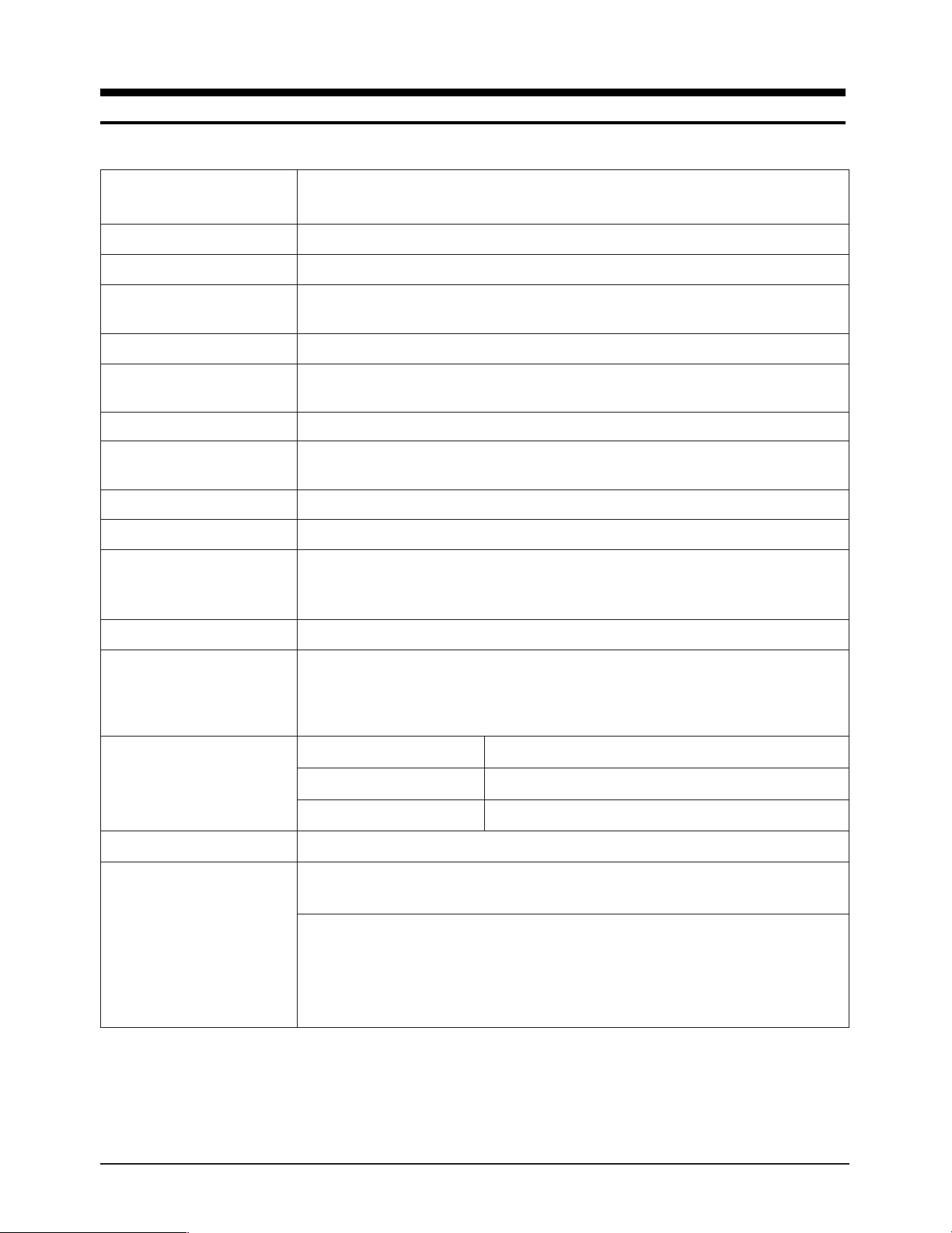
2-1 Specifications
Item
LCD Panel TFT-LCD panel, RGB vertical stripe, normaly
Display Colors 16.7 Million colors
Maximum Resolution Horizontal : 640 Pixels
Vertical : 480 Pixels
Input Video Signal Analog 0.7 Vp-p ± 5% positive at 75 Ω, internally terminated
Input Sync Signal Type : Seperate H/V
Level : TTL level
Maximum Pixel Clock rate 80 MHz
Active Display
Horizontal/Vertical
AC power voltage & Frequency
Power Consumption 65 W
Dimensions (W x D x H)
Set
Package 27.6 x 11.5 x 22.2 Inches (700 x 293 x 563 mm)
Weight (Set/Package) 9.81 Kg (21.62 Ibs) / 11.5 Kg (25.4 Ibs)
408 mm(H) / 306 mm(V)
AC 100 ~ 240 Volts, 50 Hz ~ 60 Hz
23.4 x 9.9 x 19.3 Inches (594 x 252 x 489.5 mm) / 23.4 x 3.5 x 16.8 Inches (594 x 90 x 427 mm)
Description
white, 20-Inch viewable, 0.64 mm pixel pitch
Environmental Considerations Operating Temperature : 50 °F ~ 104 °F (10 °C ~ 40 °C)
Operating Humidity : 10 % ~ 80 %
Storage Temperature : -4 °F ~ 113 °F (-20 °C ~ 45 °C)
Storage Humidity : 5 % ~ 95 %
Tunning Frequency Synthesize
TV System
Antena Input 75Ω, Coaxial Cable
– MAX Internal speaker Output : Right => 3W
Sound Characteristic
– BASS Control Range : -12 dB~ + 12 dB
– TREBLE Control Range : -12 dB~ + 12 dB
– Headphone Out: 5mW max (400m Vrms)
– Output Frequency : RF => 80 Hz ~ 15 kHz
System PAL / SECAM / NT 4.43-BG / DK / I
Sound STEREO
Left => 3W
A/V => 80 Hz ~ 15 kHz
LW20M11C 2-1
2 Product Specifications
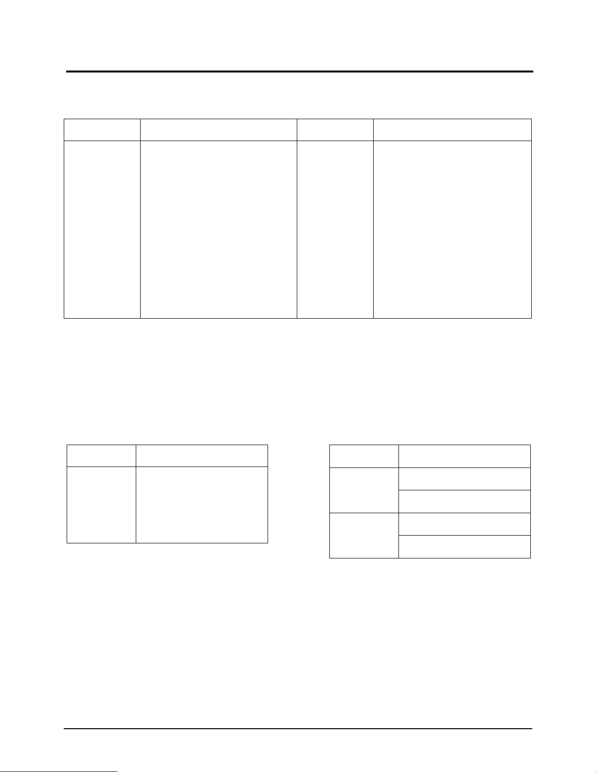
2-2 Pin Assignments
2-2-1 Scart
Pin No.
1
2
3
4
5
6
7
8
9
Items
Audio Out
Audio In
Audio Out
Audio Common GND
Blue GND
Audio In
Blue In
Function S/W
Green GND
Pin No.
10
11
12
13
14
15
16
17
18
Items
No Connection
Green In
No Connection
Red GND
F/B GND
Red In
RGB F/B
Video Output GND
Video Input GND
2-2-2 S-Video
Pin
1
2
3
4
5
Separate
GND
Y
C
GND
GND
2-2-3 A/V
RCA Yellow
RCA White
RCA Red
CVBS
Audio L
GND
Audio R
GND
2-2 LW20M11C
3 Disassembly and Reassembly
This section of the service manual describes the disassembly and reassembly procedures for the
LW20M11C TFT-LCD monitors.
WARNING: This monitor contains electrostatically sensitive devices. Use caution when handling
these components.
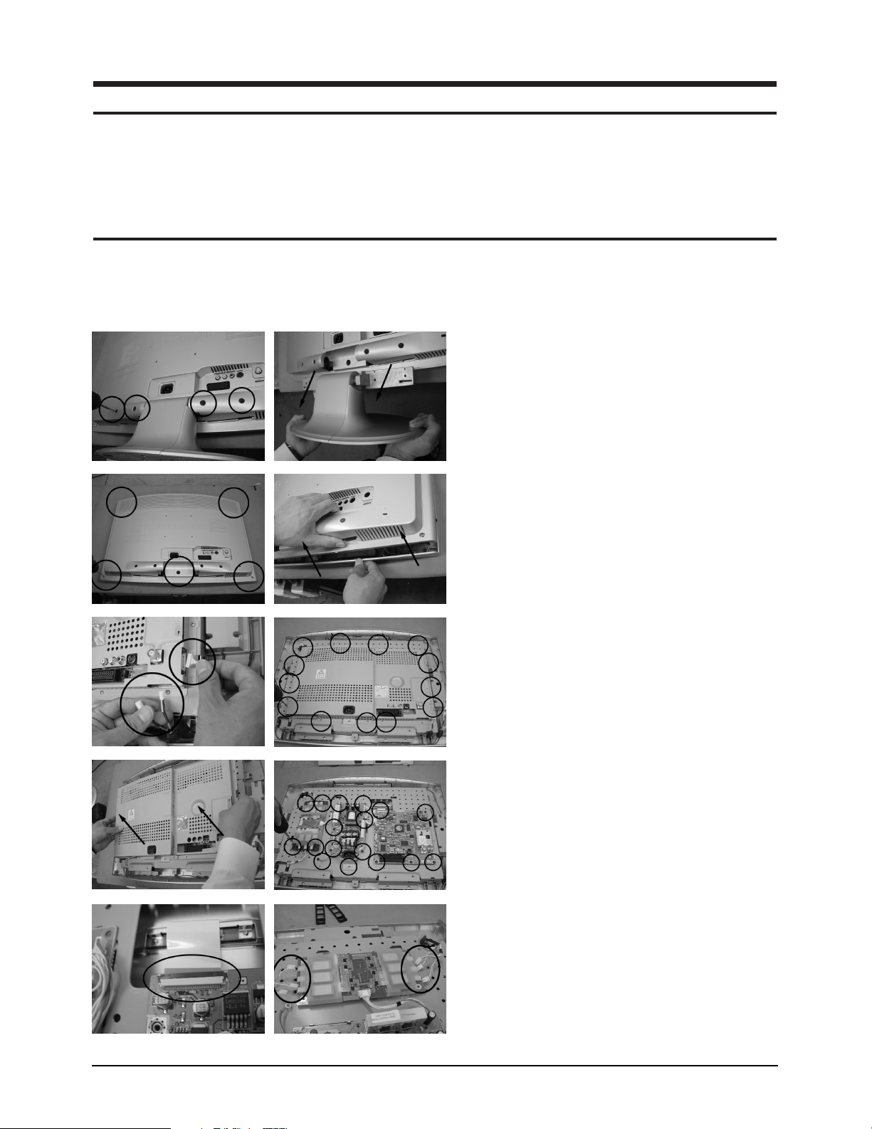
3-1 Disassembly
Cautions:1. Disconnect the monitor from the power source before disassembly.
2. Follow these directions carefully; never use metal instruments to pry apart the cabinet.
3. R/Cover opening jig : BH81-00001A
1. Place monitor face down on cushioned table.
Remove 4 screws from grip on the stand and
remove the stand.
2. Remove 5 screws from the back cover and
remove the back cover.
3. Disconnect speaker cable and IR cable from
the shield PCB. Remove 13 screws from the
shield PCB.
4. Lift up the shield PCB and remove 17 screws
from the MAIN boards.
5. Disconnect TTL cable and inverter cables from
the MAIN boards.
LW20M11C 3-1
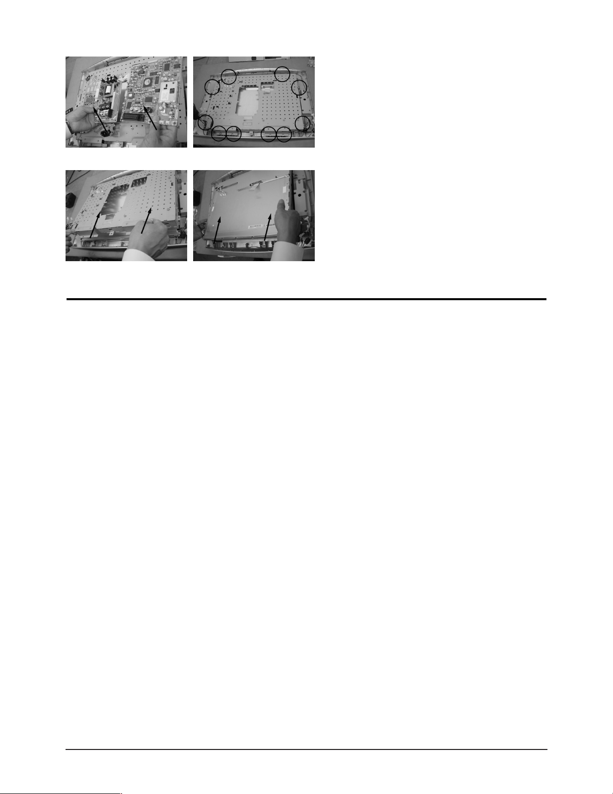
3 Disassembly and Reassembly
6. Lift up the boards and remove 10 screws form
the shield panel.
7. Remove the shield panel.
3-2 Reassembly
Reassembly procedures are in the reverse order of disassembly procedures.
❈ Inverter cable may be inserted to any connector on the monitor board for assemblin.
3-2 LW20M11C

4 Alignments and Adjustments
4-1 General Alignment Instuction
1. Usually, a color TV-VCR needs only slight touch-up adjustment upon installation.
Check the basic characteristics such as height, horizontal and vertical sync.
2. Use the specified test equipment or its equivalent.
3. Correct impedance matching is essential.
4. Avoid overload. Excessive signal from a sweep generator might overload the front-end of the TV.
When inserting signal markers, do not allow the marker generator to distort test result.
5. Connect the TV only to an DC power source with voltage and frequency as specified on
the backcover nameplate.
6. Do not attempt to connect or disconnect any wire while the TV is turned on.
Make sure that the power cord is disconnected before replacing any parts.
7. To protect aganist shock hazard, use an isolation transform.
LW20M11C 4-1
4 Alignments and Adjustments
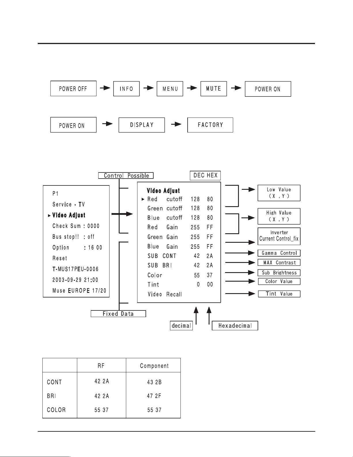
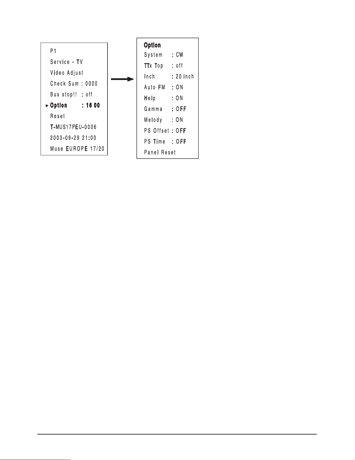
4-2 Factory Mode Adjustments
4-2-1 Entering Factory Mode
1. To enter “Service Mode” Press the remote -control keys in this sequence :
- If you do not have Factory remote - control
- If you have Factory remote - control
4-2-2 Factory Mode Tree
4-2 LW20M11C
4 Alignments and Adjustments
LW20M11C 4-3

4 Alignments and Adjustments
Memo
4-4 LW20M11C
5 Troubleshooting
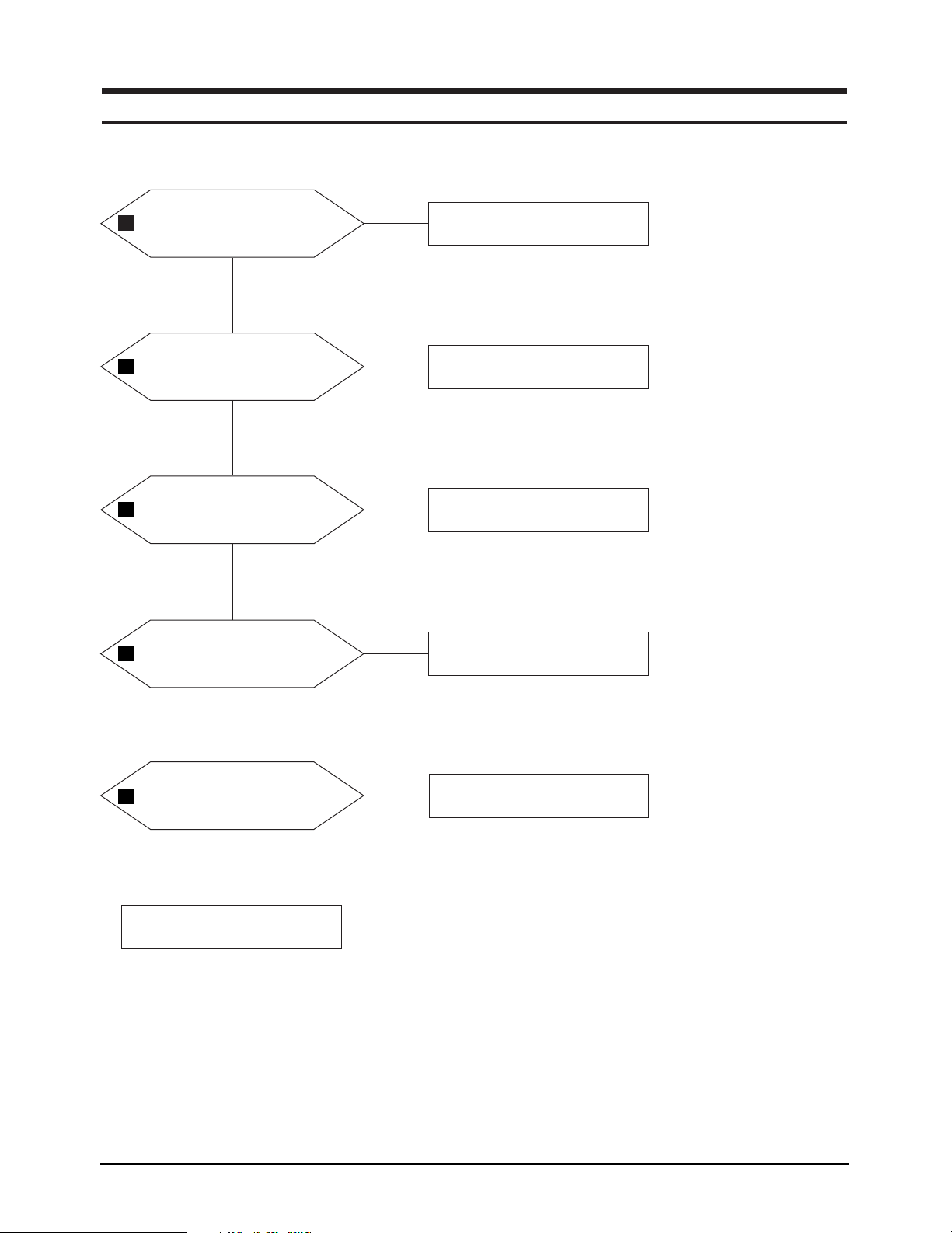
5-1 No Power
Does proper DC 14V/5V appear at
1
DC jack connected to CN120?
Yes
4
2
3
Does proper DC 5V
appear at Pin 2 of IC102?
Yes
Does proper DC 2.5V
appear at Pin 2 of IC106?
Yes
Does proper DC 14V
appear at Pin 5 of IC108?
No
Check FT101 and FT103.
No
Check IC103 and IC102.
No
Check IC106.
No
Check IC108.
Yes
1
LW20M11C 5-1
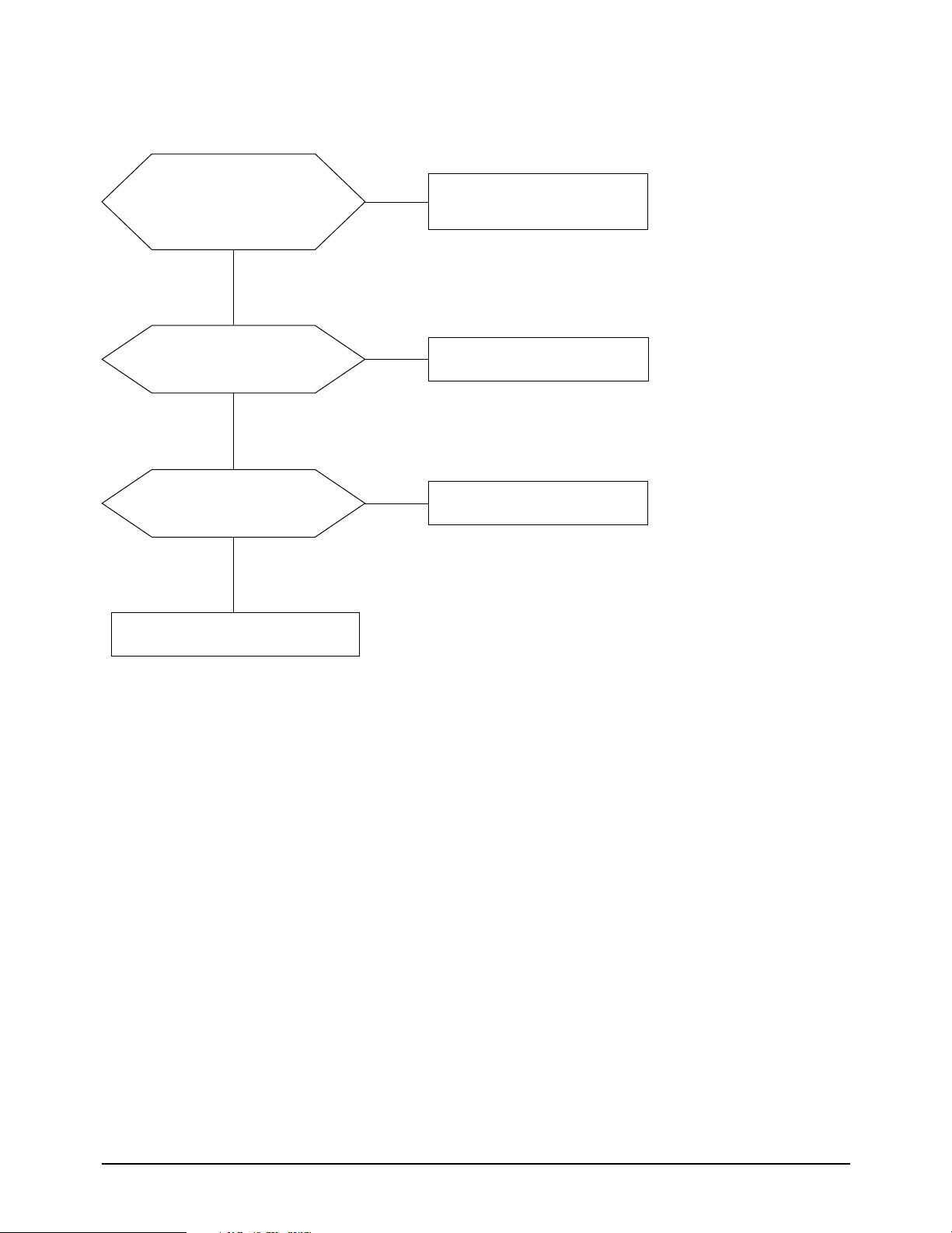
Does proper DC 5V
appear at FT107?
Yes
Check IC401.
No
Check IC108.

5 Troubleshooting
WAVEFORMS
1 2 3
4
5-2 LW20M11C

5-2 No Picture (TV, Video, S-Video, DVD)
5 Troubleshooting
Check C452 (TV)
5
Check C453 (Video)
Check C454 (S-Video)
Check C456 (DVD)?
Yes
Check the IC401.
No
Check the input signal.
WAVEFORMS
5
LW20M11C 5-3
5 Troubleshooting
5-3 No Sound
Does the signal appear at
Pin 67 (Tuner sound signal) and
Pin 53, 54 (Video sound) and
Pin 56, 57 (DVD Sound)
of IC501 (MSP3425)?
Yes
No
(RF) Check the Pin 8 of CN701.
(Video Sound) Check the CN903.
(DVD Sound) Check the CN905.
Does the signal appear at Pin 27,
28 of IC501 (MSP3425)?
Yes
Does the signal appear
at Pin16, 19, 2 and 5 of CN651?
Yes
Replace the speaker.
No
No
Check the Pin 3 of IC501 and
related circuit of IC501.
Check the IC651 (Audio amp)
and related circuit of IC651.
5-4 LW20M11C
 Loading...