

LCD-TV MONITOR
Chassis Model
ES15E* LW15E23CB
ES17E* LW17E24CB
Manual
SERVICE
LCD-TV MONITOR CONTENTS
1. Precautions
2. Product Specifications
3. Disassembly & Reassembly
4. Alignment & Adjustments
5. Troubleshooting
6. Exploded View & Parts List
7. Electrical Parts List
8. Block Diagram
9. Wiring Diagram
10. Schematic Diagrams
11. Panel Description
CONFIDENTIAL
1-1-1 Warnings
1. For continued safety, do not attempt to modify the
circuit board.
2. Disconnect the AC power and DC Power Jack
before servicing.
1-1-2 Servicing the LCD Monitor
1. When servicing the LCD Monitor disconnect the
AC line cord from the AC outlet.
2. It is essential that service technicians have an
accurate voltage meter available at all times. Check
the calibration of this meter periodically.
1-1-3 Fire and Shock Hazard
Before returning the monitor to the user, perform the
following safety checks:
1. Inspect each lead dress to make certain that the
leads are not pinched or that hardware is not
lodged between the chassis and other metal parts in
the monitor.
2. Inspect all protective devices such as nonmetallic
control knobs, insulating materials, cabinet backs,
adjustment and compartment covers or shields,
isolation resistor-capacitor networks, mechanical
insulators, etc.
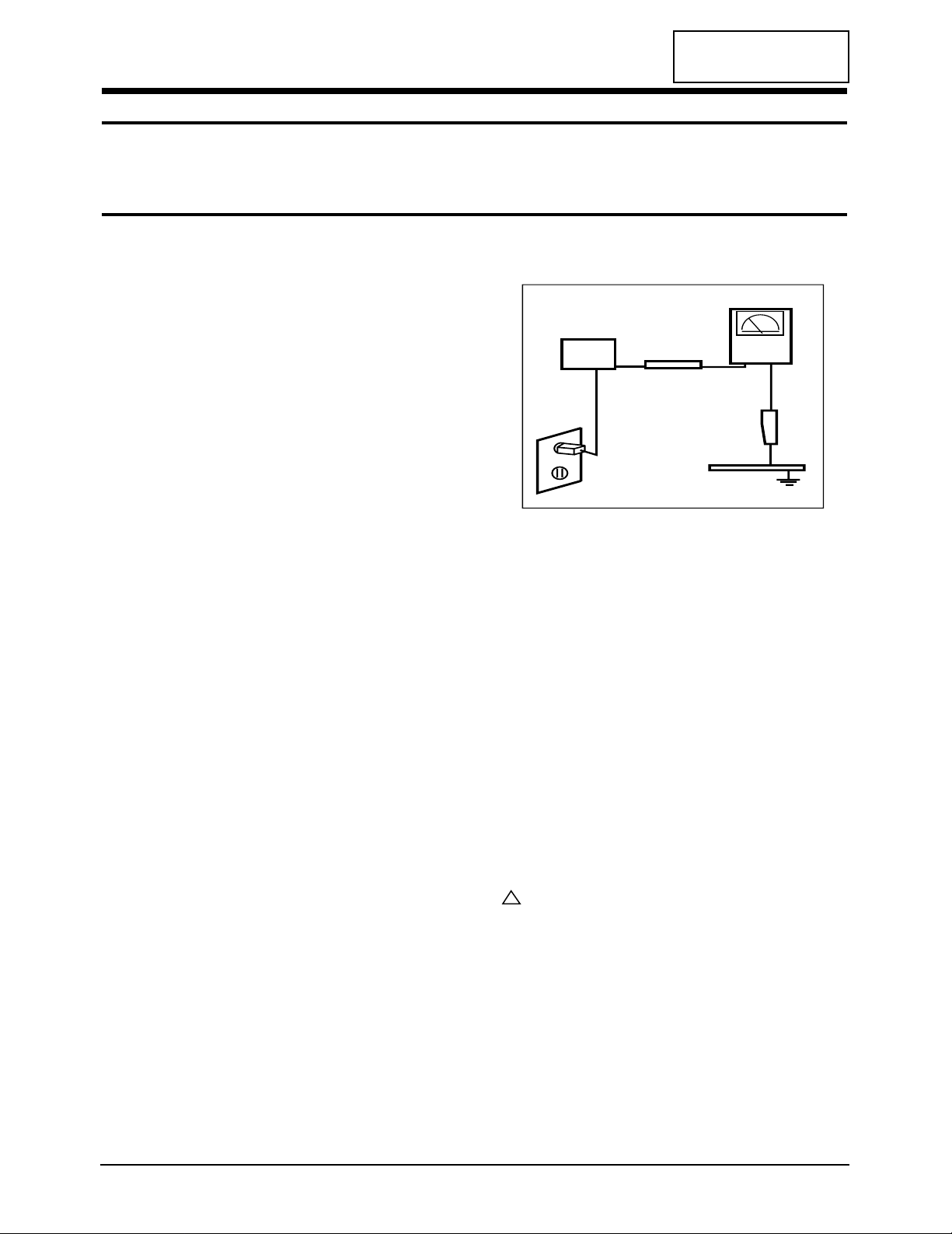
3. Leakage Current Hot Check (Figure 1-1):
WARNING: Do not use an isolation transformer during
this test.
Use a leakage current tester or a metering system
that complies with American National Standards
Institute (ANSI C101.1, Leakage Current for
Appliances), and Underwriters Laboratories (UL
Publication UL1410, 59.7).
Figure 1-1. Leakage Current Test Circuit
4. With the unit completely reassembled, plug the AC
line cord directly into a 120V AC outlet. With the
unit’s AC switch first in the ON position and then
OFF, measure the current between a known earth
ground (metal water pipe, conduit, etc.) and all
exposed metal parts, including: metal cabinets,
screwheads and control shafts. The current
measured should not exceed 0.5 milliamp. Reverse
the power-plug prongs in the AC outlet and repeat
the test.
1-1-4 Product Safety Notices
Some electrical and mechanical parts have special
safety-related characteristics which are often not
evident from visual inspection. The protection they give
may not be obtained by replacing them with
components rated for higher voltage, wattage, etc. Parts
that have special safety characteristics are identified by
on schematics and parts lists. A substitute
replacement that does not have the same safety
characteristics as the recommended replacement part
might create shock, fire and/or other hazards. Product
safety is under review continuously and new
instructions are issued whenever appropriate.
LW15E23CB/LW17E24CB 1-1
CONFIDENTIAL
1 Precautions
Follow these safety, servicing and ESD precautions to prevent damage and to protect against potential hazards such as
electrical shock.
1-1 Safety Precautions
DEVICE
UNDER
TEST
TEST ALL
EXPOSED METAL
SURFACES
(READING SHOULD
NOT BE ABOVE 0.5mA)
LEAKAGE
CURRENT
TESTER
2-WIRE CORD
ALSO TEST WITH
PLUG REVERSED
(USING AC ADAPTER
PLUG AS REQUIRED)
EARTH
GROUND
!
1-2-1 General Servicing Precautions
1. Always unplug the unit’s AC power cord from the
AC power source and disconnect the DC Power
Jack before attempting to:
(a) remove or reinstall any component or assembly,
(b) disconnect PCB plugs or connectors, (c) connect
a test component in parallel with an electrolytic
capacitor.
2. Some components are raised above the printed
circuit board for safety. An insulation tube or tape
is sometimes used. The internal wiring is
sometimes clamped to prevent contact with
thermally hot components. Reinstall all such
elements to their original position.
3. After servicing, always check that the screws,
components and wiring have been correctly
reinstalled. Make sure that the area around the
serviced part has not been damaged.
1. Immediately before handling any semiconductor
components or assemblies, drain the electrostatic
charge from your body by touching a known earth
ground. Alternatively, wear a discharging wriststrap device. To avoid a shock hazard, be sure to
remove the wrist strap before applying power to
the monitor.
2. After removing an ESD-equipped assembly, place it
on a conductive surface such as aluminum foil to
prevent accumulation of an electrostatic charge.
3. Do not use freon-propelled chemicals. These can
generate electrical charges sufficient to damage
ESDs.
4. Use only a grounded-tip soldering iron to solder or
desolder ESDs.
5. Use only an anti-static solder removal device. Some
solder removal devices not classified as “anti-static”
can generate electrical charges sufficient to damage
ESDs.
4. Check the insulation between the blades of the AC
plug and accessible conductive parts (examples:
metal panels, input terminals and earphone jacks).
5. Insulation Checking Procedure: Disconnect the
power cord from the AC source and turn the power
switch ON. Connect an insulation resistance meter
(500 V) to the blades of the AC plug.
The insulation resistance between each blade of the
AC plug and accessible conductive parts (see
above) should be greater than 1 megohm.
6. Always connect a test instrument’s ground lead to
the instrument chassis ground before connecting
the positive lead; always remove the instrument’s
ground lead last.
6. Do not remove a replacement ESD from its
protective package until you are ready to install it.
Most replacement ESDs are packaged with leads
that are electrically shorted together by conductive
foam, aluminum foil or other conductive materials.
7. Immediately before removing the protective
material from the leads of a replacement ESD,
touch the protective material to the chassis or
circuit assembly into which the device will be
installed.
Caution: Be sure no power is applied to the
chassis or circuit and observe all
other safety precautions.
8. Minimize body motions when handling
unpackaged replacement ESDs. Motions such as
brushing clothes together, or lifting your foot from
a carpeted floor can generate enough static
electricity to damage an ESD.
1 Precautions
1-2 LW15E23CB/LW17E24CB
CONFIDENTIAL
1-3 Electrostatically Sensitive Devices (ESD) Precautions
Some semiconductor (solid state) devices can be easily damaged by static electricity. Such components are commonly
called Electrostatically Sensitive Devices (ESD). Examples of typical ESD are integrated circuits and some field-effect
transistors. The following techniques will reduce the incidence of component damage caused by static electricity.
1-2 Servicing Precautions
WARNING: An electrolytic capacitor installed with the wrong polarity might explode.
Caution: Before servicing units covered by this service manual, read and follow the Safety Precautions
section of this manual.
Note: If unforeseen circumstances create conflict between the following servicing precautions and any of the
safety precautions, always follow the safety precautions.
Samsung Electronics Co.,Ltd.
416, Maetan-3Dong, Paldal-Gu, Suwon City, Kyungki-Do, Korea.
Printed in Korea
P/N : BN82-00071C-00
http://www.samsungmonitor.com (SyncMaster Worldwide)
http://www.samsung-monitor.com (SyncMaster USA)
http://www.sec.co.kr/monitor (Korea)
CONFIDENTIAL
2 Product Specifications
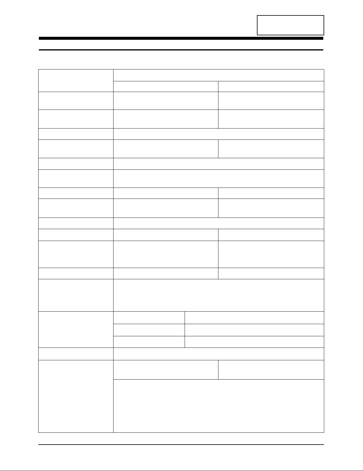
2-1 Specifications
LCD Panel TFT-LCD panel, RGB vertical stripe, normally TFT-LCD panel, RGB vertical stripe, normally
white, 15-Inch viewable, 0.297 mm pixel pitch white, 17-Inch viewable, 0.264 mm pixel pitch
Scanning Frequency Horizontal : 30 KHz ~ 69 KHz (Automatic) 30 KHz ~ 81 KHz (Automatic)
Vertical : 56 Hz ~ 75 Hz (Automatic) 56 Hz ~ 75 Hz (Automatic)
Display Colors 16.7 Million colors
Maximum Resolution Horizontal : 1024 Pixels 1280 Pixels
Vertical : 768 Pixels 1024 Pixels
Input Video Signal Analog 0.7 Vp-p ± 5% positive at 75 Ω, internally terminated
Input Sync Signal Type : Separate H/V, automatic synchronization without external switch of sync type
Level : TTL level
Maximum Pixel Clock rate 95 MHz 135 MHz
Active Display
Horizontal/Vertical
AC power voltage & Frequency
AC 90 ~ 264 Volts, 60 / 50 Hz ± 3 Hz
Power Consumption 48 W (Max), (2W Power surge) 58 W (Max), (2W Power surge)
Dimensions
Unit (W x D x H) 18.6 x 12.4 x 2.0 Inches (474 x 317 x 51 mm)
20.8 x 14.4 x 2.2 Inches (530 x 367 x 57 mm)
With stand (W x D x H)
18.6 x 15.6 x 8.0 Inches (474 x 397 x 204 mm)
20.8 x 17.6 x 8.0 Inches (530 x 447 x 204 mm)
Weight 3.97 Kg (8.75 Ibs) 4.95 Kg (10.9 Ibs)
Environmental Considerations Operating Temperature : 50 °F ~ 104 °F (10 °C ~ 40 °C)
Humidity : 10 % ~ 80 %
Storage Temperature : -13 °F ~ 113 °F (-25 °C ~ 45 °C)
Humidity : 5 % ~ 95 %
TV System
Antenna Input 75Ω, Coaxial Cable
– MAX internal speaker Out : Right => 3W Right => 5W
Left => 3W Left => 5W
Sound Characteristic
– BASS Control Range : -12dB~ + 12dB
– TREBLE Control Range : -12dB~ + 12dB
– Headphone Out: RF => 5mW max (400m Vrms)
A/V => 10mW max (580 Vrms), Max input sound: -9dBm
– Output Frequency : RF => 80 Hz ~ 15 KHz
A/V => 80 Hz ~ 20 KHz
LW15E23CB/LW17E24CB 2-1
Item
Description
LW15E23CB LW17E24CB
304.1 mm / 228.1 mm 338.1 mm / 270.1 mm
Tuning Frequency Synthesize
Color PAL Multi
Sound PAL Multi

CONFIDENTIAL
2 Product Specifications
2-2 LW15E23CB/LW17E24CB
2-2 Pin Assignments
Sync
Type
Pin No.
Separate H/V Composite H/V
Sync-on-green
1
2
3
4
5
6
7
8
9
10
11
12
13
14
15
Red
Green
Blue
GND
GND (DDC Return)
GND-Red
GND-Green
GND-Blue
No Connection
GND-Sync./Self Test
GND
DDC Data
Horizontal sync.
Vertical sync.
DDC Clock
Red
Green
Blue
GND
GND (DDC Return)
GND-Red
GND-Green
GND-Blue
No Connection
GND-Sync./Self Test
GND
DDC Data
H/V-Sync.
Not Used
DDC Clock
Red
Green + H/V Sync.
Blue
GND
GND (DDC Return)
GND-Red
GND-Green
GND-Blue
Not Used
GND-Sync./Self Test
GND
DDC Data
Not Used
Not Used
DDC Clock
CONFIDENTIAL
2 Product Specifications
LW15E23CB/LW17E24CB 2-3
QRS
P
O
Video
Sync
Sync
Horizontal
Vertical
CDE
P
O
B
A
Video
Sync
Sync
Separate Sync
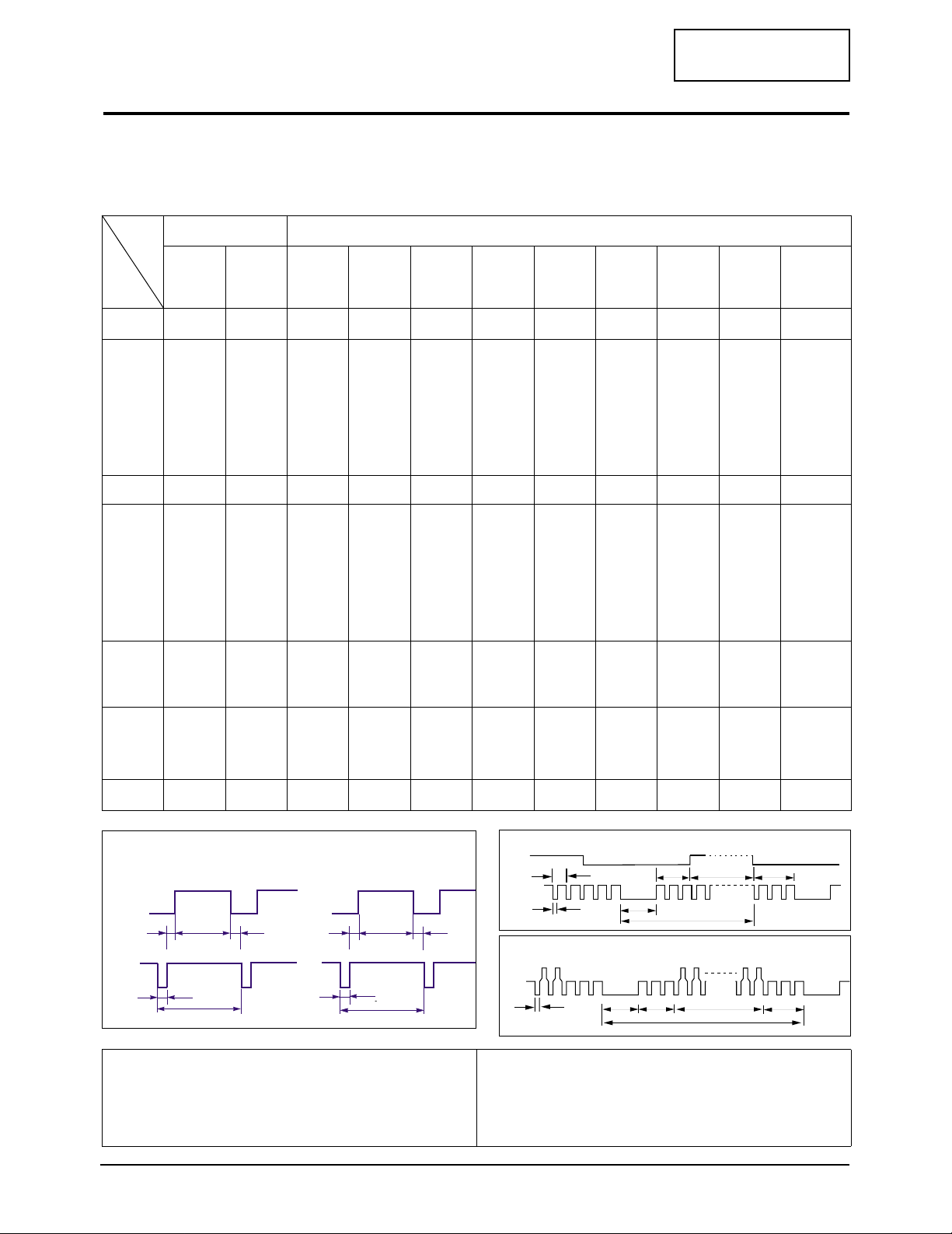
2-3 Timing Chart
This section of the service manual describes the timing that the computer industry recognizes as standard
for computer-generated video signals.
C D
A
O
E
B
P
Video
Sync
Sync
Video
Q R S
A : Line time total B : Horizontal sync width O : Frame time total P : Vertical sync width
C : Back porch D : Active time Q : Back porch R : Active time
E : Front porch S : Front porch
VIDEO
A
B
O
P
Q
R
S
Horizontal
Vertical
H/V Composite Sync
Sync-on-Green
79.976
12.504
1.067
1.837
9.481
0.119
75.025
13.329
0.038
0.475
12.804
0.013
135.000
Positive
Positive
Separate
81.129
16.640
6.400
2.880
3.200
76.106
10.660
0.080
3.200
0.020
135.000
Negative
Negative
Com.
68.677
14.561
1.016
2.201
10.836
0.508
84.997
11.765
0.044
0.524
11.183
0.015
94.500
Positive
Positive
Separate
1024/85Hz
1024x768
1280/76Hz
1280x1024
1280/75Hz
1280x1024
1024/75Hz
1024 x 768
60.023
16.660
1.219
2.235
13.003
0.203
75.029
13.328
0.050
0.466
12.795
0.017
78.750
Positive
Positive
Separate
31.469
31.777
3.813
1.589
26.058
0.318
70.087
14.268
0.064
0.858
13.155
0.191
28.322
Negative
Positive
Separate
fH (KHz)
A µsec
B µsec
C µsec
D µsec
E µsec
fV (Hz)
O msec
P msec
Q msec
R msec
S msec
Clock
Freq.
(MHz)
Polarity
H.Sync
V.Sync
Remark
IBM
640/75 Hz
640 x 480
640/85 Hz
640 x 480
800/75 Hz
800 x 600
800/85 Hz
800 x 600
1024/60Hz
1024 x 768
VGA2/
70 Hz
720 x 400
VGA3/
60 Hz
640 x 480
Table 2-1 Timing Chart
31.469
31.778
3.813
1.589
26.058
0.318
59.940
16.683
0.064
0.794
15.761
0.064
25.175
Negative
Negative
Separate
37.500
26.667
2.032
3.810
20.317
0.508
75.000
13.333
0.080
0.427
12.800
0.027
31.500
Negative
Negative
Separate
43.269
23.111
1.556
2.222
17.778
1.556
85.008
11.764
0.671
0.578
11.093
0.023
49.500
Negative
Negative
Separate
46.875
21.333
1.616
3.232
16.162
0.323
75.000
13.333
0.064
0.448
12.800
0.021
49.500
Positive
Positive
Separate
53.674
18.631
1.138
2.702
14.222
0.569
85.061
11.756
0.056
0.503
11.179
0.019
56.250
Positive
Positive
Separate
48.363
20.677
2.092
2.462
15.754
0.369
60.004
16.666
0.124
0.600
15.880
0.062
75.000
Negative
Negative
Separate
Mode
VESA
Timing
(17” Only) (17” Only)
Green
Horizontal
Vertical
P
B
Q
R
O
S

Memo
2 Product Specifications
2-4 LW15E23CB/LW17E24CB
CONFIDENTIAL
LW15E23CB/LW17E24CB 3-1
CONFIDENTIAL
3 Disassembly and Reassembly
This section of the service manual describes the disassembly and reassembly procedures for the
LW15E23CB/LW17E24CB monitor.
WARNING: This monitor contains electrostatically sensitive devices. Use caution when handling
these components.
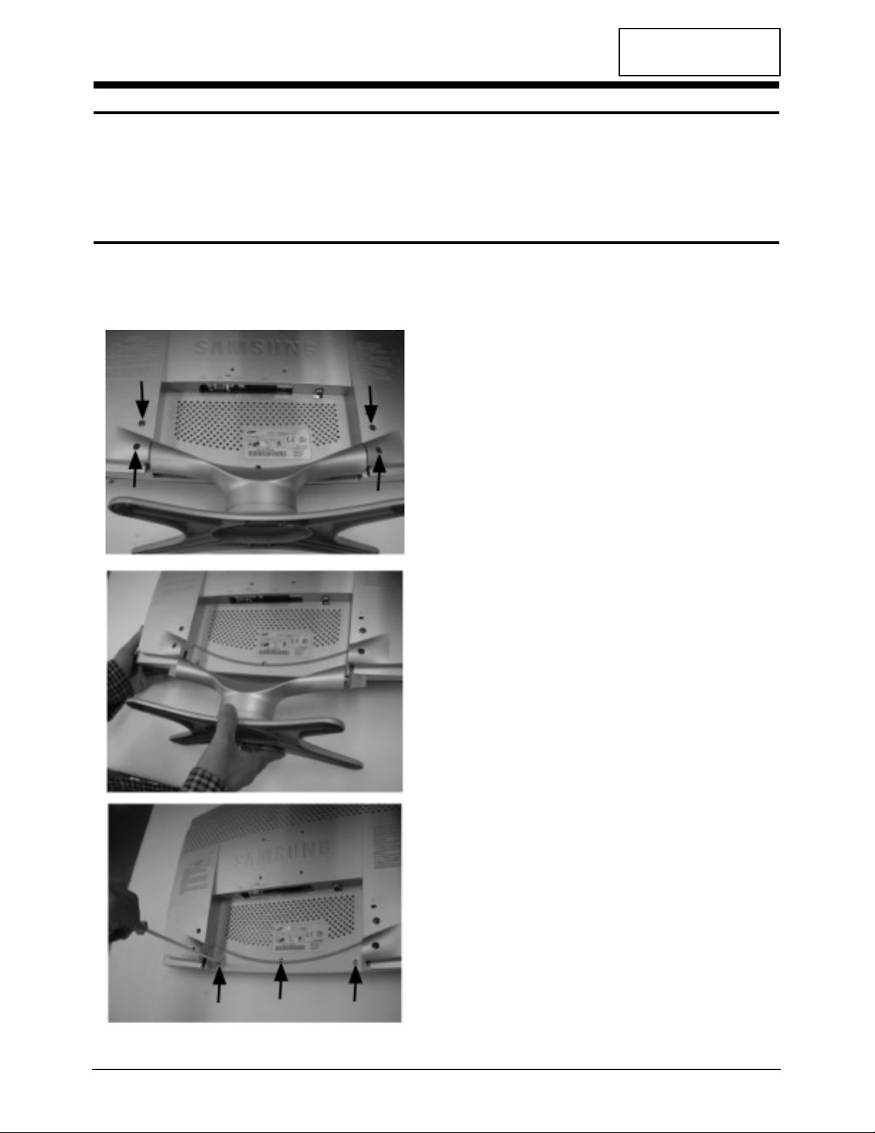
3-1 Disassembly
Cautions:1. Disconnect the monitor from the power source before disassembly.
2. Follow these directions carefully; never use metal instruments to pry apart the cabinet.
1. Remove the 4 screws (Rear Cover + Stand) on
the rear cover.
2. Remove the assy stand from rear cover.
3. Remove the 3 screws (Rear Cover + Cover
Front) on the rear.
CONFIDENTIAL
3 Disassembly and Reassembly
3-2 LW15E23CB/LW17E24CB
3-2 Reassembly
Reassembly procedures are in the reverse order of dissasembly procedures.
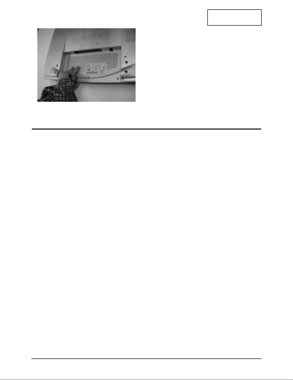
4. Lift up the rear cover until it opens
completely.
CONFIDENTIAL
LW15E23CB/LW17E24CB 4-1
4 Alignments and Adjustments
4-1 General Alignment Instruction
1. Usually, a color TV-VCR needs only slight touch-up adjustment upon installation.
Check the basic characteristics such as height, horizontal and vertical sync.
2. Use the specified test equipment or its equivalent.
3. Correct impedance matching is essential.
4. Avoid overload. Excessive signal from a sweep generator might overload the front-end
of the TV. When inserting signal markers, do not allow the marker generator to distort
test results.
5. Connect the TV only to an DC power source with voltage and frequency as specified on
the backcover nameplate.
6. Do not attempt to connect or disconnect any wire while the TV is turned on. Make sure
that the power cord is disconnected before replacing any parts.
7. To protect aganist shock hazard, use an isolation transformer.
4 Alignments and Adjustments
4-2 LW15E23CB/LW17E24CB
CONFIDENTIAL
4-2 Adjustment Instruction
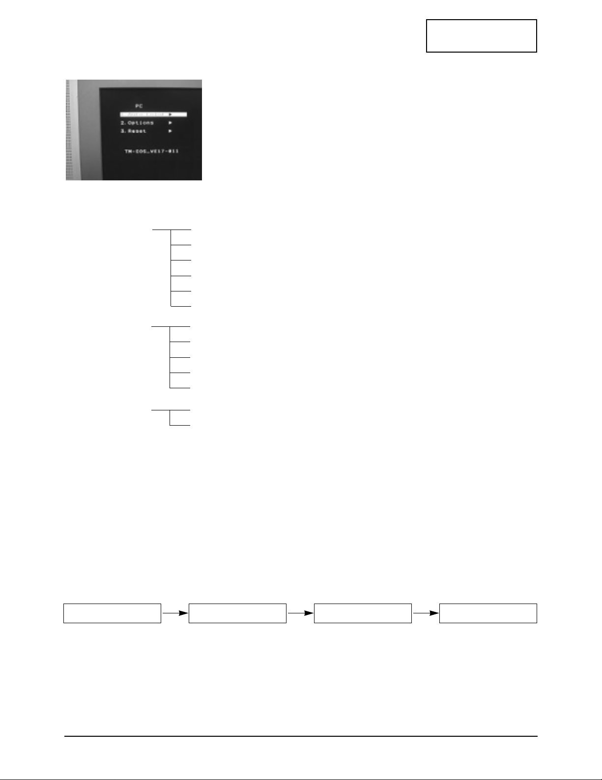
4-2-1 Service Mode Screen
1. Adjustment
2. Options
3. Auto Color
4. Reset
4-2-2 Service function
1. EEPROM Clear : Initially executed when replacing OTP.
2. TV Auto Color : Used to adjust TV image color.
3. PC Auto Color : Used to adjust PC image color.
4. Reset : Used after all adjustments.
5. Other functions shown are not service related.
4-2-3 Adjustment Sequence for ROM change only
RGB Contrast
RGB Bright
R Gain
G Gain
B Gain
FB Gain
Default : on
Help Osd : off
Suwon Ch Table
Spain Ch Table
Eeprom clear
Auto color (PC)
Auto color (TV)
EEPROM Clear TV auto color PC auto color RESET
(For ROM
change only)
CONFIDENTIAL
LW15E23CB/LW17E24CB 5-1
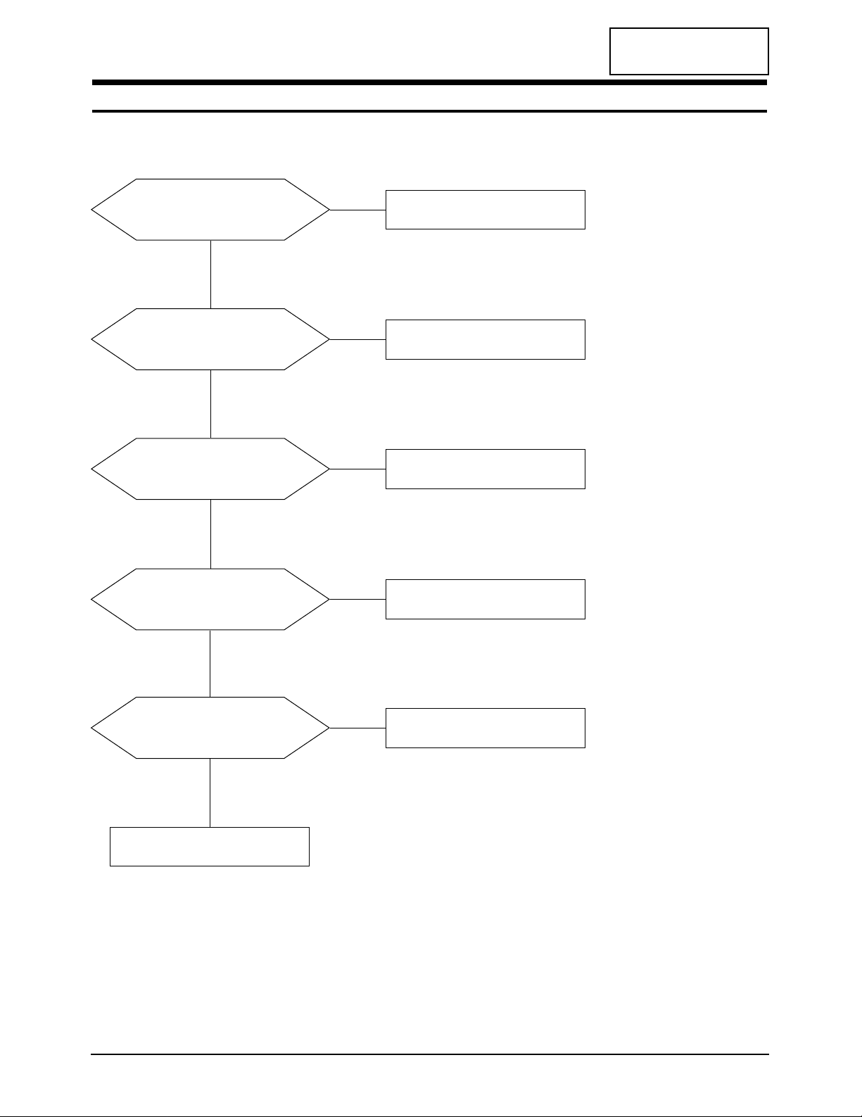
5 Troubleshooting
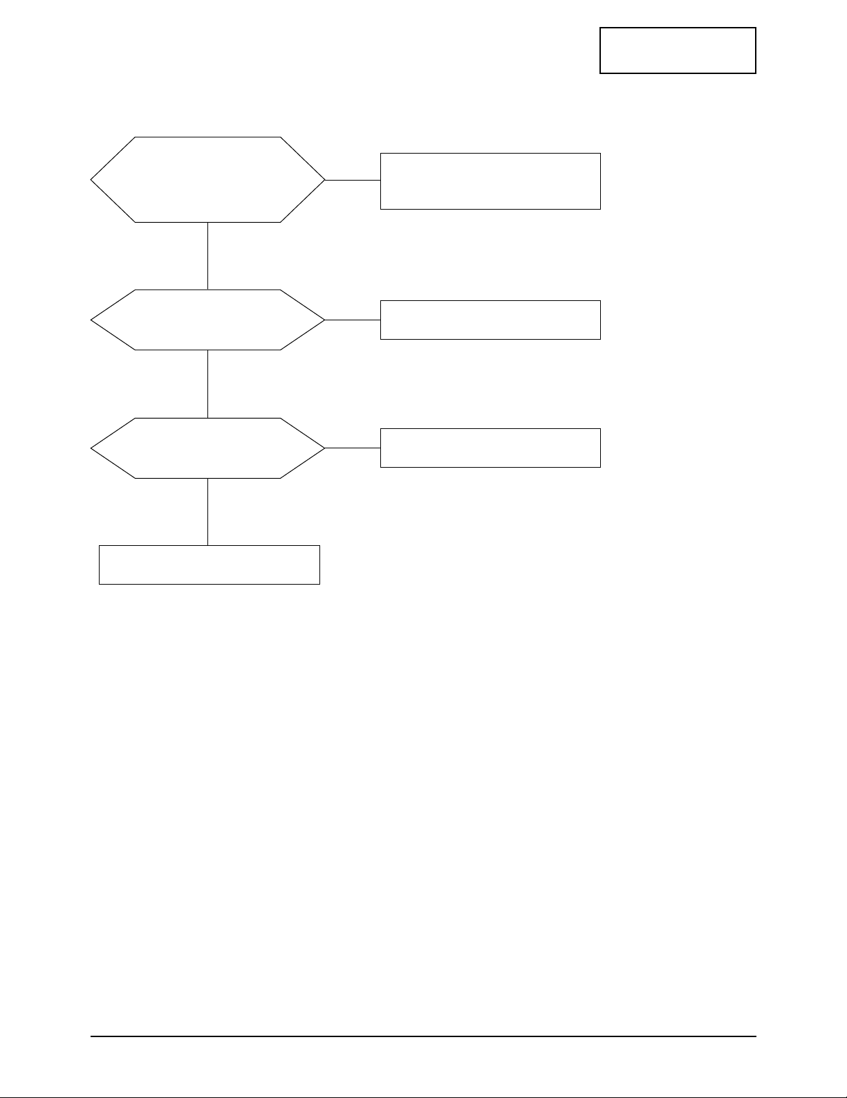
5-1 No Power
Does proper DC 14 V appear at
DC jack connected to CN12?
Check SMPS PCB and Adapter.
Yes
No
Does proper DC 5 V appear at
Pin 4 of IC11?
Check IC11.
Check IC23.
Yes
No
Does proper DC 14V appear at
Pin 1 of IC11?
Check IC11.
Yes
No
Does proper DC 3.3 V appear at
Pin 3 of IC14?
Check IC14.
Yes
Yes
No
Does proper DC 2.5 V appear at
Pin 4 of IC109 and IC17?
Check IC109 and IC17.
No
CONFIDENTIAL
5 Troubleshooting
5-2 LW15E23CB/LW17E24CB
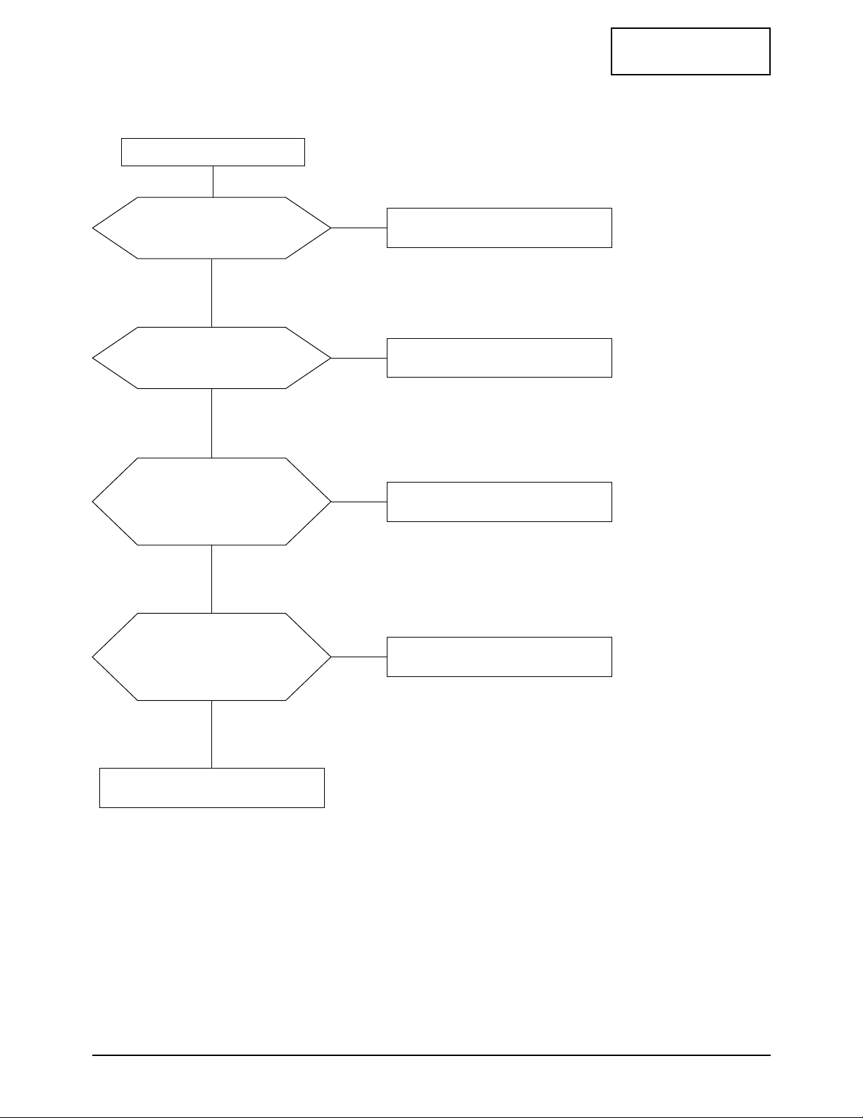
5-2 No Video (PC Signal)
Power indicator is green.
Does the signal appear
at C134, C135, C136
of R, G, B input?
Check CN11.
Yes
Yes
No
Does the clock pulse
appear at X21?
Check X21 and related circuit of X21.
Yes
No
Does the clock pulse appear at
output of <RA35~RA39, RA310>15”
<RA35~RA39, RA310,
RA313~318>17”?
Check related circuit of IC32.
Yes
No
Does the clock pulse appear at
output of <R611~R620>15”
<R611~R620, R61~R69, R610>17”?
Replace
<R611~R620>15”
<R611~R620, R61~R69, R610>17”.
Yes
No
Replace LCD Panel.

CONFIDENTIAL
5 Troubleshooting
LW15E23CB/LW17E24CB 5-3
Does signal appear at
<RA35~RA39, RA310>15”
<RA35~RA39, RA310, RA313~RA318>17”
of related IC32?
Check IC32 and related circuit .
Yes
No
Check IC61, 62 and
<R611, 612, ~R620>15”
<R611, 612, ~R620, R61~R69, R610>17”.
5-3 No Picture (TV, Video, S-Video)
Check Pin 55, 56 (S-Video) and
Pin 52 (VCR) and Pin 74 and Pin 53
(RF-CVBS) and Pin 58 (Scart-Vin)
of IC401 (VSP9407)?
Check CN41 (Tuner) and
CN26 (VCR connector).
Yes
No
Does the signal appear at
RA33, RA34, RA311, RA312?
Check IC401 (VSP9407)
and related circuit.
Yes
No
CONFIDENTIAL
5 Troubleshooting
5-4 LW15E23CB/LW17E24CB
Does the signal appear at
Pin 67 (Tuner sound signal) and
Pin 57, 56 (PC sound) and Pin 51, 50
(VCR sound) of IC53 (MSP3421G)?
Check CN11 (PC conector)
and CN26(VCR connector).
Yes
No
Does the signal appear at Pin 27,
28 of IC53 (MSP3421G)?
Check IC32 and related circuit.
Yes
No
Does the signal appear
at L53~L56?
Check IC55 (Audio amp) and related circuit.
Yes
No
Replace the speaker.
5-4 No Sound

CONFIDENTIAL
LW15E23CB/LW17E24CB 6-1
6 Exploded View and Parts List
6-1-1 LW15E23CB

6 Exploded View & Parts List
6-2 LW15E23CB/LW17E24CB
CONFIDENTIAL
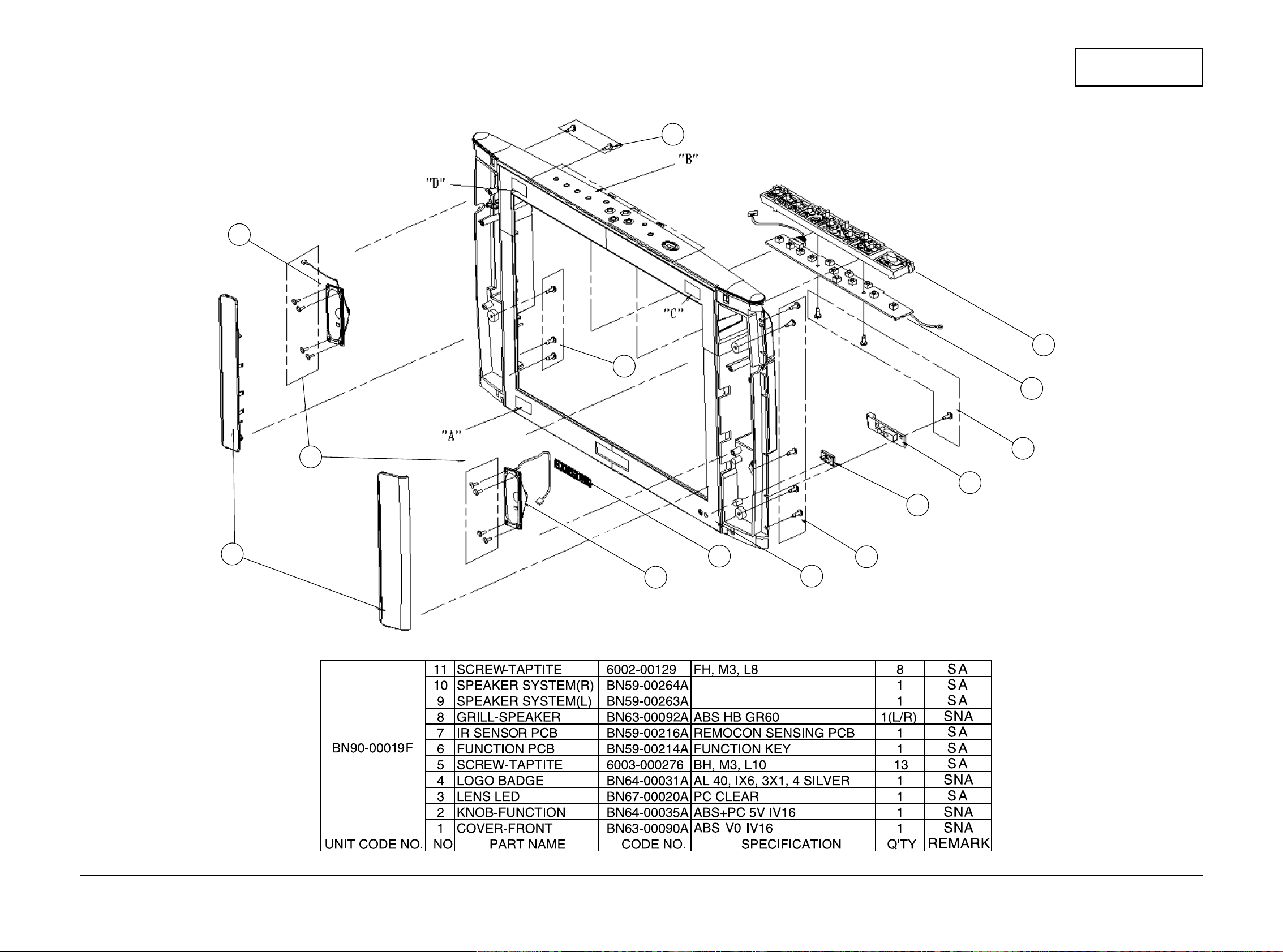
6-1-2 LW15E23CB Front
11
10
8
9
4
1
5
3
7
5
6
2
5
5
LW15E23CB/LW17E24CB 6-3
6 Schematic Diagrams
CONFIDENTIAL
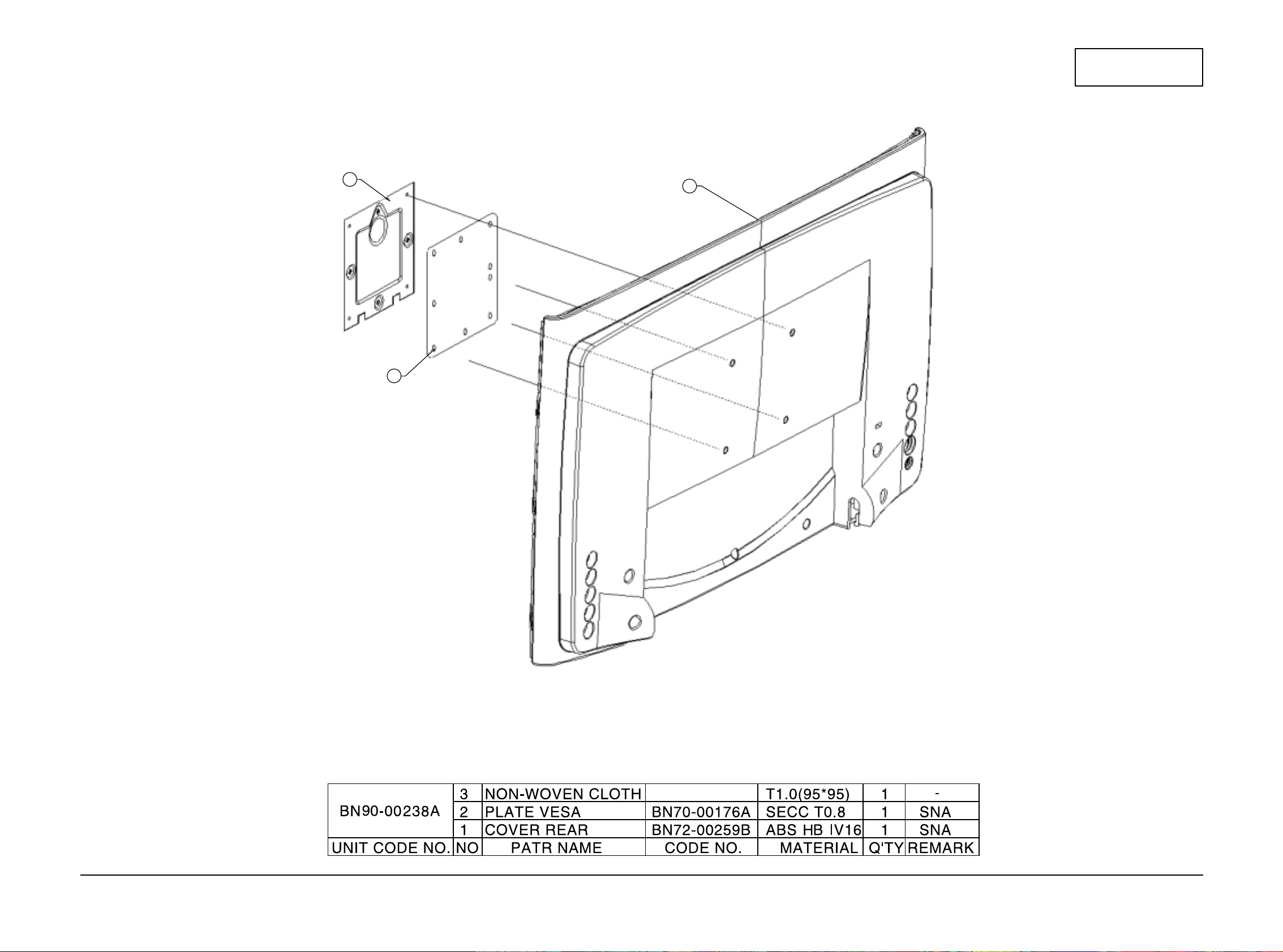
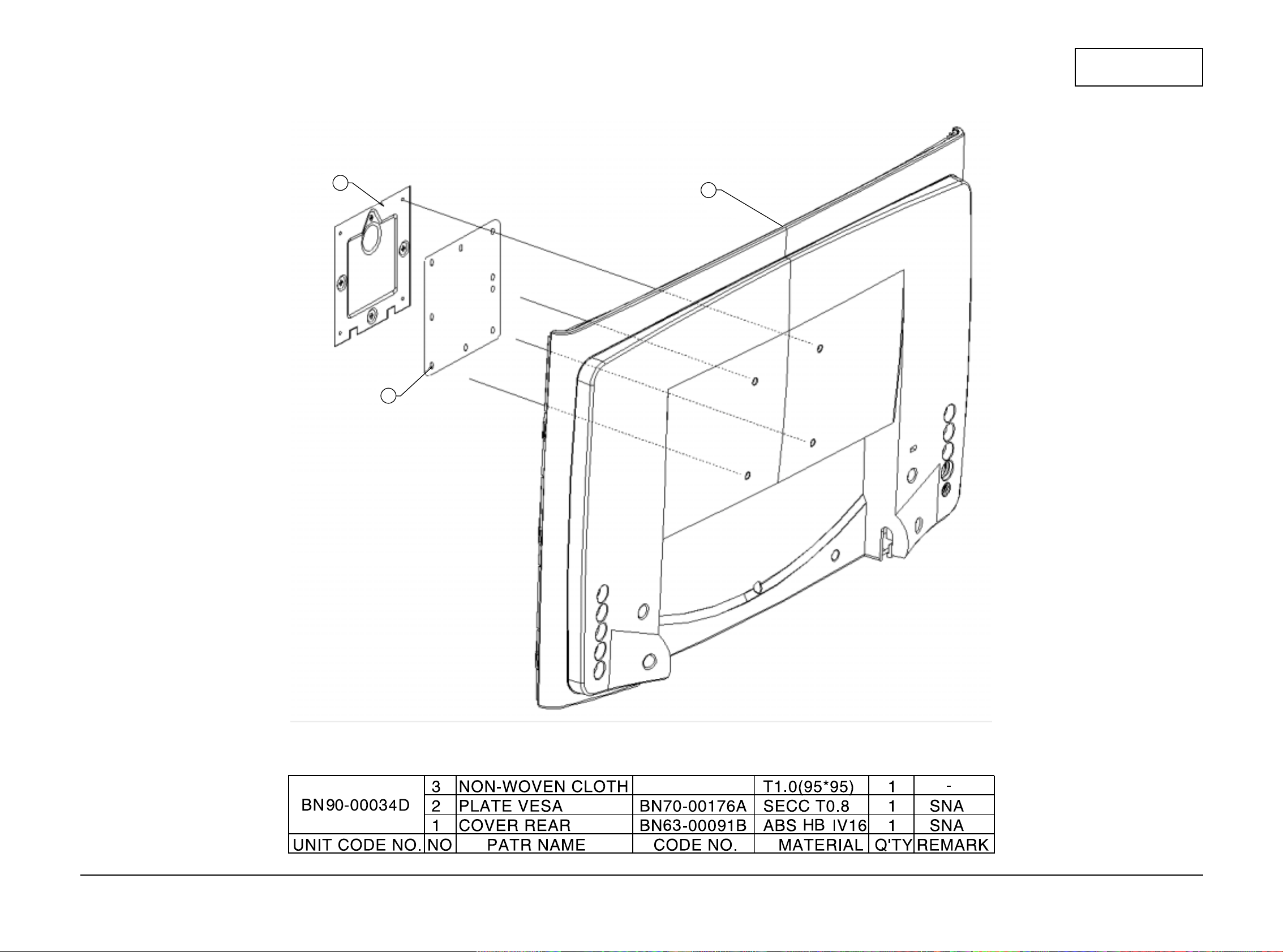
6-1-3 LW15E23CB Rear
2
3
1
6 Exploded View & Parts List
6-4 LW15E23CB/LW17E24CB
CONFIDENTIAL
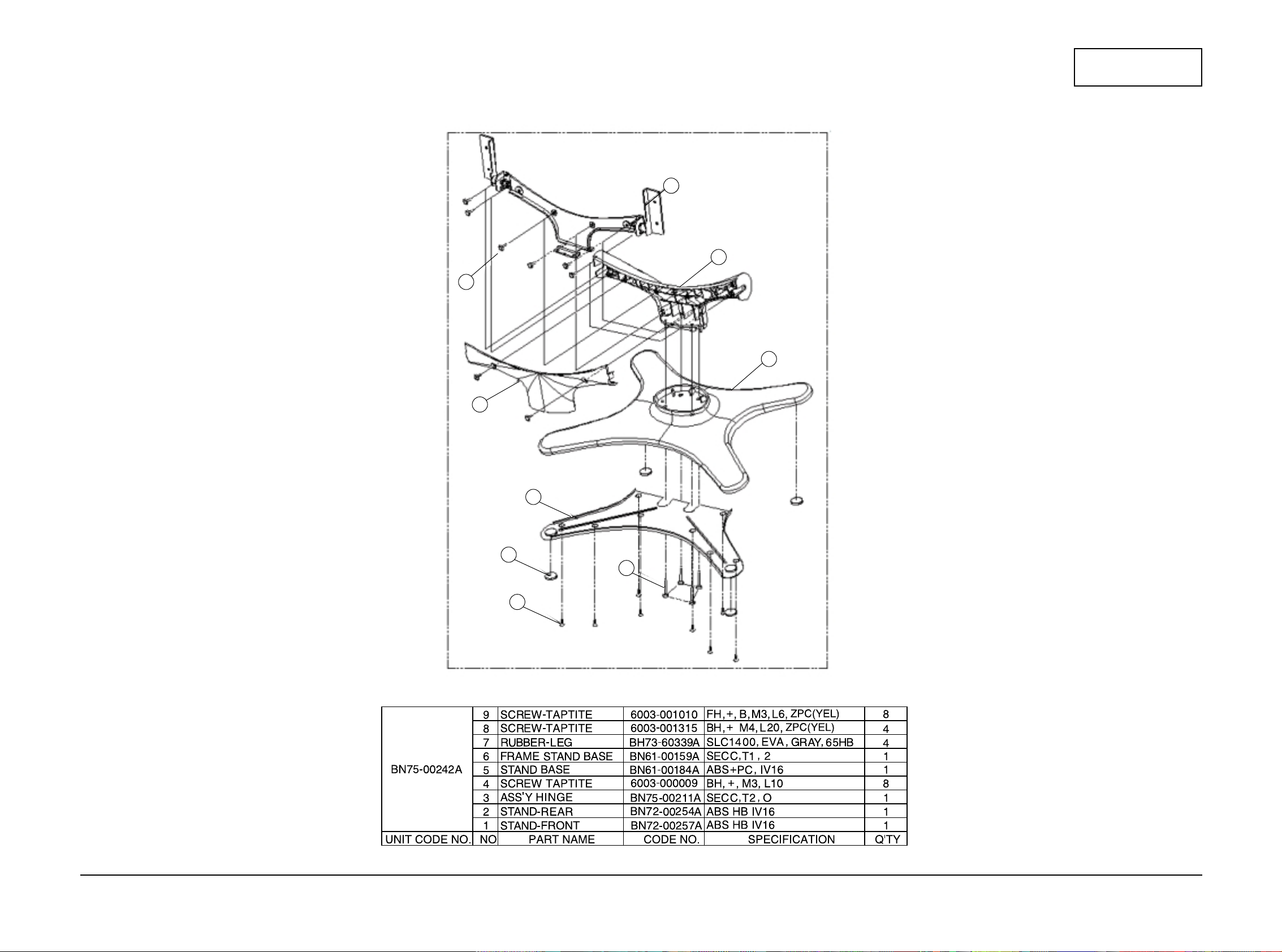
6-1-3 LW15E23CB Stand
3
2
5
4
1
6
8
7
9

LW15E23CB/LW17E24CB 6-5
6 Schematic Diagrams
CONFIDENTIAL
6-2-1 LW17E24CB
6 Exploded View & Parts List
6-6 LW15E23CB/LW17E24CB
CONFIDENTIAL
6-2-2 LW17E24CB Front
11
10
8
9
4
1
5
3
7
5
6
2
5
5
LW15E23CB/LW17E24CB 6-7
6 Schematic Diagrams
CONFIDENTIAL
6-2-3 LW17E24CB Rear
2
3
1
 Loading...