

1_LW15E13C-Ecover Page 1 Friday, July 20, 2001 3:41 PM
LW15E13C/LW17E14C
(For PAL systems)
TFT-LCD TV/Monitor
Owner’s
Instructions
•
•
1_Ecov2 Page 1 Friday, July 20, 2001 3:42 PM
1. Adjust computer resolution and screen injection rate (refresh rate) in control panel of
computer as described below to enjoy the best quality of picture. You can have an uneven
quality of picture in the screen if the best quality of picture is not provided in TFT-LCD.
Resolution: 15” 1024 x 768 • Vertical frequency (refresh rate): 60 Hz
17” 1280 x 1024
2. TFT LCD panel manufactured by using advanced semiconductor technology with precision
of 99.999% above is used for this product. But the pixels of RED, GREEN, BLUE and
WHITE color seem to be bright sometimes or some of black pixels could be seen. This is
not from bad quality and you can use it without uneasiness.
For example, the no. of TFT LCD pixels that is contained in this product are
FrançaisDeutschEspañolPortuguese EnglishItaliano
2,359,296 (15”), 3,932,160 (17”).
3. When you clean the monitor and the panel outside, please apply the recommended small
amount of cleaner by using soft and dry cloth and polish it. Let LCD area not to be forced
but to be scrubbed out softly. If excessive force is applied, you can have a stain on it.
4. If you are not satisfied with the quality of picture, you can get better quality of picture by
executing "auto adjustment function" in display screen that is appeared as window
termination button is pressed. If there's still noise after automatic adjustment, use FINE/
COARSE adjustment function.
Information in this document is subject to change without notice.
© 2001 Samsung Electronics Co., Ltd. All rights reserved.
Reproduction in any manner whatsoever without the written permission of Samsung Electronics Co.,
Ltd. is strictly forbidden.
Samsung Electronics Co., Ltd. shall not be liable for errors contained herein or for incidental or
consequential damages in connection with the furnishing, performance, or use of this material.
The
Samsung logo
are registered trademarks of Video Electronics Standard Association; the
are registered trademarks of the U.S. Environmental Protection Agency (EPA). As an E
Partner, Samsung Electronics Co., Ltd. has determined that this product meets the E
guidelines for energy efficiency. All other product names mentioned herein may be the trademarks or
registered trademarks of their respective owners.
is the registered trademark of Samsung Electronics Co., Ltd.;
E
NERGY
VESA, DPMS
S
name and logo
TAR
NERGY
NERGY
S
S
TAR
and
TAR
DDC
2_LW15E13C-TOC.fm Page 1 Friday, July 20, 2001 3:43 PM
Table of Contents
Safety Instructions. . . . . . . . . . . . . . . . . . . . . . . . . . . . . . . . . . . . . . . . . . . . . . . . . . . . . . . . . . . 2
Unpacking Your TV/Monitor . . . . . . . . . . . . . . . . . . . . . . . . . . . . . . . . . . . . . . . . . . . . . . . . . . . 3
Setting up Your LCD TV/Monitor . . . . . . . . . . . . . . . . . . . . . . . . . . . . . . . . . . . . . . . . . . . . . . 4
Setting up an Ergonomic Workstation . . . . . . . . . . . . . . . . . . . . . . . . . . . . . . . . . . . . . . . 4
TV/Monitor Location . . . . . . . . . . . . . . . . . . . . . . . . . . . . . . . . . . . . . . . . . . . . . . . . . 4
Workstation Height . . . . . . . . . . . . . . . . . . . . . . . . . . . . . . . . . . . . . . . . . . . . . . . . . . 4
Viewing Angle . . . . . . . . . . . . . . . . . . . . . . . . . . . . . . . . . . . . . . . . . . . . . . . . . . . . . . 4
Connecting Your LCD TV/Monitor . . . . . . . . . . . . . . . . . . . . . . . . . . . . . . . . . . . . . . . . . 5
Connecting TV Tuner Box . . . . . . . . . . . . . . . . . . . . . . . . . . . . . . . . . . . . . . . . . . . . . . . . 6
Plug and Play . . . . . . . . . . . . . . . . . . . . . . . . . . . . . . . . . . . . . . . . . . . . . . . . . . . . . . . . . . 7
Installing the Video Driver . . . . . . . . . . . . . . . . . . . . . . . . . . . . . . . . . . . . . . . . . . . . . . . . 7
Self-Test Feature Check (STFC) . . . . . . . . . . . . . . . . . . . . . . . . . . . . . . . . . . . . . . . . . . . . . . 7
Getting Help . . . . . . . . . . . . . . . . . . . . . . . . . . . . . . . . . . . . . . . . . . . . . . . . . . . . . . . . . . 8
Warm-up Time . . . . . . . . . . . . . . . . . . . . . . . . . . . . . . . . . . . . . . . . . . . . . . . . . . . . . . . . . 8
Adjusting Your LCD TV/Monitor . . . . . . . . . . . . . . . . . . . . . . . . . . . . . . . . . . . . . . . . . . . . . . . 9
User Controls . . . . . . . . . . . . . . . . . . . . . . . . . . . . . . . . . . . . . . . . . . . . . . . . . . . . . . . . . . 9
Automatic Save . . . . . . . . . . . . . . . . . . . . . . . . . . . . . . . . . . . . . . . . . . . . . . . . . . . . . . . . . 10
Direct-Access Features . . . . . . . . . . . . . . . . . . . . . . . . . . . . . . . . . . . . . . . . . . . . . . . . . 11
OSD Lock/Unlock. . . . . . . . . . . . . . . . . . . . . . . . . . . . . . . . . . . . . . . . . . . . . . . . . . . . . 11
On Screen Display (OSD). . . . . . . . . . . . . . . . . . . . . . . . . . . . . . . . . . . . . . . . . . . . . . . . . . 12
Accessing the Menu System . . . . . . . . . . . . . . . . . . . . . . . . . . . . . . . . . . . . . . . . . . . 12
OSD Functions and Adjustments . . . . . . . . . . . . . . . . . . . . . . . . . . . . . . . . . . . . . . 13
PC Functions and Adjustments . . . . . . . . . . . . . . . . . . . . . . . . . . . . . . . . . . . . . . . . 14
TV/ Video Functions and Adjustments . . . . . . . . . . . . . . . . . . . . . . . . . . . . . . . . . . 18
Appendix . . . . . . . . . . . . . . . . . . . . . . . . . . . . . . . . . . . . . . . . . . . . . . . . . . . . . . . . . . . . . . . . 22
By Remote-Control . . . . . . . . . . . . . . . . . . . . . . . . . . . . . . . . . . . . . . . . . . . . . . . . . . . . . 22
PowerSaver . . . . . . . . . . . . . . . . . . . . . . . . . . . . . . . . . . . . . . . . . . . . . . . . . . . . . . . . . . . .24
Troubleshooting . . . . . . . . . . . . . . . . . . . . . . . . . . . . . . . . . . . . . . . . . . . . . . . . . . . . . . . 25
Specifications . . . . . . . . . . . . . . . . . . . . . . . . . . . . . . . . . . . . . . . . . . . . . . . . . . . . . . . . 28
Pin Assignments . . . . . . . . . . . . . . . . . . . . . . . . . . . . . . . . . . . . . . . . . . . . . . . . . . . . . . . 30
Display Modes. . . . . . . . . . . . . . . . . . . . . . . . . . . . . . . . . . . . . . . . . . . . . . . . . . . . . . . . . .31
Attaching a Wall or Arm Mounting Device. . . . . . . . . . . . . . . . . . . . . . . . . . . . . . . . . . . . 33
Installing VESA Compliant Mounting Devices . . . . . . . . . . . . . . . . . . . . . . . . . . . . . . . . 34
Wall Mount Instructions . . . . . . . . . . . . . . . . . . . . . . . . . . . . . . . . . . . . . . . . . . . . . . . 34
Retractable Stand . . . . . . . . . . . . . . . . . . . . . . . . . . . . . . . . . . . . . . . . . . . . . . . . . . . . . . . 35
Maintenance of Your LCD TV/Monitor . . . . . . . . . . . . . . . . . . . . . . . . . . . . . . . . . . . . . . 35
Index . . . . . . . . . . . . . . . . . . . . . . . . . . . . . . . . . . . . . . . . . . . . . . . . . . . . . . . . . . . . . . . . . . . 36
Regulatory Information . . . . . . . . . . . . . . . . . . . . . . . . . . . . . . . . . . . . . . . . . Inside back cover
Customer Service / Technical Support . . . . . . . . . . . . . . . . . . . . . . . . . . . . . . . . . . . Back cover
English
FrançaisDeutschEspañolPortu-
Italiano
English 1
3_LW15E13C-Safety.fm Page 2 Friday, July 20, 2001 3:44 PM
Safety Instructions
Before connecting the AC power cord to the DC adapter outlet, make sure the voltage
1
designation of the DC adapter corresponds to the local electrical supply.
Never insert anything metallic into the cabinet openings of the liquid crystal display (LCD)
2
monitor; doing so may create the danger of electric shock.
To avoid electric shock, never touch the inside of the LCD monitor. Only a qualified
3
technician should open the case of the LCD monitor.
Never use your LCD monitor if the power cord has been damaged. Do not allow anything to
4
rest on the power cord, and keep the cord away from areas where people can trip over it.
Be sure to hold the plug, not the cord, when disconnecting the LCD monitor from an
5
electric socket.
Openings in the LCD monitor cabinet are provided for ventilation. To prevent overheating,
6
these openings should not be blocked or covered. Also, avoid using the LCD monitor on a
bed, sofa, rug, or other soft surface. Doing so may block the ventilation openings in the
bottom of the cabinet. If you put the LCD monitor in a bookcase or some other enclosed
space, be sure to provide adequate ventilation.
Put your LCD monitor in a location with low humidity and a minimum of dust.
7
Do not expose the LCD monitor to rain or use it near water (in kitchens, near swimming
8
pools, etc.). If the LCD monitor accidentally gets wet, unplug it and contact an authorized
dealer immediately. You can clean the LCD monitor with a damp cloth when necessary, but
be sure to unplug the LCD monitor first.
Place the LCD monitor on a solid surface and treat it carefully. The screen is made of thin
9
glass with a plastic front surface and can be damaged if dropped, hit or scratched. Do not
clean the front panel with keton-type materials (e.g., acetone), ethyl alcohol, toluene, ethyl
acid, methyl, or chloride – these may damage the panel.
Locate your LCD monitor near an easily accessible AC outlet.
10
If your LCD monitor does not operate normally – in particular, if there are any unusual
11
sounds or smells coming from it – unplug it immediately and contact an authorized dealer
or service center.
High temperature can cause problems. Don’t use your LCD monitor in direct sunlight, and
12
keep it away from heaters, stoves, fireplaces, and other sources of heat.
Unplug the LCD monitor when it is going to be left unused for an extended period of time.
13
Unplug your LCD monitor from the AC outlet before any service.
14
CAUTION
RISK OF ELECTRIC SHOCK
DO NOT OPEN
CAUTION: TO REDUCE THE RISK OF ELECTRIC SHOCK, DO NOT REMOVE COVER
(OR BACK).
NO USER-SERVICEABLE PARTS INSIDE.
REFER SERVICING TO QUALIFIED SERVICE PERSONNEL.
English 2
4_LW15E13C-Body3-13p.fm Page 3 Wednesday, August 8, 2001 4:10 PM
Unpacking Your TV/Monitor
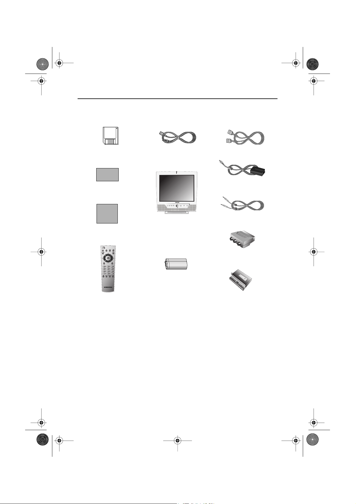
Please make sure the following items are included with your monitor. If any items are missing,
contact your dealer.
Driver Installation Diskette
(Not available in all locations)
Warranty Card
(Not available in all locations)
Manual
Remote Controller
Power Cord
TV/Monitor
Batteries
(AAA x 2)
15-pin D-Sub Signal Cable
DC Adapter
Stereo Audio Cable
Scart Jack
Tuner Box
English 3
4_LW15E13C-Body3-13p.fm Page 4 Wednesday, August 8, 2001 4:10 PM
Setting up Your LCD TV/Monitor
Setting up an Ergonomic Workstation
Consider the advice given below before you install your monitor.
TV/Monitor location
Choose a position that exposes your monitor to the least reflection from lights or windows,
usually at a right angle to any window.
Workstation height
Place your LCD monitor so that the top of the screen is slightly below your eye level when you
are comfortably seated.
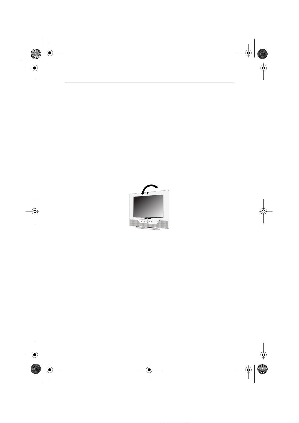
Viewing angle
Tilt the screen until you feel comfortable working with your monitor.
Figure 1. Tilt the screen
English 4
)
)
)
4_LW15E13C-Body3-13p.fm Page 5 Wednesday, August 8, 2001 4:10 PM
Setting up Your LCD TV/Monitor
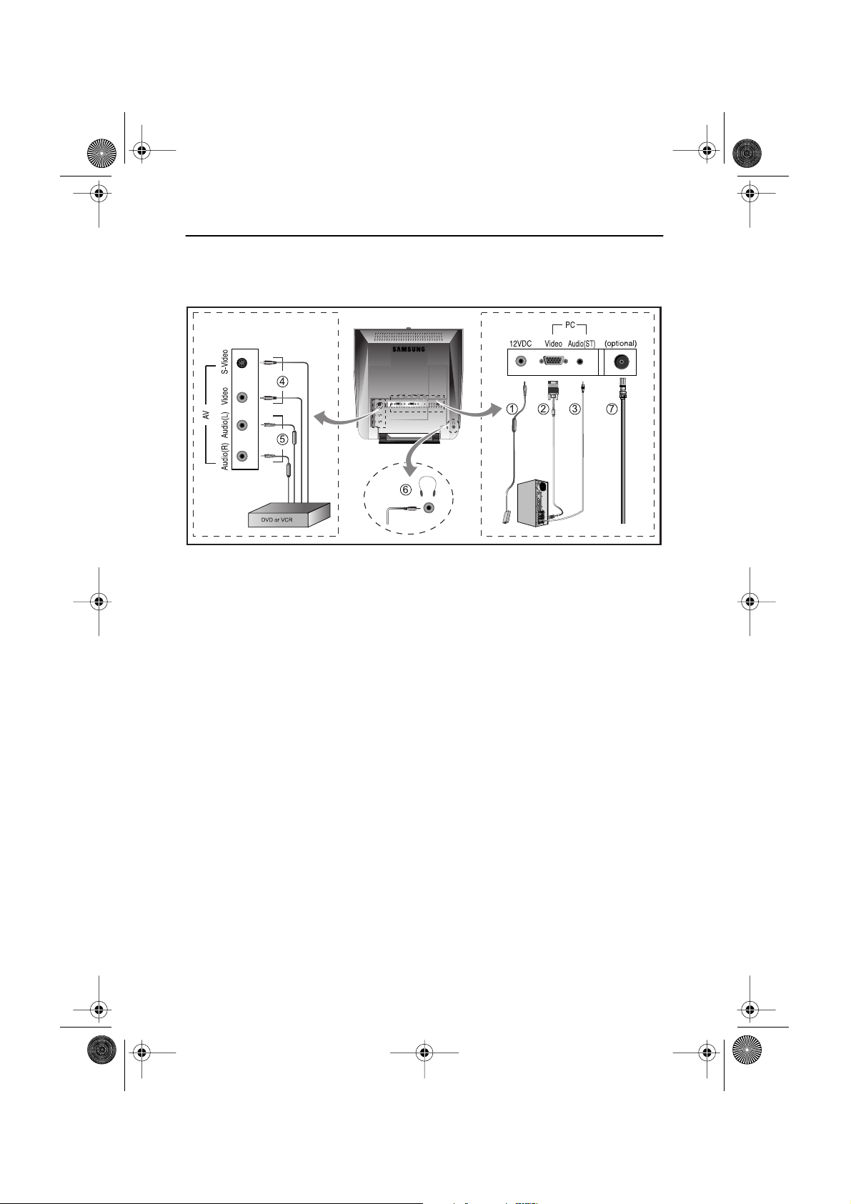
Connecting Your LCD TV/Monitor
Figure 2. Cable connections
1. Connecting Computer (
A. Connect the power cord to the DC Adaptor and connect the adaptor jack to the DC 12V
power connector on the back of the monitor.
B. Connect the 15-pin D-SUB of the video signal cable to the PC video connector on the
back of the monitor.
C. Connect the stereo audio cable to “Audio (ST)” on the back of the monitor and the other
end to “ Audio Out” terminal of the sound card on your computer.
D. If necessary, please install monitor driver contained on the accompanied CD. For driver
installation, please refer “Installing Video Driver” section on page 7.
2. Connecting External A/V Devices (
A. Connect RCA (Yellow) or S-VHS cable to an appropriate external A/V device such as
VCR, DVD or camcorder. (RCA cable and S-VHS cable not included)
B. Connect RCA audio cables to “Audio (R)” and “Audio (L)” terminals and the other ends
to corresponding audio out terminals on the A/V device. (
C. Headphone may be connected to the headphone output on the left-hand side of the
monitor marked (
built-in speakers will be disabled.
D. The DTV function is not supported in this model.
3. Connecting TV/CATV (
A. Connect an antenna or CATV cable to the antenna terminal on the back of the monitor.
➀
➁
➂
➃
➄
Stereo-RCA cable
➅
). While the headphone is connected, the sound from the
not included)
➆
English 5
4_LW15E13C-Body3-13p.fm Page 6 Wednesday, August 8, 2001 4:10 PM
Setting up Your LCD TV/Monitor
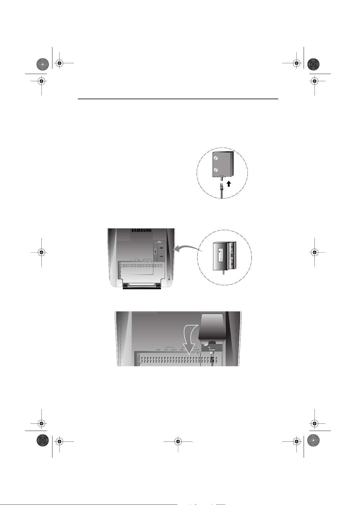
Connecting TV Tuner Box
Unplug the DC adapter.
1
Isolate the cap of the tuner box.
2
Connect antenna or CATV cable to
3
“Antenna” port of the tuner box.
Insert the tuner box to the area for optional tuner box on the back of the monitor.
4
Please use a coin to tighten the two scerws to fix the tuner.
Put the cap of the tuner box on.
5
Connect the power cord of DC adapter then the monitor will be ready for TV function.
6
English 6
4_LW15E13C-Body3-13p.fm Page 7 Wednesday, August 8, 2001 4:10 PM
Setting up Your LCD TV/Monitor
Plug and Play
®
The adoption of the new
suming setup. It allows you to install your monitor in a Plug and Play compatible system without the usual hassles and confusion. Your PC system can easily identify and configure itself
for use with your display. This monitor automatically tells the PC system its Extended Display
Identification Data (EDID) using Display Data Channel (DDC) protocols so the PC system can
automatically configure itself to use the flat panel display. If your PC system needs a video
driver, follow the instructions given below according to the operating system your computer
uses.
VESA
Plug and Play solution eliminates complicated and time con-
Installing the Video Driver
The CD that accompanies this product contains the necessary drivers for installing your monitor. Please refer to the driver installation instructions included with your CD package for more
information.
Self-Test Feature Check (STFC)
Your monitor provides a self-test feature that allows you to check whether your monitor is functioning properly. Make sure that PC is selected as a primary source by checking if the source indicator
LED labeled “PC” is on. If your monitor and computer are properly connected but the monitor screen
remains dark and the power indicator is blinking, run the monitor self-test by following the steps
given below:
Power Indicator
Figure 3. Power Indicator
1
Turn off both your computer and the monitor.
2
Unplug the video cable from the back of the computer.
3
Turn on the monitor.
English 7
4_LW15E13C-Body3-13p.fm Page 8 Wednesday, August 8, 2001 4:10 PM
Setting up Your LCD TV/Monitor
If the monitor is functioning properly, you will see a white box with a large blue oval Samsung
logo and an error messsage “Check Signal Cable.” in red color.
Check Signal Cable
Figure 4. Monitor self-test screen
This box also appears during normal operation if the video cable becomes disconnected or
damaged.
Turn off your monitor and reconnect the video cable; then turn on both your computer and
4
the monitor.
If your monitor screen remains blank after following the previous procedure, check your video
controller and computer system; your monitor is functioning properly.
Getting Help
If your monitor does not display an image, check your cable connections and refer to
"Troubleshooting" on page 25. If you experience difficulties with the quality of the displayed
image, push Auto Button (see page 9) and refer to "Adjusting Your LCD Monitor" on page 9 or
"Troubleshooting" on page 25.
Warm-up Time
All LCD monitors need time to become thermally stable whenever you turn on the monitor after letting the monitor be turned off for a couple of hours. Therefore, to achieve more accurate
adjustments for parameters, allow the LCD monitor to warm (be on) for at least 20 minutes
before making any screen adjustments.
English 8
6
4_LW15E13C-Body3-13p.fm Page 9 Wednesday, August 8, 2001 4:10 PM
Adjusting Your LCD TV/Monitor
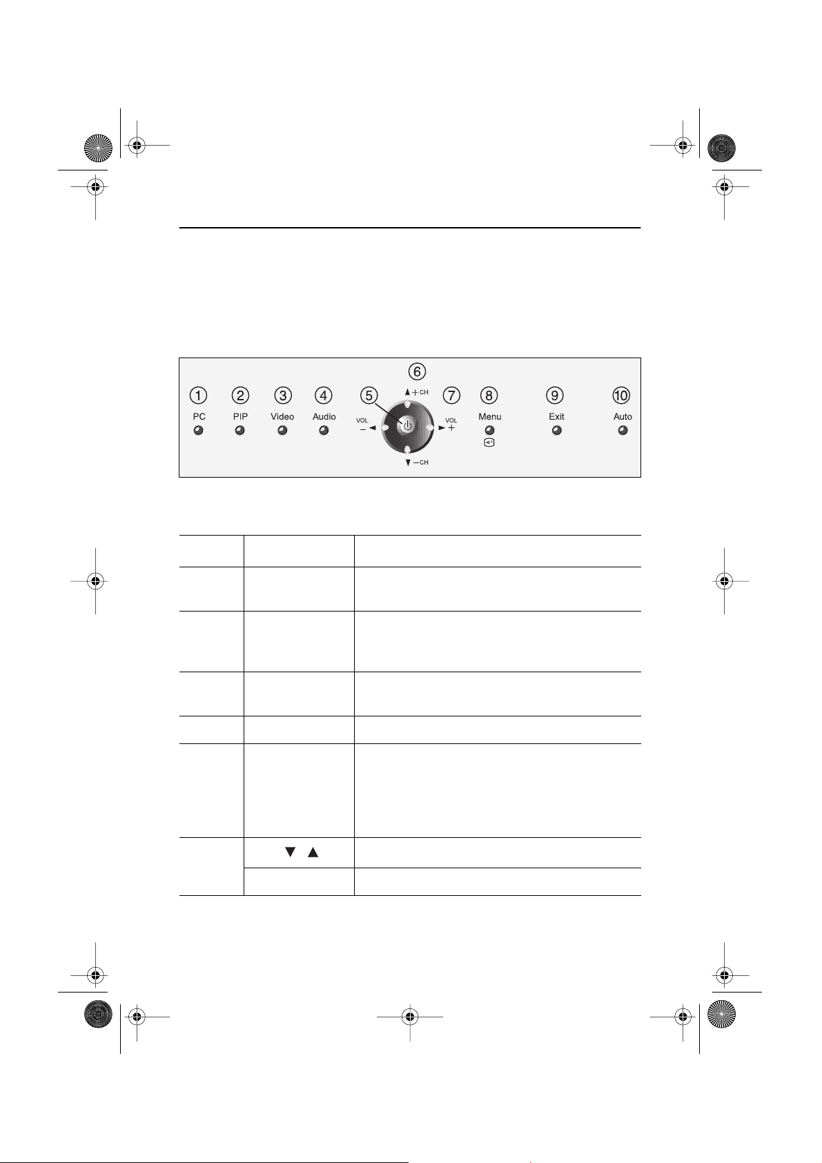
User Controls
Your LCD monitor allows you to easily adjust the characteristics of the image being displayed.
All of these adjustments are made using the control buttons on the front of the monitor. While
you use these buttons to adjust the controls, an OSD shows you their numeric values as they
change.
Figure 5. User control locations
No. Name Description
1 PC
2 PIP
3
Video
4 Audio
5 Power
Selects PC source.
PIP window off.
Activates PIP(Picture-in-Picture) window directly
in PC mode.
Selects video sources (Video/S-video/TV).
Activates full screen video window.
Selects video sources (Video/S-video/TV).
Selects audio source (PC/Video/TV).
Turns ON/OFF the monitor.
Indicates the status of the monitor.
-Green : Normal Operation.
-Amber : Power Saving Mode or Disconnected Signal Cable.
- CH +
Moves the selector up or down on the OSD.
Increases or decreases the channel number.
English 9
4_LW15E13C-Body3-13p.fm Page 10 Wednesday, August 8, 2001 4:10 PM
Adjusting Your LCD TV/Monitor
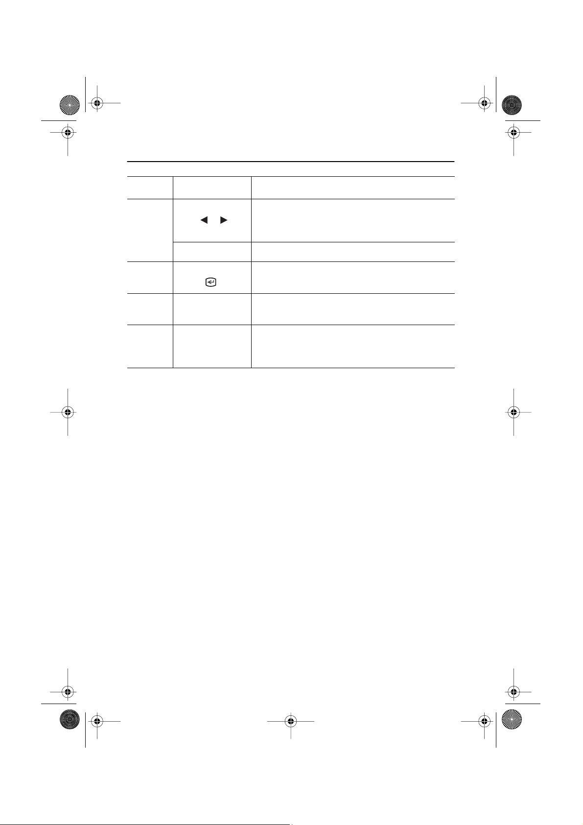
No. Name Description
Moves the selector left or right on the OSD.
Increases or decreases the values of the selected
function.
7
Increases or decreases the level of audio volume.
Opens the OSD and selects the highlighted
function.
Exits from menus and sub-menus.
Exits from the OSD system.
“Auto” allows the monitor to self-adjust to the
incoming video signal. The values of fine, coarse
10
- VOL +
8
9
Menu
Exit
Auto
and position are adjusted automatically.
Automatic Save
Whenever you open the OSD and allow an adjustment window to remain active for about 3
seconds without pressing other buttons, the monitor automatically saves any adjustment you
have made. These changes are saved into a user area in the monitor.
The monitor can save adjustments for up to 5 user modes. It has 9 for LW15E13C (11 for
LW17E14C ) factory preset or preload modes, one for each signal frequency as listed in table
7 on page 31. If you have made no adjustments, the OSD disappears and the monitor does not
save anything.
English 10
•
•
•
4_LW15E13C-Body3-13p.fm Page 11 Wednesday, August 8, 2001 4:10 PM
Adjusting Your LCD TV/Monitor
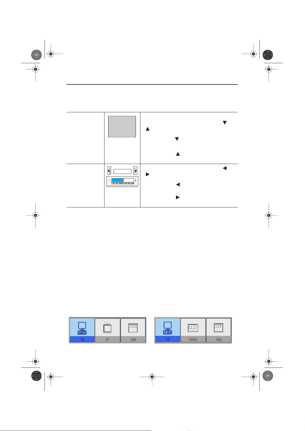
Direct-Access Features
While you are watching full screen TV or in PIP mode
P_
Program
Volume
Volume
Valid only after performing "Channel auto program".
When OSD is not on the screen, push the " " or
" " button to select program channel number.
Push the " " button to decrease channel
1
number .
Push the " " button to increase the
2
channel number.
When OSD is not on the screen, push the " " or
" " button to adjust volume.
Push the " " button to decrease the
1
volume.
Push the " " button to increase the
2
volume.
OSD Lock/Unlock
While OSD window is not on, push and then hold Menu button for about 5 seconds to Lock or
Unlock OSD menus. When OSD menus are locked, all OSD menus are disabled and colored in
gray to indicate that those functions are not accessible but the following functions:
1. PC
Brightness • Contrast
2. TV
Channel • Volume
3. Control buttons
Direct access keys: PC, PIP, Video, Audio, Channel, Volume, Menu, Exit, Auto
4. Remote Controller
•
All direct access keys on the remote controller
Initial OSD icons
Depending on the configuration of the monitor, the appearance of OSD is different.
Fig. 6. With Optional TV Tuner Fig. 7. Without Optional TV Tuner
English 11

4_LW15E13C-Body3-13p.fm Page 12 Wednesday, August 8, 2001 4:10 PM
Adjusting Your LCD TV/Monitor
➮ Some OSD menus are disabled in gray color when they are not available in a certain mode
of operation. Those menus are enabled when corresponding OSD menus are activated.
On Screen Display (OSD)
Accessing the menu system
With the OSD off, push the Menu button to display the main OSD menu.
1
Use the " " buttons to move from one function to another. As you move
2
from one icon to another, the function name changes to reflect the function or group of
functions represented by that icon. See Table 1 starting on the next page to view a
complete list of all of the functions available for the monitor.
Press the Menu button once to activate the highlighted function, then follow the Tool
3
Tips to select the function and adjust the value.
Use " " and " " buttons to select the sub-menu, and press the Menu button once
4
to activate the selected sub-menu.
After selecting a function, use the " " and " " buttons to make necessary
5
adjustments. The setting bar moves and the numeric value indicator changes to reflect
your adjustments.
NOTE: The numeric value indicator is provided as a point of reference only and has
nothing to do with a real measurement.
Push the Exit button a couple of times to return to the main menu to select another
6
function or to exit from the OSD.
English 12

4_LW15E13C-Body3-13p.fm Page 13 Wednesday, August 8, 2001 4:10 PM
Adjusting Your LCD TV/Monitor
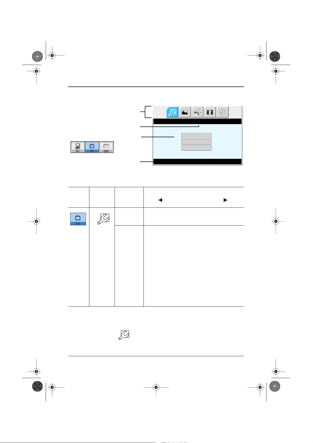
OSD functions and adjustments
Function icons
Function name
Setting bar
Main menu
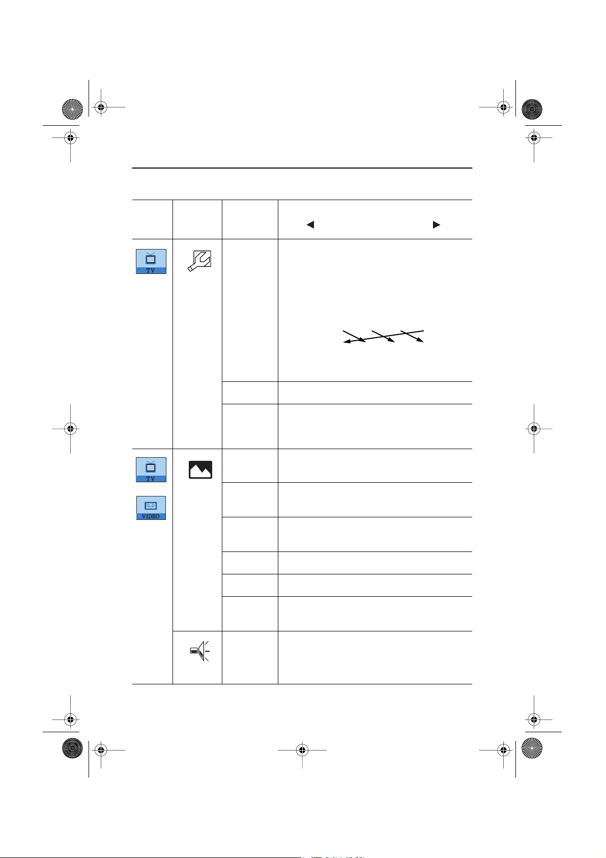
Table 1. Screen controls
Main
Menu
Icon
Menus and
Sub-menus
LANGUAGE
POSITION Move the OSD Window to the vertical and
Tool Tip
LANGUAGE
Language
Function Descriptions
Press Key
OSD language and appearence can be changed.
English
Deutsch
Español
Français
Italiano
Svenska
horizontal direction.
HALFTONE Change the opaqueness of the background of the
OSD.
DURATION The number of seconds that the OSD will remain
visible before disappearing.
BEEP Enables or Disables the sound generated when
you touch the control buttons.
English 13

5_LW15E13C-Body14-17p.fm Page 14 Wednesday, August 8, 2001 4:11 PM
Adjusting Your LCD TV/Monitor
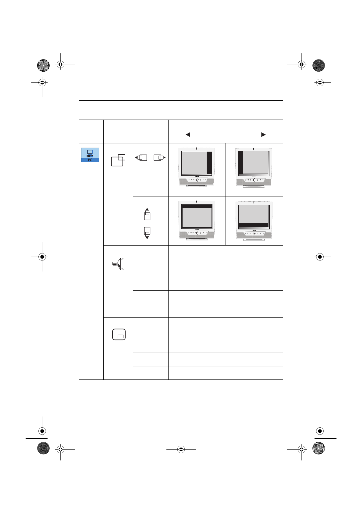
PC functions and adjustments
Function icons
Function name
Setting bar
Main menu
Tool Tip
Table 1. Screen controls (Continued)
Main
Menu
Icon
Menus and
Sub-menus
CONTRAST
BRIGHTNESS
CONTRAST
Contrast
Function Descriptions
Press Menu Key
COLOR
The tone of color can be changed from redish
white to bluish white. The individual color
components are also user customizable.
Mode1 Redish white.
Mode2 Plain white.
Mode3 Bluish white.
User Mode User customizable.
English 14

5_LW15E13C-Body14-17p.fm Page 15 Wednesday, August 8, 2001 4:11 PM
Adjusting Your LCD TV/Monitor
Table 1. Screen controls (Continued)
Main
Menu
Icon
Menus and
Sub-menus
Reset Color parameters are replaced with the factory
Function Descriptions
default values.
IMAGE
Image Lock is used to fine tune and get the best
image by removing noises that create unstable
IMAGE LOCK
Coarse
Fine
images with jitters and shimmers.
The Coarse and Fine adjustments allow you to
fine tune the image quality of your monitor to
your preference.
Use the " " and " " buttons to remove any
noise.
If satisfactory results are not obtained using the
Fine adjustment, use the Coarse adjustment and
then use Fine again.
This function may change the width of the image.
Use the H-Position menu to center the image on
the screen.
When
Coarse
value is
wrong.
When
wrong.
Fine
value is
Information Display current display mode.
Reset Image lock and position parameters are replaced
with the factory default values.
English 15

5_LW15E13C-Body14-17p.fm Page 16 Wednesday, August 8, 2001 4:11 PM
Adjusting Your LCD TV/Monitor
Table 1. Screen controls (Continued)
Main
Menu
Icon
Menus and
Sub-menus
IMAGE SIZE
The size of the image being displayed can be
Function Descriptions
handled in several different ways.
Expand1 Resize the image to fill the whole screen.
(applicable to PC RGB only)
Expand2 Expand images keeping the original aspect ratio.
(applicable to PC RGB only)
Normal Display the incoming image as it is.
(applicable to PC RGB only)
Zoom The image can be magnified up to 64 times larger
than the original image. The enlarged image can
also be panned.
Pan Move the zoomed image hotizontally and
vertically.
IMAGE
EFFECT
Image being displayed can be made softer or
sharper.
• Sharpen more
• Sharpen
• Medium
• Soften
• Soften more
English 16
5_LW15E13C-Body14-17p.fm Page 17 Wednesday, August 8, 2001 4:11 PM
Adjusting Your LCD TV/Monitor
Table 1. Screen controls (Continued)
Main
Menu
Icon
Menus and
Sub-menus
Function Descriptions
H-POSITION
V-POSITION
The monitor has a built-in high fidelity stereo
SOUND
audio amplifier. The audio circuit processes audio
signal from various external input sources such
as DVD, VCR, TV or PC.
Bass Bass: Emphasize low frequency audio.
Treble Treble: Emphasize high frequency audio.
Surround On, Off
PIP
(Picture-inPicture)
When external A/V devices such as VCR, DVD or
RF(TV)cable are connected to the monitor, PIP
allows you to watch video from such devices in a
small window super-imposed on pc video signal.
Size Resize PIP window.
Position Change PIP window position.
English 17
6_LW15E13C-Body18p.fm Page 18 Wednesday, August 8, 2001 4:14 PM
Adjusting Your LCD TV/Monitor
TV/ Video functions and adjustments
Function icons
Function name
Setting bar
Main menu
Table 1. Screen controls (Continued)
Main
Menu
Icon
Tool Tip
Menus and
Sub-menus
SET-UP
Channel
*
system
SET-UP
Channel System
Manual Tune
Channel Sort
Set-Up Press Menu Key
Function Descriptions
The channel system can be set in several different
ways.
Select a channel system that is being used in your
region.
(See "PAL broadcasting systems" on page 32)
• CCIR
• Italy
• IRE
• Australia
Upon selecting a channel system, you will be
asked if you want to perform "Channel auto
program ". Select "OK " to perform the "Channel
auto program " or select "Cancel" to select
different channel system.
It takes 8 minutes in average to scan 70 channels. The amount of time to fin-
*
ish channel scanning is completely depending on the number of channels
avilable in your region.
TV menu ( ) is available only aftrer the installation of TV tuner.
*
Before installing the TV tuner, Menus are all in gray color and navigation is
disabled as well.
English 18
6_LW15E13C-Body18p.fm Page 19 Wednesday, August 8, 2001 4:14 PM
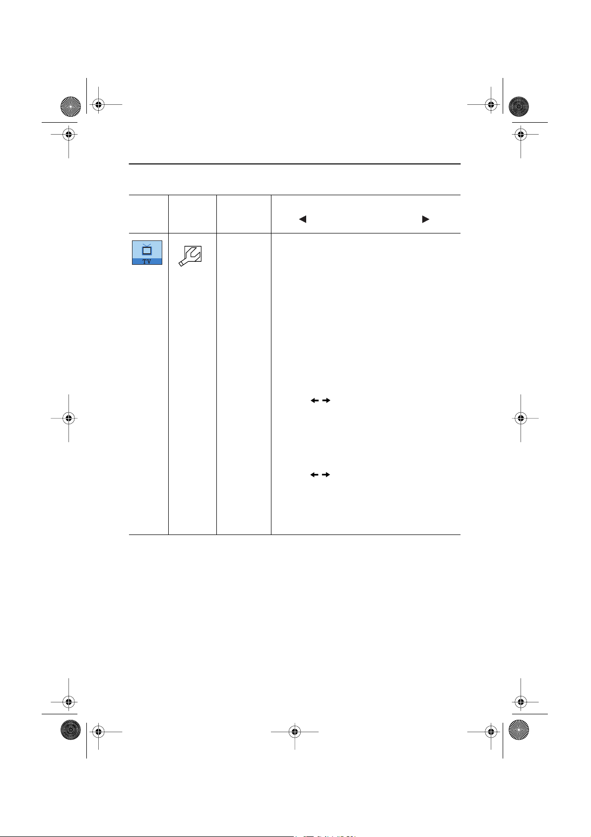
Adjusting Your LCD TV/Monitor
Table 1. Screen controls (Continued)
Main
Menu
Icon
Menus and
Sub-menus
Manual
Tune
Function Descriptions
Due to the weak signals or a wrong antenna
configuration, some of the channels may not be
tuned correctly or there could be a mismatch of
the channel
a Program
number between a Real channel and
channel. Use this menu to fine tune
and perform necessary corrective actions.
• Program : Program numbers are given in a
sequential manner based on the search order
of Channel Auto Program.
• Channel: Channel numbers are given
according to the CCIR or Australia standard
channel table.
• Save
- Use buttons to fine tune the picture
quality
and then select "Save"menu.
Now
press "Menu" button to save the fine tuned
channel.
• Add
- Use this function to add a real channel.
- Use buttons to select a desired
channel and then select "Add" menu. Now
press "Menu" button to add the channel.
• Cancel
- Use this menu to undo the current job.
English 19
6_LW15E13C-Body18p.fm Page 20 Wednesday, August 8, 2001 4:14 PM
Adjusting Your LCD TV/Monitor
Table 1. Screen controls (Continued)
Main
Menu
Icon
Menus and
Sub-menus
Channel
Sort
Channel order can be re-arranged by this menu.
If you want to place P5 before P2, see the
Function Descriptions
example below.
Example) From : P5
To : P2
Before: P1 P2 P3 P4 P5
New: [ P1 P5 P2 P3 P4 ]
P1 P2 P3 P4 P5
Store
Channel
Delete
Select "store" menu to save the adjustment.
Select a channel you wish to delete by using the
" From" menu, them select "Channel Delete" to
delete the selected channel.
PICTURE
Contrast Adjust the contrast of video or TV without
This funtion is active if you select an input source
other than PC.(DVD,VCR,TV)
affecting PC RGB’s contrast.
Brightness
Adjust the brightness of video or TV without
affecting PC RGB’s brightness.
Sharpness
Color Change the richness of color.
Reset
Adjust the sharpness of video or TV image.
Picture parameters are replaced with the factory
default values.
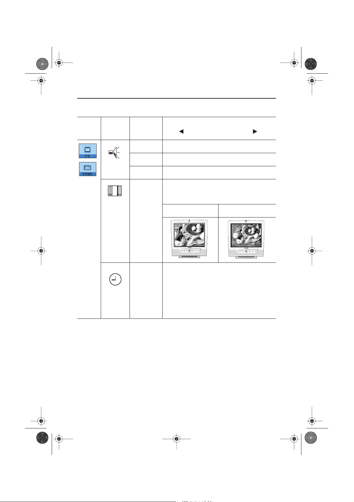
The monitor has a built-in high fidelity stereo
SOUND
audio amplifier. The audio circuit processes audio
signal from various external input sources such
as DVD, VCR, TV or PC.
English 20
6_LW15E13C-Body18p.fm Page 21 Wednesday, August 8, 2001 4:14 PM
Adjusting Your LCD TV/Monitor
Table 1. Screen controls (Continued)
Main
Menu
Icon
Menus and
Sub-menus
Bass Bass: Emphasize low frequency audio.
Treble Treble: Emphasize high frequency audio.
Surround On, Off
ACTIVE
AREA
The Active Area of the image being displayed can
be handled in Narrow and Wide.
Function Descriptions
This funchin is not working in PIP.
Narrow Wide
TIMER The monitor system will turn off automatically if
one of three time intervals is selected.
Off.
30 min.
60 min.
120 min.
English 21
6_LW15E13C-Body18p.fm Page 22 Wednesday, August 8, 2001 4:14 PM
Appendix
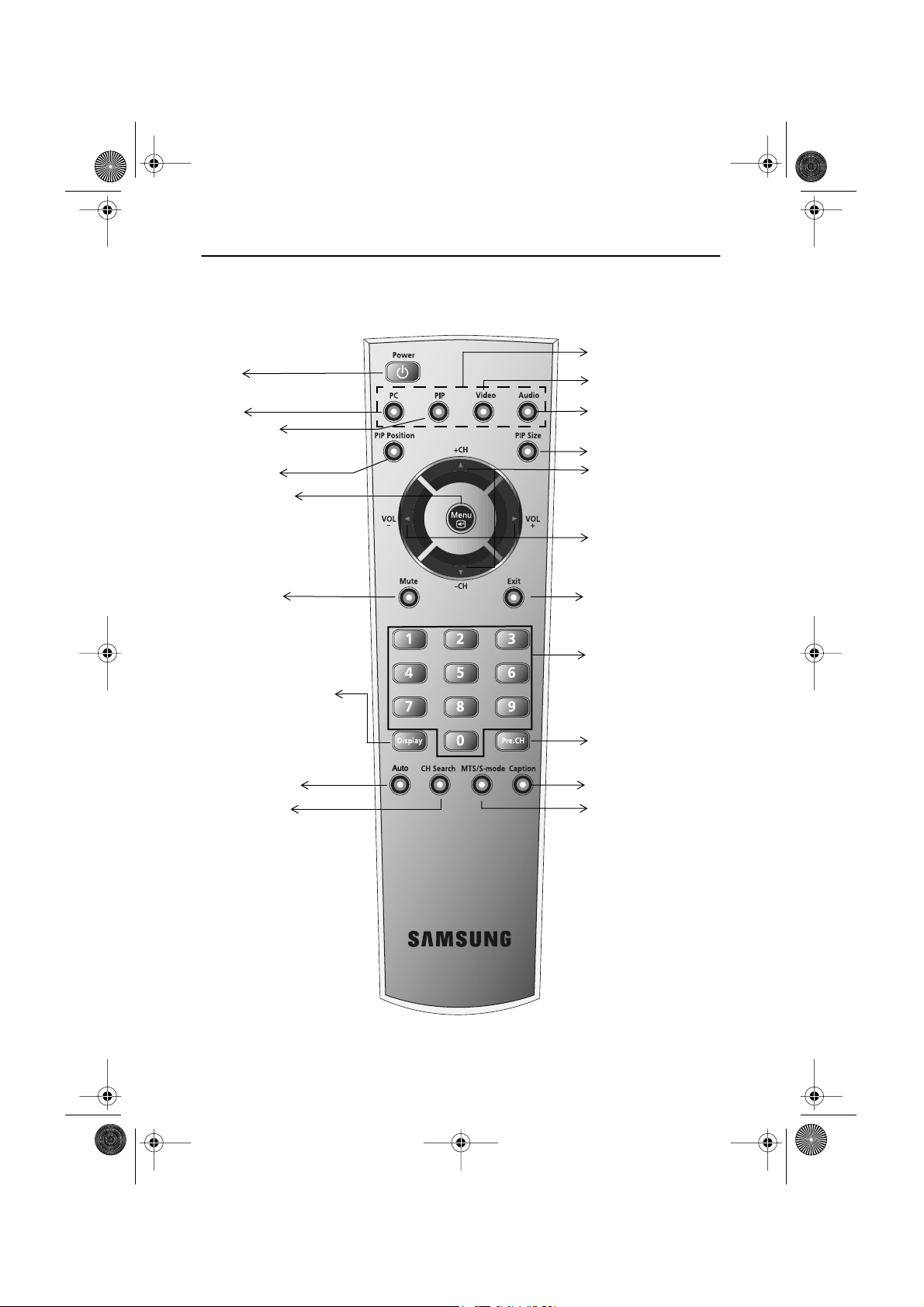
By Remote-Control
Power
On/Off
PC on
PIP PC+Video
PIP Position
Turn on the OSD
Select a function
“Source Control keys.”
Video (TV/ VCR or DVD)
Audio
PIP size
Channel
Up/Down
Volume
Up/Down
Sound mute
Display setup information
(Video source, Audio source,
Channel number, Sound mode,
Audio mute on/off)
Auto Adjustment
Channel search
Turn off the OSD
Numeric keypads for
direct channel access.
Previous channel
Caption (USA Only)
MTS-mode (USA)
or S-mode (Europe)
English 22

6_LW15E13C-Body18p.fm Page 23 Wednesday, August 8, 2001 4:14 PM
Appendix
Features that can only be accessed via remote controller
Display Shows a selected video source, audio soure, current channel number
sound mode and the state of audio mute on the upper right corner of the
screen.
• Video Source: _
• Audio Source: _
• PI/Mono
• Sound Mute: off
MTS/S-Mode You can set the audio mode by using this button. When you press this
button, current sound mode is displayed on the lower left corner of the
screen
Stereo
Note: LW15E13C/LW17E14C have an automatic stereo detection
feature. Thus, depending on the types of audio, the monitor
automatically changes their audio mode from Mono to Stereo
or vice versa.
Audio Type MTS/S-Mode Default
FM Stereo Mono Mono
Automatic Change
Stereo Mono Stereo
Dual Dual1 Dual2 Dual1
NICAM Mono Mono
Automatic Change
Stereo Mono Stereo
Dual Mono Dual1 Dual2 Dual1
English 23

6_LW15E13C-Body18p.fm Page 24 Wednesday, August 8, 2001 4:14 PM
Appendix
PowerSaver
This monitor has a built-in power management system called PowerSaver. This system saves
energy by switching your monitor into a low-power mode when it has not been used for a
certain period of time. The available modes are “On”, “Standby”, “Sleep”, and “Deep Sleep”.
PowerSaver operates with a VESA DPMS compliant video card installed in your computer. You
use a software utility installed on your computer to set up this feature. See Table 2 below for
details.
Table 2. Power-saving modes
Power-Saving Function mode
State
Horizontal Sync
Vertical Sync
Power
Indicator
Normal
Operation
Active
Active
Standby Mode
Inactive
Active
Green Amber Amber Blinking
(EPA/ NUTEK/ ENERGY2000)
Sleep Mode
Position A1
Active
Inactive
Deep Sleep Mode
Inactive
Inactive
Amber Blinking
(0.5 sec interval)
(1 sec interval)
Position A2
LW15E13C :
Power
Consumption
40W (Max.)
LW17E14C :
Less than 3W Less than 3W Less than 3W
52W (Max.)
NOTE: This monitor automatically returns to normal operation when horizontal and vertical
sync return. This occurs when you move the computer’s mouse or press a key on the
keyboard.
This monitor is EPA E
NERGY
®
TAR
S
compliant and NUTEK/ENERGY2000 compliant when used
with a computer equipped with VESA DPMS functionality.
For energy conservation, turn your monitor OFF when you are not using it or when leaving it
unattended for long periods.
English 24

6_LW15E13C-Body18p.fm Page 25 Wednesday, August 8, 2001 4:14 PM
Appendix
Troubleshooting
If you have a problem setting up or using your LCD monitor, you may be able to solve it
yourself. Before contacting customer service, try the suggested actions that are appropriate
to your problem.
Table 3. Troubleshooting – Image
What you see... Suggested Actions Reference
Screen is black and
power indicator is off
“ Check Signal Cable”
message
“Sync. Out of Range”
message
The image is too light
or too dark
Horizontal bars appear
to flicker, jitter or
shimmer on the image
Vertical bars appear to
flicker, jitter or
shimmer on the image.
Ensure that the power cord is
firmly connected and the LCD
Connecting your LCD
monitor, page 5.
monitor is on.
Ensure that the signal cable is
firmly connected to the PC or
Connecting your LCD
monitor, page 5.
video sources.
Ensure that the PC or video
sources are turned on.
Check the maximum
Display Modes, page 31.
resolution and the frequency
of the video adaptor.
Compare these values with
the data in the Display Modes
Timing Chart.
Adjust the Brightness and
Contrast.
Adjust the Fine function. Image Lock, Fine,
Brightness, page 14.
Contrast, page 14.
page 15.
Adjust the Coarse function
and then adjust the Fine
function.
Image Lock, Coarse, page 15.
Image Lock, Fine,
page 15.
English 25

6_LW15E13C-Body18p.fm Page 26 Wednesday, August 8, 2001 4:14 PM
Appendix
Table 3. Troubleshooting – Image (Continued)
What you see... Suggested Actions Reference
Screen is black and
power indicator light
is steady amber or
blinks every 0.5 or 1
seconds
Image is not stable
and may appear to
vibrate
The monitor is using its power
Power Saver, page 24.
management system.
Move the computer’s mouse
or press a key on the keyboard
Check that the display
Display Modes, page 31.
resolution and frequency from
your PC or video board is an
available mode for your
monitor. On your computer
check: Control Panel, Display,
Settings
If the setting is not correct,
use your computer utility
Installing the Video Driver,
page 7.
program to change the display
settings.
NOTE: Your monitor supports multiscan display functions within
the following frequency domain:
Horizontal frequency:
LW15E13C : 30 kHz ~ 69 kHz
LW17E14C : 30 kHz ~ 81kHz
Image is not centered
on the screen.
You need the monitor
driver software
Vertical frequency:
Maximum refresh rate:
56 Hz ~ 85 Hz
LW15E13C :
1024 x 768 @ 85 Hz
LW17E14C :
1280 x 1024 @ 76Hz
Adjust the horizontal and
vertical position.
Download the driver from WWW pages:
H-Position, page 17.
V-Position, page 17.
http://www.samsung-monitor.com
http://www.samsungmonitor.com (USA Only)
English 26

6_LW15E13C-Body18p.fm Page 27 Wednesday, August 8, 2001 4:14 PM
Appendix
Table 4. Troubleshooting – Audio and TV
Problem Suggested Actions Reference
No sound Ensure that the audio cable is firmly
connected to both the audio-in port
on your monitor and the audio–out
port on your sound card.
Check the volume level Sound Controls.
Sound level is
Check the volume level Sound Controls.
too low
If the volume is still too low after
turning the control to its maximum,
check the volume control on the
computer sound card or software
program.
Sound is too high
pitched or too
Adjust the Treble and Bass to
appropriate level.
low pitched
TV signal is not
received
Check “Channel system” and make
sure you choose the correct channel
system.
Select “Channel auto program” to
configure the channel system
automatically.
Check “TV Tuner Box” see “Connec-
ting TV Tuner Box” on page 6.
Connecting your LCD
Monitor, page 5.
Refer to your computer,
sound card or software
documentation.
Sound Controls, page 17.
See "PAL broadcasting
systems" on page 32.
English 27

6_LW15E13C-Body18p.fm Page 28 Wednesday, August 8, 2001 4:14 PM
Appendix
Specifications
Table 5. Technical and environmental specifications
LW15E13C LW17E14C
Panel Size
Display Size
Type
Pixel pitch
Viewing Angle
* Frequency Horizontal
Vertical
Display color
Display
Resolution
Input Signal Sync.
TV, Video Color system
Optimum Mode
Maximum Mode
Video signal
Sound system
Video format
15.0” Diagonal
304.1 (H) x 228.1 (V) mm
a-si TFT active matrix
0.297 (H) x 0.297 (V) mm
70/70/60/60 (L/R/U/D)
(Depending on the panel
manufacturer, the viewing
angle may be different from
this spec.)
30 ~ 69 kHz
56 ~ 85 Hz
16,777,216 colors
1024 x 768 @ 60 Hz
1024 x 768 @ 85 Hz
H/V Separate, TTL, P. or N.
H/V Composite, TTL, P. or N.
Sync-on-green 0.3 Vp-p, N.
0.7 Vp-p @ 75 ohm
PAL
B/G, D/K, I
CVBS, S-VHS
17.0” Diagonal
338 (H) x 270 (V) mm
a-si TFT active matrix
0.264 (H) x 0.264 (V) mm
80/80/80/80 (L/R/U/D)
(Depending on the panel
manufacturer, the viewing
angle may be different from
this spec.)
30 ~ 81 kHz
56 ~ 85 Hz (~XGA)
60 ~ 76 Hz (SXGA)
16,777,216 colors
1280 x 1024 @ 60 Hz
1280 x 1024 @ 76 Hz
Video Color system PAL/NTSC/SECAM
Power Supply Input
Output
* Referring to Preset timing modes, page 31.
96 ~ 264 VAC rms (50Hz / 60Hz)
DC 12V/4.5A
English 28

6_LW15E13C-Body18p.fm Page 29 Wednesday, August 8, 2001 4:14 PM
Appendix
Table 5. Technical and environmental specifications (Continued)
LW15E13C LW17E14C
Power
Consumption
Dimensions/
Weight
Environmental
Considerations
Audio
Characteristics
Maximum
Power Saving
Unit (WxHxD) :
Monitor body
With stand
When folded
Operating
Temperature
Operating
Humidity
Storage
Temperature
Storage
Humidity
Audio Input 1
Audio Input 2
Headphone out
Frequency
Response
40 W
< 3 W
14.1 x 13.8 x 2.0 inch / 7.2 lbs
(358.6 x 351.1x 51 mm / 3.3 kg)
14.1 x 14.2 x 6.9 inch / 7.7 lbs
(358.6 x 360.1 x 175.5 mm / 3.5 kg)
14.1 x 15.9 x 2.0 inch / 7.7 lbs
(358.6 x 402.6 x 51 mm / 3.5 kg)
50 ˚F to 104 ˚F (10 ˚C to 40 ˚C)
10% to 80%
13 ˚F to 113 ˚F (-25 ˚C to 45 ˚C)
5% to 95%
RCA Jack Red(R) White(L), 0.5Vrms (-9dB)
3.5ø Stereo Jack, 0.5Vrms (-9dB)
Max. 10mW Output (3.5ø Stereo Jack 32Ω)
RF: 80Hz ~ 15kHz (at- 3dB)
A/V: 80Hz ~ 20kHz (at - 3dB)
52 W
< 3 W
16.2 x 16.1 x 2.3 inch / 10.3 lbs
(412 x 408.0 x 58.5 mm / 4.7 kg)
16.2 x 16.5 x 8.0 inch / 11 lbs
(412.0x 418.0 x 203.0 mm / 5 kg)
16.2 x 18.6 x 2.3 inch / 11lbs
(412.0 x 472.0 x 58.5 mm / 5 kg)
English 29

6_LW15E13C-Body18p.fm Page 30 Wednesday, August 8, 2001 4:14 PM
Appendix
Pin Assignments
Table 6. 15 pin D-sub connector
Pin Separate H/V Composite H/V Sync-on-green
1 Red Red Red
2 Green Green Green + H/V Sync
3 Blue Blue Blue
4 GND GND GND
5 GND (DDC Return) GND (DDC Return) GND (DDC Return)
6 GND-Red GND-Red GND-Red
7 GND-Green GND-Green GND-Green
8 GND-Blue GND-Blue GND-Blue
9 No Connection No Connection Not used
10 GND-Sync/Self Test GND-Sync/Self Test GND-Sync/Self Test
11 GND GND GND
12 DDC _SDA DDC _SDA DDC _SDA
13 H_Sync H/V Sync Not used
14 V_ Sync Not used Not used
15 DDC _SCL DDC _SCL DDC _SCL
English 30
6_LW15E13C-Body18p.fm Page 31 Wednesday, August 8, 2001 4:14 PM
Appendix
Display Modes
If the signal from the system equals to the standard signal mode, the screen is adjusted
automatically. If the signal from the system doesn’t equal to the standard signal mode, adjust
the mode with refering to the Videocard user guide because the screen might not display or
only the power LED might be on. For the display modes listed below, the screen image has
been optimized during manufacture.
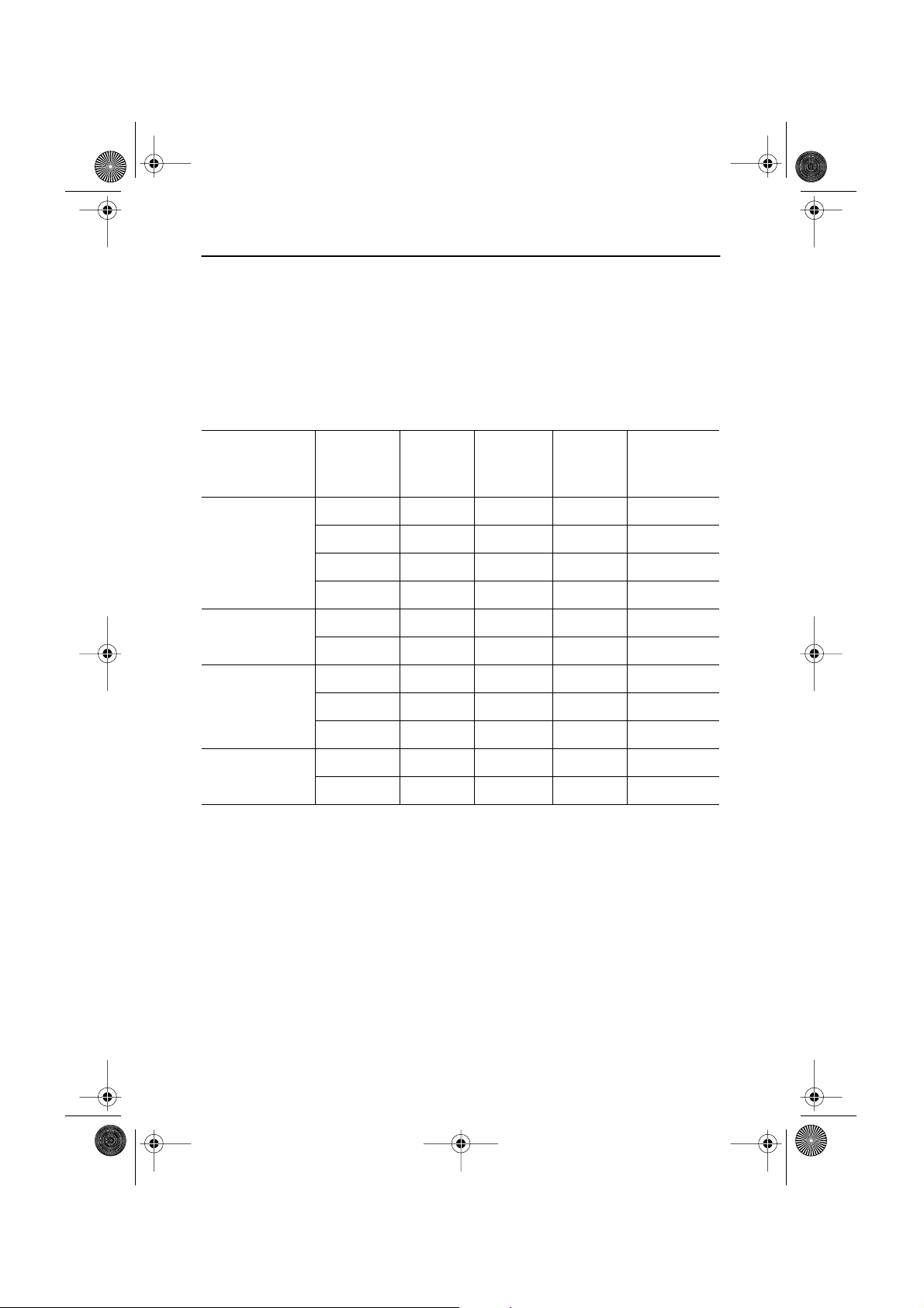
Table 7. Preset timing modes
Mode Resolution
VGA
SVGA
XGA
SXGA
(LW17E14C only)
Horizontal
Frequency
(kHz)
Vertical
Frequency
(Hz)
Pixel Clock
Frequency
(MHz)
Sync Polarity
(H/V)
720 x 400 31.469 70.087 28.322 –/+
640 x 480 31.469 59.940 25.175 –/–
640 x 480 37.500 75.000 31.500 –/–
640 x 480 43.269 85.008 36.000 –/–
800 x 600 46.875 75.000 49.500 +/+
800 x 600 53.674 85.061 56.250 +/+
1024 x 768 48.363 60.004 65.000 –/–
1024 x 768 60.023 75.029 78.750 +/+
1024 x 768 68.677 84.997 94.500 +/+
1280 x 1024 63.981 60.020 108.000 +,–/+,–
1280 x 1024 79.976 75.025 135.000 +/+
English 31
6_LW15E13C-Body18p.fm Page 32 Wednesday, August 8, 2001 4:14 PM
Appendix
Table 8. PAL Broadcasting Systems
Model
Name
LW15E13C
LW17E14C
Color
System
PAL
Sound
System
B/G
I NICAM
Stereo
System
A2
NICAM
Unknown CCIR
Channel
System
CCIR
AUSTRALIA Australia
CCIR
ITALY Italy
CCIR UK,Hongkong
IRELAND Ireland
Countries
Germany,Austria,Swiss,
Netherlands
Sweden,Spain,Denmark,
Norway,Finland,Belgium,
Iceland,Portugal,Malaysia,
Singapore,Thailand
India,Israel,Kuwait,Jordan,
Yugoslavia
English 32
6_LW15E13C-Body18p.fm Page 33 Wednesday, August 8, 2001 4:14 PM
Appendix
Attaching a wall or Arm mounting device
The monitor supports VESA mounting standard for use with various VESA mounting devices.
To install any VESA mounting device, please follow the instructions given.
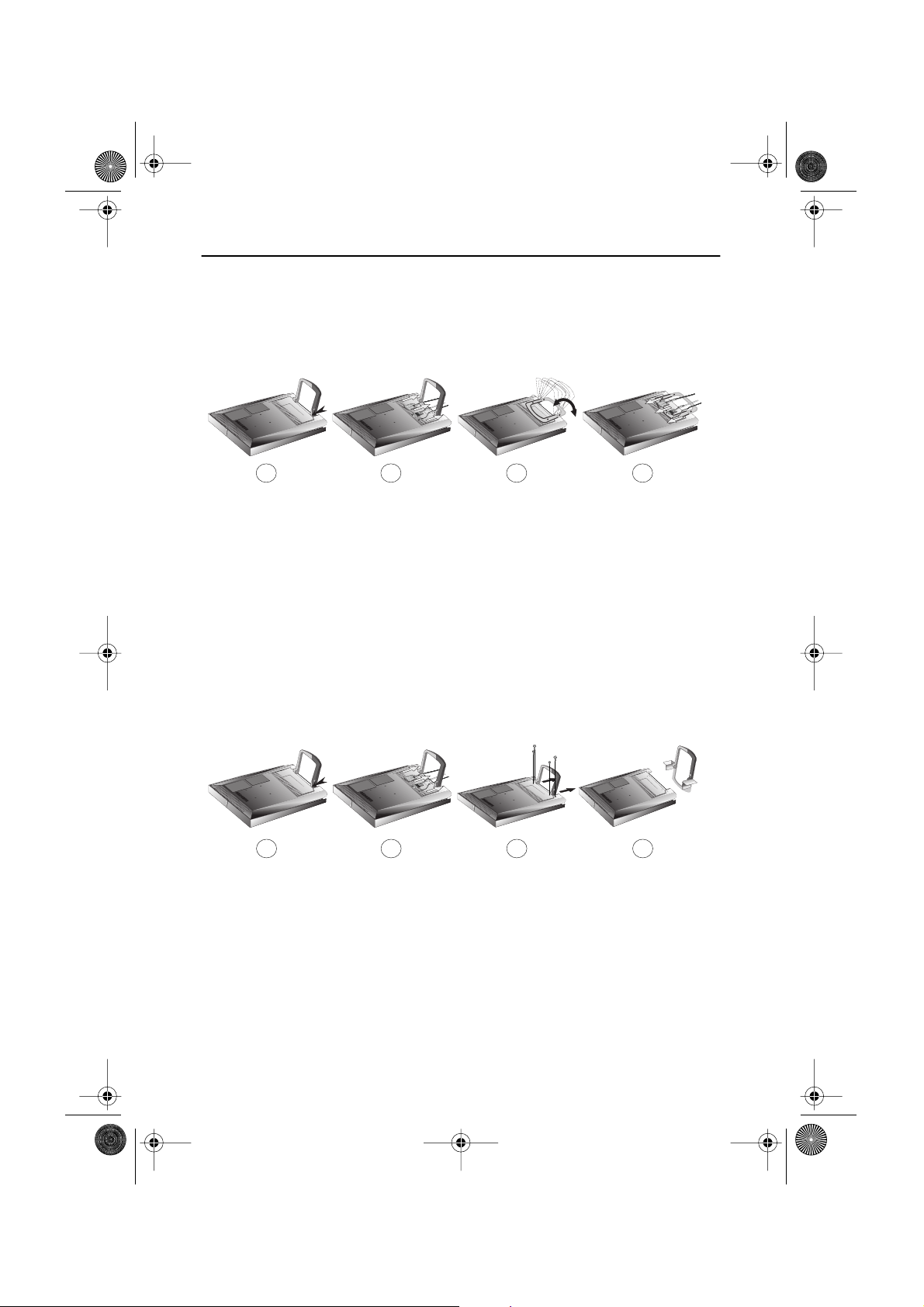
Case 1.
1
Lay the LCD monitor face-down on a flat surface with a cushion or other soft materials
1
to protect the screen.
Remove all cables connected to the monitor.
2
Press “FOLD” button on the stand and tilt the monitor backward until the stand is
3
folded in the monitor.
Connect all cable you removed at step 2.
4
Now you are ready to install Wall/Arm mounting device depending on your
5
applications.
Case 2.
1
Lay the LCD monitor face-down on a flat surface with a cushion or other soft materials
1
to protect the screen.
Remove all cable connected on the monitor.
2
2
2
3 4
3 4
Remove the four screws and then remove the Stand from the LCD monitor.
3
Connect all cable you removeed at step 2.
4
Now you are ready to install Wall/Arm mounting device depending on your
5
applications.
English 33

6_LW15E13C-Body18p.fm Page 34 Wednesday, August 8, 2001 4:14 PM
Appendix
Installing VESA compliant mounting devices
Refer to page 33 to fold the base.
Rear cover
mounting pad
Mounting
Align the mounting interface pad with the holes in the rear cover mounting pad and secure it
with the four screws that came with the arm-type base, wall mount hanger or other bases.
Wall Mount Instructions
The following instructions apply to a hollow sheet-rock wall only Tools/Hardware
needed - Philips screwdriver, four toggle bolts, 5/8in dia. Drill bit and drill. Contact Ergotron at
(800) 888-8458 to purchase the triple pivot direct mount adapter and wall mount bracket kit.
• LW15E13C (15") : No. 47 - 007 - 099 (Pivot direct mount adapter)
No. 97 - 101 - 003 (Wall mount bracket kit)
• LW17E14C (17") : No. 47 - 007 - 099 - 02 (Pivot direct mount adapter)
No. 97 - 101 - 003 - 00 (Wall mount bracket kit)
Align the wall mount bracket on the wall at the desired height, making sure that the bracket
will be mounted between the wall studs. Mark the four corner openings and drill four 5/8-dia.
holes.
Assemble the wall mount kit according to the instructions provided with it.
Securely attach Ergotron’s flat panel, triple pivot direct mount adapter to the back of the
monitor using the four 4mm, .7 pitch x 10mm screws provided with the arm.
Secure the assembly to the wall using four 3/16 by 3-inch long toggle bolts.
English 34
15
6_LW15E13C-Body18p.fm Page 35 Wednesday, August 8, 2001 4:14 PM
Appendix
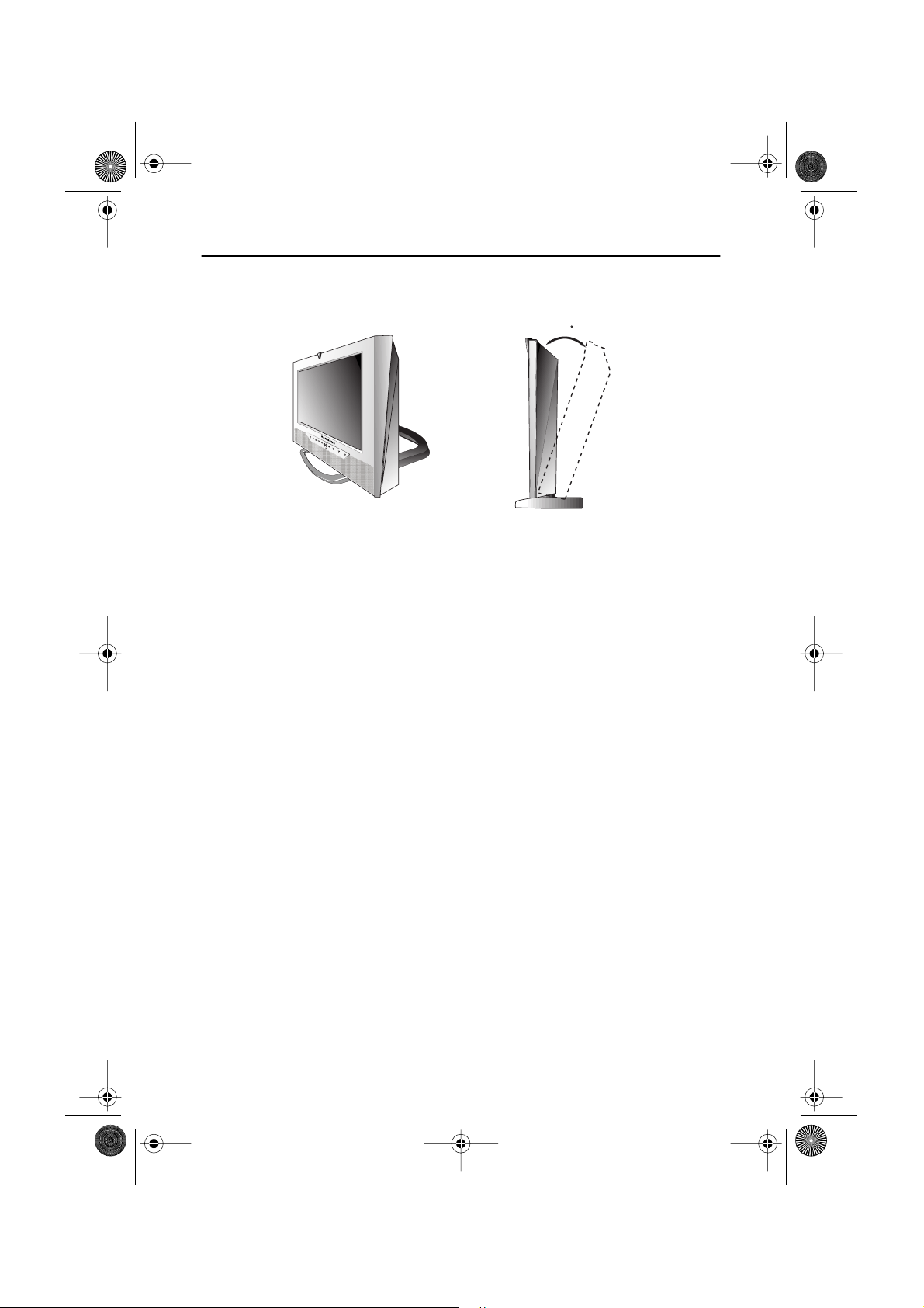
Retractable Stand
NOTE: The maximum tilt angle is 15 degree to the backward direction. Please do not
tilt the monitor other than specified range. Excessive force to tilt the
monitor other than specified range may give permanent damage to the
mechanical part of the stand.
Maintenance of Your LCD TV/Monitor
WARNING: To avoid risk of electric shock, do not disassemble the monitor cabinet (except
for gaining access to the cable connectors as described on page 5). Users cannot
service the monitor. User maintenance is restricted to cleaning as explained
below:
Unplug the monitor from the power outlet before cleaning.
To clean your flat panel display screen, lightly dampen a soft, clean cloth with
water or mild detergent. If possible, use a special screen cleaning tissue or
solution suitable for the antistatic coating.
To clean the monitor cabinet, use a cloth lightly dampened with a mild detergent.
Never use flammable cleaning material to clean your LCD monitor or any other
electrical apparatus.
English 35

7_LW15E13C-IX.fm Page 36 Friday, July 20, 2001 4:09 PM
Index
A
Active Area
Automatic Save
21
9
B
Bass 17
Brightness
Buzzer 13
14, 20
C
14, 20
5
Cable connections
CH
9
Channel Sort 20
Channel System 18
Coarse
15
Color 20
Contrast
D
DC adapter
Display Modes
Duration 13
3
31
E
Exit
10
F
Fine
15
Function icons 13, 14, 18
H
Halftone 13
H-position
17
I
Image lock
Image size
Information 15
Installation CD 3
15
16
K
Kensington security slot
L
Language 13
M
Manual Tune 19
Menu
10
MTS/S-Mode 23
O
ON-Screen Display 12
OSD Lock/Unlock 11
OSD Control 13
P
PAL Broadcasting System 32
Pan 16
Pin Assignments 30
PIP 9,17
Plug and Play 7
Power 9
Power Indicator 7
Power-saving modes 24
Program 11
R
Remote Controller 3, 22
Reset 15
S
S-VHS Cable 3
Safety Instructions
Scart Jack
Self-test feature check
Sharpness 20
Size 17
Sound Control 17, 20
Speaker mute 17
Stereo-RCA Cable 3
Stereo System 19
Store 20
2
3
7
T
Tilt the screen
Timer 21
Treble 17
Troubleshooting
4
TV Setup 18
U
User control locations 9
User mode 14
4
25
V
VOL 10
Volume
11
V-position
17
Z
Zoom 16
English 36

9_Re.fm Page 18 Friday, July 20, 2001 4:12 PM
Regulatory Information
FCC Information
User Instructions
The Federal Communications Commission Radio
Frequency Interference Statement includes the
following warning:
Note: This equipment has been tested and found to
comply with the limits for a Class B digital device,
pursuant to Part 15 of the FCC Rules. These limits are
designed to provide reasonable protection against
harmful interference in a residential installation. This
equipment generates, uses, and can radiate radio
frequency energy and, if not installed and used in
accordance with the instructions, may cause harmful
interference to radio communications. However, there
is no guarantee that interference will not occur in a
particular installation.
If this equipment does cause harmful interference to
radio or television receptions, which can be determined
by turning the equipment off and on, the user is
encouraged to try to correct the interference by one or
more of the following measures:
Reorient or relocate the receiving antenna.
Increase the separation between the equipment and
receiver.
Connect the equipment into an outlet on a circuit different from that to which the receiver is connected.
Consult the dealer or an experienced radio/TV technician for help.
User Information
Changes or modifications not expressly approved by the
party responsible for compliance could void the user’s
authority to operate the equipment.
If necessary, consult your dealer or an experienced
radio/television technician for additional suggestions.
You may find the booklet called How to Identify and
Resolve Radio/TV Interference Problems helpful. This
booklet was prepared by the Federal Communications
Commission. It is available from the U.S. Government
Printing Office, Washington, DC 20402, Stock Number
004-000-00345-4.
Warning
User must use shielded signal interface cables to
maintain FCC compliance for the product.
Declaration of conformity for products
Marked with FCC Logo
This device complies with Part 15 of the FCC Rules.
Operation is subject to the following two conditions: (1)
this device may not cause harmful interference, and (2)
this device must accept any interference received,
including interference that may cause undesired
operation.
The party responsible for product compliance:
SAMSUNG ELECTRONICS CO., LTD
America QA Lab of Samsung
85 West Tasman Drive
San Jose, CA 95134 USA
Tel) 408-544-5124
Fax) 408-544-5191
Provided with this monitor is a detachable power
supply cord with IEC320 style terminations. It may be
suitable for connection to any UL Listed personal
computer with similar configuration. Before making the
connection, make sure the voltage rating of the
computer convenience outlet is the same as the
monitor and that the ampere rating of the computer
convenience outlet is equal to or exceeds the monitor
voltage rating.
For 120 Volt applications, use only UL Listed detachable
power cord with NEMA configuration 5-15P type
(parallel blades) plug cap. For 240 Volt applications use
only UL Listed Detachable power supply cord with
NEMA configuration 6-15P type (tandem blades) plug
cap.
IC Compliance Notice
This Class B digital apparatus meets all requirements
of the Canadian Interference-Causing Equipment
Regulations of ICES-003.
Cet appareil Numérique de classe B respecte toutes les
exigences du Règlemont ICES-003 sur les équipements
produisant des interférences au Canada.
MPR II Compliance
This monitor complies with SWEDAC(MPR II)
recommendations for reduced electric and magnetic
fields.
European Notice
Products with the CE Marking comply with both the
EMC Directive (89/336/EEC), (92/31/EEC), (93/68/EEC)
and the Low Voltage Directive (73/23/EEC) issued by
the Commission of the European Community.
Compliance with these directives implies conformity to
the following European Norms:
EN55022:1998 – Radio Frequency Interference
EN55024:1998 – Electromagnetic Immunity
EN61000-3-2:1995 + A1 + A2 – Power Line Harmonics
EN61000-3-3:1995 – Voltage Fluctuations
EN60950 – Product Safety.
8_Ebk.fm Page 1 Wednesday, August 8, 2001 4:58 PM
U.S.A.:
Samsung Electronics America (SEA)
400 Valley Road, Suite 201
Mt. Arlington, NJ 07856
Tel.: 1-800-SAMSUNG (1-800-726-7864)
CANADA:
Samsung Electronics Canada Inc.
7037 Financial Drive
Mississauga, Ontario L5N 6R3
Tel.: 1-800-SAMSUNG (1-800-726-7864)
Fax.: (905) 542-1199
GERMANY:
Samsung Electronics GmbH
Samsung-Haus, Am Kronberger Hang 6
65824 Schwalbach/Ts.
Tel. 49 (0180) 5121213
Fax. 49 (0180) 5121214
DM 0,24/Min.
*
*
*
AUSTRALIA:
Samsung Electronics Australia Pty Ltd.
Unit G, 10-16 South Street,
Rydalmere, N.S.W. 2116
P.O. BOX 368
Tel.: (02) 638 5200
ITALIA:
Samsung Electronics Italia SpA
Via C. Donat Cattin,
5-20063 Cernusco sul Naviglio (Mi)
Tel.: 167-010740
PANAMA:
Servicios Samsung (Zona Libre), S.A.
50 and 61 Streets Sta, Cecilia
Bdl. Don Camilo, Panama City
Tel.: (507) 264-0195 or 269-5571
Fax: (507) 269-5568
MEXICO:
Samsung Electronics Mexico S.A. de C.V.
Saturno 44 Col. Nva. Industrial Vallejo
Del. Gustavo A. Madero C.P. 07700
Mexico D.F. Tel. 5747-5100
RFC: SEM950215S98
ESPAÑA:
Samsung Electrónics Comercial Ibérica, S.A. Ciencies, 5565 (Polígono Pedrosa) 08908 Hospitalet de Llobregat
(Barcelona)
Tel.: (93) 261 67 00
Fax.: (93) 261 67 50
UK:
Samsung Electronics (UK) Ltd.
Samsung House, 225 Hook Rise South
Surbiton, Surrey KT6 7LD
Tel.: (0181) 391 0168
Fax.: (0181) 397 9949
<European Service Center & National Service>
Stafford Park 12 Telford, Shropshire, TF3 3BJ
Tel.: (01952) 292 262
Fax.: (01952) 292 033
THAILAND:
Samsung Service Center
729-729/1 JSP Tower Rachadapisek RD.,
Bangpongpang, Yannawa, Bangkok 10120
Tel: (662) 2954508-14
Fax: (662) 2954267
SOUTH AFRICA:
Samsung Electronics South Africa
Somerset Office Park 5 Libertas Road
Bryanston, South Africa
Tel: (27)-11-463-5678
Fax: (27)-11-463-5215
BRASIL:
Samsung Eletrônica da Amazonia Ltda.
R. Prof. Manoelito de Ornellas, 303-2º Andar
Chácara Sto. Antônio • cep: 04719-040
São Paulo • SP
Tel.: (011) 541-8500
Fax: (011) 523-3995, 522-0726
SWEDEN:
Samsung Electronics Svenska, AB
Box 713, S-194 27 Upplands Vasby
Tel: (468) 590-966-00
Fax: (468) 590-966-50
IMPORTADO POR:SAMSUNG ELECTRONICS MEXICO S.A. DE C.V.
SATURNO 44 COL. NVA. INDUSTRIAL VALLEJO
DEL. GUSTAVO A. MADERO C.P. 07700
MEXICO D.F. TEL. 5747-5100
RFC: SEM950215S98
EXPORTADO POR: SAMSUNG ELECTRONICS CO.,LTD.
JOONG-ANG DAILY NEWS BLDG.
7 SOON-WHA-DONG CHUNG-KU,
C.P.O BOX 2775, 1144 SEOUL, KOREA
“As an E
determined that this product meets the
NERGY
E
®
NERGY
S
TAR
Partner, SAMSUNG has
®
S
TAR
guidelines for energy efficiency.”
P/N : BN68-00227A-02
Printed on recyclable paper
 Loading...