

Page 1

4 Alignments and Adjustments
4-1 General Alignment Instuction
1. Usually, a color TV-VCR needs only slight touch-up adjustment upon installation.
Check the basic characteristics such as height, horizontal and vertical sync.
2. Use the specified test equipment or its equivalent.
3. Correct impedance matching is essential.
4. Avoid overload. Excessive signal from a sweep generator might overload the front-end of the TV.
When inserting signal markers, do not allow the marker generator to distort test result.
5. Connect the TV only to an DC power source with voltage and frequency as specified on
the backcover nameplate.
6. Do not attempt to connect or disconnect any wire while the TV is turned on.
Make sure that the power cord is disconnected before replacing any parts.
7. To protect aganist shock hazard, use an isolation transform.
LW15M23C 4-1
Page 2
4 Alignments and Adjustments
1. Calibration
1. Calibration
VCTi
PC
2. Option 1. Video Mute O
2. Auto Power On
3. Panel XGA
4. Inch 15
5. Antenna Osd off
6. TTX List/FloF FloF
7. Auto FM On
8. ACC/ACM O
9. Gamma LUT O
10. ESM On
11. System CW
2. Option
3. W/B
4. ADC
5. VCTi 0000
6. ACC/ACM
7. Test Pattern 0
8. Bus Stop off
9. Check Sum 0
10. Reset
T- VNCNEU - 0007 2004/03/02
4-2 Factory Mode Adjustments
4-2-1 Entering Factory Mode
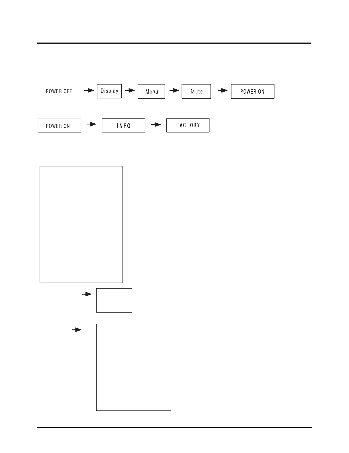
1. To enter “Service Mode” Press the remote -control keys in this sequence :
- If you do not have Factory remote - control
- If you have Factory remote - control
4-2-2 Factory Mode Tree
4-2 LW15M23C
Page 3

4 Alignments and Adjustments
3. W/B(1)
3. W/B(2)
R level 128
G level 128
B level 128
R gain 127
G gain 127
B gain 127
g Sub Color 0
g Sub Tint 50
Recall
RF RF
[I nit ial Dat a] [Ad just Dat a]
RemarkAdjustment item
Item
Cannot be adjustment
Adjustment
External input
External input
External input
External input
Cannot be adjustment
Cannot be adjustment
Cannot be adjustment
Cannot be adjustment
Cannot be adjustment
Red level ADJ [ 0~255] 128 128
Blue le
vel
128 F IXGreen level A DJ[ 0~255] 128 128
Blue level F IX [0~255] 128 128
Red Gain F I X [ 0~255] 128 135
Red Gain 135 FI X
`
Green Gain ADJ [ 0~255] 128 135
Blue Gain A DJ[ 0~255] 128 135
gSUB Color F IX [0~255] 0 0
gSUB Tint F IX [0~255] 50 50
F actor y Recal l
*A/S : Micom Initial Data Write
Dy namic RemarkCool 1
MODE RF[ADJ] COM PONENT 480i COM PONENT 480P PC
* W/B connot be
adjusted in
COMPONENT &PC
* Only x,y axes can
be adusted in
High & Low Light
Signal Source
ABL Patter
Process
n
[M SPG925LT H]
ABL Pattern
[M SPG925L T H]
ABL Pattern
[M SPG925L T H]
ABL Pattern
[M SPG925L TH ]
W/B
SPE C
High
x=270 2, y=270 2
Low
x=270 2, y=270 2
W/B
SPEC
High
x=270 10, y=270 10 , Y=22. 0 [ FL] x =270 20, y=270 20 x=270 20, y=275 20 x=250 30, y=260 30
Low
x=27010,y=27010,Y=0.30.1[FL] x =260 20, y=260 20 x=280 20, y=290 20 x=250 30, y=255 30
+_
+_
+_
+_
+_
+_
+_+_
+_
+_
+_+_
+_
+_
+_+_
+_+_
+_
+_
LW15M23C 4-3
Page 4

4 Alignments and Adjustments
4. ADC
R offset
VCTi
53
G offset
43
B offset
47
R gain 0
125
R gain 1
1
G gain 0
122
G gain 1
1
B gain 0
134
B gain 1
1
R offset
PC
66
G offset
63
B offset
51
R gain 0
54
R gain 1
1
G gain 0
62
G gain 1
1
B gain 0
66
B gain 1
1
5. VCTi
R Drive
192
G Drive
192
B Drive
192
Sub Contrast
56
Sub Bright
128
Sub Sharp
10
Sub Color
0
Sub Tint
50
Sub Coring
20
RF AGC
2
Vpeaking
6
CTI Gain
15
CTI Coring
5
LMIXOFS
2
PKCF
3
AGCADJ1
43
LTI Gain
15
6. ACC/ ACM
Y Max D
7
Y Scl Thr
64
Y Scl A
5
Y Scl B
0
A Ctrl
0
A Snslp
8
T Dixel
12
Lower End
80
Mid Start
30
Mid End
100
Up Stant
40
Low Sn Thr
60
Up Sn Thr
0
Y Min
10
Y Max
255
Ym Div Slp
128
Fr Age
1
Fr App
0
Esm Ctrl
127
4-4 LW15M23C
Page 5

7. Test Pattern ( Test Pattern of VCTi)
1) VCTi
2) Toshiba
3) Gray Bar
4) Gray
5) Green
6) Color Bar
7) Cross
8. Bus Stop
- Bus stop is used data communication.
9. Chcek Sum
- Display the current check sum size of the MICOM.
4 Alignments and Adjustments
10. Reset
- Initializes the data in the MICOM.
11. T-VNCNEU-0007 2004/03/02
- Display the MICOM program version.
4-2-3 White Balance
High Low
285, 295 285, 295
x, y x, y
LW15M23C 4-5
Page 6

4 Alignments and Adjustments
Memo
4-6 LW15M23C
 Loading...