

Samsung LTY[Z]460HB01, LTY460HB01 Technical Specifications
1/ 31Page05-000-S-070907Doc. NoLTY[Z]460HB01MODEL
Customer : SONY DATE : 07 Sep. 2007
DATE
SIGNATURE
Customer
Customer’’
s Approval
s Approval
DATE
07 Sep,2007
DATE
07 Sep,2007
PREPARED BY
APPROVAED BY
Any Modification of Specification is not allowed without SEC's Permission.
NOTE :
Approval
Approval
SAMSUNG TFT-LCD
MODEL : LTY[Z]460HB01
SAMSUNG TFT
SAMSUNG TFT--
LCD
LCD
MODEL
MODEL
: LTY[Z]460HB01
: LTY[Z]460HB01
SL Development Team, LCD Business
Samsung Electronics Co . , LTD.
2/ 31Page05-000-S-070907Doc. NoLTY[Z]460HB01MODEL
Contents
Revision History -------------------------------------------------------------------------------------------- (3)
General Description --------------------------------------------------------------------------------------- (4)
General Information --------------------------------------------------------------------------------------- (4)
1. Absolute Maximum Ratings -------------------------------------------------------------------------- (5)
2. Optical Characteristics --------------------------------------------------------------------------------- (6)
3. Electrical Characteristics ------------------------------------------------------------------------------- (9)
3.1 TFT LCD Module
3.2 Back Light Unit
4. Block Diagram ------------------------------------------------------------------------------------------- (11)
5. Input Terminal Pin Assignment --------------------------------------------------------------------- (12)
5.1 Input Signal & Power
5.2 Balance Board
5.3 LVDS Interface
5.4 Input Signals, Basic Display Colors and Gray Scale of Each Color
6. Interface Timing ---------------------------------------------------------------------------------------- (20)
6.1 Timing Parameters (DE only mode)
6.2 Timing Diagrams of interface Signal (DE only mode)
6.3 Power ON/OFF Sequence
7. Outline Dimension -------------------------------------------------------------------------------------- (23)
8. EMI Specification --------------------------------------------------------------------------------------- (25)
9. Spread Spectrum Specification
10. UL Approval
11. Reliability Test ----------------------------------------------------------------------------------------- (26)
12. Packing ------------------------------------------------------------------------------------------------ (27)
13. Marking & Others ------------------------------------------------------------------------------------- (28)
14. General Precaution ---------------------------------------------------------------------------------- (29)
14.1 Handling
14.2 Storage
14.3 Operation
14.4 Operation Condition Guide
14.5 Others
3/ 31Page05-000-S-070907Doc. NoLTY[Z]460HB01MODEL
* Revision History
First Issued-000
Sep.
07,
2007
SummaryPage
Rev.
No
Date
4/ 31Page05-000-S-070907Doc. NoLTY[Z]460HB01MODEL
LTY[Z]460HB01 is a color active matrix liquid crystal display (LCD) that uses amorphous
silicon TFT(Thin Film Transistor) as switching components. This model is composed of a
TFT LCD panel, a driver circuit and a back light unit. The resolution of a 46.0“ is 1920 x
1080 and this model can display up to 1.07 billion colors with wide viewing angle of 89° or
higher in all directions. This panel is intended to support applications to provide a excellent
performance for Flat Panel Display such as Home-alone Multimedia TFT-LCD TV, Display
terminals for AV application products, and High Definition TV (HDTV).
RoHS compliance (Pb-free)
1.07(True-10Bit) Color Support
High contrast ratio, high aperture ratio, fast response time
SPVA (Super Patterned Vertical Align) mode
Wide viewing angle (±89°)
High speed response
Full HD(1920 x 1080 pixels) resolution (16:9)
Low Power consumption
24 High color gamut CCFTs (Cold Cathode Fluorescent Tube)
DE(Data Enable) mode
Mini-LVDS (Mini Low Voltage Differential Signaling) interface
Features
General Description
Description
General Information
57.1(D
MAX
)
mm0.53025(H) x 0.17675(W)*3Pixel Pitch
g16000(Max)Weight
±1.0mm
mm
1083.0(H
TYP
) x 627.0(V
TYP
)
Module Size
mm1018.08(H) x 572.67(V)Active Display Area
Refer to Page 6
Note
DSLR(3H)Surface Treatment
cd/m
2
550Luminance of White
Normally BlackDisplay Mode
RGB vertical stripePixel Arrangement
pixel1920 x 1080Number of Pixels
colors1.07 billion(True-10Bit)Display Colors
UnitSpecificationItems
5/ 31Page05-000-S-070907Doc. NoLTY[Z]460HB01MODEL
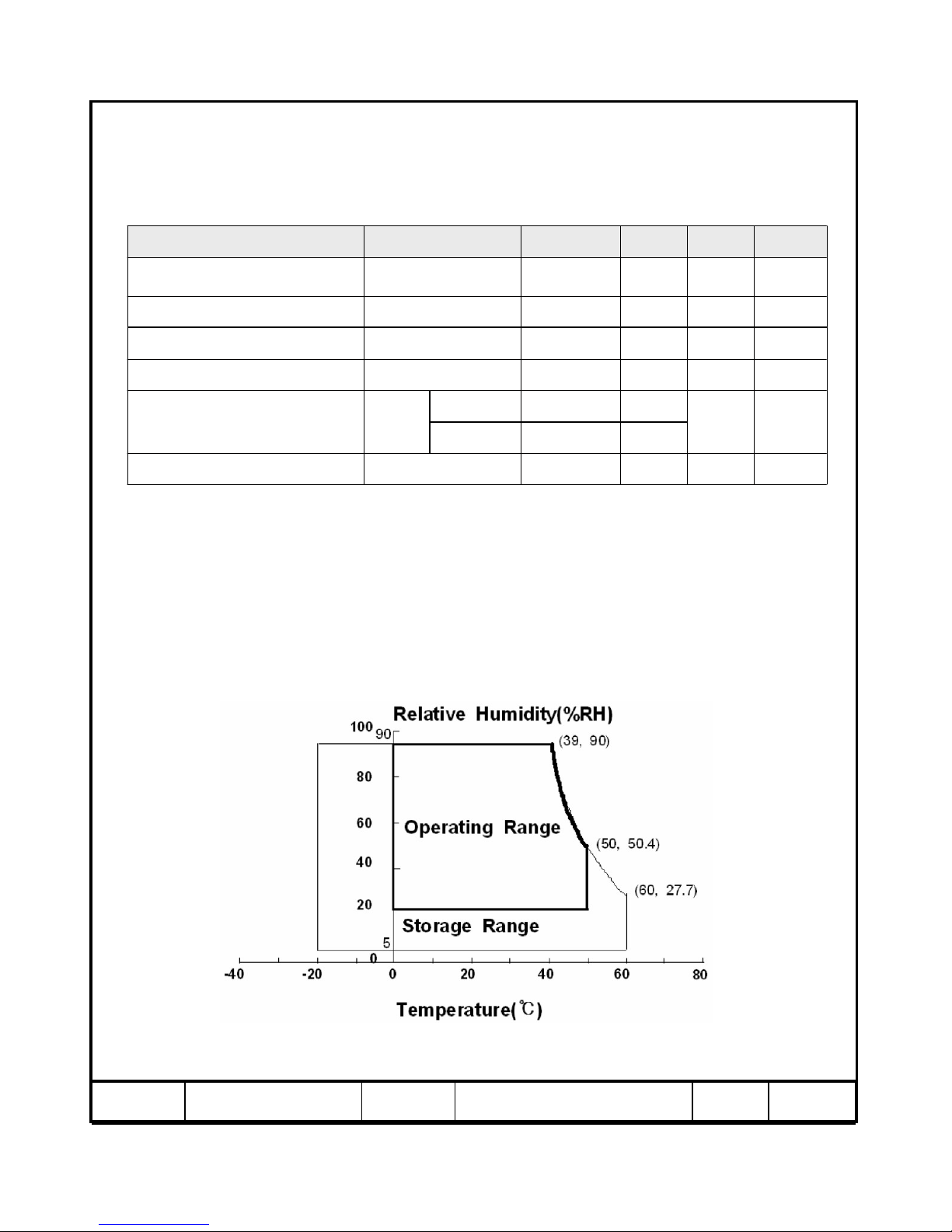
Note (1) Ta= 25 ± 2 °C
(2) Temperature and relative humidity range are shown in the figure below.
a. 93.8 % RH Max. (Ta ≤ 40 °C)
b. Maximum wet-bulb temperature at 40 °C or less. (Ta ≤ 40 °C)
c. No condensation
(3) Polarizer will not be damaged in this range, even though abnormal visual problems occur
in
T
SUR
range.
(4) 11ms, sine wave, one time for ±X, ±Y, ±Z axis
(5) 10-300 Hz, Sweep rate 10min, 30min for X,Y,Z axis
1. Absolute Maximum Ratings
If the condition exceeds maximum ratings, it can cause malfunction or unrecoverable
damage to the device.
Fig. Temperature and Relative humidity range
30-
±Z axis
±XY axis
(2)
℃
500T
OPR
Operating Temperature
40
(1)V13GND-0.5V
DD
Power Supply Voltage
(5)G1.5-V
NOP
Vibration ( non - operating )
(4)G
-
S
NOP
Shock ( non - operating )
(3)
℃
650T
SUR
Panel surface temperature
(2)
℃
65-20T
STG
Storage temperature
NoteUnitMax.Min.SymbolItem
6/ 31Page05-000-S-070907Doc. NoLTY[Z]460HB01MODEL
2. Optical Characteristics
The optical characteristics should be measured in a dark room or equivalent.
Measuring equipment : TOPCON BM-7,SPECTRORADIOMETER SR-3
(Ta = 25 ± 2°C, VDD=12V, fv= 60Hz, f
DCLK
=148.5MHz, Dim = 90%)
-2.2-
γ
Gamma
-8-
Normal
θL,R=0
θU,D=0
Viewing
Angle
TgG-to-G
(7)
SR-3
%-90--Color Gamut
Ver.
Hor.
(4)
SR-3
%23--B
uni
Brightness Uniformity
(9 Points)
-8979θ
D
-8979θ
U
-8979θ
R
(8)
SR-3
Degree
-8979
C/R≥10
θ
L
Viewing
Angle
(7)
SR-3
K-(11800)*--Color Temperature
White
Blue
Green
Red
Falling
Rising
(0.274)*Wy
(0.274)*Wx
(0.059)*By
(0.148)*Bx
(0.662)*Gy
(0.211)*Gx
(0.324)*Ry
(7),(8)
SR-3
TYP.
+0.03
(0.651)*
TYP.
-0.03
Rx
Color
Chromaticity
(CIE 1931)
(6)
SR-3
cd/m
2
-550450Y
L
Luminance of White
(Center of screen)
106-Tf
(5)
BM-7
msec
1610-Tr
Response
Time
(3)
SR-3
-1700(1000)*C/R
Contrast Ratio
(Center of screen)
NoteUnitMax.Typ.Min.ConditionSymbolItem
Note (1) Test Equipment Setup
The measurement should be executed in a stable, windless and dark room between
40min and 60min after lighting the back light at the given temperature for stabilization
of the back light. This should be measured in the center of screen.
Single lamp current @ I
L
= 6.5mArms(typ.), Dim = 90%
Environment condition : Ta = 25 ± 2 °C
* marked Items will be decided after taking data of early mass production.

7/ 31Page05-000-S-070907Doc. NoLTY[Z]460HB01MODEL
2°BM-7
1°SR-3
Field Photo detector
Photo detector
LCD Panel
TFT - LCD Module
The center of the screen
SR-3 : 50㎝
BM-7 : 50㎝
Field
Note (2) Definition of test point
①②③
⑥
⑨
⑧
⑤④
⑦
Active Area
Test Point
Note (3) Definition of Contrast Ratio (C/R)
: Ratio of gray max (Gmax) & gray min (Gmin) at the center point ⑤ of the panel
CR
G
G
/
max
min
=
Gmax : Luminance with all pixels white
Gmin : Luminance with all pixels black
320 960 1600
900
540
180
8/ 31Page05-000-S-070907Doc. NoLTY[Z]460HB01MODEL
Note (4) Definition of 9 points brightness uniformity
Note (5) Definition of Response time : Sum of Tr, Tf
Buni
BB
B
=∗
−
100
(max min)
max
Bmax : Maximum brightness
Bmin : Minimum brightness
Display data
Optical Instruments
Response
TIME
T
R
T
F
10%
90%
White (data off)
0%
Black (data off)
White (data on)
100%
Note (6) Definition of Luminance of White : Luminance of white at center point ⑤
Note (7) Definition of Color Chromaticity (CIE 1931)
Color coordinate of Red, Green, Blue & White at center point ⑤
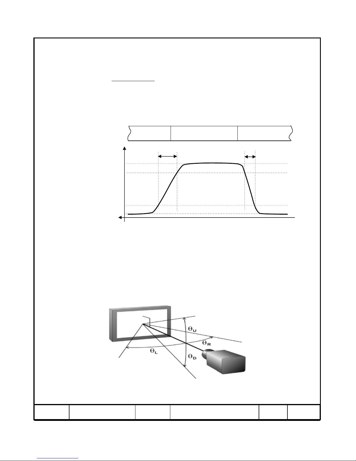
Note (8) Definition of Viewing Angle
: Viewing angle range (C/R ≥10)
9/ 31Page05-000-S-070907Doc. NoLTY[Z]460HB01MODEL
3. Electrical Characteristics
3.1 TFT LCD Module
The connector for display data & timing signal should be connected.
Ta = 25°C ± 2 °C
(4)A3--I
RUSH
Rush Current
MHz155148.5130f
DCLK
Main Frequency
kHz7567.550f
H
Hsync Frequency
Hz636047f
V
Vsync Frequency
mA-1000-(c) Mosaic
mA13001200-(b) White
(2),(3)
mA-800-
I
DD
(a) Black
Current
of Power
Supply
(1)V131211V
DD
Voltage of Power Supply
NoteUnitMax.Typ.Min.SymbolItem
Note (1) The ripple voltage should be controlled under 10% of VDD.
(2) f
V=60Hz, fDCLK = 148.5MHz, V
DD
= 12.0V, DC Current.
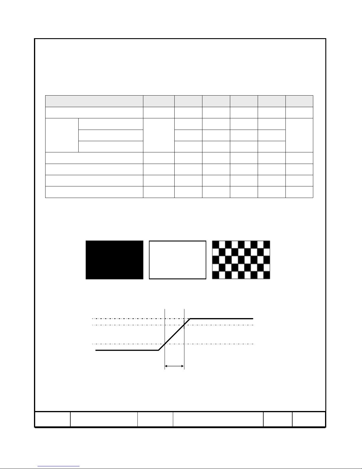
(3) Power dissipation check pattern (LCD Module only)
a) Black Pattern b) White Pattern c) Mosaic
(4) Measurement Conditions
Rush Current I
RUSH
can be measured when T
RUSH
. is 1ms.
T
RUSH
=1ms
100%
GND
90%
10%
V
DD
10 / 31Page05-000-S-070907Doc. NoLTY[Z]460HB01MODEL
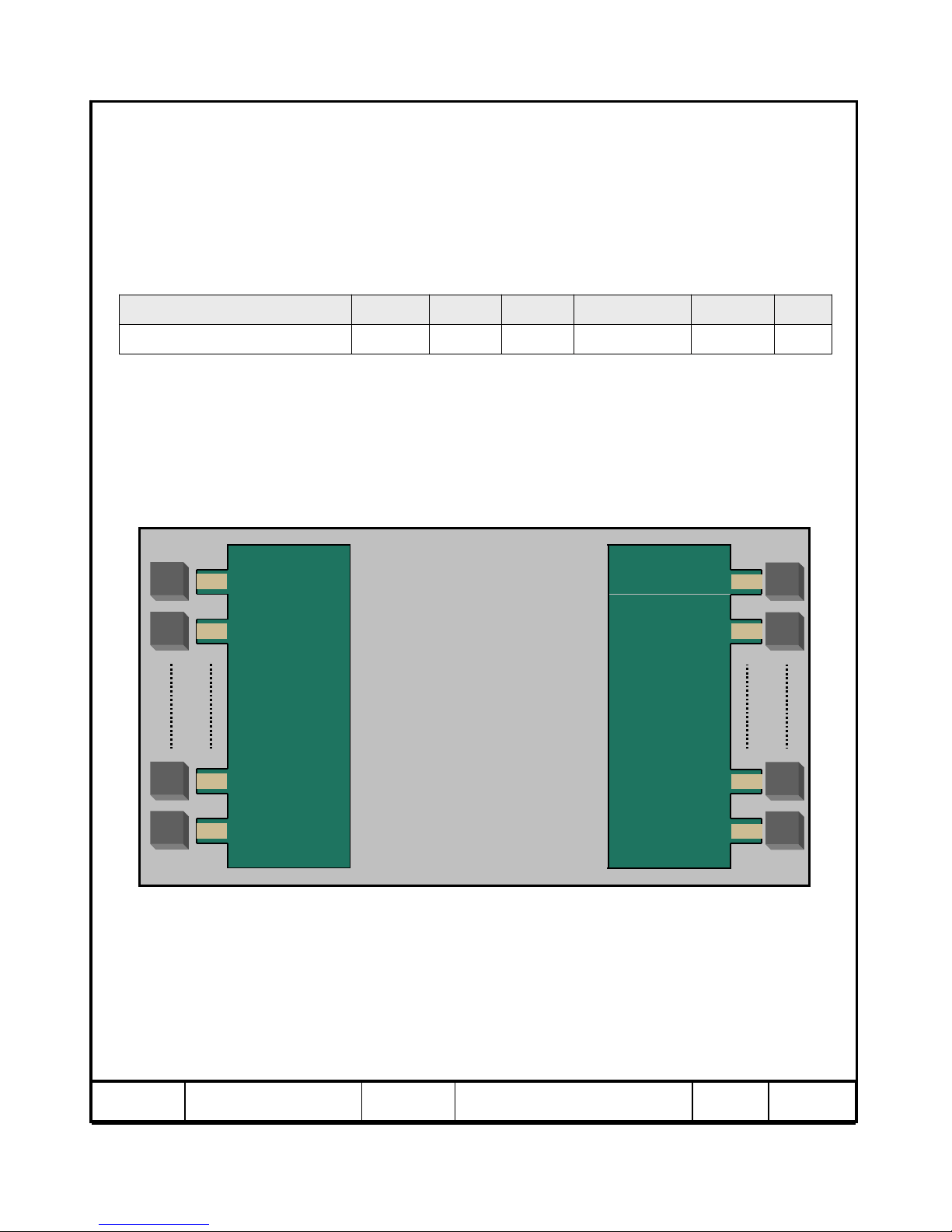
3.2 Back Light Unit
The back light unit contains 24 CCFTs ( Cold Cathode Fluorescent Tube ).
The characteristics of lamps are shown in the following tables.
Ta=25 ± 2°C
(1)Hour--30,000HrOperating Life Time
NoteUnitMax.Typ.Min.SymbolItem
Note (1) It is defined as the time to take until the brightness reduces to 50% of its original value.
[Operating condition : Ta = 25±2℃, I
L
=6.5mArms(typ.), For single lamp only. ]
LCD
Module
Socket
Balance
Board
HOT 1
HOT 2
HOT 23
HOT 24
Balance
Board
HOT 24
HOT 23
HOT 2
HOT 1
Socket
 Loading...