

Page 1
English-1
YOUR NEW TV
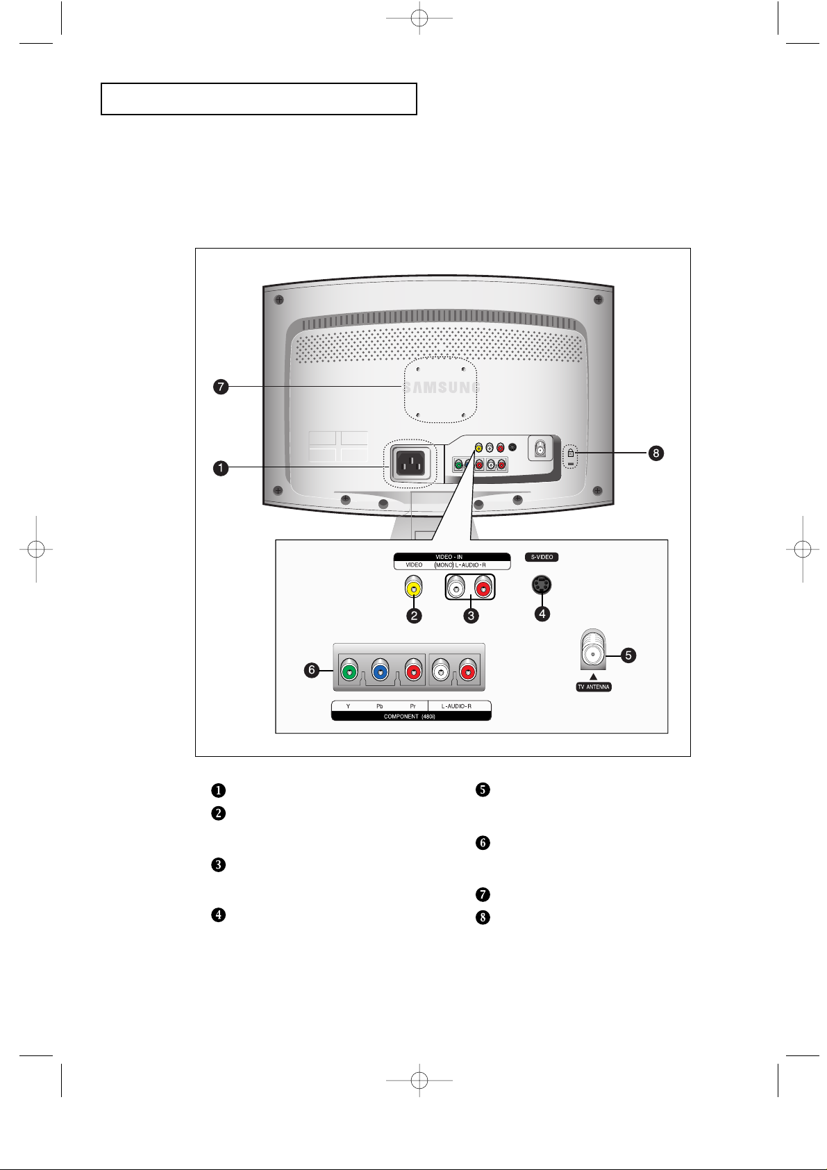
Rear Panel Jacks
Use the rear panel jacks to connect an A/V component that will be connected
continuously, such as a VCR or a DVD player.
POWER INPUT
VIDEO INPUT
Connect a video signal from a
camcorder or VCR.
AUDIO INPUT
Connect audio signal from a
camcorder or VCR.
SUPER VIDEO INPUT
Connect S-Video signal from a
camcorder or VCR.
TV ANTENNA
Connect to an antenna or to a cable
TV system.
COMPONENT
Connect component video/audio from
a DVD player.(only 480i)
WALL MOUNT HOLES
KENSINGTON LOCK
01-12_EN 1/9/04 8:02 PM Page 3
Page 2
English-2
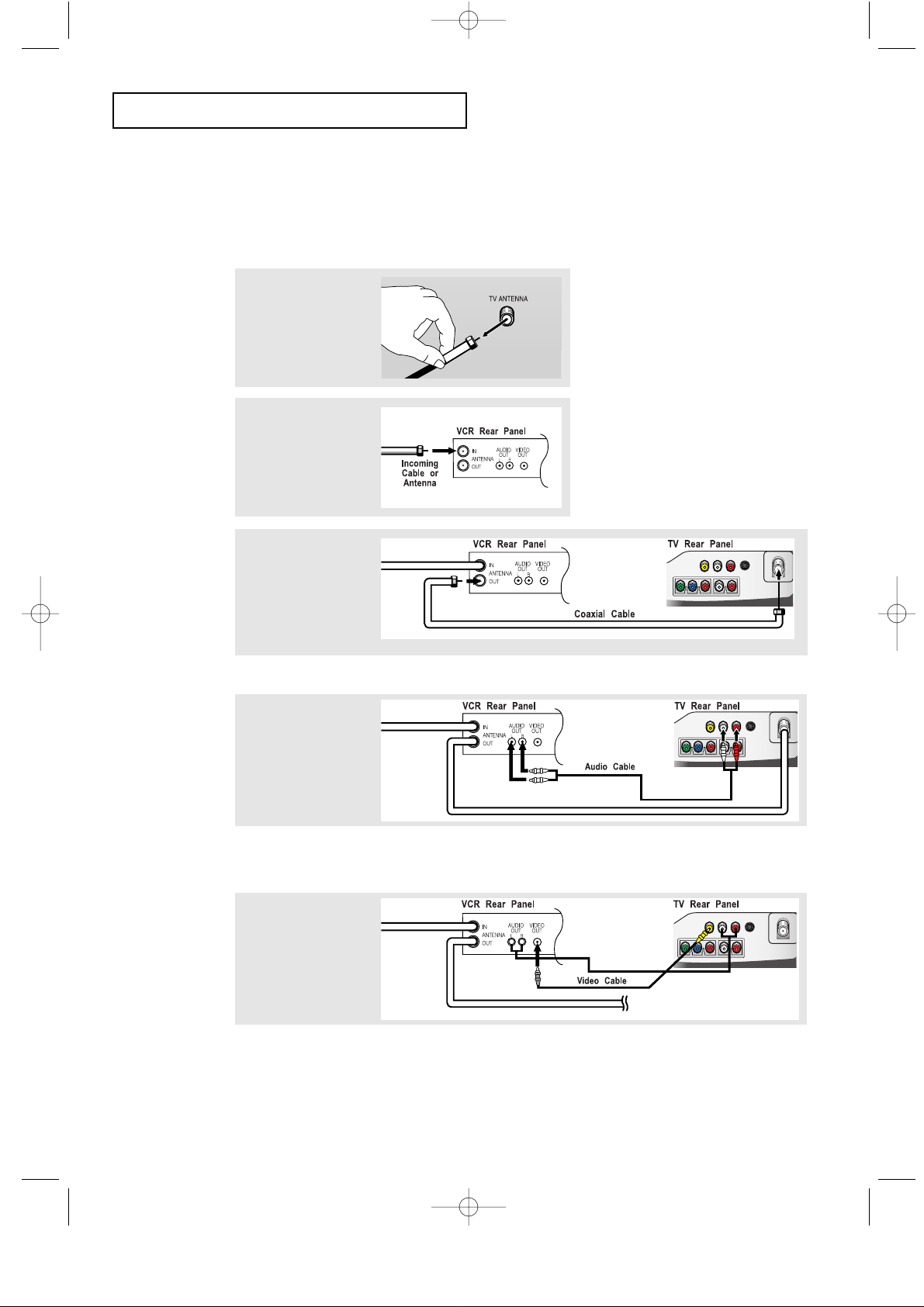
INSTALLATION
3
Connect a coaxial
cable between the
ANTENNA OUT
terminal on the VCR
and the antenna
terminal on the TV.
4
Connect a set of
audio cables
between the AUDIO
OUT jacks on the
VCR and the AUDIO
jacks on the TV.
5
Connect a video
cable between the
VIDEO OUT jack on
the VCR and the
VIDEO jack on the
TV.
Follow the instructions in “Viewing a VCR or Camcorder Tape” to view your VCR tape.
# Each external input source device has a different back panel configuration.
A coaxial cable is usually included with a VCR. (If not, check your local electronics store).
If you have a “mono” (non-stereo) VCR, use the Y-connector (not supplied) to hook up
to the left and right audio input jacks of the TV. If your VCR is stereo, you must
connect two cables.
Connecting a VCR
These instructions assume that you have already connected your TV to an antenna or a
cable TV system .
Skip step 1 if you have not yet connected to an antenna or a cable system.
1
Unplug the cable or
antenna from the
back of the TV.
2
Connect the cable
or antenna to the
ANTENNA IN terminal
on the back of the
VCR.
01-12_EN 1/9/04 8:02 PM Page 10
Page 3
English-3
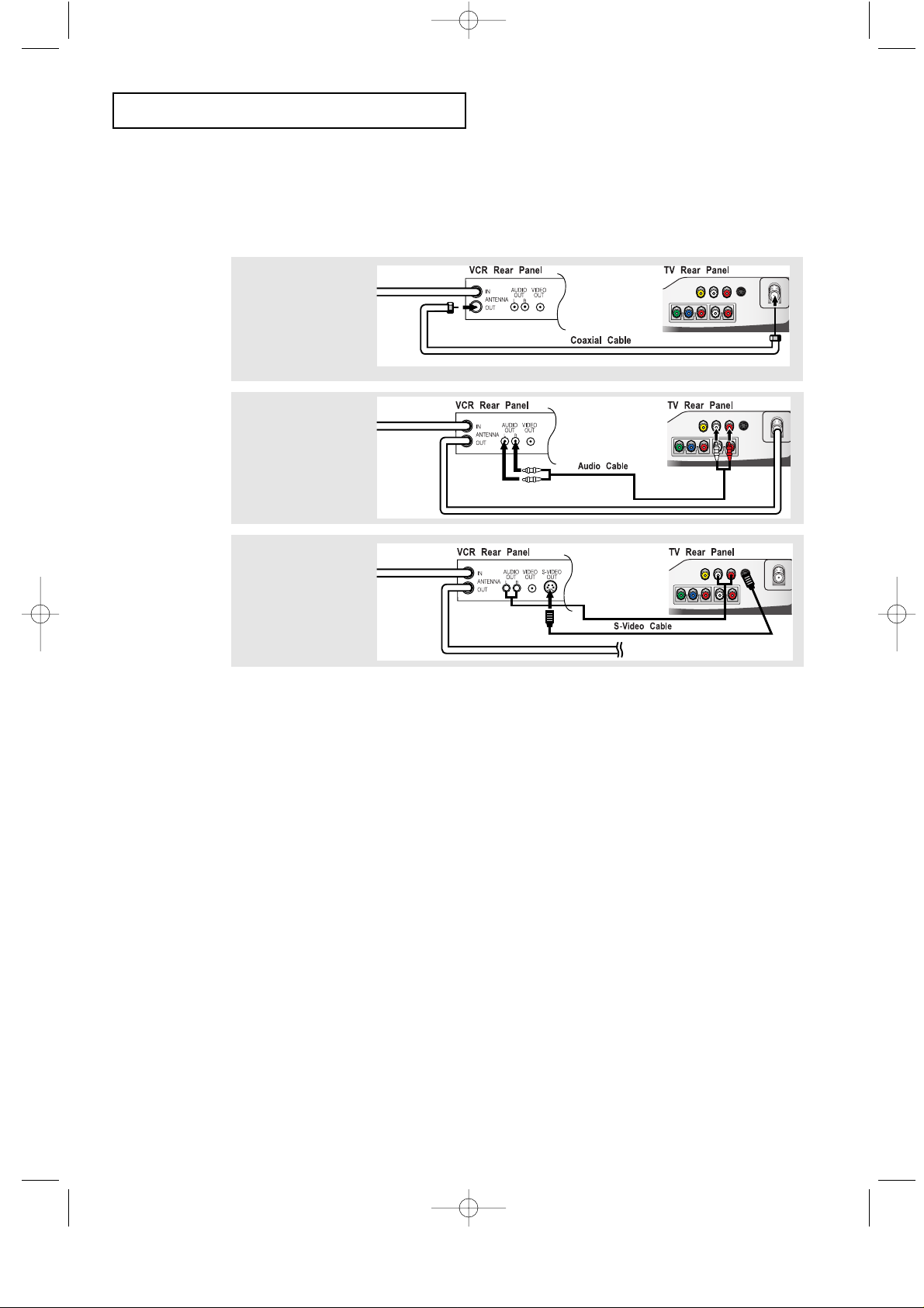
INSTALLATION
3
Connect an S-video
cable between the
S-VIDEO OUT jack on
the VCR and the
S-VIDEO INPUT jack
on the TV.
An S-video cable is usually included with an S-VHS VCR.
(If not, check your local electronics store.)
# Each external input source device has a different back panel configuration.
1
To begin, follow
steps 1–3 in the
previous section to
connect the antenna
or cable to your
VCR and your TV.
Connecting an S-VHS VCR
Your Samsung TV can be connected to an S-Video signal from an S-VHS VCR.
(This connection delivers a better picture as compared to a standard VHS VCR.)
2
Connect a set of audio
cables between the
AUDIO OUT jacks on
the VCR and the
AUDIO INPUT jacks
on the TV.
01-12_EN 1/9/04 8:02 PM Page 11
Page 4

English-4
INSTALLATION
Note: For an explanation of Component video, see your DVD player owner's manual.
The Component input on the TV is 480i only.
# Each external input source device has a different back panel configuration.
Connecting a DVD Player
The rear panel jacks on your TV make it easy to connect a DVD player to your TV.
1
Connect a set of audio
cables between the
L, R AUDIO INPUT
jacks on the TV and
the AUDIO OUT jacks
on the DVD player.
2
Connect a video
cable between the
COMPONENT
(Y, Pb, Pr) jacks on
the TV and the Y, Pb,
Pr jacks on the DVD
player.
01-12_EN 1/9/04 8:02 PM Page 12
Page 5

English-5
Attaching a Wall or Arm mounting device
The TV supports VESA mounting standard for use with various VESA mounting
devices. To install any VESA mounting device, please follow the instructions given.
<A> <B>
1
Lay the LCD TV face-down on a flat surface with a cushion or other soft materials
to protect the screen.
2
Remove all cables connected on the TV.
3
Remove the four screws and then remove the Stand from the LCD TV. (refer to pictures A&B).
4
Re-connect all cables you removed in step 2.
5
Now you are ready to install Wall/Arm mounting device .
Maintenance of Your LCD TV
WARNING: To avoid risk of electric shock, do not disassemble the TV cabinet.
Users cannot service the TV.
User maintenance is restricted to cleaning as explained below:
Unplug the monitor from the power outlet before cleaning.
• To clean your flat panel display screen, lightly dampen a soft, clean cloth with water or mild
detergent. If possible, use a special screen cleaning tissue or solution suitable for the antistatic
coating.
• To clean the monitor cabinet, use a cloth lightly dampened with a mild detergent.
• Never use flammable cleaning material to clean your LCD TV or any other electrical apparatus.
39-43_EN 1/9/04 8:04 PM Page 39
Page 6

English-6
Installing VESA compliant mounting devices
Refer to previous page to remove the base.
Rear cover
Mounting pad
Align the mounting interface pad with the holes in the rear cover mounting pad and secure it with
the four screws that come with the arm-type base, wall mount hanger or other bases.
Wall Mount Instructions
The following instructions apply to a hollow sheet-rock wall only. Tools/Hardware needed - Philips
screwdriver, four toggle bolts, 5/8in dia. Drill bit and drill. Contact Ergotron at (800) 888-8458 to
purchase the triple pivot direct mount adapter and wall mount bracket kit.
• LTN1535 (15") : No. 47 - 007 - 099 (Pivot direct mount adapter)
No. 97 - 101 - 003 (Wall mount bracket kit)
• LTN1735 (17") : No. 47 - 007 - 099 (Pivot direct mount adapter)
No. 97 - 101 - 003 (Wall mount bracket kit)
• LTP2035 (20") : No. 47 - 007 - 099 (Pivot direct mount adapter)
No. 97 - 101 - 003 (Wall mount bracket kit)
Align the wall mount bracket on the wall at the desired height, making sure that the bracket will be
mounted between the wall studs. Mark the four corner openings and drill four 5/8-diameter holes.
Assemble the wall mount kit according to the instructions provided with it. Securely attach
Ergotron’s flat panel, triple pivot direct mount adapter to the back of the TV using the four 4mm,
.7 pitch x 10mm screws provided with the arm. Secure the assembly to the wall using four 3/16 by
3-inch long toggle bolts.
39-43_EN 1/9/04 8:04 PM Page 40
Page 7

English-7
APPENDIX
Using the Anti-Theft Kensington Lock
Retractable Stand
Note: The maximum tilt angle is 13 degrees in the backward direction.
Please do not tilt the TV outside the specified range. Using excessive force
to tilt the TV may cause permanent damage to the mechanical part of the stand.
Figure 2
Figure 1
Cable
The Kensington lock is a device used to physically fix the system when using it in a public place. The locking
device has to be purchased separately. The appearance and locking method may differ from the illustration
depending on the manufacturer. Please refer to the manual provided with the Kensington lock for proper use.
1
Insert the locking device into the Kensington slot on the LCD TV (Figure 1),
and turn it in the locking direction (Figure 2).
2
Connect the Kensington lock cable.
3
Fix the Kensington lock to a desk or a heavy stationary object.
<Optional>
39-43_EN 1/9/04 8:04 PM Page 41
 Loading...