

Page 1
CUSTOMER
G/A Customer
MODEL NO.
LTI820HA01
DATE OF ISSUE
2013/08/20
EXTENSION CODE
-0
Customer Approval & Feedback
Approved by
2013/08/20
Prepared by
2013/08/20
LCD Sales & Marketing Center
Samsung Display Co., Ltd
For eyes of Goodview Only
Product Specification
( ) Product Information
( ) Preliminary Specification
( √ ) Approval Specification
Any modification of Spec is not allowed without SDC’s permission.
Page 2

REVISION HISTORY ………………………………………………………………………………………………………..
3
GENERAL DESCRIPTION ……………………………………………………………………………………………….…
4
1. ABSOLUTE MAXIMUM RATINGS
1.1 ENVIRONMENTAL ABSOLUTE RATINGS …………………………………………………………..…
6
1.2 ELECTRICAL ABSOLUTE RATINGS …………………………………………………………………..….
7
1.3 THE OTHERS ABSOLUTE RATINGS ..………………………………………………………………..….
7
2. APPLICATION INFORMATION FOR DID(DIGITAL INFORMATION DISPLAY) ...…………………..……
8
3. OPTICAL CHARACTERISTICS …………………………………..…………………………………………………….
9
4. ELECTRICAL CHARACTERISTICS
4.1 TFT LCD MODULE ………………………………..………………………………………………………….
12
4.2 BACKLIGHT UNIT ……………………………...……………………………………………………………
13
4.3 LED CONVERTER CHARACTERISTICS .....………………………………………………………………
14
5. INPUT TERMINAL PIN ASSIGNMENT
5.1 INPUT SIGNAL & POWER ………………………………………………………………………………...
15
5.2 LED CONVERTER INPUT PIN CONFIGURATION ....…………………………………....................
17
5.3 LED CONVERTER POWER SEQUENCE ...……………………………………………………………….
17
5.4 LVDS INTERFACE …………………………………………………………………………………………....
18
5.5 INPUT SIGNALS, BASIC DISPLAY COLORS AND GRAY SCALE ……………………………..…..
19
6. INTERFACE TIMING
6.1 TIMING PARAMETERS (DE ONLY MODE) ………………………………………………......…….....
20
6.2 TIMING DIAGRAMS OF INTERFACE SIGNAL (DE ONLY MODE) ……………………………….
21
6.3 CHARACTERISTICS OF INPUT DATA OF LVDS ……………………………………………………...
22
6.4 THE SEQUENCE OF POWER ON AND OFF …………………………………………………………....
24
7. OUTLINE DIMENSION ………………………………………………………………………………………………....
24
8. RELIABILITY TEST .....................................................................................................................................
27
9. PACKING …………………………………………………………………………………………………………………..
28
10. MARKINGS & OTHERS ..……………………………………………………………………………………….........
29
11. GENERAL PRECAUTIONS …………………………………………………………………………………………....
30
For eyes of Goodview Only
————————————————————————————————————————————————
Table of Contents
——————————————————————————————————————————————––—
Doc.No. LTI820HA01-0 Page 2 of 32 Rev.No. 06-001-G-130820
Page 3
Date.
Rev.No.
Page
Revision Description
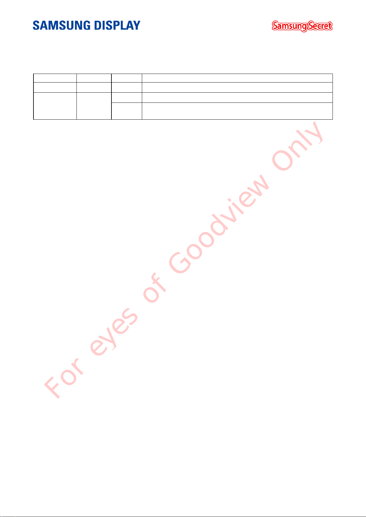
2013/07/30
000
all
Approval Spec Firstly issued
2013/08/20
001
7
Add the “THE OTHERS ABSOLUTE RATINGS”
28
Acceptance number of piling : 1Pallets
Move – 1Pallets / Stock – 2Pallets
For eyes of Goodview Only
————————————————————————————————————————————————
REVISION HISTORY
——————————————————————————————————————————————––—
Doc.No. LTI820HA01-0 Page 3 of 32 Rev.No. 06-001-G-130820
Page 4
Item
Specification
Unit
Note
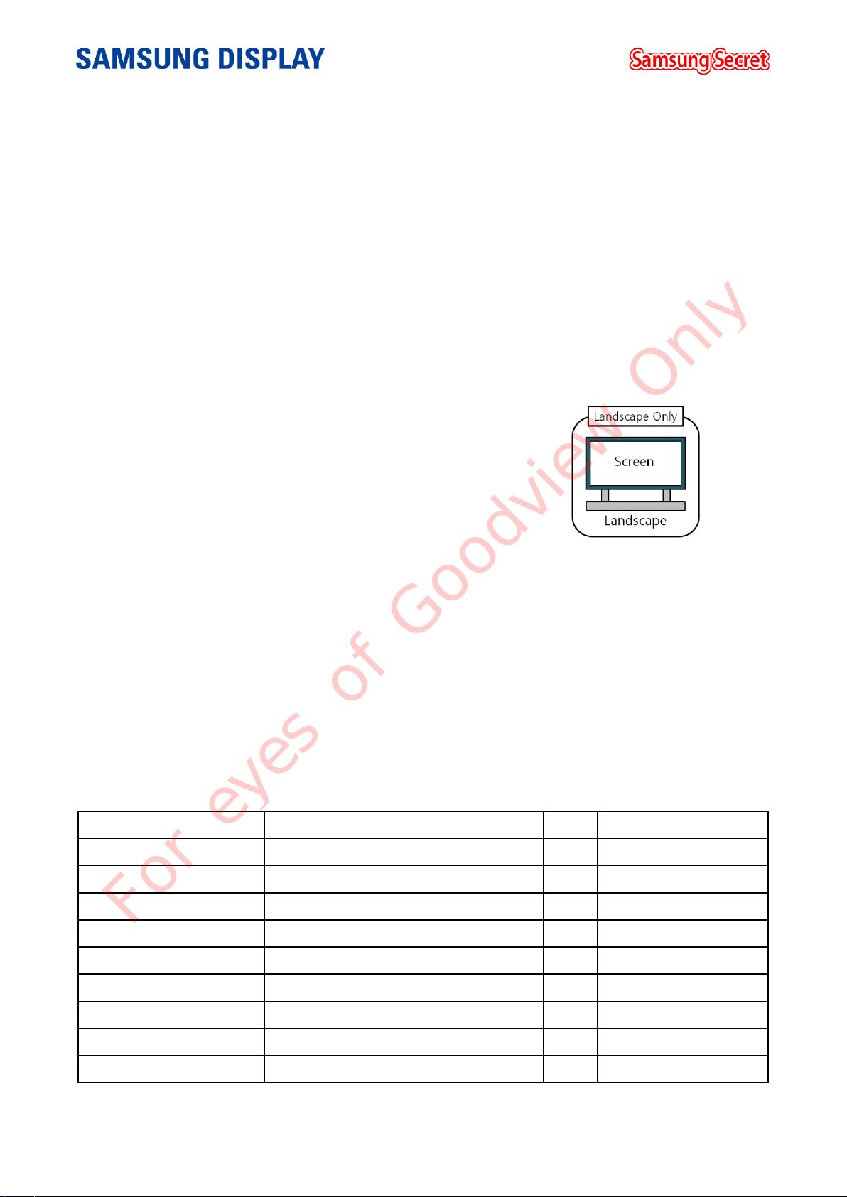
Display area
1805.76 (H) x 1015.74 (V)
mm Driver Element
a-Si TFT active matrix
Display colors
16.7M (8bit)
Number of pixel
1,920 x 1,080
Pixel
Pixel Arrangement
RGB Vertical stripe
Pixel pitch
940.5 (H) x 940.5 (V) (TYP.)
mm Display Mode
Normally Black
Surface treatment
Haze 2.3% / 2H
Anti-Glare
Luminance of White
450(Typ)
cd/m2
For eyes of Goodview Only
————————————————————————————————————————————————
GENERAL DESCRIPTION
DESCRIPTION
LTI820HA01-0 is a color active matrix liquid crystal display (LCD) that uses amorphous silicon TFT(Thin Film
Transistor) as switching components. This model is composed of a TFT LCD panel, a driver circuit, and a backlight unit. This 82.0” model has a resolution of 1,920 x 1,080 pixels (16:9) can display up to 16.7 Million colors
with the wide viewing angle of 89° or higher in all directions.
FEATURES
RoHS compliance (Pb-free)
FHD(1,920X1,080) resolution (16:9)
SPVA(Super Patterned Vertical Align) mode
High Tni (85℃) Liquid Crystal
High speed response
High contrast ratio, High aperture ratio with the wide color gamut
Wide viewing angle (± 178°)
Landscape type only compatible
LVDS(Low Voltage Differential Signaling) Interface(2pixel/clock)
DE(Data Enable) mode
Bar Type Edge LED(Light Emitting Diode)
Low power consumption
APPLICATIONS
Digital Information Display (DID)
High Definition Public Monitor
GENERAL INFORMATION
——————————————————————————————————————————————––—
Doc.No. LTI820HA01-0 Page 4 of 32 Rev.No. 06-001-G-130820
Page 5
Item
Min.
Typ.
Max.
Unit
Note
Module
Size
Horizontal (H)
1854.0
1856.0
1858.0
mm Vertical (V)
1080.0
1082.0
1084.0
mm Depth (D)
15.0
16.0
18.0
mm
Minimum Depth (2)
Bezel
Open
Horizontal (H)
-
1816.0
-
mm Vertical (V)
-
1026.0
-
mm
Black
Matrix
Shift
Horizontal (H)
- - 3.0
mm
(1)
Vertical (V)
- - 3.0
mm
Weight
-
43,000
45,000 g
For eyes of Goodview Only
————————————————————————————————————————————————
MECHANICAL INFORMATION
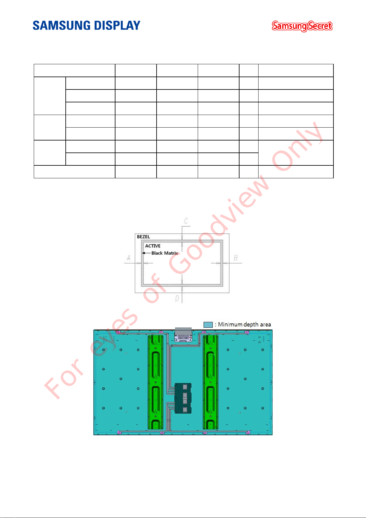
Note (1) Measure the figure for Black Matrix shift to be recorded on the spec. with referring to the drawings.
- | A - B | ≤ Horizontal Spec
- | C - D | ≤ Vertical Spec
Note (2) Measure point of Depth
——————————————————————————————————————————————––—
Doc.No. LTI820HA01-0 Page 5 of 32 Rev.No. 06-001-G-130820
Page 6
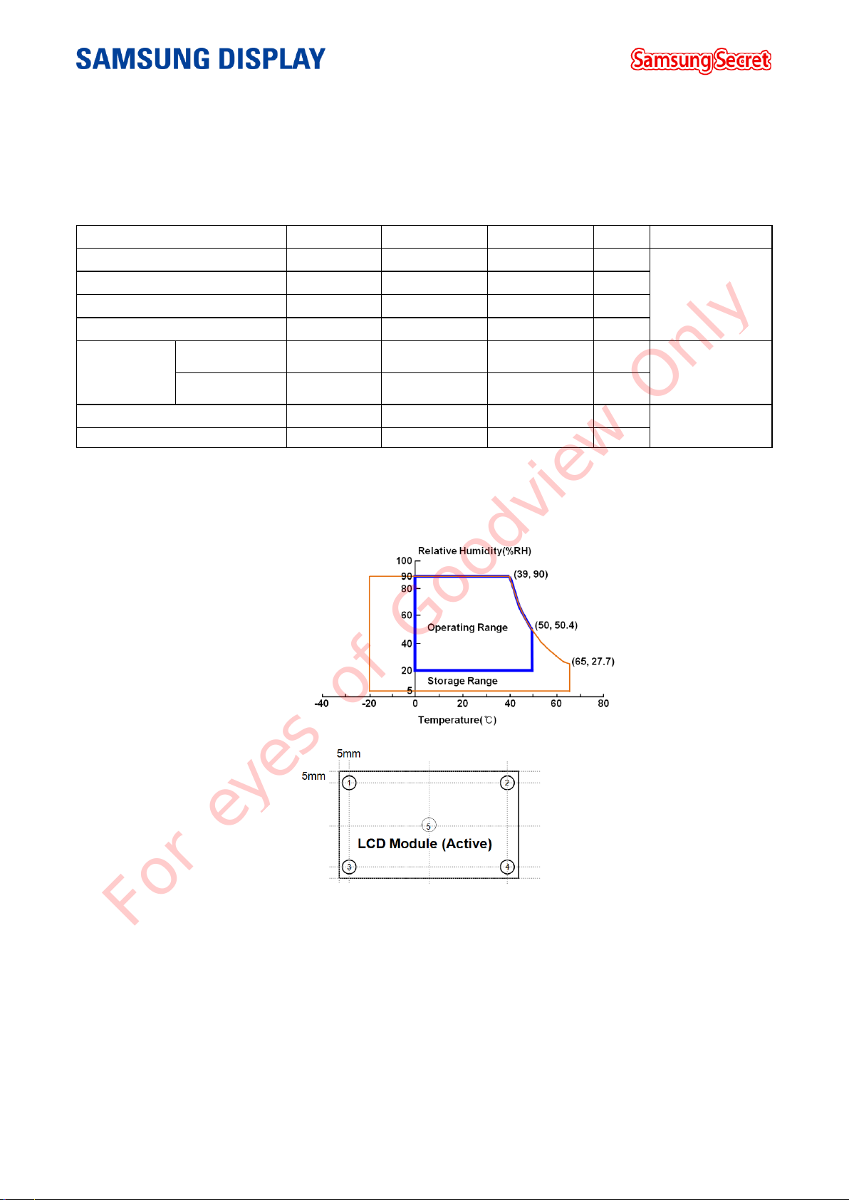
△T should be less than 10 ℃ (△T = |T
CENTER
– T
CORNER
| )
T
CENTER
: Temperature of the center of the glass surface (Test point 5)
T
CORNER
: Temperature of each edge of the glass surface (Test point 1~4)
Item
Symbol
Min.
Max.
Unit
Note
Storage temperature
T
STG
-20
65
C
(1)
Operation Temperature
T
OPR
0 50
C
Humidity for storage
HSTG 5 90
%RH
Operating humidity
HOPR
20
90
%RG
Glass Surface
temperature
(Operation)
Center
T
Center
0 50
C
(2)
T Uniformity
△T - 10
C
Shock ( non-operating )
Snop(X,Y,Z)
-
-
G
(3)
Vibration (non-operating)
V
nop
- -
G
For eyes of Goodview Only
————————————————————————————————————————————————
1. ABSOLUTE MAXIMUM RATINGS
1.1 ENVIRONMENTAL ABSOLUTE RATINGS
Note (1) Temperature and relative humidity range are shown in the figure below.
a. 90 % RH Max. (Ta ≤ 39 °C)
b. Relative Humidity is 90% or less. (Ta > 39 °C)
c. No condensation
Note (2) Definition of test point
Note (3) Module vibration and shock tests are not guaranteed due to limitation of equipment for this model.
——————————————————————————————————————————————––—
Doc.No. LTI820HA01-0 Page 6 of 32 Rev.No. 06-001-G-130820
Page 7
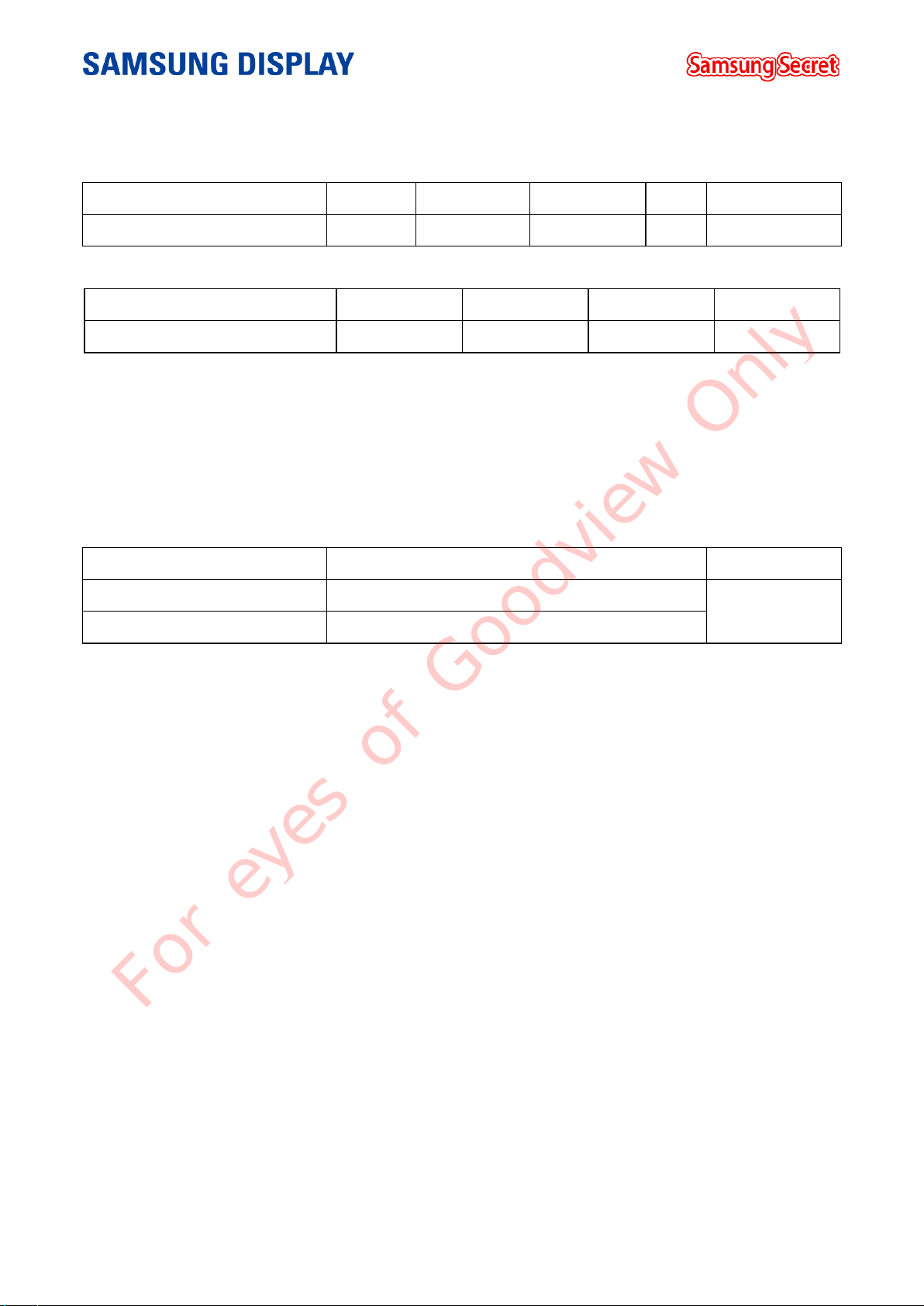
Item
Symbol
Min.
Max.
Unit
Note
Power Supply Voltage
VDD
10.8
13.2
V
(1)
Item
Symbol
Max.
Unit.
Note
Input Supply Voltage
VCC
26 V (1)
Item
Test Conditions
Remark
Contact Discharge
150pF, 330Ω, ±10kV, 210points, 1time/point
Operating
Air Discharge
150pF, 330Ω, ±20kV, 210points, 1time/point
For eyes of Goodview Only
————————————————————————————————————————————————
1.2 ELECTRICAL ABSOLUTE RATINGS
(1) TFT LCD MODULE
(2) BACKLIGHT UNIT
Note (1) Ta= 25 ± 2 °C
The permanent damage or defect to the device may occur if the panel is operated at the figure set, which
exceeds a ceiling of maximum value stated in the former spec. The functional operation should be limited to
the conditions described above under normal operating conditions.
1.3 THE OTHERS ABSOLUTE RATINGS
Static Electricity Pressure Resistance
——————————————————————————————————————————————––—
Doc.No. LTI820HA01-0 Page 7 of 32 Rev.No. 06-001-G-130820
Page 8

For eyes of Goodview Only
————————————————————————————————————————————————
2. APPLICATION INFORMATION FOR DID
(Digital Information Display)
A DID’s screen may display the sudden image such as an image retention.
To extend the lifetime and optimize a function of module, the below-mentioned operating
conditions are required.
2.1 Normal operating condition
a. Temperature: 20 ± 15℃
b. Humidity: 55 ± 20 %
c. Display pattern: Moving image or image, which switches regularly.
Note) The sudden image on the screen can be displayed after the static image is shown in the long-term.
2.2 The operating conditions when the module is operated under the abnormal
condition.
a. Ambient condition
-It is recommended to set the DID up in the well-ventilated place.
b. The function of power off and screen saver
-The function of periodical power-off or a screen saver is needed when the static image is displayed
in the long-term.
2.3 Operating conditions to prevent the sudden display resulted from displaying
the static image in the long-term.
a. The proper operating time: Under 12 hours a day.
b. The moving image shall be inserted between the static displays periodically.
-The refresh time for liquid crystal is needed.
c. The periodic changing of background color and character’s color(image)
-Use the different color for background and character (image) respectively.
-Change colors periodically.
d. Avoid combining the color for background with the color for character, which has a largely different
luminance.
Note(1) Abnormal condition means all operating condition except normal operating condition.
Note(2) The moving image or black pattern is strongly recommended as a screen saver.
2.4 Only the lifetime of DID stated in this spec is guaranteed if the DID is used under
the proper operating conditions.
2.5 Clean the system regularly for not accumulating the dust around the system
considering user environment, otherwise, its reliability and function may
not be satisfied.
——————————————————————————————————————————————––—
Doc.No. LTI820HA01-0 Page 8 of 32 Rev.No. 06-001-G-130820
Page 9
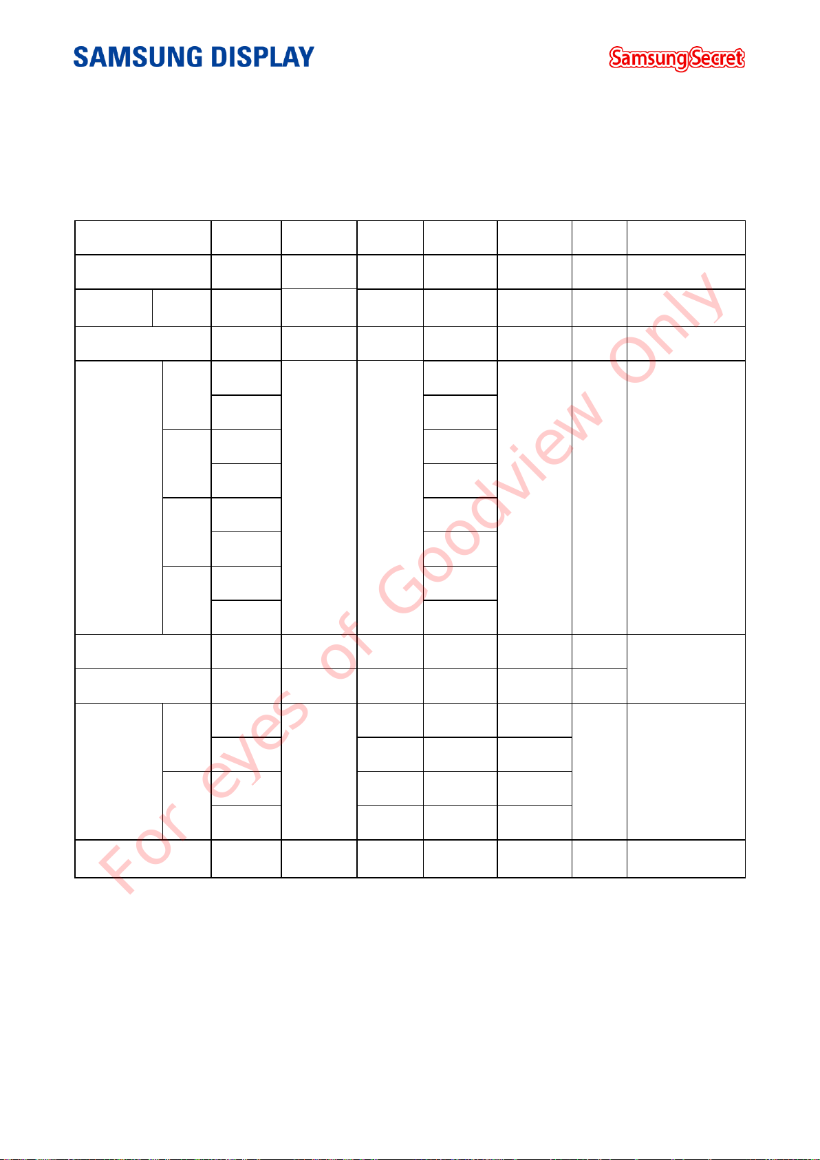
Item
Symbol
Condition
Min.
Typ.
Max.
Unit
Note
Contrast Ratio
C/R
-
3000
5000
- - (3) SR-3
Response
time
G-to-G
(AVG)
Tg
- - 8
16
msec
(5) RD-80S
Luminance of White
(At the center of screen)
YL
-
360
450
-
cd/m2
(6) SR-3
Color
Chromaticity
(CIE 1931)
Red
RX
Normal
= 0
= 0
Viewing
Angle
TYP.
-0.03
0.640
TYP
+0.03
-
(7), (8)
SR-3
RY
0.330
Green
GX
0.300
GY
0.605
Blue
BX
0.150
BY
0.060
White
WX
0.270
WY
0.285
Color Gamut
- - 67
70 - %
(7)
SR-3
Color temperature
- - -
11500
-
K
Viewing
Angle
Hor.
L
CR 10
75
89
-
Degree
(8)
SR-3
EZ-Contrast
R
75
89
-
Ver.
U
75
89
-
D
75
89
-
Brightness Uniformity
(9 Point)
B
uni
- - -
25.0
%
(4)
SR-3
For eyes of Goodview Only
————————————————————————————————————————————————
3. OPTICAL CHARACTERISTICS
The optical characteristics should be measured in a dark room or equivalent.
Measuring equipment : TOPCON RD-80S, SR-3, ELDIM EZ-Contrast
Ta = 25 2 C, VDD =3.3V, fv= 60Hz, f
= 148.5MHz, IF=100% duty
DCLK
Note(1) Test Equipment Setup
——————————————————————————————————————————————––—
Doc.No. LTI820HA01-0 Page 9 of 32 Rev.No. 06-001-G-130820
The measurement should be executed in a stable, windless and dark room between 40min and 60min
after lighting the backlight at the given temperature for stabilization of the backlight. This should be
measured in the center of screen.
LED : IF=150mA (Per String)
Environment condition : Ta = 25 ± 2 °C
Page 10
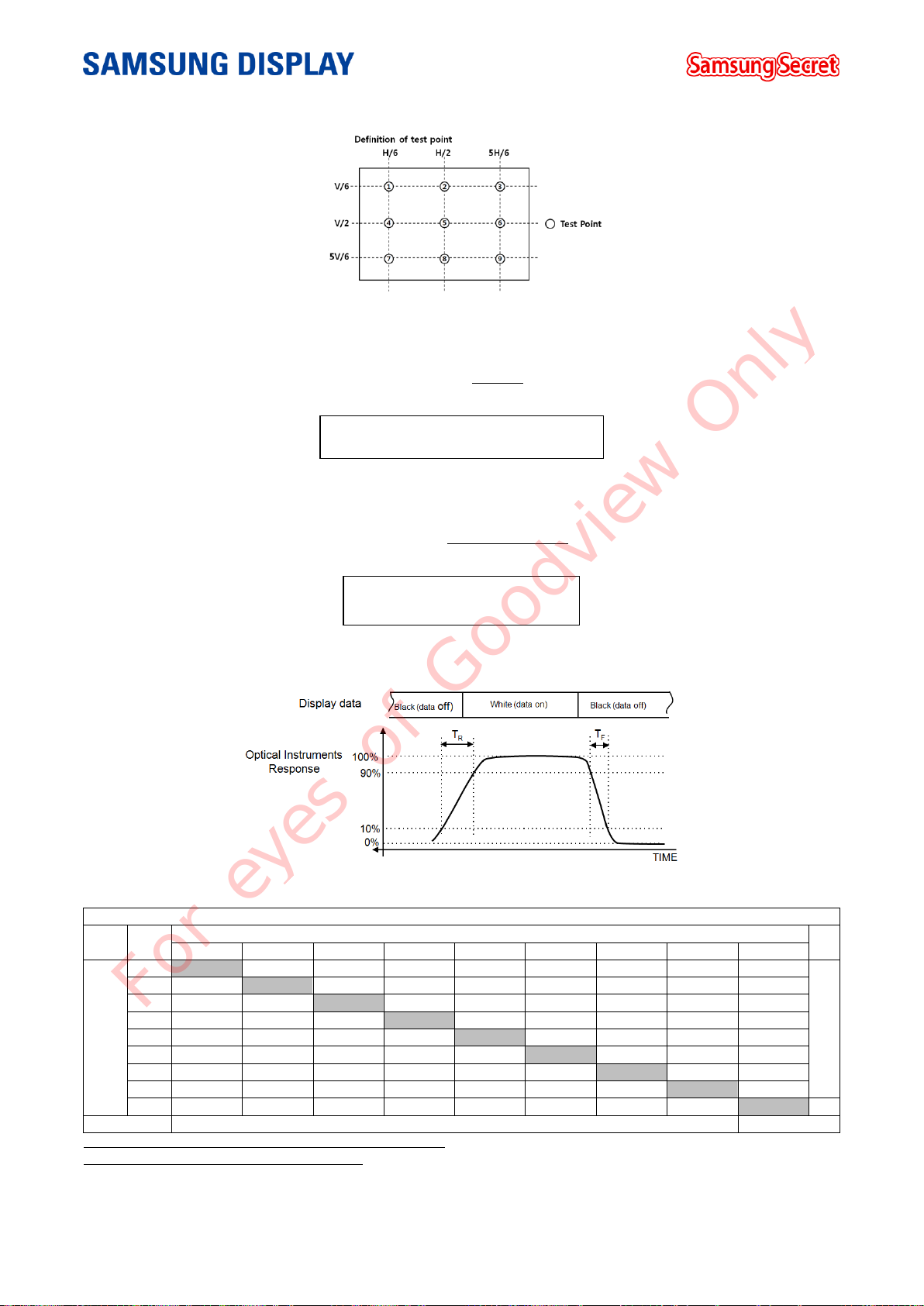
C R
G
G
/
max
min
Gmax : Luminance in all white pixels
Gmin : Luminance in all black pixels.
Buni
B B
B
100
( max min)
max
Bmax : Maximum brightness
Bmin : Minimum brightness
Gray to Gray Response Time
Gray
End
0
31
63
95
127
159
191
223
255
Start
0 Tr(0-31)
Tr(0-63)
Tr(0-95)
Tr(0-127)
Tr(0-159)
Tr(0-191)
Tr(0-223)
Tr(0-255)
TON
31
Tr(31-0)
Tr(31-63)
Tr(31-95)
Tr(31-127)
Tr(31-159)
Tr(31-191)
Tr(31-223)
Tr(31-255)
63
Tr(63-0)
Tr(63-31)
Tr(63-95)
Tr(63-127)
Tr(63-159)
Tr(63-191)
Tr(63-223)
Tr(63-255)
95
Tr(95-0)
Tr(95-31)
Tr(95-63)
Tr(95-127)
Tr(95-159)
Tr(95-191)
Tr(95-223)
Tr(95-255)
127
Tr(127-0)
Tr(127-31)
Tr(127-63)
Tr(127-95)
Tr(127-159)
Tr(127-191)
Tr(127-223)
Tr(127-255)
159
Tr(159-0)
Tr(159-31)
Tr(159-63)
Tr(159-95)
Tr(159-127)
Tr(159-191)
Tr(159-223)
Tr(159-255)
191
Tr(191-0)
Tr(191-31)
Tr(191-63)
Tr(191-95)
Tr(191-127)
Tr(191-159)
Tr(191-223)
Tr(191-255)
223
Tr(223-0)
Tr(223-31)
Tr(223-63)
Tr(223-95)
Tr(223-127)
Tr(223-159)
Tr(223-191)
Tr(223-255)
255
Tr(255-0)
Tr(255-31)
Tr(255-63)
Tr(255-95)
Tr(255-127)
Tr(255-159)
Tr(255-191)
Tr(255-223)
T
OFF
For eyes of Goodview Only
————————————————————————————————————————————————
Note(2) Definition of test point
Note(3) Definition of Contrast ratio(C/R)
: Ratio of max.gray(Gmax) & min.gray(Gmin) at the center point ⑤ of the panel.
Note(4) Definition of brightness uniformity at 9 points(Test pattern : Full white)
Note(5) Definition of Response time : Average response time of all Gray to Gray except Tr, Tf
※ G-to-G : Average response time between the whole gray scale to the whole gray scale.
T*(X-Y) : Response time from level of gray at X to level of gray at Y
The definition of response time = Σ [T*(X-Y)] / 72
——————————————————————————————————————————————––—
Doc.No. LTI820HA01-0 Page 10 of 32 Rev.No. 06-001-G-130820
Page 11

For eyes of Goodview Only
————————————————————————————————————————————————
Note(6) Definition of Luminance of White : Luminance of white at center point ⑤
Note(7) Definition of Color Chromaticity (CIE 1931)
Color coordinate of Red, Green, Blue & White at center point ⑤
Note(8) Definition of Viewing Angle : Viewing angle range(C/R ≥ 10)
——————————————————————————————————————————————––—
Doc.No. LTI820HA01-0 Page 11 of 32 Rev.No. 06-001-G-130820
Page 12
Item
Symbol
Min.
Typ.
Max.
Unit
Note
Voltage of Power Supply
VDD
10.8
12.0
13.2 V (1)
Current of
Power
Supply
(a) Black
IDD
-
700
870
mA
(2), (3)
(b) White
-
600
730
(C) N-Pattern
-
1650
2180
Vsync Frequency
fV
48
60
62
Hz
-
Hsync Frequency
fH
54
67.5
69.75
kHz
-
Main Frequency
F
dclk
118.8
148.50
153.5
MHz - Rush Current
I
RUSH
- - 4 A (4)
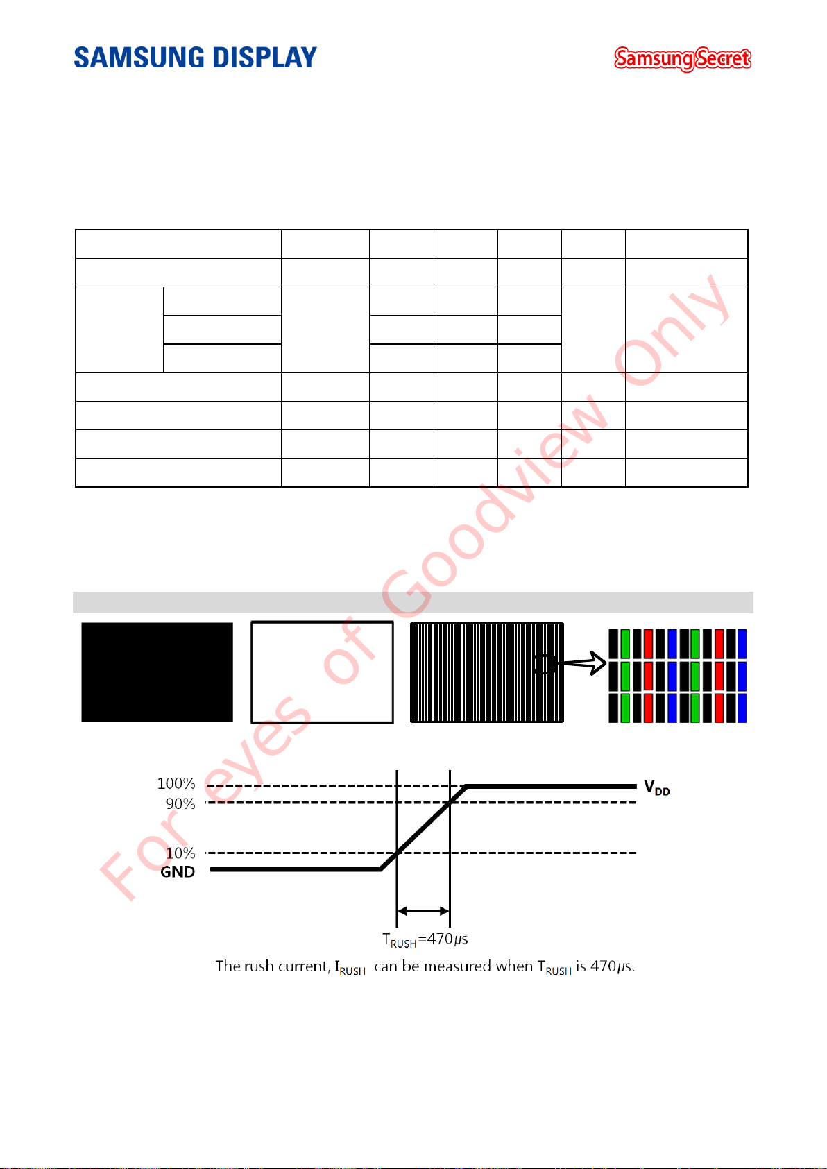
a) Black Pattern
b) White Pattern
c) Sub-V-Stripe-pattern
For eyes of Goodview Only
————————————————————————————————————————————————
4. ELECTRICAL CHARACTERISTICS
4.1 TFT LCD MODULE
The connector to transmit a display data and a timing signal should be connected.
Ta = 25 ± 2 °C
Note(1) The ripple voltage should be controlled under 10% of VDD.
Note(2) fV=60Hz, f
Note(3) The pattern for checking the power dissipation (LCD module only).
Note(4) Conditions for measurement
=148.5MHz, VDD=12.0V, DC Current.
DCLK
——————————————————————————————————————————————––—
Doc.No. LTI820HA01-0 Page 12 of 32 Rev.No. 06-001-G-130820
Page 13
Item
Symbol
Min.
Typ.
Max.
Unit
Note
Operating Life Time
Hr
-
50,000
-
Hour
(1)
For eyes of Goodview Only
————————————————————————————————————————————————
4.2 BACKLIGHT UNIT
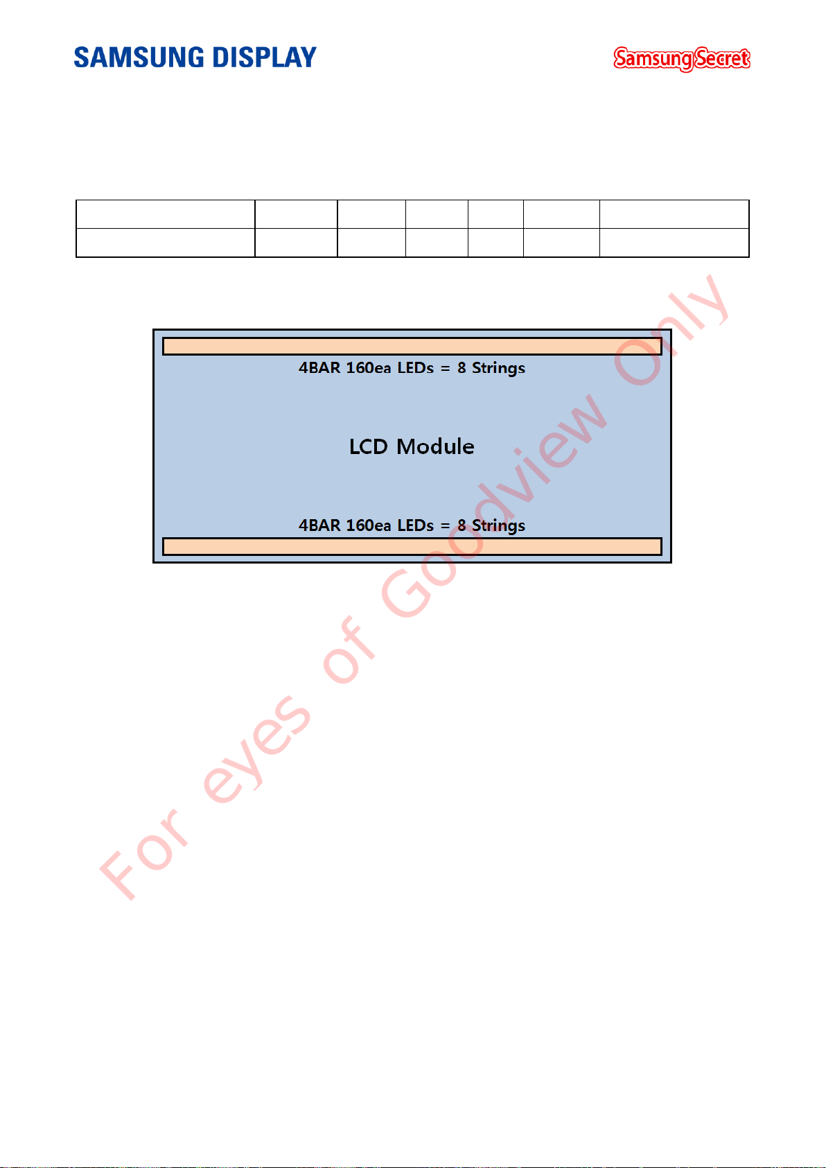
The back light unit contains 8 Bar type 320 LEDs (Light Emitting Diode).
The characteristics of BLU are shown in the following tables.
Ta = 25 2 C
Note(1) It is defined as the time to take until the brightness reduces to 50% of its original value.
[Operating condition : Ta = 25± 2℃, IF = 150mA, For single LED string only]
——————————————————————————————————————————————––—
Doc.No. LTI820HA01-0 Page 13 of 32 Rev.No. 06-001-G-130820
Page 14
Items
Symbol
Conditions
Specifications
Unit
Note
Min
Typ
Max
Input
Voltage
Vin - 22
24
26
V
Ta=25±2℃
Input
Current
Iin
Vin = 24V
Dim = Max
- - 19.74 A -
Output
Current
I
LED
Vin = 24V
Dim = Max
143
150
157
mA
(rms)
Per String
Backlight
On/Off
Control
ENA
Enable
2.4 - 5.25
V
-
Disable
0 - 0.4
Analog
Dimming
V
A_Dim
Vin = 24V
0 - 3.3
V
Converter input
Pin#14 : N.C.
Dimming
20 - 100
%
Items
Symbol
Conditions
Specification
Unit
Min
Typ
Max
Input
Current
I
in_Overshoot
Vin=24V, Dim=3.3V
(Within 1hr at BLU On)
-
13.76
14.15
A
I
in_Saturation
Vin=24V, Dim=3.3V
(After 1hr Aging)
-
13.52
13.91
For eyes of Goodview Only
————————————————————————————————————————————————
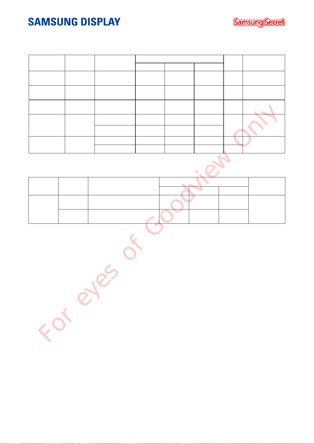
4.3 LED CONVERTER CHARACTERISTICS
Note (1) All data was approved after running 120 minutes.
※ Additional appendix for supply current
——————————————————————————————————————————————––—
Doc.No. LTI820HA01-0 Page 14 of 32 Rev.No. 06-001-G-130820
Page 15
PIN No.
Description
PIN No.
Description
1
VDD (12V)
26
Even
LVDS
Signal
Rx2[A]P
2
VDD (12V)
27
Rx2[B]N
3
VDD (12V)
28
Rx2[B]P 4 VDD (12V)
29
Rx2[C]N 5 VDD (12V)
30
Rx2[C]P 6 No Connection
31
GND 7 GND
32
Rx2CLK_N 8 GND
33
Rx2CLK_P 9 GND
34
GND
10
Odd
LVDS
Signal
Rx1[A]N
35
Rx2[D]N
11
Rx1[A]P
36
Rx2[D]P
12
Rx1[B]N
37
No Connection
13
Rx1[B]P
38
No Connection
14
Rx1[C]N
39
GND
15
Rx1[C]P
40
No Connection
16
GND
41
No Connection
17
Rx1CLK_N
42
No Connection
18
Rx1CLK_P
43
No Connection
19
GND
44
No Connection
20
Rx1[D]N
45
LVDS_SEL
21
Rx1[D]P
46
No Connection
22
No Connection
47
No Connection
23
No Connection
48
No Connection
24
GND
49
No Connection
25
Even LVDS
Rx2[A]N
50
No Connection
51
No Connection
For eyes of Goodview Only
————————————————————————————————————————————————
5. INPUT TERMINAL PIN ASSIGNMENT
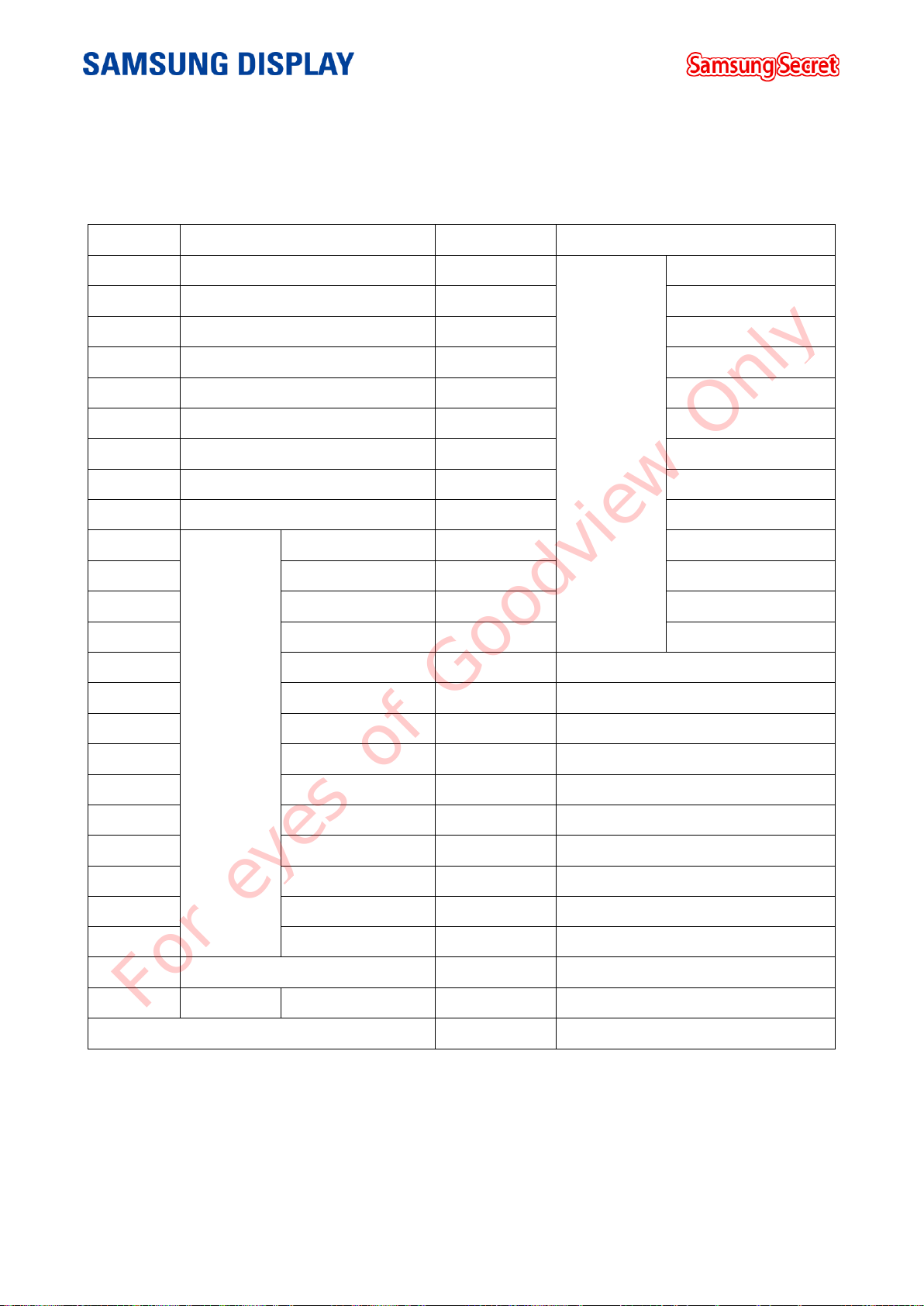
5.1 INPUT SIGNAL & POWER
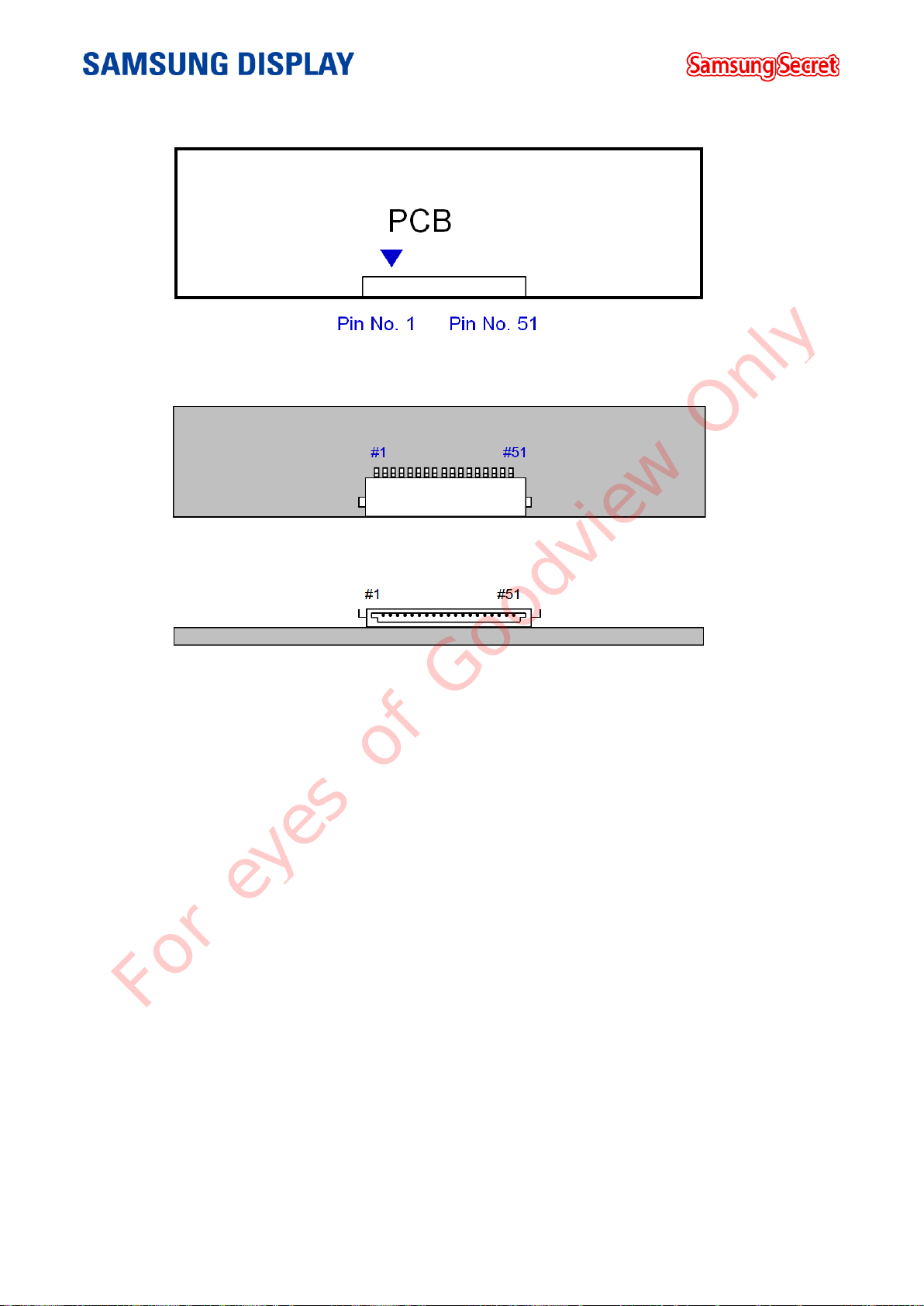
Connector : FI-RE51S-HF-J (JAE)
Note (1) No Connection : These pins are only used for SAMSUNG internal purpose.
Note (2) LVDS Option : High(3.3V) Normal NS LVDS format
Low(GND or N.C) JEIDA LVDS format
Sequence : On = VDD(T1) ≥ LVDS Option ≥ Interface Signal(T2)
Off = Interface Signal(T3) ≥ LVDS Option ≥ VDD
——————————————————————————————————————————————––—
Doc.No. LTI820HA01-0 Page 15 of 32 Rev.No. 06-001-G-130820
Page 16
For eyes of Goodview Only
————————————————————————————————————————————————
Note (3) LVDS Connector
a. All GND pins should be connected together and also be connected to the LCD’s metal chassis.
b. All power input pins should be connected together.
c. All N.C pins should be separated from other signal or power.
——————————————————————————————————————————————––—
Doc.No. LTI820HA01-0 Page 16 of 32 Rev.No. 06-001-G-130820
Page 17
PIN NO
Pin Configuration(FUNCTION)
1, 2, 3, 4, 5
Vin(24V)
6, 7, 8, 9, 10
GND
11
No Connection
12
ENA (Converter On/Off Control Signal)
DC 0 to 0.4V : Off / 2.4~5.25V : On
13
Analog Dimming Control [0V : Min / 3.3V : Max]
14
No Connection
PIN NO
Pin Configuration(FUNCTION)
1, 2, 3, 4, 5
Vin(24V)
6, 7, 8, 9, 10
GND
11
No Connection
12
No Connection
13
No Connection
14
No Connection
For eyes of Goodview Only
————————————————————————————————————————————————
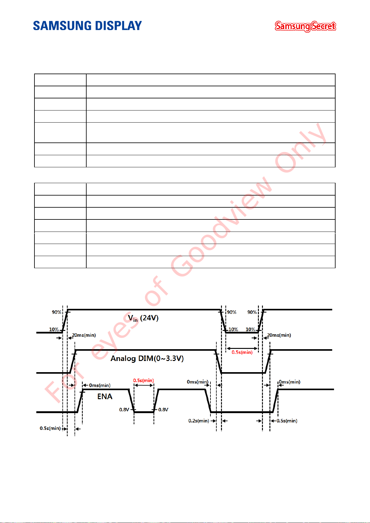
5.2 LED CONVERTER INPUT PIN CONFIGURATION
CN1(Master) : Connector : YEONHO, 22022WR-014B1
CN2 : Connector : YEONHO, 22022WR-014B1
5.3 LED CONVERTER POWER SEQUENCE
——————————————————————————————————————————————––—
Doc.No. LTI820HA01-0 Page 17 of 32 Rev.No. 06-001-G-130820
Page 18
LVDS pin
JEIDA -DATA
VESA -DATA
TxOUT/RxIN0
TxIN/RxOUT0
R2
R0
TxIN/RxOUT1
R3
R1
TxIN/RxOUT2
R4
R2
TxIN/RxOUT3
R5
R3
TxIN/RxOUT4
R6
R4
TxIN/RxOUT6
R7
R5
TxIN/RxOUT7
G2
G0
TxOUT/RxIN1
TxIN/RxOUT8
G3
G1
TxIN/RxOUT9
G4
G2
TxIN/RxOUT12
G5
G3
TxIN/RxOUT13
G6
G4
TxIN/RxOUT14
G7
G5
TxIN/RxOUT15
B2
B0
TxIN/RxOUT18
B3
B1
TxOUT/RxIN2
TxIN/RxOUT19
B4
B2
TxIN/RxOUT20
B5
B3
TxIN/RxOUT21
B6
B4
TxIN/RxOUT22
B7
B5
TxIN/RxOUT24
HSYNC
HSYNC
TxIN/RxOUT25
VSYNC
VSYNC
TxIN/RxOUT26
DEN
DEN
TxOUT/RxIN3
TxIN/RxOUT27
R0
R6
TxIN/RxOUT5
R1
R7
TxIN/RxOUT10
G0
G6
TxIN/RxOUT11
G1
G7
TxIN/RxOUT16
B0
B6
TxIN/RxOUT17
B1
B7
TxIN/RxOUT23
RESERVED
RESERVED
For eyes of Goodview Only
————————————————————————————————————————————————
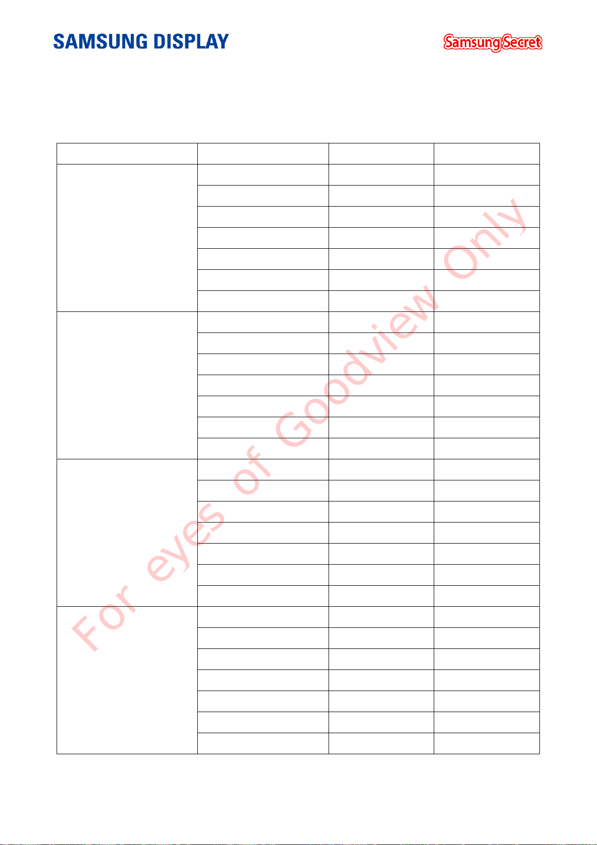
5.4 LVDS INTERFACE
- LVDS Receiver : Tcon(Merged)
- Data Format (JEIDA & Normal) Default LVDS Option : JEIDA
LVDS Option : High(3.3V) Normal NS LVDS format / Low(GND or N.C) JEIDA LVDS format
——————————————————————————————————————————————––—
Doc.No. LTI820HA01-0 Page 18 of 32 Rev.No. 06-001-G-130820
Page 19
COLOR
DISPLAY
(8bit)
DATA SIGNAL
GRAY
SCALE
LEVEL
RED
GREEN
BLUE
R0
R1
R2
R3
R4
R5
R6
R7
G0
G1
G2
G3
G4
G5
G6
G7
B0
B1
B2
B3
B4
B5
B6
B7
BASIC
COLOR
BLACK
0 0 0 0 0 0 0 0 0 0 0 0 0 0 0 0 0 0 0 0 0 0 0 0 -
BLUE
0 0 0 0 0 0 0 0 0 0 0 0 0 0 0 0 1 1 1 1 1 1 1 1 -
GREEN
0 0 0 0 0 0 0 0 1 1 1 1 1 1 1 1 0 0 0 0 0 0 0 0 -
CYAN
0 0 0 0 0 0 0 0 1 1 1 1 1 1 1 1 1 1 1 1 1 1 1 1 -
RED
1 1 1 1 1 1 1 1 0 0 0 0 0 0 0 0 0 0 0 0 0 0 0 0 -
MAGENTA
1 1 1 1 1 1 1 1 0 0 0 0 0 0 0 0 1 1 1 1 1 1 1 1 -
YELLOW
1 1 1 1 1 1 1 1 1 1 1 1 1 1 1 1 0 0 0 0 0 0 0 0 -
WHITE
1 1 1 1 1 1 1 1 1 1 1 1 1 1 1 1 1 1 1 1 1 1 1 1 -
GRAY
SCALE
OF
RED
BLACK
0 0 0 0 0 0 0 0 0 0 0 0 0 0 0 0 0 0 0 0 0 0 0 0 R0
DARK
↑
↓
LIGHT
1 0 0 0 0 0 0 0 0 0 0 0 0 0 0 0 0 0 0 0 0 0 0 0 R1
0 1 0 0 0 0 0 0 0 0 0 0 0 0 0 0 0 0 0 0 0 0 0 0 R2 : : : : : : : : : : : : : : : : : :
R3~
R252
: : : : : : : : : : : : : : : : : : 1 0 1 1 1 1 1 1 0 0 0 0 0 0 0 0 0 0 0 0 0 0 0 0 R253
0 1 1 1 1 1 1 1 0 0 0 0 0 0 0 0 0 0 0 0 0 0 0 0 R254
RED
1 1 1 1 1 1 1 1 0 0 0 0 0 0 0 0 0 0 0 0 0 0 0 0 R255
GRAY
SCALE OF
GREEN
BLACK
0 0 0 0 0 0 0 0 0 0 0 0 0 0 0 0 0 0 0 0 0 0 0 0 G0
DARK
↑
↓
LIGHT
0 0 0 0 0 0 0 0 1 0 0 0 0 0 0 0 0 0 0 0 0 0 0 0 G1 0 0 0 0 0 0 0 0 0 1 0 0 0 0 0 0 0 0 0 0 0 0 0 0
G2
: : : : : : : : : : : : : : : : :
:
G3~
G252
: : : : : : : : : : : : : : : : :
:
0 0 0 0 0 0 0 0 1 0 1 1 1 1 1 1 0 0 0 0 0 0 0 0 G253
0 0 0 0 0 0 0 0 0 1 1 1 1 1 1 1 0 0 0 0 0 0 0 0 G254
GREEN
0 0 0 0 0 0 0 0 1 1 1 1 1 1 1 1 0 0 0 0 0 0 0 0 G255
GRAY
SCALE OF
BLUE
BLACK
0 0 0 0 0 0 0 0 0 0 0 0 0 0 0 0 0 0 0 0 0 0 0 0 B0
DARK
↑
↓
LIGHT
0 0 0 0 0 0 0 0 0 0 0 0 0 0 0 0 1 0 0 0 0 0 0 0 B1
0 0 0 0 0 0 0 0 0 0 0 0 0 0 0 0 0 1 0 0 0 0 0 0 B2
: : : : : : : : : : : : : : : : :
:
B3~
B252
: : : : : : : : : : : : : : : : : : 0 0 0 0 0 0 0 0 0 0 0 0 0 0 0 0 1 0 1 1 1 1 1 1 B253 0 0 0 0 0 0 0 0 0 0 0 0 0 0 0 0 0 1 1 1 1 1 1 1
B254
BLUE
0 0 0 0 0 0 0 0 0 0 0 0 0 0 0 0 1 1 1 1 1 1 1 1 B255
For eyes of Goodview Only
————————————————————————————————————————————————
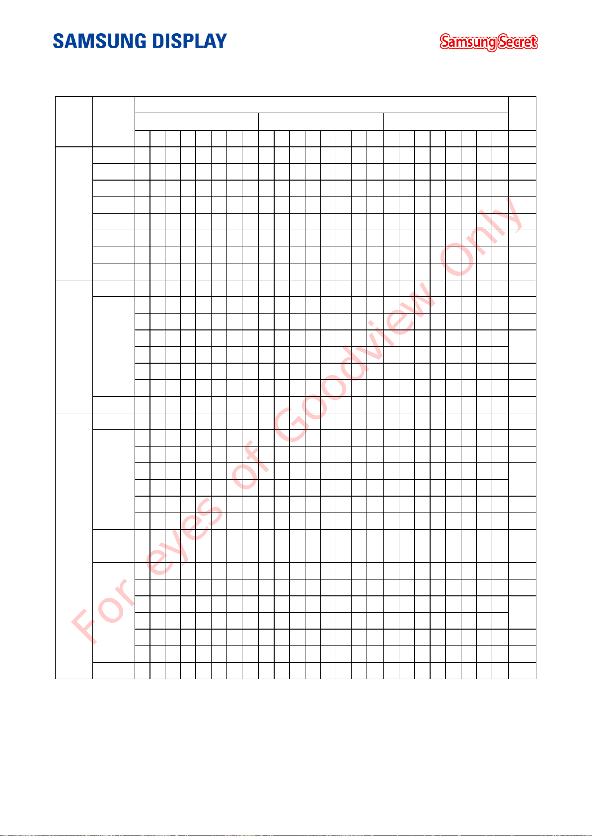
5.5 INPUT SIGNALS, BASIC DISPLAY COLORS AND GRAY SCALE
Note) Definition of Gray
Rn : Red Gray, Gn : Green Gray, Bn : Blue Gray(n = Gray Level)
Input Signal : 0 = Low Level Voltage, 1 = High Level Voltage
——————————————————————————————————————————————––—
Doc.No. LTI820HA01-0 Page 19 of 32 Rev.No. 06-001-G-130820
Page 20
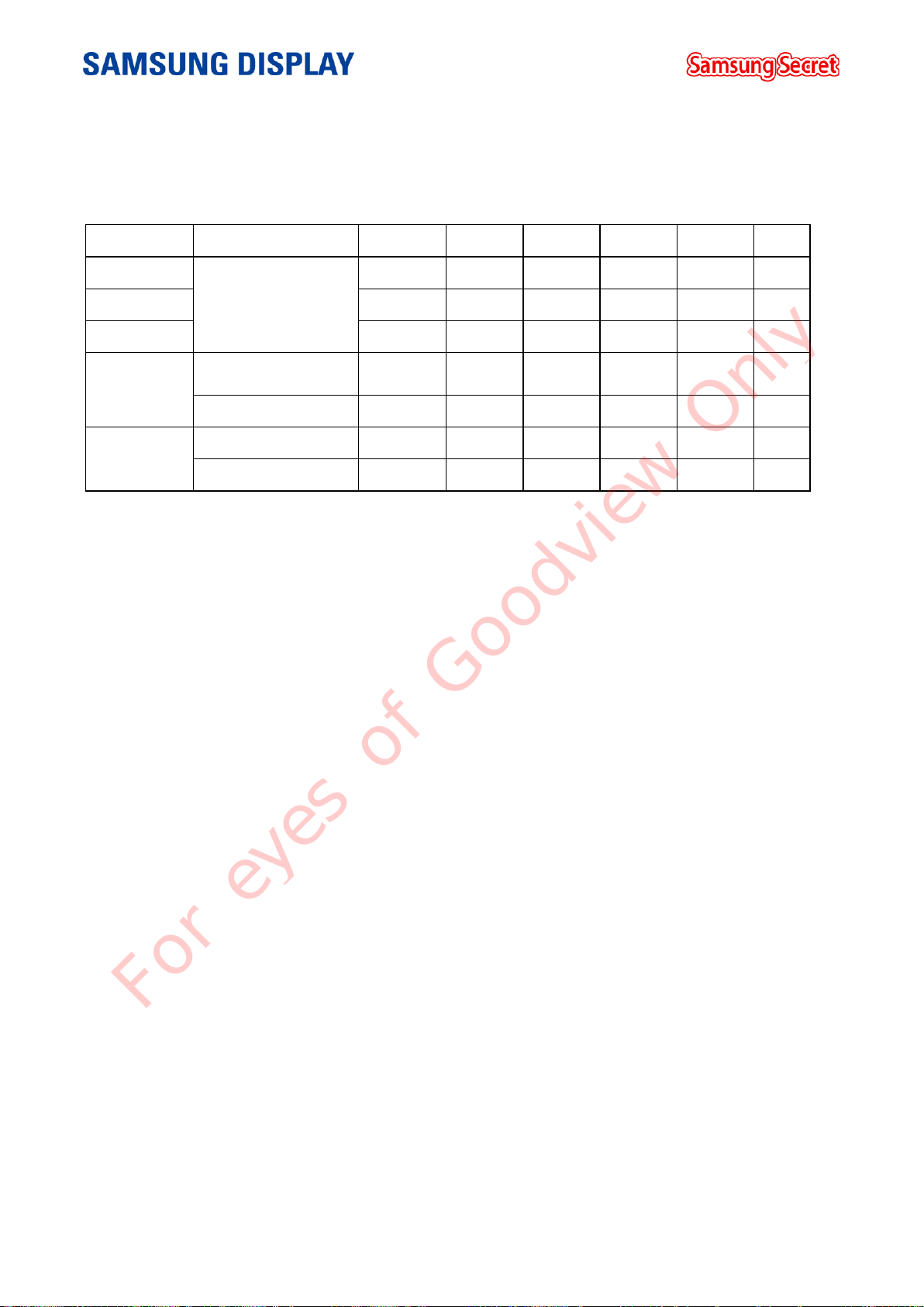
SIGNAL
ITEM
SYMBOL
MIN.
TYP.
MAX.
Unit
NOTE
Clock
Frequency
1/TC
118.8
148.5
153.5
MHz
-
Hsync
FH
54
67.5
69.75
KHz - Vsync
FV
48
60
62
Hz
-
Term for the
vertical
display
Active
display period
TVD
-
1080
-
Lines
-
Total vertical
TV
1090
1125
1158
Lines
-
Term for the
horizontal
display
Active display period
THD
-
1920
-
Clocks
-
Total Horizontal
TH
2080
2200
2350
clocks
-
For eyes of Goodview Only
————————————————————————————————————————————————
6. INTERFACE TIMING
6.1 TIMING PARAMETERS (DE ONLY MODE)
Note) The signals of Hsync and Vsync must be inputted even though this T-con is operated at DE mode.
(1) Test Point: TTL controls signal and CLK at LVDS Tx at the input terminal of system.
(2) Internal VDD = 3.3V
(3) The spread spectrum
- The limit of spread spectrum's range of SET in which the LCD module is assembled
should be within ± 3 %
- Frequency for modulation : Min 30KHz ~ Max 300KHz
——————————————————————————————————————————————––—
Doc.No. LTI820HA01-0 Page 20 of 32 Rev.No. 06-001-G-130820
Page 21
For eyes of Goodview Only
————————————————————————————————————————————————
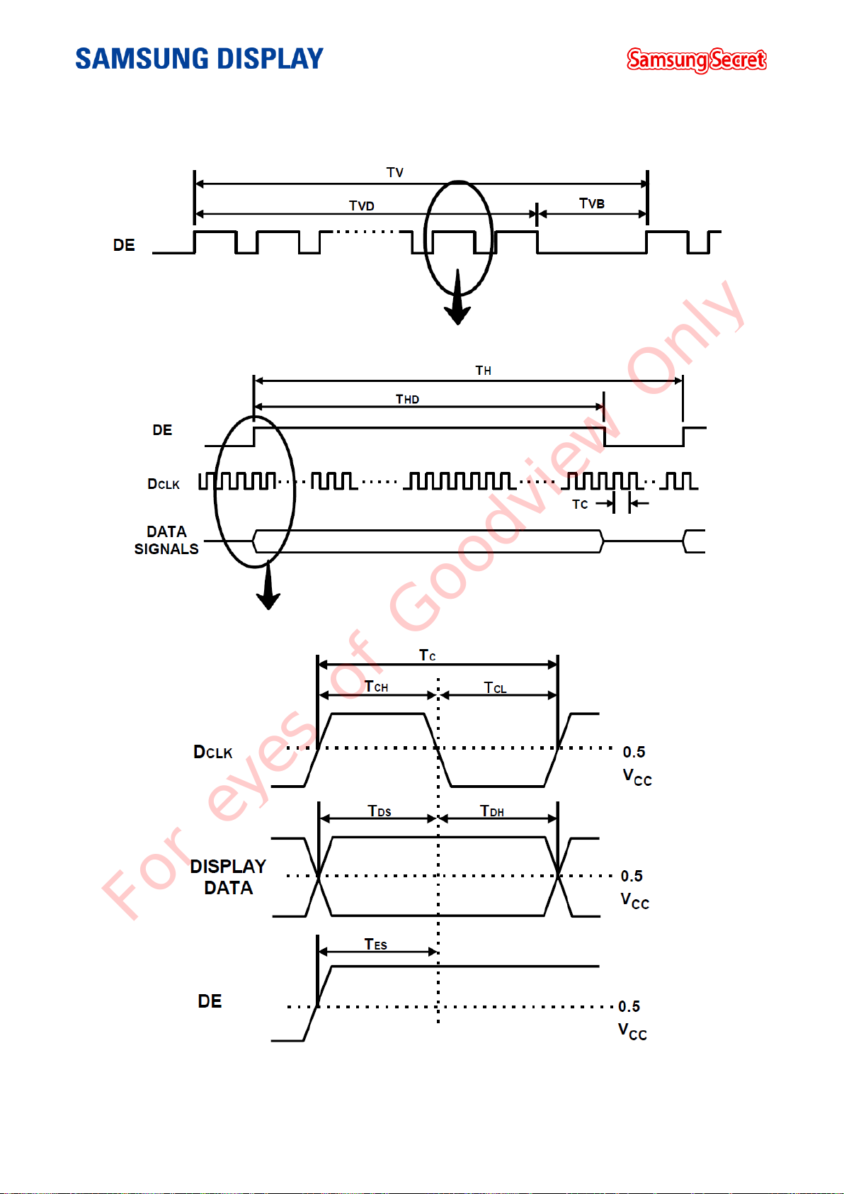
6.2 TIMING DIAGRAMS OF INTERFACE SIGNAL (DE ONLY MODE)
——————————————————————————————————————————————––—
Doc.No. LTI820HA01-0 Page 21 of 32 Rev.No. 06-001-G-130820
Page 22
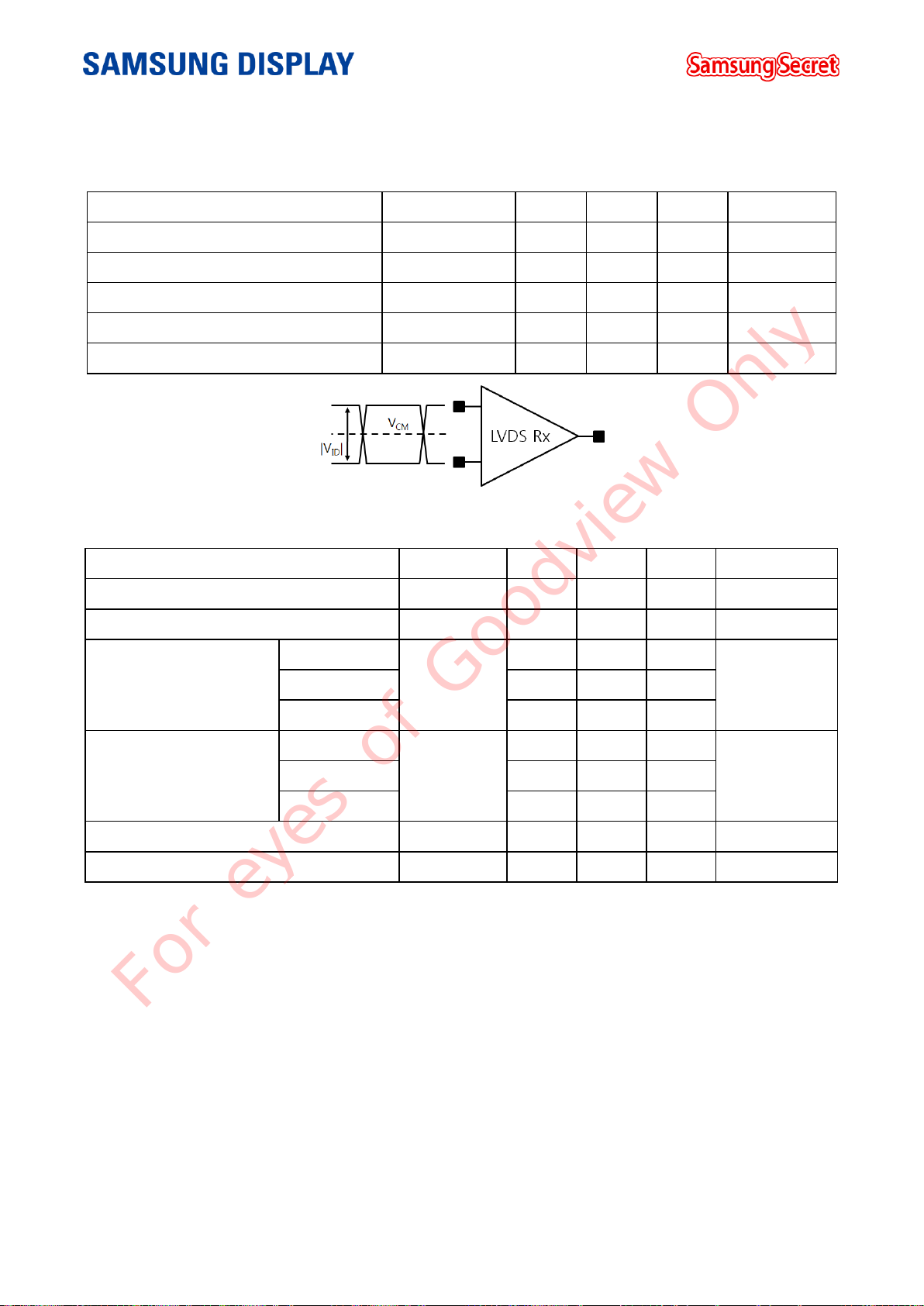
ITEM
SYMBOL
Min.
Typ.
Max.
UNIT
Supply voltage for IO
VDD33_LVDS
3.0
3.3
3.6 V Supply voltage in the core
VDD12_LVDS
1.1
1.2
1.3
V
Color depth
8
Bit
Input voltage at the common mode
VCM
0.3
1.8
V
Input voltage for differential
|VID|
100
350
600
mV
ITEM
SYMBOL
Min.
Typ.
Max.
UNIT
Frequency for input clock (=1/T)
FIN
25 - 90
MHz
Period of output clock
t
RCP
11.11 - 40
ns
Position of input data
FIN=85MHZ
t
RSRM
- - +400
ps
FIN=78MHZ
- - +450
FIN=75MHZ
- - +500
Position of input data
FIN=85MHZ
t
RSLM
-400 - -
ps
FIN=78MHZ
-450 - -
FIN=75MHZ
-500 - -
Lock time
t
RPLL
- - 100
usec
Duty ratio of Rx’s clock for output
T
duty
45
50
55
%
For eyes of Goodview Only
————————————————————————————————————————————————
6.3 CHARACTERISTICS OF INPUT DATA OF LVDS
(1) Specification for DC
(2) Specification for AC
——————————————————————————————————————————————––—
Doc.No. LTI820HA01-0 Page 22 of 32 Rev.No. 06-001-G-130820
Page 23
For eyes of Goodview Only
————————————————————————————————————————————————
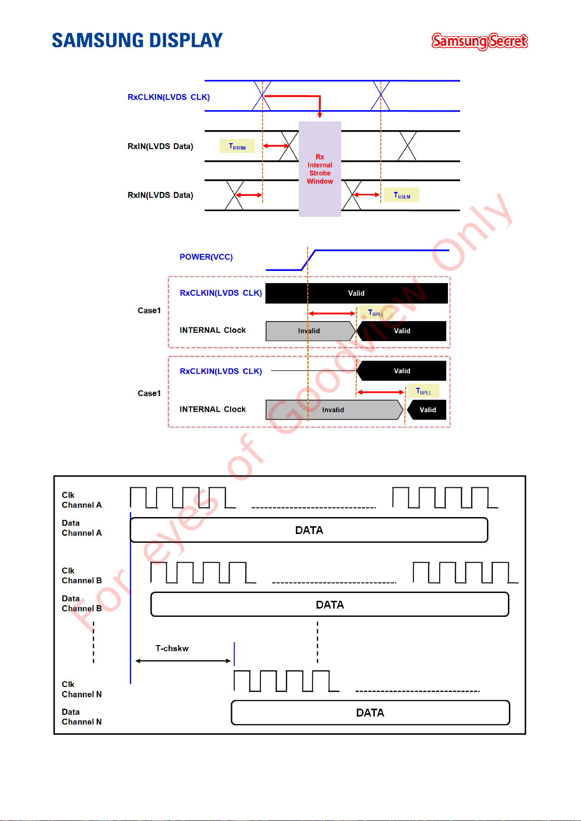
* LVDS Channel to Channel Skew(T-chskw) in Multiple LVDS Channels
Note : DE should be synchronized with DE per each LVDS Channel and T-chskw < 16* LVDS Clock Period
——————————————————————————————————————————————––—
Doc.No. LTI820HA01-0 Page 23 of 32 Rev.No. 06-001-G-130820
Page 24
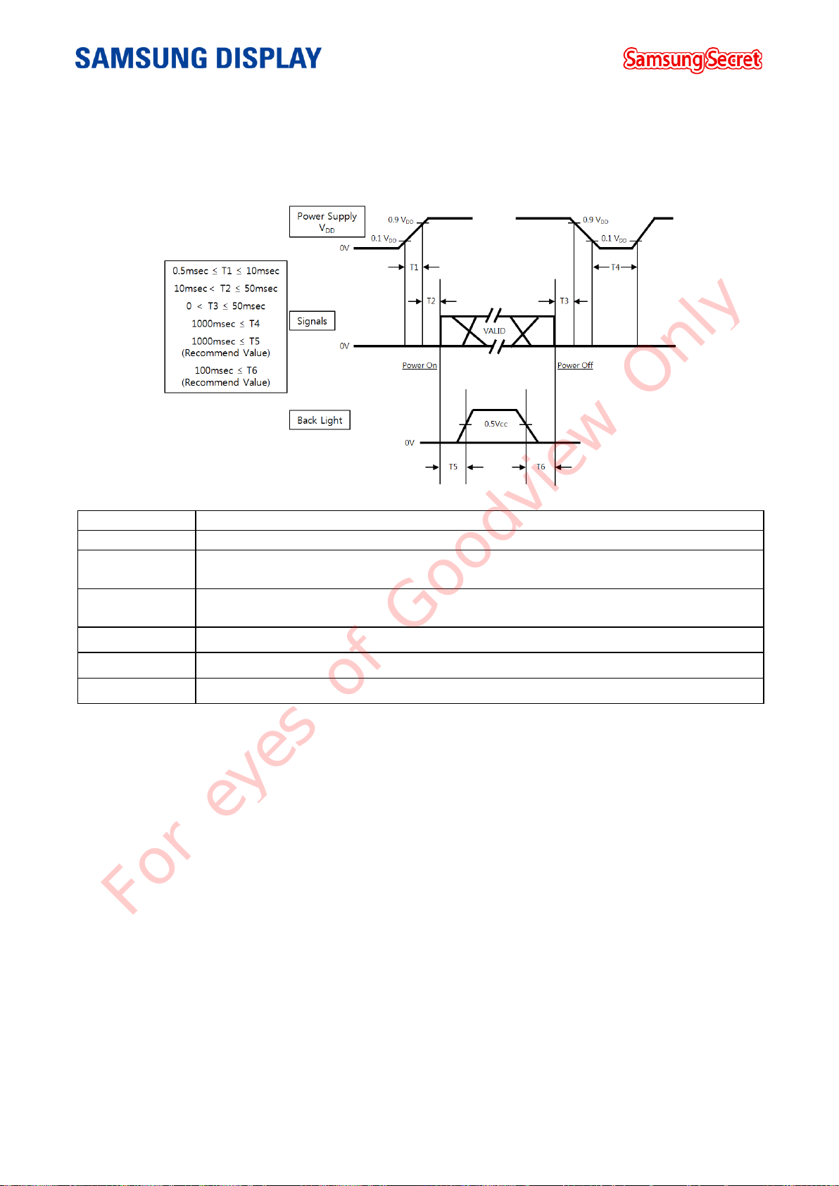
Timing
Remarks
T1
The time, during which the level of VDD is rising from 10% to 90%.
T2
The changing time, during which the V
DD
starts rising beyond 90% until the valid data of
signal started coming in.
T3
The changing time, during which the valid data of signal starts leaving out until the VDD
starts falling below 90%.
T4
The changing time, during which the VDD starts falling below 10% to restart the Windows.
T5
The changing time, during which the signal of BLU starts rising beyond 50%.
T6
The changing time, during which the signal of BLU starts falling below 50%.
For eyes of Goodview Only
————————————————————————————————————————————————
6.4 THE SEQUENCE OF POWER ON AND OFF
To prevent the product from being latched up or the DC in the LCD module from starting an operation, the
order to turn the power on and off should be changed to the order as shown in the diagram below.
- The inputted V
computed with referring to the former mentioned value.
- The method to apply the voltage to the LED within the range, which the LCD operates. When the back-light
is turned on before the LCD is operated or the power of LCD is turned off before the back-light is turned off,
the abnormal display on the screen may be shown momentarily.
- Please keep the level of input signal low or keep the level of impedance high when the value of VDD is
below 10%.
- The value shall be measured after the module has been fully discharged between the period, which the
power is turned on and the period, which the power is turned off like the T4 timing. The backlight may be
flashed if the interface signal remains floated when the above-mentioned signal becomes invalid.
’s value for supply voltage, BLU, and signal to the external system of the module shall be
DD
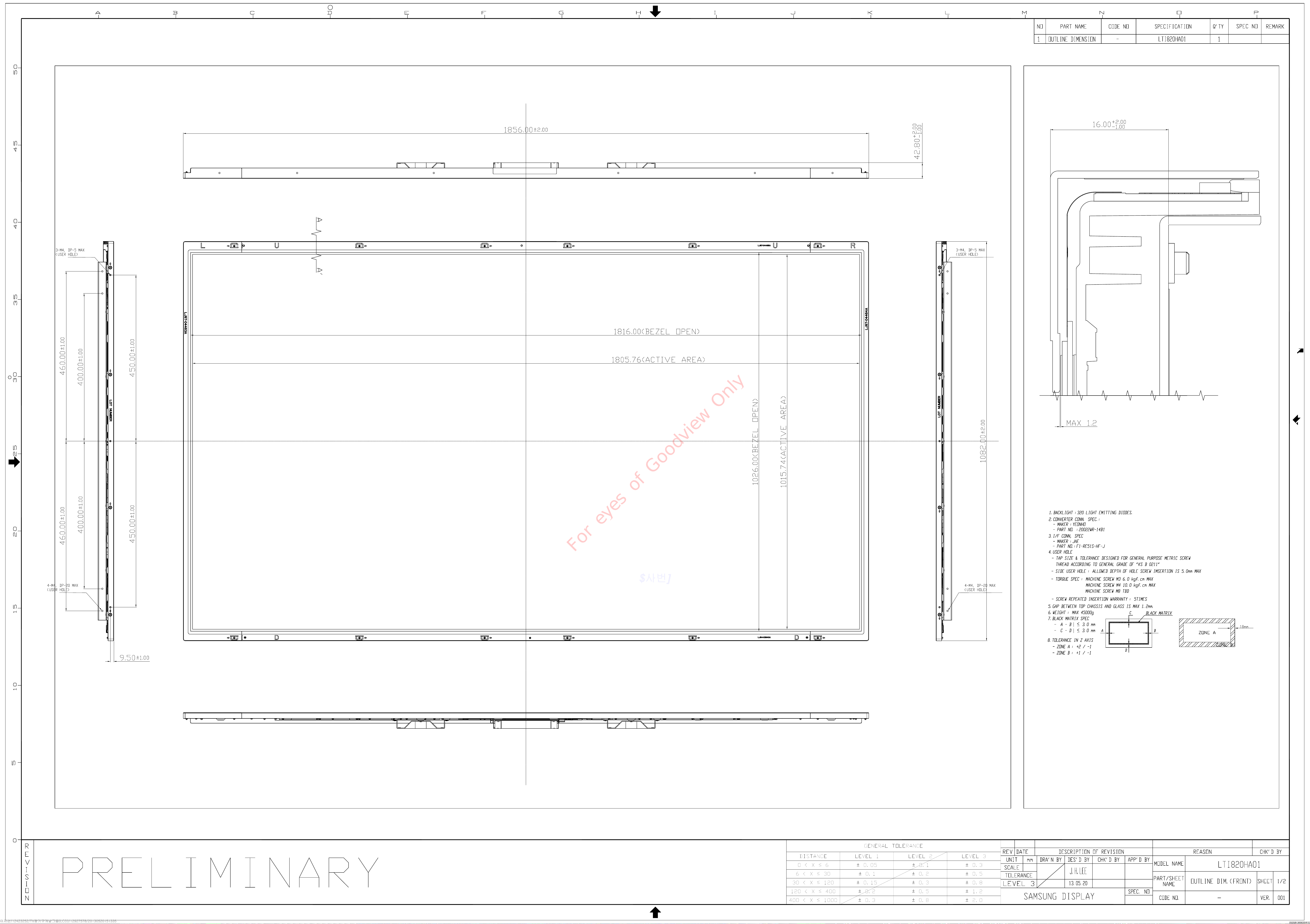
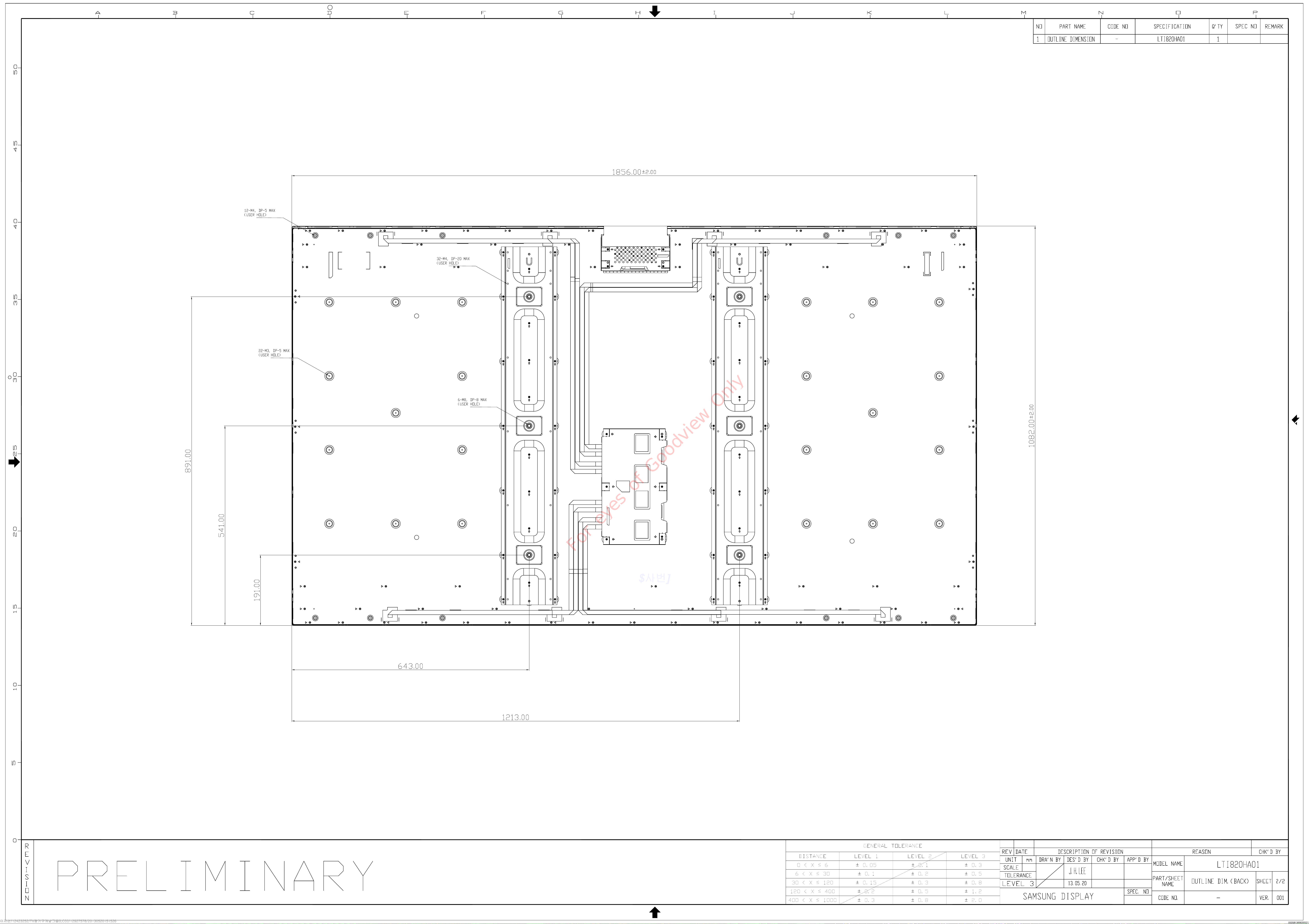
7. OUTLINE DIMENSION
Please refer next 2page.
——————————————————————————————————————————————––—
Doc.No. LTI820HA01-0 Page 24 of 32 Rev.No. 06-001-G-130820
Page 25
For eyes of Goodview Only
Page 26
For eyes of Goodview Only
Page 27
Item
Test condition
Quantity
HTOL
60℃, 500hr determination
8EA
LTOL
0℃, 500hr determination
4EA
HTS
70℃, 500hr determination
4EA
LTS
-25℃, 500hr determination
4EA
THB
50℃ / 90%RH, 500hr determination
10EA
WHTS
60℃ / 75%RH, 500hr determination
4EA
T/S
-20 ~ 60℃, Dwell time : 30Min, 200cycle
4EA
TSS
-20 ~ 65℃, 220cycle
4EA
Image sticking
50℃, Mosaic pattern (9X10), 12hrs
8EA
Contact ESD
±10 kV, 210Point, 1 time/Point
3EA
Air ESD
±20 kV, 210Point, 1 time/Point
3EA
Input Con. ESD
±15kV, Input Con. Pin, 3 times/Pin
3EA
Dust
5sec spray, 5min sedimentation / 5hr(Portrait 10hr),
Power 10min on, 10min off
2EA
Pallet Vibration
Pallet Drop
Pallet vibration : 1.05Grms, 5 ~ 200Hz, 2hr/stack side
Pallet Drop : 20cm, bottom side 2 angles, 1side(Bottom)
1Pallet
Altitude
-40~50℃, 0m(0ft) ~ 13,700m(45,000ft), 72.5Hr
4EA
For eyes of Goodview Only
————————————————————————————————————————————————–
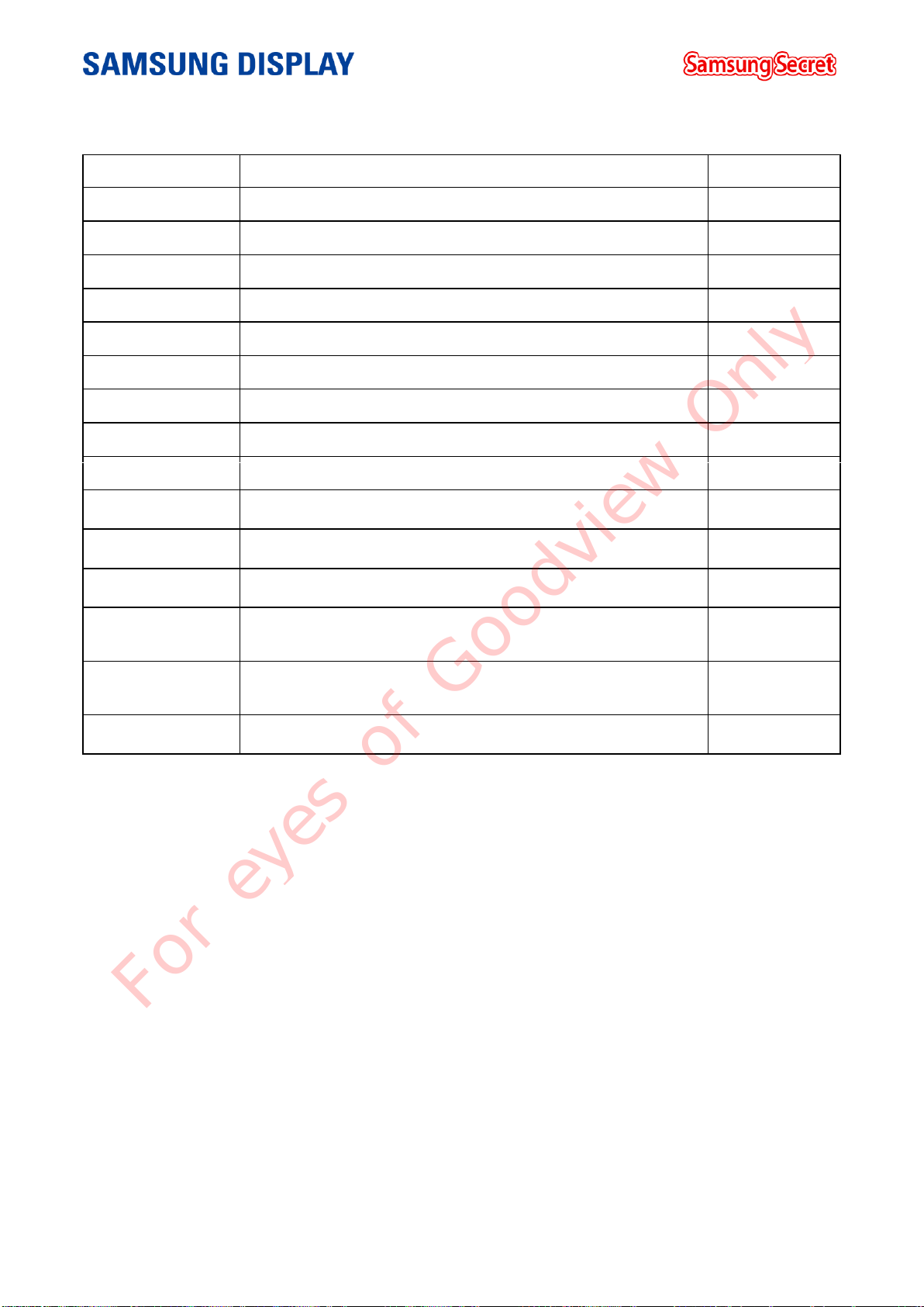
8. RELIABILITY TEST
[ Criteria on evaluation]
The components of product, which may affect to the function of display shall not be changed when the display
quality test is executed under the normal operating condition.
* HTOL / LTOL : The operating at the high and low temperature*
* THB : The slant of temperature and humidity
* HTS / LTS : The storage at the high and low temperature
* WHTS : The storage condition at the high temperature with the high humidity
——————————————————————————————————————————————––—
Doc.No. LTI820HA01-0 Page 27 of 32 Rev.No. 06-001-G-130820
Page 28
No
Part name
Quantity
1
Packing pallet box
1 EA 2 Shielding bag
6 EA
3
Protector panel
6 EA 4 Pallet paper
1 EA
For eyes of Goodview Only
————————————————————————————————————————————————–
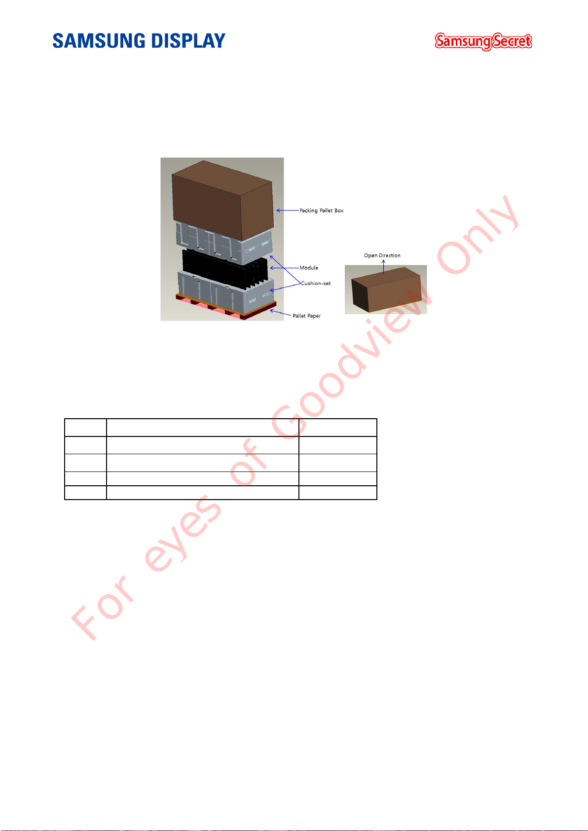
9. PACKING
(1) Packing Form : EPS
(2) Packing Method
Note(1) Total Weight : Approximately 324.9kg [With Pallet Paper]
Note(2) Acceptance number of piling : Move – 1Pallets / Stock – 2Pallets
Note(3) Carton size : 2014mm(H) x 1027mm(V) x 1028mm(Height) [Without Pallet Plastic]
2025mm(H) x 1050mm(V) x 1345mm(Height) [With Pallet Plastic]
(3) Packing Material
——————————————————————————————————————————————––—
Doc.No. LTI820HA01-0 Page 28 of 32 Rev.No. 06-001-G-130820
Page 29
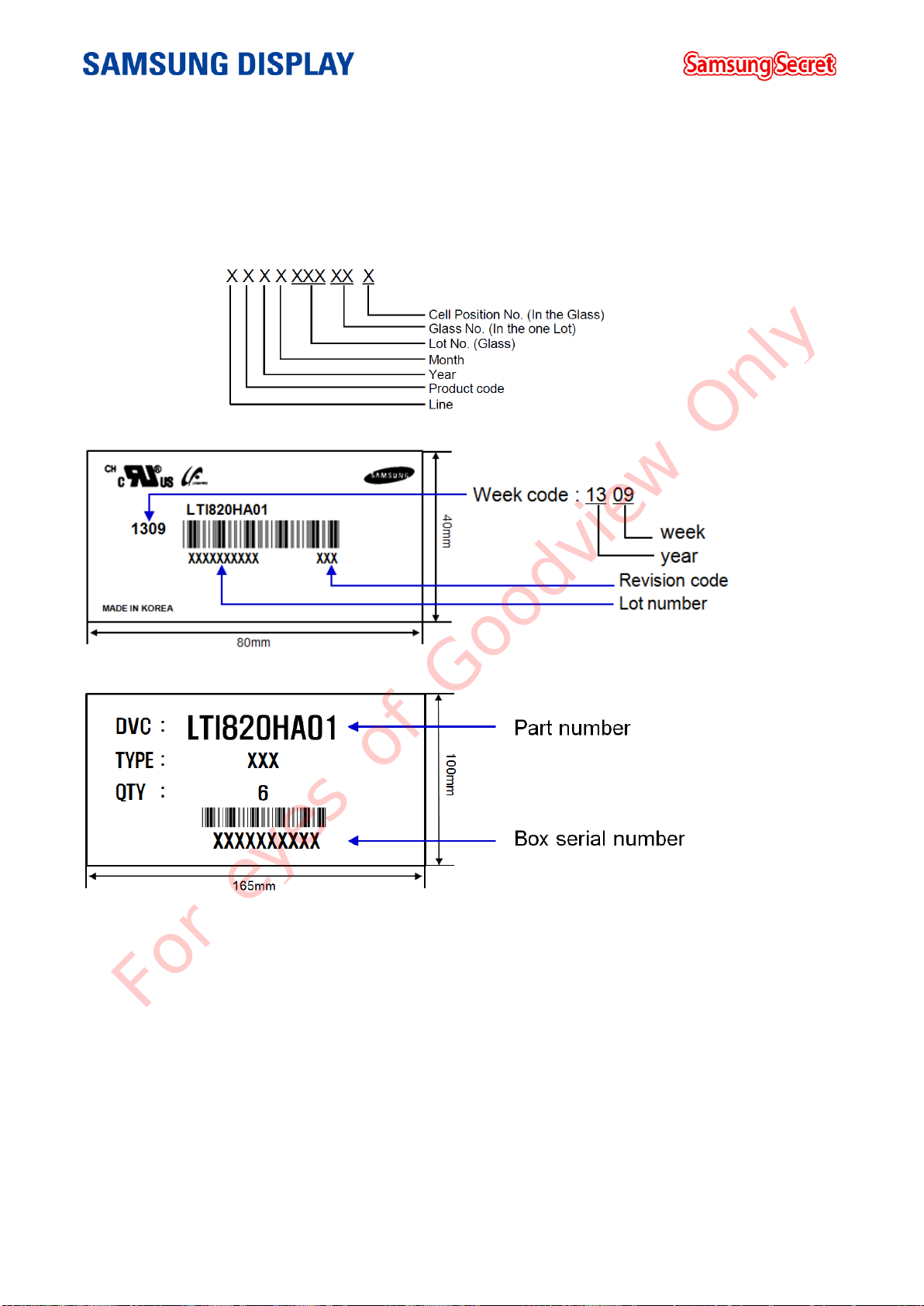
(3) Lot number :
For eyes of Goodview Only
————————————————————————————————————————————————–
10. MARKINGS & OTHERS
A nameplate bearing followed by is affixed to a shipped product at the specified location on each product.
(1) Parts number : LTI820HA01
(2) Revision code : Three letters
(4) Nameplate Indication
(5) Packing small box attach
——————————————————————————————————————————————––—
Doc.No. LTI820HA01-0 Page 29 of 32 Rev.No. 06-001-G-130820
Page 30

For eyes of Goodview Only
————————————————————————————————————————————————–
11. GENERAL PRECAUTIONS
11.1 HANDLING
(a) When the module is assembled, It should be attached to the system firmly using every mounting holes.
Be careful not to twist and bend the modules.
(b) Refrain from strong mechanical shock and / or any force to the module. In addition to damage, this may
cause improper operation or damage to the module and LED back-light.
(c) Note that polarizers are very fragile and could be easily damaged. Do not press or scratch the surface
harder than a HB pencil lead.
(d) Wipe off water droplets or oil immediately. If you leave the droplets for a long time, Staining and
discoloration may occur.
(e) If the surface of the polarizer is dirty, clean it using some absorbent cotton or soft cloth.
(f) The desirable cleaners are water, IPA (Isoprophyl Alcohol) or Hexane. Do not use Ketone type materials
(ex. Acetone), Ethyl alcohol, Toluene, Ethyl acid or Methyl chloride. It might permanent damage to the
polarizer due to chemical reaction.
(g) If the liquid crystal material leaks from the panel, it should be kept away from the eyes or mouth.
In case of contact with hands, legs or clothes, it must be washed away thoroughly with soap.
(h) Protect the module from static. it may cause damage to the C-MOS Gate Array IC.
(i) Use fingerstalls with soft gloves in order to keep display clean during the incoming inspection and assembly
process.
(j) Do not disassemble the module.
(k) Do not pull or fold the LED wire.
(l) Do not touch any component which is located on the back side.
(m) Protection film for polarizer on the module shall be slowly peeled off just before use so that the
electrostatic charge can be minimized.
(n) Pins of I/F connector shall not be touched directly with bare hands.
——————————————————————————————————————————————––—
Doc.No. LTI820HA01-0 Page 30 of 32 Rev.No. 06-001-G-130820
Page 31
ITEM
Unit
Min.
Max.
Storage
Temperature
(℃) 5 40
Storage Humidity
(%rH)
35
75
Storage Life
12 months
Storage Condition
- The storage room should be equipped with a good ventilation facility, which has a
temperature controlling system.
- Products should be placed on the pallet, which is away from the wall not on the floor.
- Prevent products from being exposed to the direct sunlight, moisture, and water.
Be cautious not to pile the products up.
- Avoid storing products in the environment, which other hazardous material is placed.
- If products are delivered or kept in the storage facility more than 3 months, we recommend
you to leave products under the condition including a 20℃ temperature and a humidity of
50% for 24 hours.
- If you store semi-manufactured products for more than 3 months, bake the products under
the condition including the 50℃ temp. and the 10% humidity for 24hrs after being used.
For eyes of Goodview Only
————————————————————————————————————————————————–
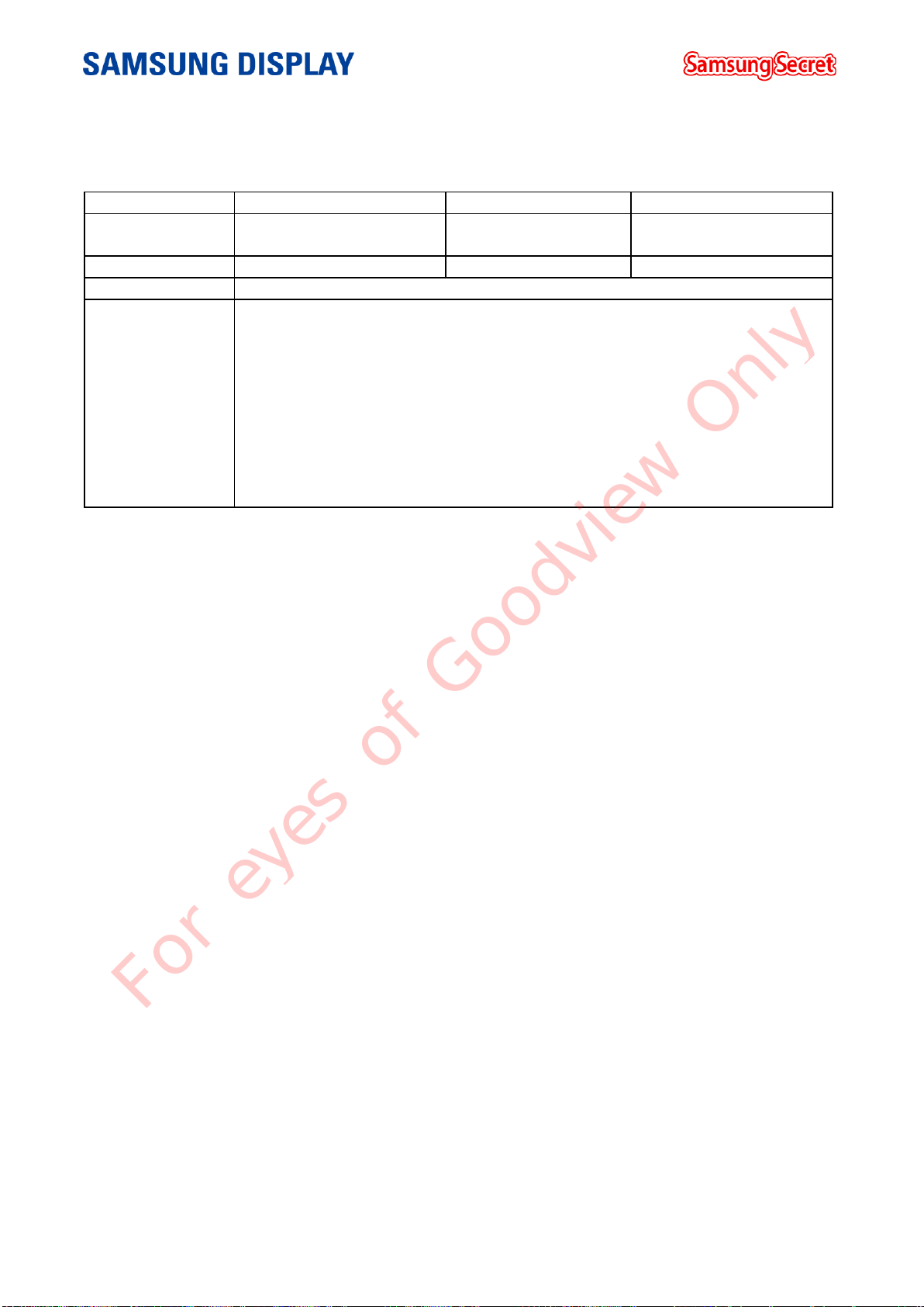
11.2 STORAGE
We highly recommend to comply with the criteria in the table below.
11.3 OPERATION
(a) Do not connect or disconnect the cable to/ from the module at the "Power On" condition.
(b) The power shall be always turned on/off by the item 6.4. "Power on/off sequence".
(c) The module has a circuit with a high frequency. The system manufacturers shall suppress the
electromagnetic interference sufficiently. The methods to ground and shield are important to minimize the
interference.
(d) Design the length of cable to connect between the connector for back-light and the converter as short as
possible and the shorter cable shall be connected directly.
The longer cable between that of back-light and that of converter may cause the luminance of LED to
lower and need a higher startup voltage(Vs).
11.4 OPERATION CONDITION GUIDE
(a) The LCD product should be operated under normal conditions.
Normal condition is defined as below;
- Temperature : 20± 15℃
- Humidity : 55± 20%
- Display pattern : continually changing pattern (Not stationary)
(b) If the product will be used in extreme conditions such as high temperature, humidity, display patterns or
operation time etc.., It is strongly recommended to contact SDC for Application engineering advice.
Otherwise, its reliability and function may not be guaranteed. Extreme conditions are commonly found at
Airports, Transit Stations, Banks, Stock market, and Controlling systems.
——————————————————————————————————————————————––—
Doc.No. LTI820HA01-0 Page 31 of 32 Rev.No. 06-001-G-130820
Page 32

For eyes of Goodview Only
————————————————————————————————————————————————–
11.5 OTHERS
(a) Ultra-violet ray filter is necessary for outdoor operation.
(b) Module should be turned clockwise (regular front view perspective) when used in portrait mode.
(c) Avoid condensation of water. It may result in improper operation or disconnection of electrode.
(d) Do not exceed the absolute maximum rating value. (supply voltage variation, input voltage variation,
variation in part contents and environmental temperature, and so on) Otherwise the Module may be
damaged.
(e) If the Module keeps displaying the same pattern for a long period of time, the image may be "sticked" to
the screen. To avoid image sticking, it is recommended to use a screen saver.
(f) This Module has its circuitry PCB's on the rear side and should be handled carefully in order not to be
stressed.
(g) Please contact SDC in advance when you display the same pattern for a long time.
——————————————————————————————————————————————––—
Doc.No. LTI820HA01-0 Page 32 of 32 Rev.No. 06-001-G-130820
 Loading...