

Samsung LTD121EXSS-01 Datasheet
To: ASUSTeK COMPUTER INC.
This specification is only used for discussing the included items.
You haven’t to approve this specification.
When we shall agree the specification, we will issue the formal one.
SPECIFICATION(TENTATIVE)
www.jxlcd.com
www.jxlcd.com
DATE OF ISSUE: 2007-07-23
PC/Monitor-Use Marketing & Engineering Dept.
Toshiba Matsushita Display Technology Co.,Ltd
1-9-2, Hatara-cho, Fukaya-shi, Saitama, 366-8510, JAPAN
FOR
TFT-LCD MODULE
LTD121EXSS
LTD121EXSS-01
PC&AV-USE LCD Div.

Specification No.
Revision History
Date Rev
No
Sheet
(New)
Item Old New Reason
Sheet 1
www.jxlcd.com
www.jxlcd.com
Toshiba Matsushita Display Technology Co., Ltd.
Date:2007-07-24 New No. LTD121EXSS-01
Date: - - Old No.
←# Special ←& Addition ← Change
Specification No.
Sheet 2
Caution and Handling Precaution
For your end users' safet y, it is strongly ad vised that the items with "(" should be inc luded in the instruction manual of the
system which may be is sued by your organization.
Toshiba Matsushita Display Technology always endeavor to maintain sufficient quality of the LCD panel in process of
designing and manufacturin g, however, to avoid causing extended damages such as accidents resulting in injury or deat h,
fire accidents, or social damages if the LCD panel fails, please adopt safe design as a whole set, by adopting redundant
design, taking measure in set design to prevent fire-spreading, over-current, or incorrect operation, etc.
For Safety
Warning
1) SPECIAL PURPOSES
a) Toshiba Matsushita Display Technology’s Standard LCD modules have not been customized for operation in extreme
environments or for use in applications where performance failures could be life-threatening or otherwise catastrophic.
b) Since they have not been designed for operation in extreme environments, they must never be used in devices that will be
exposed to abnormally high levels of vibration or shock which exceed Toshiba Matsushita Display Technology’s
specification limits.
c) In addition, since Toshiba Matsushita Display Technology’s Standard LCD modules have not be en designed for use in
applications where performance failures could be life-threatening of catastrophic. They must never be installed in aircraft
navigation control systems (such as, but not limited to Traffic Coll ision Avo idance System and Air Traffic Indi cator), in
military defense or weapons systems, in critical industrial process-control systems (e.g., those involved in the production
of nuclear energy), or in critical medical device or p atient life-support systems.
2) ELECTRIC SHOCK
DISCONNECT POWER SUPPLY before handling LCD modules. In order to prevent electric shock, DO NOT TOUCH the
electrode part, cables, connectors, and the LE D circuit part of a module in which LED are built in as a light source of a
backlight or a front light. High voltage is supplied to these parts while power supply is turned on.
1-1 CAUTION
1) *DISASSEMBLING OR MODIFICATION
DO NOT DISASSEMBLE OR MODIFY the modul es.
Sensitive parts inside LCD module may be damaged, and dusts or scratches may mar the displays. Toshiba Matsushita
Display Technology does not warrant the modules, if customer disassembled or modified them.
2) *BREAKAGE OF LCD PANEL
DO NOT INGEST liquid crystal material, DO NOT INHALE this material, and DO NOT PERMIT this material to c ontact the
skin, if glass of LCD panel is broken.
If liquid crystal material contacts the skin, mouth or clothing, take the following actions immediately.
In case contact to the eye or mouth, rinse with la rge amount of running water for more than 15 minutes. In case contact to
the skin or clothing, wipe it off immediately and wash with soa p and larg e am ount of run ning water for mor e than 15 m inut es.
The skin or closing may be damaged if liquid crystal material is left adhered.
In case ingestion, rinse out the mouth well with water. After spewing up by drinking large amount of water, get medical
treatment.
www.jxlcd.com
www.jxlcd.com
Caution
Toshiba Matsushita Display Technology Co., Ltd.
Date:2007-07-24 New No. LTD121EXSS-01
Date: - - Old No.
←# Special ←& Addition ← Change
Specification No.
3) (GLASS OF LCD PANEL
BE CAREFUL WITH CHIPS OF GRASS that may cause injuring fingers or skin, when the glass is broken.
4) ABSOLUTE MAXIMUM RATINGS
DO NOT EXCEED the absolute maximum rating values under the worst probable conditions caused by the supply voltage
variation, input voltage variation, var iation in parts' constants, environmental temperature, etc., other wise LCD module may
be damaged.
5) RECOMMENDED OPERATION CONDITIONS
Don't exceed “the recommended operation conditions” in this specification. (The LCD panel should be used within “the
recommended operation conditions”.)
The performance and quality of the LCD panel are warranted only when the LCD panel is used within “the recommended
operation conditions”. Toshiba Matsushita Display Techn ology never warr ants the performanc e and quality of the LC D panel
when you use the LCD panel over “the recommended operation conditions”, although within “the absolute maximum rating”.
To use the LCD panel over “the recommended operation conditions” may have bad influence on the characteristics and
reliability of the LCD panel and may shorten the life of the LCD panel.
Therefore, when designing the whole set, not to be over “the recommended operation conditions”, you should fully take
care of supply voltage change, characteristic of connection parts, serge of input-and-output line, and surrounding
temperature.
6) POWER PROTECTION CIRCUIT
Employ protection circuit for power supply, whenever the specification specifies it.
A suitable protection circuit should be applied, based on each system design.
DO NOT MODIFY the fuse used in the module. It may cause over heat and/or burning if dusts or metal particles are on the
PCBs in the LCD module.
7) DISPOSAL
Always comply all applicable e nvi ronmental regulations, when disposing of LCD module.
8) EDGES OF PARTS
Be careful with handling the metal flame (bezel) of a module. Even though burr disposal treatment is performed, It may cause
injuring. Be careful with edges of glass parts and touch panel identically. For designing the system, give special consideration
that the wiring and part s do not touch those edges.
9) LCD module’s upper and lower end portions (LED portions) get hot.
The LEDs are built in the upper and lower end portions of LCD module as backlight sources. While LEDs are lit and
immediately after turned off, the face of LCD module (display surface), top and bottom faces, metal portions of right and left
side faces, and metal portion of LED unit cover(s) on the back are hot and require caution.
In case of touching (working on) such portion by necessity, surely disconnect the power to the LCD module beforehand
(refer to page 2, item (2)), protect hands (skin) with low therma l conductive glove s etc. or wait until the te mperatur e of metal
portion gets as low as room temperat ure, and then touch (work on) the portion while being careful to prevent electrostatic
breakdown (refer to page 5, item (2)).
www.jxlcd.com
www.jxlcd.com
Sheet 3
Toshiba Matsushita Display Technology Co., Ltd.
Date:2007-07-24 New No. LTD121EXSS-01
Date: - - Old No.
←# Special ←& Addition ← Change
Specification No.
Sheet 4
For Designing the System
2-1 DESIGNING ENCLOSURE
1) MECHANICAL DIMENSIONS
Refer to the individual specification for LCD module's mechanical dimensions.
2) MOUNTING HOLES
This is a semi-finished product without front bezel. And this LCD module has no mounting holes.
Please contact to your representative or Toshiba Matsushita Display Technologies Co., Ltd. before starting mechanical
design.
3) Handling
When designing module structure or chassis, please conduct a full examination and evaluation internally to prevent troubles
and glass breakage.
As for the glass breakage by cell pressing in the m ar ket, and the dis pla y un eve n ness (poo l ing, ab norm al dis p lay ( whit e sp ot),
etc.) caused by front bezel or ob jects o n front face and back face, Toshiba Mats us hit a Di sp la y T ech nol ogi es C o., Ltd. cannot
deal such problems as our sole responsibility. If such case happens, let us consult with you separately.
4) ¼BENDING / TWISTING
Make sure to design the enclosure that bending/twisting forces are not applied to LCD module during and after the
installation into the system.
Design it so that t he rear side of the LCD modu l e m a y n ev er be pushed by the set and so on. When the rear side of the LCD
module is pushed, a panel is transformed, and that may cause ununiformity on the display.
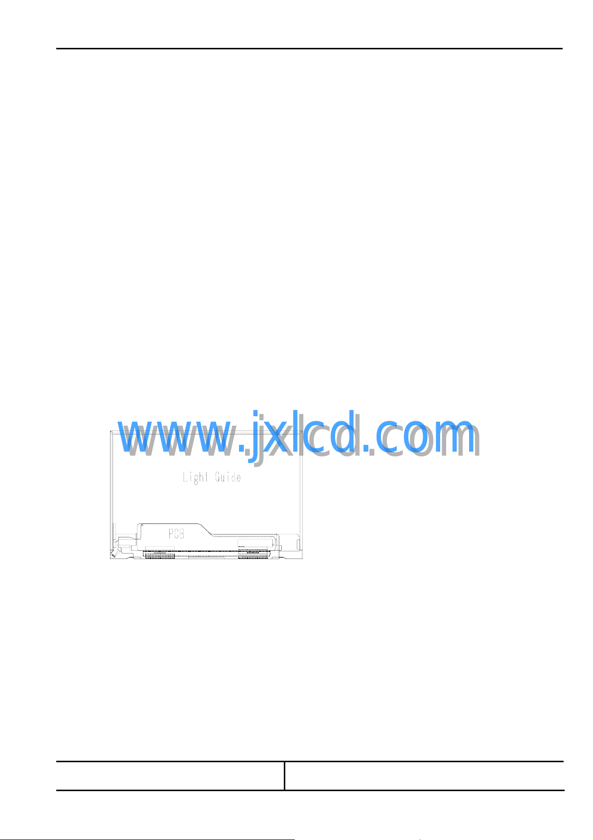
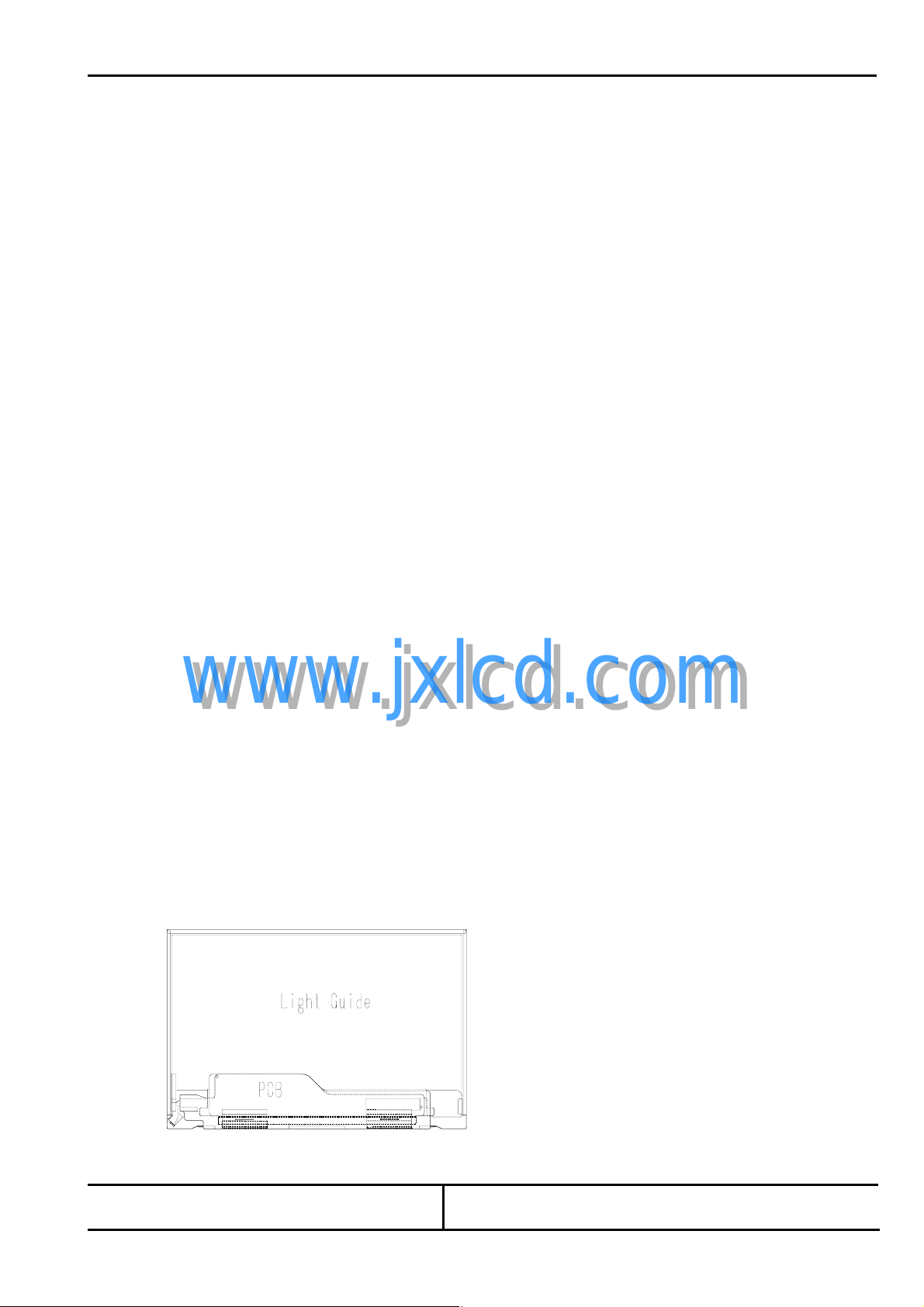
5) DESIGN OF LCD MODULE REAR SURFACE
Design to not touch backside area without obl ique lines area as below.
This LCD module uses light guide. If light guide is pushed, there is danger of appearance of white spot or black spot.
And if circuit board is pushed, there is danger of damage.
6) GASES FROM SETTING MATERIAL
Some plastic materials and shock absorbing materials (rubber) used in the system may generate gases that may cause the
deterioration of the polarizer laminated on LCD’s panel or internal parts of the module. Prior confirmation is required.
7) GASES FROM PACKAGING MATERIAL
Some materials used for packaging (f or which sulf uric acid is used in the rec ycling pr ocess) gener ate gases t hat may caus e
the deterioration of the polarizer laminated on LCD’s panel or internal parts of the module. Prior confirmation is required.
www.jxlcd.com
www.jxlcd.com
Toshiba Matsushita Display Technology Co., Ltd.
Date:2007-07-24 New No. LTD121EXSS-01
Date: - - Old No.
←# Special ←& Addition ← Change
Specification No.
2-2 DESIGNING POWER SUPPLIES AND INPUT SIGNALS TO LCD MODULE
1) CAPACITY OF POWER SUPPLY
Be sure that power supply output fr om the system s hould be limite d to higher values than listed sho wn below. (For example
Quick Arcing Fuse with listed ratings can be used.)
It is because this LCD module explained in this specification has a current limiter, with such function at power input line(s).
But it may be some possibility of overheat and/or burning of LCD module and its periphera l devices before cu rrent limiter of
the module when open-short test of the module is performed by using power supply smaller than following recommended
value.
Power
Supply
VDD 4.0 A 0.5-3.0 A 1.25 A
Refer to individual specification for details for capacity of power supply, and apply some protection circuit including fuses for
power supply lines.
2) SEQUENCE OF POWER SU PP LIES AND INPUT SIGNALS
Power-supply lines should be design ed as follows.
Power supplies should always be turned on before the input signals are supplied to LCD module, and the input signals
should be disconnected before power supplies ar e turned off.
If this sequence is not followed, it may cause mi ss-ope ration of the panel.
Refer to "2.4.2 Sequence of Power Supplies and Signals
In addition, refer to individual specifications for unused terminals.
3) PREVENTION OF IMAGE STICKING
Design the system not to disp lay same pattern for a long time in order to prevent im age sticking on the panel. Note that
incorrect sequence of power supplies and input signal s may cause the sticking on the panel, too.
4) GROUNDING OF METAL FRAME
Grounding of metal frame o f LCD module is generally effective to prevent radiation interference from the system design.
However, the necessity of grounding, or effective grounding me th od should be dependent on each system design.
2-3 DESIGNING FOR BETTER VISIBILITY
1) PANEL ANGLE
Visibility of LCD module deeply depends on the viewing directions. The position and the angle of LCD module in the system
should be designed so that the best visibility can be obtained at the actual usage.
2) WINDOW OPENING
Dimensions of window opening of the system's enclosure should be designed as smaller than "Viewing Area" and larger than
"Active Area" specified in individual specification in order to obtain better appearance.
3) PROTECTIVE COVER
In case of severe environmental condition like outdoor usage, a proper transparent protective cover(lens) over LCD
module is recommended to prevent scratches, invasion of dust, water, etc., between the system housing and LCD module.
It is recommended to apply an Ultra -violet filter (less than 390nm cut) onto the LCD module, for outdoor operation.
Strong ultra-violet radiation may damage the panel. However, in that case, transmittance-luminance will decrease.
Careful selection of material is required.
Don’t expose any parts, except the viewing area, into the direct sunlight , otherwise deterioration may occur.
Recommended maximum
output current of
power supply
www.jxlcd.com
www.jxlcd.com
Recommended Fuse Rating
(in case of using fuse
for current limiter)
Sheet 5
Built-in Fuse Rating
(for reference)
" for the detailed specification.
Toshiba Matsushita Display Technology Co., Ltd.
Date:2007-07-24 New No. LTD121EXSS-01
Date: - - Old No.
←# Special ←& Addition ← Change

Specification No.
Sheet 6
For Installation in Assembly
3-1 CARRYING
Hold metal frame (bezel) when you carry LCD module. Don’t hold FL cable.
3-2 ESD (ELECTRO-STATIC DISCHARGE) PREVENTION
The C-MOS LSIs used in LCD module is very sensitive to ESD. The following caution should be taken when installing LCD
module to an enclosure of the system in order to prevent damage of C-MOS LSIs used in LCD module.
1) HUMIDITY
Ambient humidity of working area is recommended to be higher than 50%RH in order to avoid ESD.
2) GROUNDING
2-1) Grounded electro-conductive mats are recommended to be covered on the floor of working a rea a nd surf ace of workin g
benches.
2-2) The grounding should be done through a resister of 0.5-1M ohms in order to prevent spark of ESD.
2-3) Person handling LCD modules sh oul d be grounded with such as wrist band.
2-4) Tools like screw driver s and working benches should be grou nded.
3) IONIZER
Using ionizer (an antistatic blower) is recommended at working area in order to reduce electro-static voltage.
4) REMOVING PROTECTION FILM
When removing protection film from LCD panel, peel off the film slowly (more than three seconds) from the edge of the panel
with round-ended tweezers or adhesive tape while blowing with ionizer toward the peeling face to minimize ESD which may
damage electrical circuit.
5) Be careful with touching metal portion of testing instruments in order to prevent unnecessary ESD.
6) Do not touch the electrode area of PCB and electrical parts like LSI, capacitor, connector pin, etc.
3-3 DUST AND STAIN PREVENTION
1) WORKING AREA
Reduce dust level in working area. Especially the level of metal particle should be decreased, otherwise electrical circuit in
LCD module may be damaged due to short circuit by me tal particles.
2) PROTECTION FILM
LCD module may be shipped with "protection film" on LCD panel in order to prevent from scratches and dust.
It is recommended to remove the film at later process of assembling.
3) FINGER PRINT
Use finger stalls or soft and dust-free gloves in order to keep clean appearance of LCD module when handled for incoming
inspection and assembly.
4) ¼WIPING OFF DUST ON THE PANEL
When LCD panel becomes dirty, wipe the panel surface off softly with absorbent cotton or another soft cloth.
If necessary, breathe upon the panel surface and then wipe off immediately and softly again.
If the dirt can not be wiped off, follow the instructions described in individual specification.
Be careful not to spill organ ic solvents into the inside of L CD module. The polarizer l aminated to LCD panel and ad hesives
may be invaded by the organic solvents, so do not use any organic solvents for wiping off LCD panel. Driver IC and PCB
area used inside LCD module may be damaged by the solvents.
5) ADHESIVE ON LCD PANEL
Be careful not to attach adhesive, grease, etc., on LCD panel, because it is difficult to remove them without any damages on
LCD panel.
www.jxlcd.com
www.jxlcd.com
Toshiba Matsushita Display Technology Co., Ltd.
Date:2007-07-24 New No. LTD121EXSS-01
Date: - - Old No.
←# Special ←& Addition ← Change
Specification No.
6)(WATER SPOTS ON THE PANEL
Avoid the dewing or water condensation.
Wipe off a spot or spots of water or mist on LCD panel s oftly with absorbent cotton or another cl oth as soon as possible if
happened, otherwise discoloration or stain may be caused. If water invades into LCD module, it may cause LCD module
damages.
7) Gas
Do not expose LCD module to the gas (which is not normally contained in the atmosphere), it may cause mis-operation or
defects.
3-4 BENDING / TWISTING OF LCD MODULE DURING ASSEMBLY
1) INSTALLING LCD MODULE TO THE ENCLOSURE
Do not bend or twist LCD module even momentary when LCD module is installed into an enclosure of the system.
Bending or twisting LCD module may cause its damages.
2) FASTENING SCREWS
Fasten screws for mounting ho le s uniformly, otherwise bending / twisting force may be applied to LCD module.
3) INTERFACE
Do not fasten screws, with catching interface cable or FPC between LCD module and the enclosure.
This may cause bending of LCD module, or become the cause of a failure by damaging cable or FPC.
3-5 MECHANICAL FORCES
1)* STRONG MECHANICAL SHOCK
Refrain from strong mechanical shock like dro pping from the working bench or knocking against hard object.
These may cause panel crack, damage of FL or other miss-operation.
2)* EXCESSIVE FORCE
Refrain from excessive force like pushing the surface of LCD panel and LCD module. This may cause scratches or breakage
of the panel, or a failure of the module.
3)* PRESSURE ON THE PA NEL
Do not put heavy object such as tools, books, etc., and do not pile up LCD modules.
Be careful not to touch surface of th e po lariz er la min ated to th e panel with any h ar d an d s har p obj ect. T he po lari zer is so s oft
that it can be easily scratched, even the protect film covers it.
4)* PRESSURE ON REAR SIDE
Design to not touch backside area without obl ique lines area as below.
This LCD module uses light guide. If light guide is pushed, there is danger of appearance of white spot or black spot.
And if circuit board is pushed, there is danger of damage.
www.jxlcd.com
www.jxlcd.com
Sheet 7
Toshiba Matsushita Display Technology Co., Ltd.
Date:2007-07-24 New No. LTD121EXSS-01
Date: - - Old No.
←# Special ←& Addition ← Change

Specification No.
5) CONNECTORS
When inserting or disconnecting the connectors to LCD module, be sure not to apply force against PCB nor connecting
cables, otherwise internal con nection of PCB and TAB drivers may be damaged.
Do not fasten screws while putting cables like those for interface between LCD module and the enclo su re .
3-6 OPERATION
Be sure that the following caution should be taken under assembly and inspection of the system.
1) POWER SUPPLY
Power supplies should always be turned off in connecting process.
Do not connect or disconnect the power cables and connectors with power applied to LCD module.
This may cause damage of module circuit.
2) INPUT SIGNAL
The signal should be applied after power supplies are turned on.
The signal should be removed before power supplies are turned off.
The detailed sequence of pow er su ppl ies and signals are described in individual specifications.
3) LCD LONG PERIOD OPERATION
In case of LCD long period operation, discoloration of light guide or optical sheet will be happened due to ultra violet and heat
from CCFL. As the result, there is possibility to have out of specification for the optical characteristic as “5.2”.
But this is not irregular phenomena . Mo reover, CCFL also has the characteristic of col or shift by long period operation.
4) LED life
Please note that LED life will be shorter than the average life described in the Specification if the ambient temperature is
higher than 25°C.
When replacing LCD module, turn off supply voltage and in put signal to the LCD module, surely disconnect the power
supply to the circuit for lighting the backlig ht (not on ly by turning off the c ontrol signal to ON/OFF term inal etc.), and then
replace the LCD module.
5) To replace LCD modules, make sure that all power supplies, voltages, input sign als and driver for LED backlight should be
completely turned off (not only to turn off at ON/OFF terminal, but ensure to turn off the power supply completely then
replace LCD modules).
www.jxlcd.com
www.jxlcd.com
Sheet 8
Toshiba Matsushita Display Technology Co., Ltd.
Date:2007-07-24 New No. LTD121EXSS-01
Date: - - Old No.
←# Special ←& Addition ← Change

Specification No.
Sheet 9
For T ransportation and Storage
1) TEMPERATURE
Do not store LCD modules in high temperature, espec ially in high humidity for a long time (approximately more than one
month).
It is strongly recommended to store LCD modules where the temperature is in the range of 0 to 35 degrees Celsius and the
humidity is lower than 70%.
2) LOW TEMPERATURE
Liquid crystal material may be coagulated and LCD panel may be damaged at the lower temperature than storage
temperature range described in individual specification.
3) ULTRA VIOLET RAY
Store LCD module without exposure to direct sunlight or fluorescent lamps in order to prevent the module from strong ultra
violet ray.
4) CLEANLINESS
Keep the module in clean place, because any dust, hard particle may damage the polarizer, or dust invades the inside of the
module.
5) ¼CONDENSATION OF WATER
Avoid condensation of water on LCD module, otherwise it may cause mis-operation or defects. Keep away LCD module from
such ambient.
6) Gas
Among some of cardboards and rubber parts etc. generates corrosive gas, so it is advisable to confirm its reliability on the
whole set or its packed condition.
7) PACKAGING
In case of transportation or storage after opening the original packaging, LCD modules are recommended to be repacked
into the original packagi ng with the same method, especially with same kind of desiccant.
www.jxlcd.com
www.jxlcd.com
Toshiba Matsushita Display Technology Co., Ltd.
Date:2007-07-24 New No. LTD121EXSS-01
Date: - - Old No.
←# Special ←& Addition ← Change

Specification No.
Sheet 10
- CONTENTS -
Revision History Sheet 1
Caution and Handling Precaution 2
1. Scope 11
2. Product Specifications 11
2.1 General Specifications
2.2 Absolute Maximum Ratings
2.3 Mechanical Specifications
2.3.1 Weight
2.3.2 Dimensional Outline
2.4 Electrical Specifications
2.4.1 Circuit Diagram
2.4.2 Sequence of Power Supplies and Signals
2.4.3 Timing Chart
2.4.4 Timing Specifications
2.4.5 Interface Connector
2.4.6 Colors Combination Table
3. Recommended Operating Conditions 21
4. Electrical Characteristics 22
4.1 Test Conditions
4.2 Specifications
5. Optical Characteristics 23
5.1 Test Conditions
5.2 Optical Specifications
6. Quality 24
6.1 Inspection AQL
www.jxlcd.com
www.jxlcd.com
11. Measuring Method 31
6.2 Test Conditions
6.3 Dimensional Outline
6.4 Appearance Test
6.4.1 Test Conditions
6.4.2 Specifications
6.5 Display Quality
6.5.1 Test Conditions
6.5.2 Specifications
6.6 Reliability Test
6.6.1 Test Conditions
6.6.2 Specifications
6.7 Labels
7. Lifetime
7.1 Module
7.2 Lamp
7.2.1 Test Conditions
7.2.2 Specifications
8. Packaging 30
8.1 Carton
9. Warranty 31
10. Regulation 31
11.1 Measuring Systems
11.2 Measur ing Methods
29
Toshiba Matsushita Display Technology Co., Ltd.
Date:2007-07-24 New No. LTD121EXSS-01
Date: - - Old No.
←# Special ←& Addition ← Change
 Loading...