

SAMSUNG LTA520HT-LH3 Specification
Product Information
Product Information
Customer : DATE : 18.Aug.2006
SAMSUNG TFT--
SAMSUNG TFT
SAMSUNG TFT-LCD
MODEL
MODEL
MODEL : LTA520HT-LH3
Any Modification of Specification is not allowed without SEC's Permission.
NOTE :
Customer’’
Customer
LCD
LCD
: LTA520HT--
: LTA520HT
s Approval
s Approval
LH3
LH3
APPROVAED BY
DATE
18.Aug.2006
SIGNATURE
DATE
PREPARED BY
Product Planning Group3, LCD Business
Samsung Electronics Co., LTD.
DATE
18.Aug.2006
1/ 28Page05-000-G-060818Doc. NoLTA520HT-LH3MODEL
Contents
Revision History -------------------------------------------------------------------------------------------- (3)
General Description --------------------------------------------------------------------------------------- (4)
General Information --------------------------------------------------------------------------------------- (4)
1. Absolute Maximum Ratings -------------------------------------------------------------------------- (5)
2. Optical Characteristics --------------------------------------------------------------------------------- (7)
3. Electrical Characteristics ----------------------------------------------------------------------------- (10)
3.1 TFT LCD Module
3.2 Back Light Unit
3.3 Inverter Input & Specification
4. Block Diagram ------------------------------------------------------------------------------------------- (13)
5. Input Terminal Pin Assignment --------------------------------------------------------------------- (14)
5.1 Input Signal & Power
5.2 Inverter Input Pin Configuration
5.3 Inverter Input Power Sequence
5.4 LVDS Interface
5.5 Input Signals, Basic Display Colors and Gray Scale of Each Color
6. Interface Timing ---------------------------------------------------------------------------------------- (19)
6.1 Timing Parameters (DE only mode)
6.2 Timing Diagrams of interface Signal (DE only mode)
6.3 Power ON/OFF Sequence
7. Outline Dimension -------------------------------------------------------------------------------------- (22)
8. Packing --------------------------------------------------------------------------------------------------- (24)
9. Marking & Others --------------------------------------------------------------------------------------- (25)
10. General Precaution ----------------------------------------------------------------------------------- (26)
10.1 Handling
10.2 Storage
10.3 Operation
10.4 Operation Condition Guide
10.5 Others
2/ 28Page05-000-G-060818Doc. NoLTA520HT-LH3MODEL
* Revision History
Date
Aug
18,
2006
Rev.
No
SummaryPage
First issuedall000
3/ 28Page05-000-G-060818Doc. NoLTA520HT-LH3MODEL
General Description
Description
LTA520HT-LH3 is a color active matrix liquid crystal display (LCD) that uses amorphous
silicon TFT(Thin Film Transistor) as switching components. This model is composed of a
TFT LCD panel, a driver circuit and a back light unit. The resolution of a 52.0“ is
1920 x 1080 and this model can display up to 1.07 billion colors with wide viewing angle of
89° or higher in all directions. This panel is intended to support applications to provide a
excellent performance for Flat Panel Display such as Home-alone Multimedia TFT-LCD
TV, Display terminals for AV application products, and High Definition TV (HDTV).
Features
RoHS compliance (Pb-free)
High contrast ratio, high aperture ratio, fast response time
SPVA(Super Patterned Vertical Align) mode
Wide viewing angle (±178°)
High speed response
Wide UXGA (1920 x 1080 pixels) resolution (16:9)
Low Power consumption
Direct Type 28 CCFTs(Cold Cathode Fluorescent Tube)
DE(Data Enable) mode
LVDS (Low Voltage Differential Signaling) interface (2pixel/clock)
General Information
Module Size
1236.0(H
Haze 44% , Hard-coating (3H)Surface Treatment
RGB vertical stripePixel Arrangement
58.5(D
Normally BlackDisplay Mode
) x 719.2(V
TYP
MAX
UnitSpecificationItems
)
TYP
)
mm
g23,000(Max.)Weight
mm0.6(H) x 0.2(W)*3Pixel Pitch
mm1152.0(H) x 648.0(V)Active Display Area
colors10 bit – 1.07BDisplay Colors
pixel1920 x 1080Number of Pixels
cd/㎡500 (Typ.)Luminance of White
Note
±1.0mm
4/ 28Page05-000-G-060818Doc. NoLTA520HT-LH3MODEL
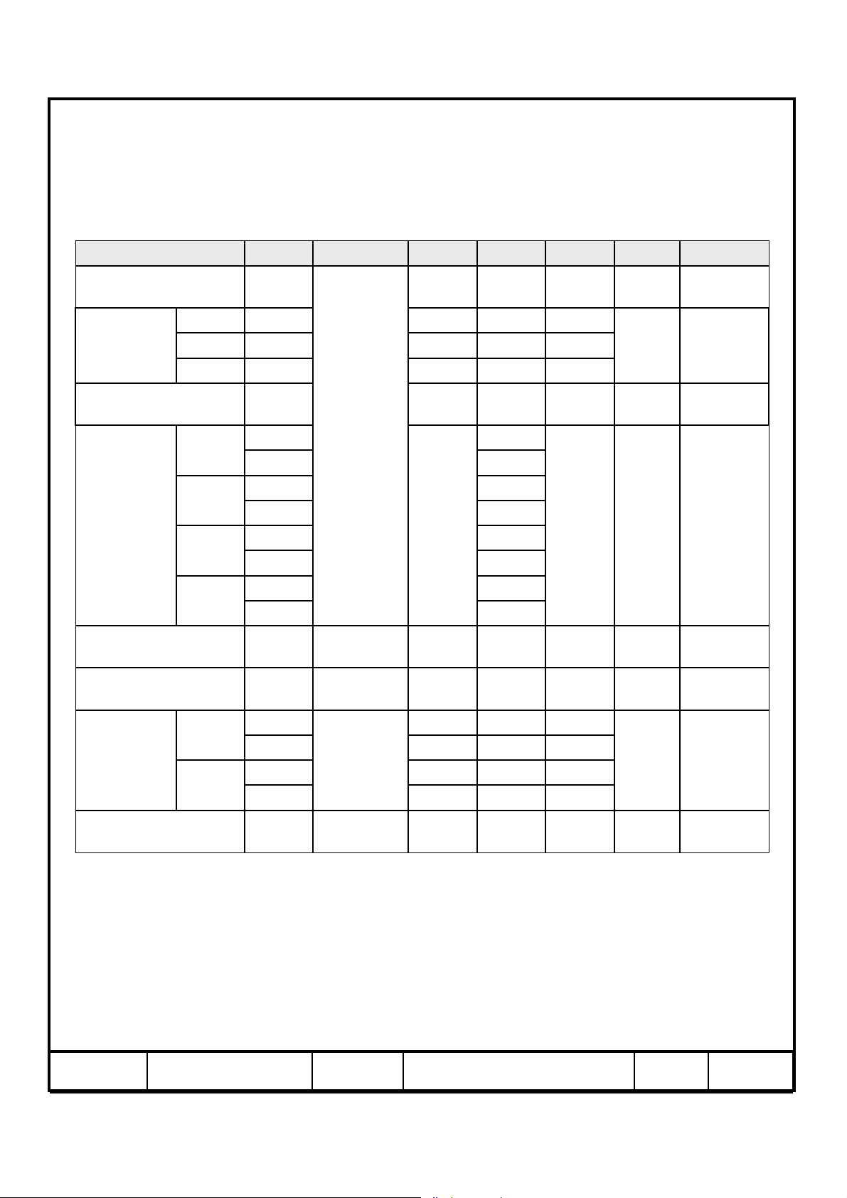
1. Absolute Maximum Ratings
If the condition exceeds maximum ratings, it can cause malfunction or unrecoverable
damage to the device.
NoteUnitMax.Min.SymbolItem
Power Supply Voltage
Storage temperature
Glass surface
Center
DD
STG
OPR
temperature
(Operation)
T. Uniformity
Shock ( non - operating )
Vibration ( non - operating )
Note (1) Ta= 25 ± 2 °C
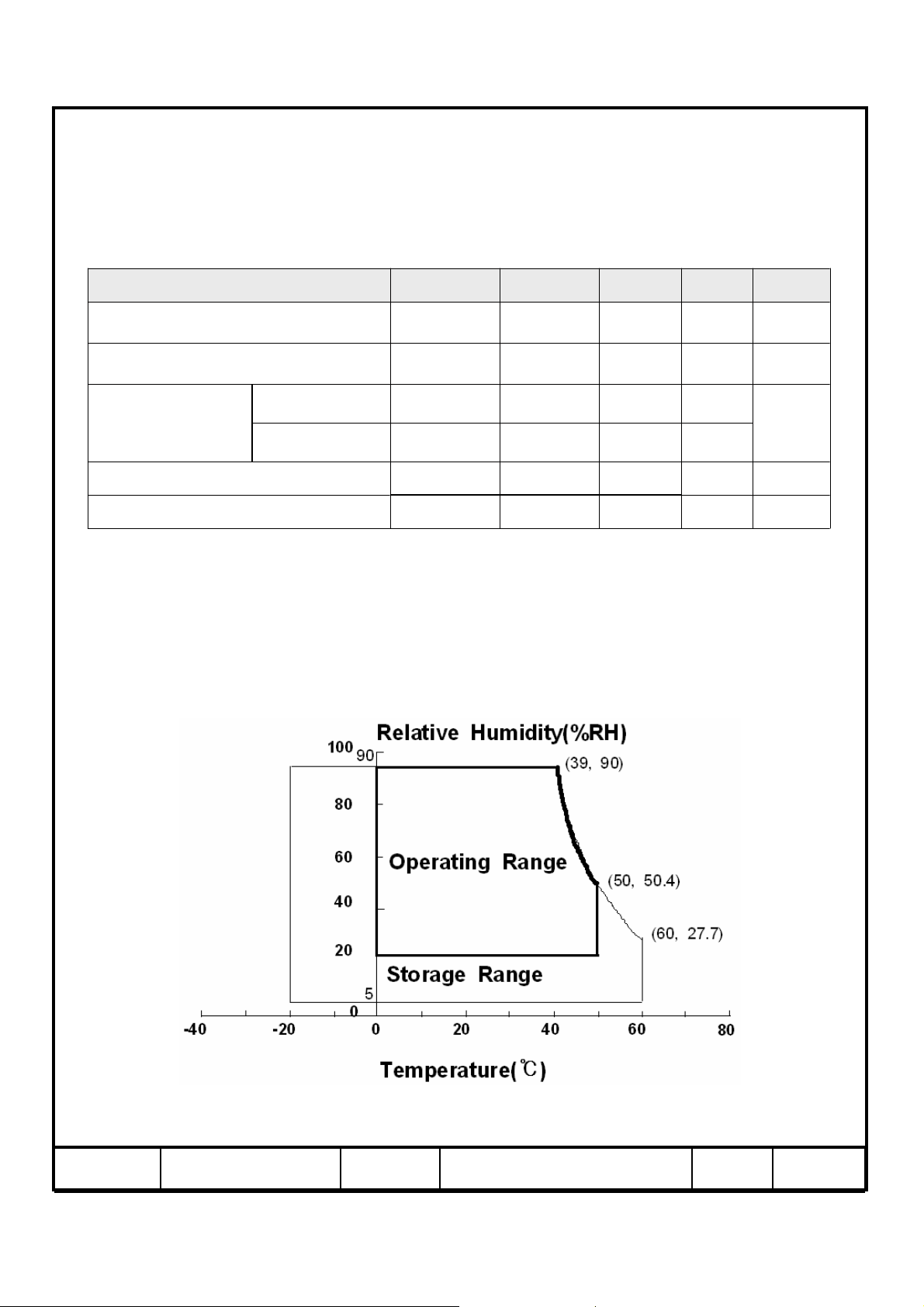
(2) Temperature and relative humidity range are shown in the figure below.
a. 90 % RH Max. (Ta ≤ 39 °C)
b. Relative Humidity is 90% or less. (Ta > 39 °C)
c. No condensation
(3) 11ms, sine wave, one time for ±X, ±Y, ±Z axis
(4) 10-300 Hz, Sweep rate 10min, 30min for X,Y,Z axis
△T
nop
nop
60-20T
500T
10-
30
℃
℃
℃
(1)V13.0GND-1V
(2)
(2),(5)
(3)G-S
(4)G1.5-V
Fig. Temperature and Relative humidity range
5/ 28Page05-000-G-060818Doc. NoLTA520HT-LH3MODEL
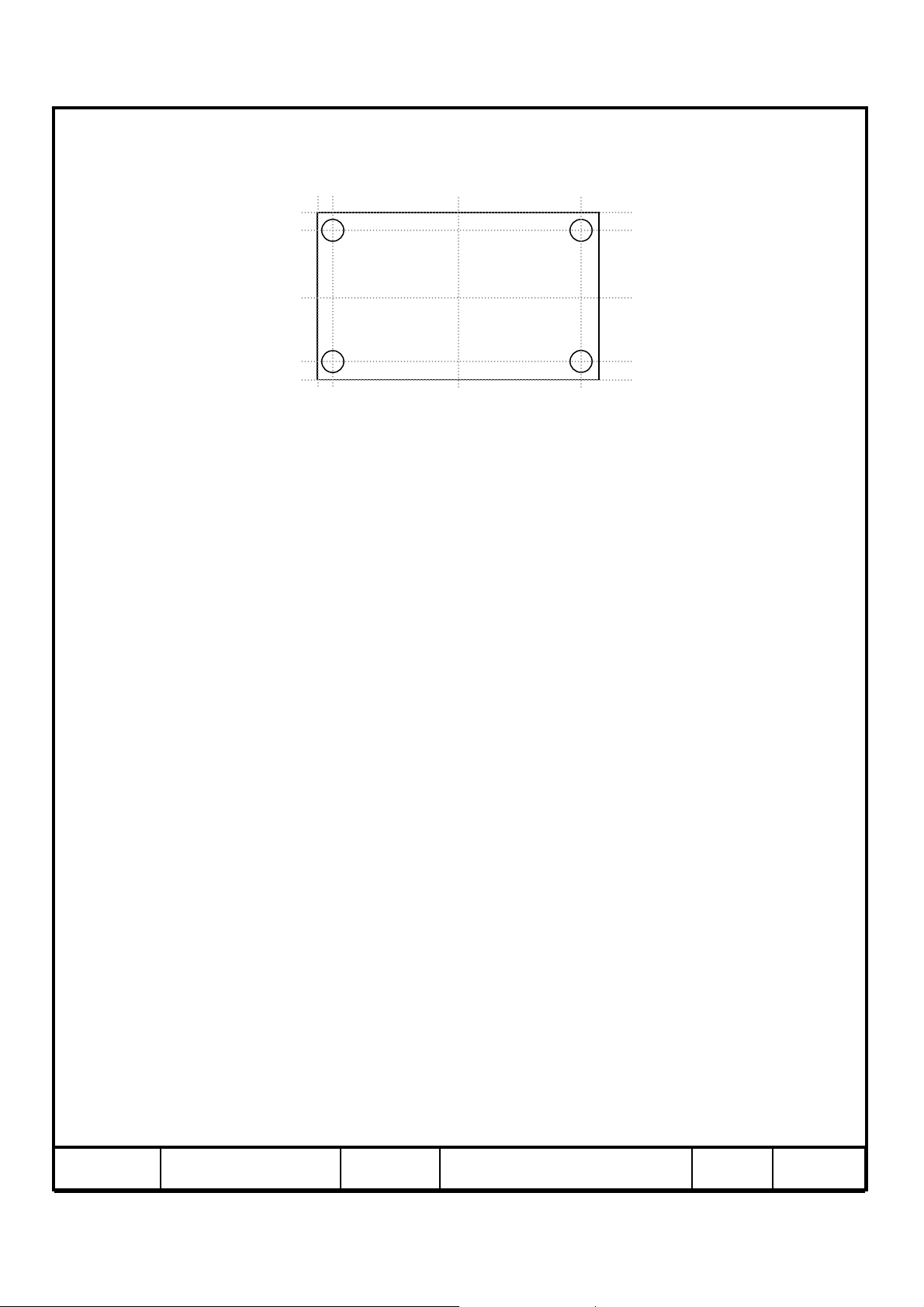
(5) Definition of test point
5mm
5mm
12
5
○
LCD Module (Active)
3
℃
△T should be less than 10
T
: Temperature of the center of the glass surface (Test point 5)
OPR
(△T = | T
OPR–TMAX
T1~ T4 : Temperature of each edge of the glass surface
T
: The highest temperature of the glass surface
MAX
4
| )
6/ 28Page05-000-G-060818Doc. NoLTA520HT-LH3MODEL
2. Optical Characteristics
The optical characteristics should be measured in a dark room or equivalent.
Measuring equipment : TOPCON BM-5A, BM-7,Photo Research PR650
Contrast Ratio
(Center of screen)
Response
Time
Luminance of White
(Center of screen)
Color
Chromaticity
(CIE 1931)
Rising
Falling
Red
Green
Blue
White
(Ta = 25 ± 2°C, VDD=12.0V, fv= 60Hz, f
TgG-to-G
L
Rx
Normal
θL,R=0
θU,D=0
Viewing
Angle
TYP.
-0.03
0.667
0.315Ry
0.200Gx
0.650Gy
0.142Bx
0.080By
0.282Wx
0.294Wy
=148.5MHz, IL= 6.0mArms )
DCLK
NoteUnitMax.Typ.Min.ConditionSymbolItem
-1000800C/R
(3)
BM-5A
1810-Tr
76-Tf
msec
(5)
BM-7
-8-
-500400Y
TYP.
+0.03
cd/m
2
(6)
BM-5A
(7),(8)
PR650
θ
Hor.
Viewing
Angle
Ver.
L
R
U
D
Brightness Uniformity
(9 Points)
uni
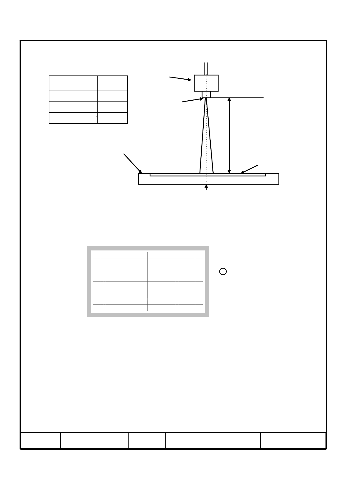
Note (1) Test Equipment Setup
The measurement should be executed in a stable, windless and dark room between
40min and 60min after lighting the back light at the given temperature for stabilization
of the back light. This should be measured in the center of screen.
Single lamp current : 6.0mA
Environment condition : Ta = 25 ± 2 °C
C/R≥10
%-90--Color Gamut
K-10000--Color Temperature
(7)
PR650
(7)
PR650
-8975
-8975θ
Degree
-8975θ
(8)
BM-5A
-8975θ
%25--B
(4)
BM-5A
7/ 28Page05-000-G-060818Doc. NoLTA520HT-LH3MODEL
Field Photo detector
2°BM-5A
2°/1°BM-7
1°PR650
TFT - LCD Module
Note (2) Definition of test point
320 960 1600
Photo detector
Field
The center of the screen
BM-5A : 50㎝
BM-7 : 50㎝
PR650 : 50
㎝
LCD Panel
180
540
900
Note (3) Definition of Contrast Ratio (C/R)
: Ratio of gray max (Gmax) & gray min (Gmin) at the center point ⑤ of the panel
C
/
R =
⑨
⑥
G
max
G
min
Gmax : Luminance with all pixels white
Gmin : Luminance with all pixels black
⑧
⑤④
⑦
①②③
Active Area
Test Point
8/ 28Page05-000-G-060818Doc. NoLTA520HT-LH3MODEL
Note (4) Definition of 9 points brightness uniformity
Buni
BB
=∗
(max min)
100
B
−
max
Bmax : Maximum brightness
Bmin : Minimum brightness
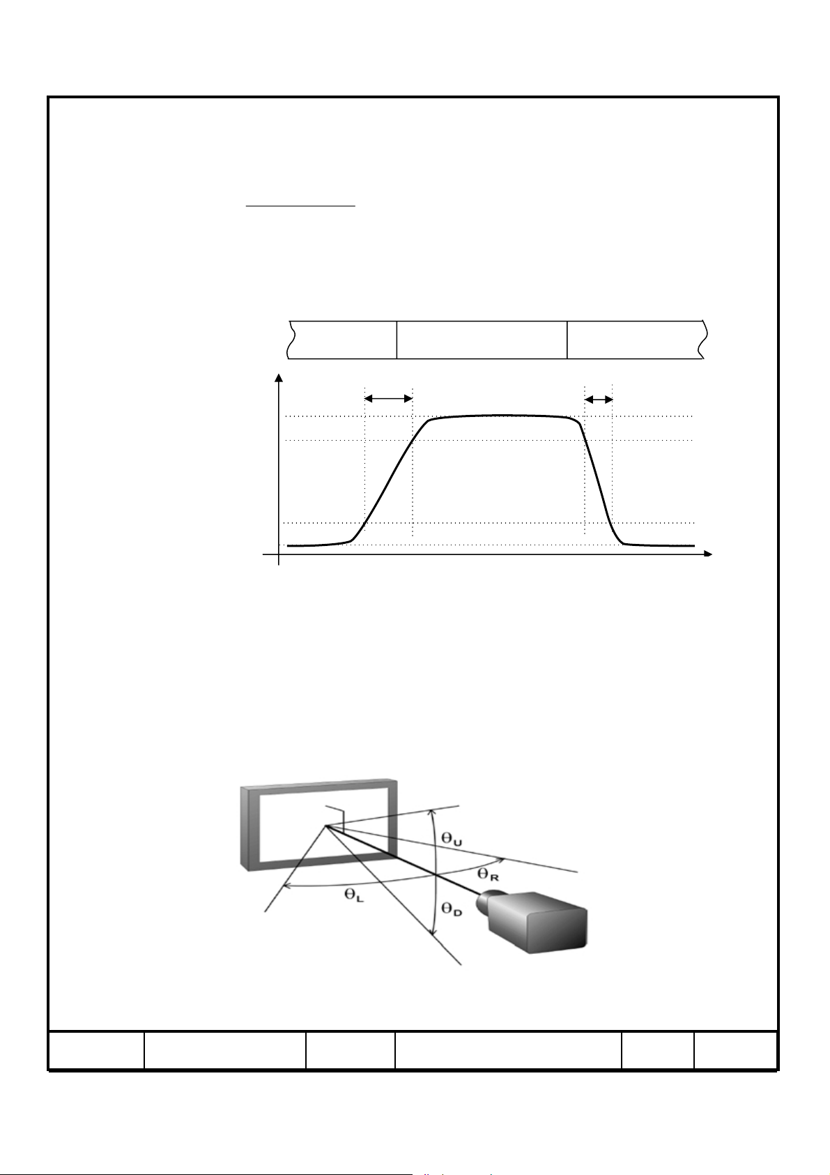
Note (5) Definition of Response time : Sum of Tr, Tf
Display data
Optical Instruments
Response
100%
Black (data off)
T
R
White (data on)
90%
10%
0%
White (data off)
T
F
TIME
Note (6) Definition of Luminance of White : Luminance of white at center point ⑤
Note (7) Definition of Color Chromaticity (CIE 1931)
Color coordinate of Red, Green, Blue & White at center point ⑤
Note (8) Definition of Viewing Angle
: Viewing angle range (C/R ≥10)
9/ 28Page05-000-G-060818Doc. NoLTA520HT-LH3MODEL
 Loading...