

Page 1

LCD-Monitor
Chassis : LEM27DS
Model :
SERVICE
P2770HD
Manual
TFT-LCD Monitor Contents
1. Precautions
2. Product specications
3. Disassembly and Reassemble
4. Troubleshooting
5. Exploded View & Part List
6. Wiring Diagram
P2770HD
Refer to the service manual in the GSPN (see the rear cover) for the more information.
Page 2

Contents
1. Precautions
1-1. Safety Precautions ......................................................................................................... 1-1
1-2. Servicing Precautions ..................................................................................................... 1-2
1-3. Static Electricity Precautions .......................................................................................... 1-2
1-4. Installation Precautions .................................................................................................. 1-3
2. Product specications
2-1. Feature & Specications ................................................................................................. 2-1
2-2. Spec Comparison to the Old Models .............................................................................. 2-3
2-3. Accessories .................................................................................................................... 2-4
3. Disassembly and Assembly
3-1. Disassembly ................................................................................................................... 3-1
4. Troubleshooting
4-1. First Checklist for Troubleshooting ................................................................................ 4-1
4-2. No Power ........................................................................................................................ 4-2
4-3. PC (ANALOG) No Screen ............................................................................................ 4-5
4-4. DVI No Screen ............................................................................................................... 4-8
4-5. HDMI No Screen .......................................................................................................... 4-10
4-6. Faults and Corrective Actions ....................................................................................... 4-13
4-7. Adjustment .................................................................................................................... 4-14
4-8. How to Access Service Mode ....................................................................................... 4-14
4-9. White Balance - Calibration .......................................................................................... 4-16
4-10. White Ratio (Balance) Adjustment ..............................................................................4-18
4-11. Servicing Information .................................................................................................. 4-19
5. Exploded View & Part List
5-1. Exploded View ................................................................................................................ 5-1
5-2. Parts List ......................................................................................................................... 5-3
6. Wiring Diagram
6-1. Wiring Diagram - Main Board ......................................................................................... 6-1
6-2. Wiring Diagram - Main Board ......................................................................................... 6-2
6-3. Connector Functions ...................................................................................................... 6-3
6-4. Cables ............................................................................................................................ 6-3
Page 3
GSPN (Global Service Partner Network)
Area Web Site
North America http://service.samsungportal.com
Latin America http://latin.samsungportal.com
CIS http://cis.samsungportal.com
Europe http://europe.samsungportal.com
China http://china.samsungportal.com
Asia http://asia.samsungportal.com
Mideast & Africa http://mea.samsungportal.com
This Service Manual is a property of Samsung Electronics Co.,Ltd.
Any unauthorized use of Manual can be punished under applicable
International and/or domestic law.
© 2009 Samsung Electronics Co.,Ltd.
All rights reserved.
Printed in Korea
P/N: BN82-00807A-00
Page 4
1. Precautions
1. Precautions
1-1. Safety Precautions
Follow these safety, servicing and ESD precautions to prevent damage and to protect against potential hazards such as
electrical shock.
1-1-1. Warnings
For continued safety, do not attempt to modify the circuit board.1.
Disconnect the AC power and DC power jack before servicing.2.
1-1-2. Servicing the LCD Monitor
When servicing the LCD Monitor, Disconnect the AC line cord from the AC outlet.1.
It is essential that service technicians have an accurate voltage meter available at all times. Check the calibration of 2.
this meter periodically.
1-1-3. Fire and Shock Hazard
Before returning the monitor to the user, perform the following safety checks:
Inspect each lead dress to make certain that the leads are not pinched or that hardware is not lodged between the 1.
chassis and other metal parts in the monitor.
Inspect all protective devices such as nonmetallic control knobs, insulating materials, cabinet backs, adjustment and 2.
compartment covers or shields, isolation resistorcapacitor networks, mechanical insulators, etc.
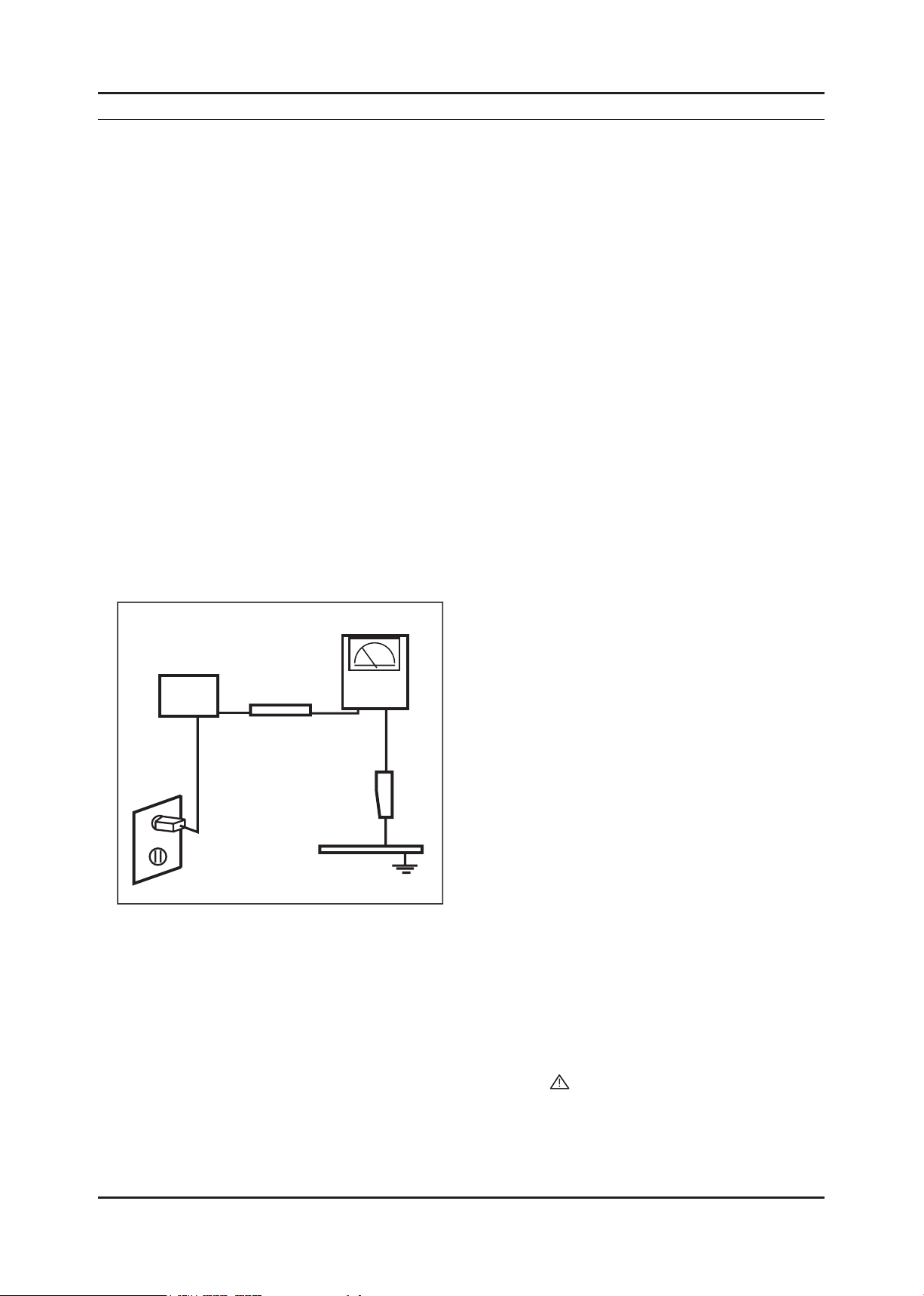
Leakage Current Hot Check (Figure 1-1): 3.
WARNING : Do not use an isolation transformer during this test.
Use a leakage current tester or a metering system that complies with American National Standards Institute (ANSI
C101.1, Leakage Current for Appliances), and Underwriters Laboratories (UL Publication UL1410, 59.7).
(READING SHOULD)
NOT BE ABOVE 0.5mA
DEVICE
UNDER
TEST
2-WIRE CORD
*ALSO TEST WITH
PLUG REVERSED
(USING AC ADAPTER
PLUG AS REQUIRED)
TEST ALL
EXPOSED METAL
SURFACES
LEAKAGE
CURRENT
TESTER
EARTH
GROUND
Figure 1-1. Leakage Current Test Circuit
With the unit completely reassembled, plug the AC line cord directly into a 120V AC outlet. With the unit’s AC switch 4.
rst in the ON position and then OFF, measure the current between a known earth ground (metal water pipe, conduit,
etc.) and all exposed metal parts, including: metal cabinets, screwheads and control shafts.
The current measured should not exceed 0.5 milliamp.
Reverse the power-plug prongs in the AC outlet and repeat the test.
1-1-4. Product Safety Notices
Some electrical and mechanical parts have special safetyrelated characteristics which are often not evident from visual
inspection. The protection they give may not be obtained by replacing them with components rated for higher voltage,
wattage, etc. Parts that have special safety characteristics are identied by on schematics and parts lists. A substitute
replacement that does not have the same safety characteristics as the recommended replacement part might create
shock, re and/or other hazards. Product safety is under review continuously and new instructions are issued whenever
appropriate.
1-1
Page 5

1-2
1. Precautions
1-2. Servicing Precautions
WARNING: An electrolytic capacitor installed with the wrong polarity might explode.
Caution: Before servicing units covered by this service manual, read and follow the Safety Precautions section of
this manual.
Note: If unforeseen circumstances create conict between the following servicing precautions and any of the
safety precautions, always follow the safety precautions.
1-2-1 General Servicing Precautions
Always unplug the unit’s AC power cord from the AC power source and disconnect the DC Power Jack before 1.
attempting to:
(a) remove or reinstall any component or assembly, (b) disconnect PCB plugs or connectors, (c) connect a test
component in parallel with an electrolytic capacitor.
Some components are raised above the printed circuit board for safety. An insulation tube or tape is sometimes 2.
used. The internal wiring is sometimes clamped to prevent contact with thermally hot components. Reinstall all such
elements to their original position.
After servicing, always check that the screws, components and wiring have been correctly reinstalled. Make sure that 3.
the area around the serviced part has not been damaged.
Check the insulation between the blades of the AC plug and accessible conductive parts (examples: metal panels, 4.
input terminals and earphone jacks).
Insulation Checking Procedure: Disconnect the power cord from the AC source and turn the power switch ON. 5.
Connect an insulation resistance meter (500 V) to theblades of the AC plug.
The insulation resistance between each blade of the AC plug and accessible conductive parts (see above) should be
greater than 1 megohm.
Always connect a test instrument’s ground lead to the instrument chassis ground before connecting the positive lead; 6.
always remove the instrument’s ground lead last.
1-3. Static Electricity Precautions
Some semiconductor (solid state) devices can be easily damaged by static electricity. Such components are commonly
called Electrostatically Sensitive Devices (ESD). Examples of typical ESD are integrated circuits and some eld-effect
transistors. The following techniques will reduce the incidence of component damage caused by static electricity.
Immediately before handling any semiconductor components or assemblies, drain the electrostatic charge from your 1.
body by touching a known earth ground. Alternatively, wear a discharging wrist-strap device. To avoid a shock hazard,
be sure to remove the wrist strap before applying power to the monitor.
After removing an ESD-equipped assembly, place it on a conductive surface such as aluminum foil to prevent 2.
accumulation of an electrostatic charge.
Do not use freon-propelled chemicals. These can generate electrical charges sufcient to damage ESDs.3.
Use only a grounded-tip soldering iron to solder or desolder ESDs.4.
Use only an anti-static solder removal device. Some solder removal devices not classied as “anti-static” can generate 5.
electrical charges sufcient to damage ESDs.
Do not remove a replacement ESD from its protective package until you are ready to install it. Most replacement ESDs 6.
are packaged with leads that are electrically shorted together by conductive foam, aluminum foil or other conductive
materials.
Immediately before removing the protective material from the leads of a replacement ESD, touch the protective 7.
material to the chassis or circuit assembly into which the device will be installed.
Caution: Be sure no power is applied to the chassis or circuit and observe all other safety precautions.
Minimize body motions when handling unpackaged replacement ESDs. Motions such as brushing clothes together, 8.
or lifting your foot from a carpeted oor can generate enough static electricity to damage an ESD.
Page 6

1-3
1. Precautions
1-4. Installation Precautions
For safety reasons, more than two people are required for carrying the product.1.
Keep the power cord away from any heat emitting devices, as a melted covering may cause re or electric shock.2.
Do not place the product in areas with poor ventilation such as a bookshelf or closet. The increased internal 3.
temperature may cause re.
Bend the external antenna cable when connecting it to the product. This is a measure to protect it from being exposed 4.
to moisture. Otherwise, it may cause a re or electric shock.
Make sure to turn the power off and unplug the power cord from the outlet before repositioning the product. Also check 5.
the antenna cable or the external connectors if they are fully unplugged. Damage to the cord may cause re or electric
shock.
Keep the antenna far away from any high-voltage cables and install it rmly. Contact with the highvoltage cable or the 6.
antenna falling over may cause re or electric shock.
When installing the product, leave enough space (10cm) between the product and the wall for ventilation purposes. 7.
A rise in temperature within the product may cause re.
Page 7

1. Precautions
Memo
1-4
Page 8

2. Product specications
2. Product specications
2-1. Feature & Specications
Feature
Supreme Digital Interface & Networking ሪ
- With a built-in HD digital tuner, it supports HD broadcasting with no particular set-top box and provides simple
access with a single remote control.
Excellent Picture Quality ሪ
Dynamic Contrast ሪ
- Automatically detects the input visual signal and adjusts to create optimum contrast.
DTV Tuner, HDMI, Stereo, Dolby Digital support ሪ
Convenience ሪ
-The TV utilizes the HDMI system to implement perfect digital sound and picture quality.
Specications
Item Description
Model P2770HD
LCD Panel TFT-LCD Panel, RGB Vertical stripe, normally White,
27-Inch viewable, 0.3114(H) X 0.3114(V) mm Pixel Pitch
Scanning Frequency Horizontal : 30 kHz ~ 81 kHz (Automatic)
Vertical: 56 Hz ~ 75 Hz(Automatic)
Display Colors 16.7 Million colors
Maximum resolution
Input Signal Analog 0.7 Vp-p ±5% positive at 75Ω, internally terminated
Input Sync Signal Type : Seperate H/V
Maximum Pixel Clock rate 138.5 MHz
Active Display
(Horizontal/Vertical)
AC power voltage &
Frequency
Power Consumption 51W < 2W
Dimensions Set
(W x H x D)
Weight Set
(After installation Stand)
TV System Tuning : Frequency Synthesize
667.0mm X 422.0mm X 66.0mm (Without Stand)
667.0mm X 484.0mm X 244.0 mm (With Stand)
Horizontal: 1920pixels
Vertical: 1080pixels
Level : TTL level
597.89(H) X 336.31(V)
AC 110 ~ 240V, 50 ~ 60 Hz
8.2kg (Product) / 11.8kg (Packing)
Environmental
Considerations
System : PAL,NTSC443, SECAM
Sound : MONO, STEREO, NICAM
Operating Temperature: 50˚C ~ 104˚F(10˚C ~ 40˚C)
Operating Humidity : 10% ~ 80%
Storage Temperature: -4˚C ~ 113˚C(-20˚C ~ 45˚C)
Storage Humidity: 5% ~ 95%
2-1
Page 9

2-2
2. Product specications
Specications
Item Description
Model P2770HD
Antenna Input 75Ω
Sound Characteristic -MAX Internal speaker Out : Right : 3W / Left : 3W
-BASS Control Range : -8 dB ~ + 8dB
-TREBLE Control Range : -8 dB ~ +8 dB
-Headphone Out : 10 mW MAX
-Output Frequency : RF : 80 Hz ~ 15 kHz
A/V : 80 Hz ~ 20 kHz
Page 10

2-3
2. Product specications
2-2. Spec Comparison to the Old Models
Model
Design
Screen Size 27” 23”
Resolution 1920X1080 (FHD) 60Hz 1920X1080 (FHD) 60Hz
Brightness 300cd/m2 300cd/m2
Contrast Ratio 1000:1 1000:1
Response Time 5ms 5ms
Viewing Angle Left/Right/Up/Down : 80˚/80˚/80˚/80˚ Left/Right/Up/Down : 80˚/80˚/80˚/80˚
PC Input D-SUB, DVI D-SUB, DVI
Ecot-MFM
P2770HD
CREAM-MFM
2333HD
Power Consumption 51W 54W
DPMS Less than 2W Less than 2W
Sound Output 3W x 2 3W x 2
Dynamic Contrast Ratio 50000:1 10000:1
Sound Effect
Image Size : If the resolution is not wide resolution, this option allows the screen size to be selected as normal or wide.
Dolby Digital Plus,
SRS TruSurround HD
Dolby Digital
Page 11
2. Product specications
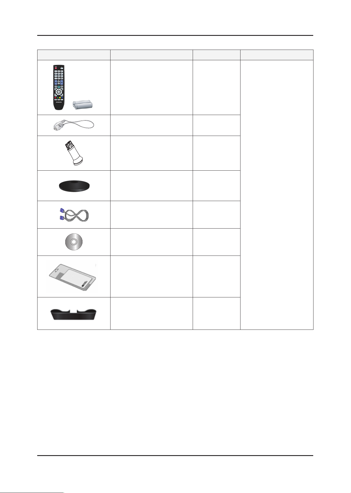
2-3. Accessories
Product Description Ccde. No Remark
Remote Control
&
Batteries (AAA x 2)
Power Cord 3903-000452
Stand Body BN96-09628C
Stand Base BN96-11315A
BN59-00865A
Samsung Electronics
Service center
D-Sub Cable BN39-00244G
User’s Guide,
Monitor Driver,
Natural Color Pro Software
Cleaning Cloth BN63-01798B
Holder-Cable BN96-06529A
BN59-00910C
2-4
Page 12
3. Disassembly and Assembly
3. Disassembly and Assembly
This section describes the disassembly and reassembly sequences for this monitor.
Warning: As this monitor has parts that are sensitive to static electricity, be careful when handling them.
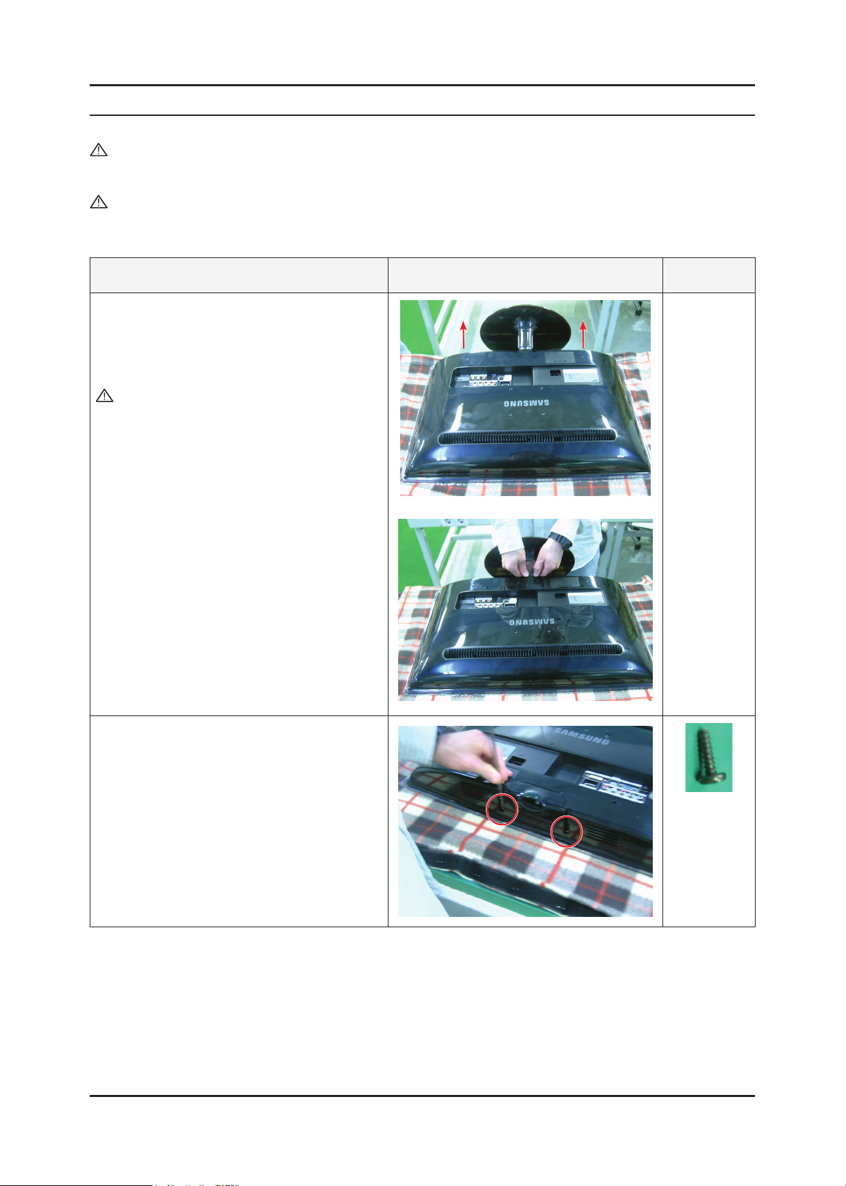
3-1. Disassembly
Caution: 1. Turn the monitor off before beginning the disassembly process.
2. When disassembling the monitor, do not use any metal tools except for the provided jig.
3. Remove the signal cable and the power cord before beginning the disassembly.
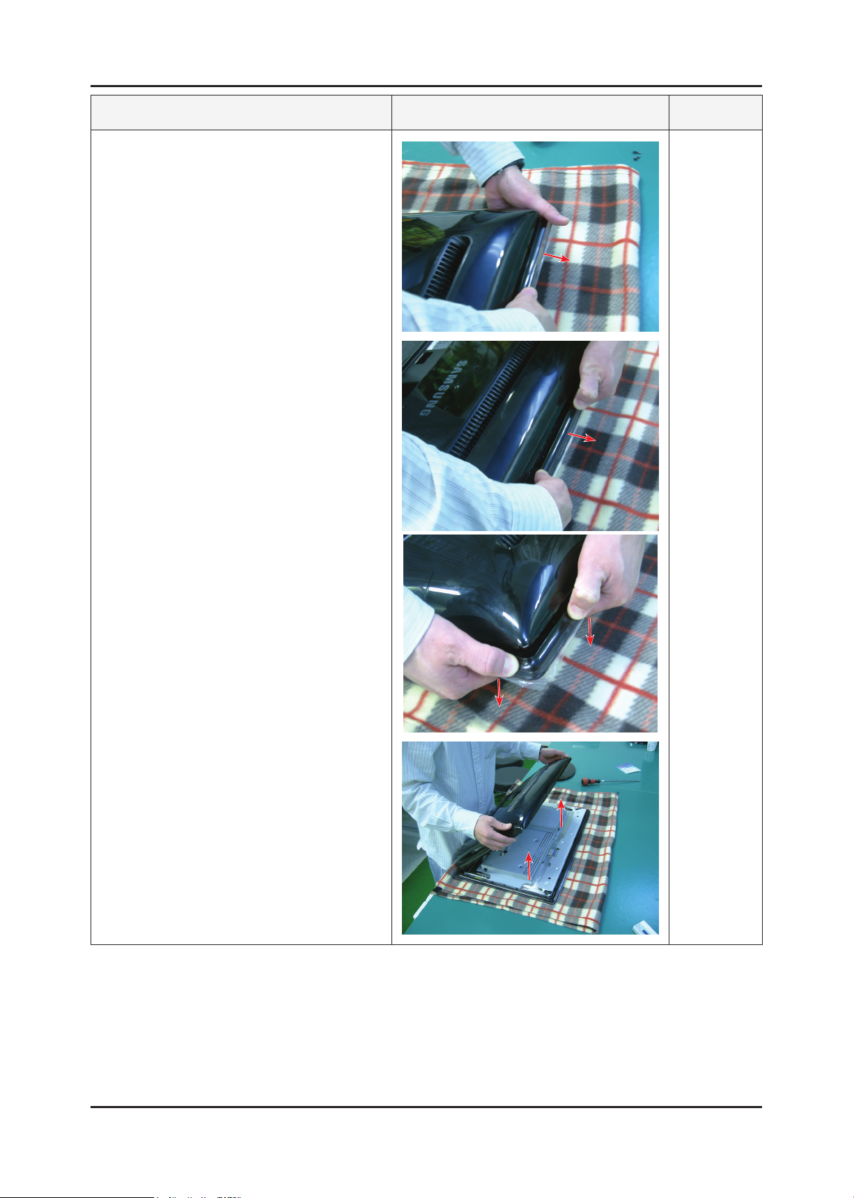
Description Photo Screws
1. Place the monitor face downwards on a soft
blanket or cushion as shown in the picture on
the right. Move the stand from side to side to
disassemble it.
Caution : Do not disassemble with excessive
force. This may break the transparent
stand-bar.
2. Remove the two (2) screws at the bottom.
3-1
Page 13
3-2
3. Disassembly and Assembly
Description Photo Screws
3. Hold the Front-Cover by its corners and push
it downwards. In the same manner, push down
on the other corners, lift the Rear-Cover, and
disassemble it as shown in the picture below.
Page 14
3-3
3. Disassembly and Assembly
Description Photo Screws
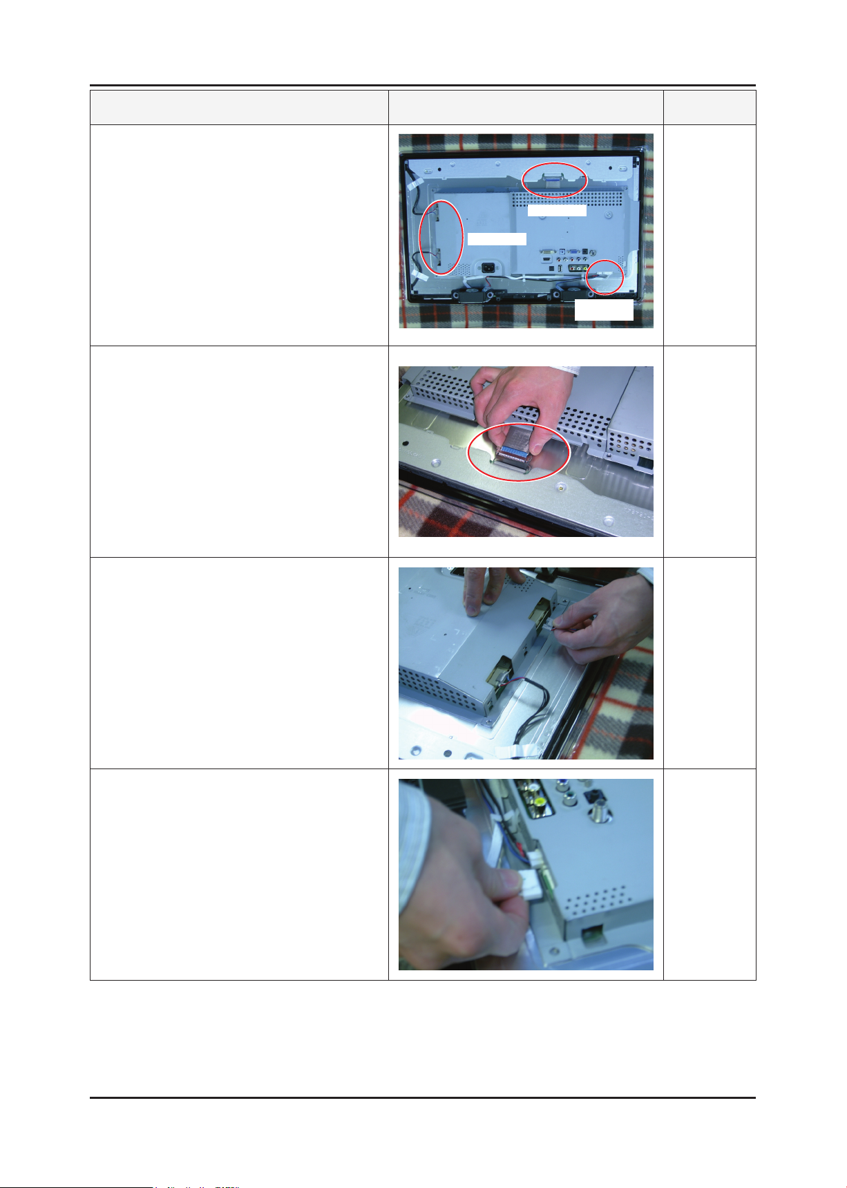
4. After disassembling the Rear-Cover, prepare for
the internal disassembly as shown in the picture
on the right.
5. Remove the LVDS cable.
LAMP WIRE
LVDS
Function &
SPK Wire
6. Remove the Lamp wire.
7. Remove the Function & SPK wires.
Page 15
3. Disassembly and Assembly
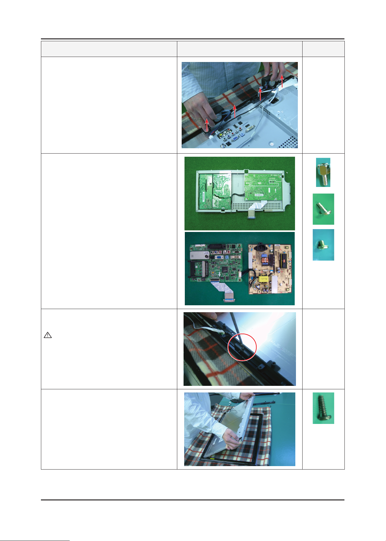
Description Photo Screws
8. Remove the SPK upwards.
9. Remove the Assy Shield-Cover.
Disassemble the PCB inside the Assy.
10. Remove the Holder-Boss from the Assy FrontCover.
Caution : It is difcult disassembling the panel
without removing the screws.
Make sure to remove the screws before
removing the Holder-Boss.
11. Disassemble the panel.
※ Reassembly procedures are in the reverse order of disassembly procedures.
3-4
Page 16

4. Troubleshooting
4. Troubleshooting
4-1. First Checklist for Troubleshooting
Self-Test Feature Check
Your monitor provides a self test feature that allows you to check whether your monitor is functioning properly.
Turn off both your computer and the monitor. 1.
Unplug the video cable from the back of the computer2.
Turn on the monitor. 3.
If the monitor is functioning properly, you will see a box in the illustration below. .
This box appears during normal operation if the video cable becomes disconnected or damaged.
4. Turn off your monitor and reconnect the video cable; then turn on both your computer and the monitor.
If your monitor screen remains blank after using the previous procedure, check your video controller and
computer system; your monitor is functioning properly.
Warning Messages
If there is something wrong with the input signal, a message appears on the screen or the screen goes blank although the
power indicator LED is still on. The message may indicate that the monitor is out of scan range or that you need to check
the signal cable.
Environment
The location and the position of the monitor may inuence the quality and other features of the monitor.
If there are any sub woofer speakers near the monitor, unplug and relocate the woofer to another room.
Remove all electronic devices such as radios, fans, clocks and telephones that are within 3 feet (one meter) of the monitor.
Useful Tips
▶ A monitor recreates visual signals received from the computer.
Therefore, if there is trouble with the computer or the video card, this can cause the monitor to become blank,
have poor coloring, noise, Video mode not supported, etc. In this case, rst check the source of the problem,
and then contact the Service Center or your dealer.
▶ Judging the monitor’s working condition
If there is no image on the screen or a “Not Optimum Mode”, “Recommended Mode 1920 X 1080 60Hz” message
comes up, disconnect the cable from the computer while the monitor is still powered on.
- If there is a message coming up on the screen or if the screen goes white, this means the monitor is in working
condition.
- In this case, check the computer for trouble.
4-1
Page 17

4-2
4. Troubleshooting
4-2. No Power
Symptom
Major
checkpoints
The LED on the front panel of the monitor does not work when the power is connected and the Power button is pressed.
Check if the Power switch on the rear panel of the monitor has been turned on. -
Check the SMPS fuse and the IP-Board output power. -
Check the connection between the IP-Board and the Main Board inside the monitor. -
Check the power part of the Main Board and check if a similar symptom appears at another output terminal.
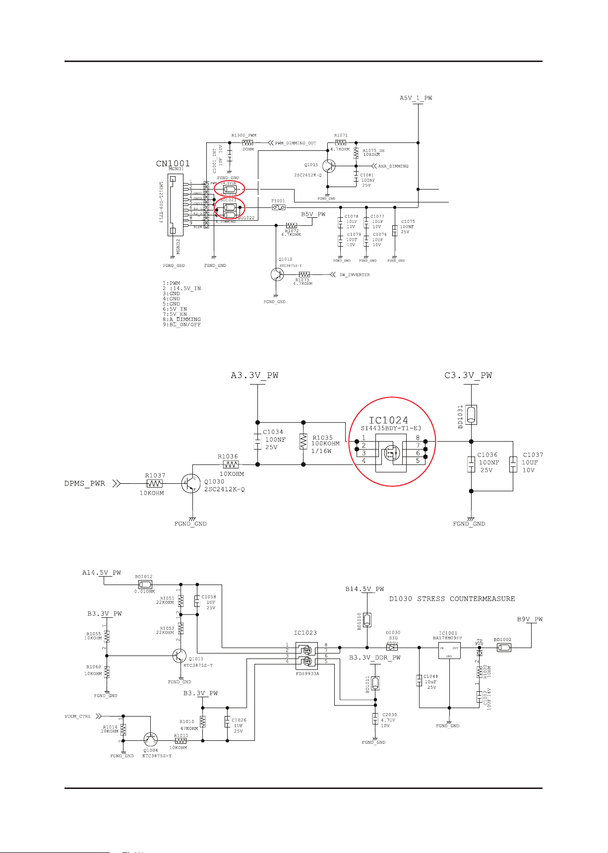
CN1001
IC1023
IC4010
Diagnostics
Does proper 14.5V appear at pin
No. 2 of CN1001? ①
Does proper 5V appear at pin No.
6 and 7 of CN1001? ②
Yes
Does proper 14.5V appear at
BD1013? ①
Does proper 5V appear at
BD1021? ②
Yes
Does proper 3.3V appear at pin
No.1 of IC1024? ②
Yes
Does proper 14.5V appear at
IC1023? ③
Yes
Change main board for
Scaler(IC4010) problem
Main Board Front
No
No
No
No
Check IP Board
Check related circuit of CN1001.
Check related circuit of IC1024.
Check related circuit of IC1022.
Caution Make sure to disconnect the power before working on the IP board.
Page 18
4-3
4. Troubleshooting
4-2-1. Circuit diagrams when the power does not turn on
Page 19
4-4
4. Troubleshooting
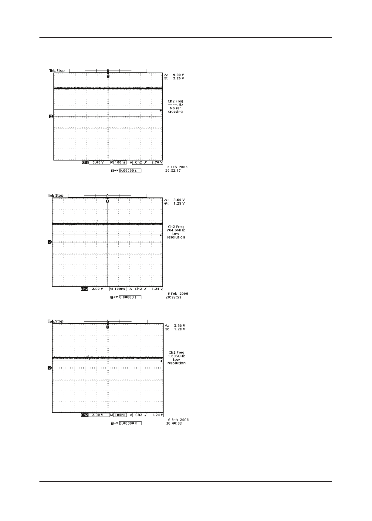
4-2-2. Waveforms
①
②
③
Page 20

4-5
4. Troubleshooting
4-3. PC (ANALOG) No Screen
Symptom
Major
checkpoints
The LED power is on but no picture is displayed on the screen when the D-SUB cable is connected
Even though the LED power turns on, the screen is blank when connecting the VGA cable. -
Check the D-sub cable connections. -
Check whether the LVDS cable is connected correctly to the panel. -
Check whether the lamp connector of the panel is connected correctly to the IP board. -
CN1005
CN8003
Main Board Front
Diagnostics
Caution Make sure to disconnect the power before working on the IP board.
Does led persists green light after
power on?
Yes
Does proper 5V appear at pin No.
9 of CN8003?
Yes
Does proper V-sync ④ and H-sync
⑤ appear at C809 and C808?
Yes
Does proper clock signals appear
at pin NO.11,12,23,24 of CN1005?
Yes
Check connection between main
board and panel.
Change Panel.
No
No
No
No
Check IP board
Check D-sub cable connection
Check PC state
Change main board
because of scaler problem
Page 21

4-6
4. Troubleshooting
4-3-1. Circuit diagrams and waveforms (Analog) when no screen is displayed
on the monitor
Page 22

4-7
4. Troubleshooting
4-3-2. Waveforms
④
⑤
Page 23

4-8
4. Troubleshooting
4-4. DVI No Screen
Symptom
Major
checkpoints
The LED power is on but no picture is displayed on the screen when the DVI cable is connected.
Check if the DVI cable has been connected. -
Check if the LVDS cable has been properly connected to the LCD panel. -
Check if the Inverter board has been connected properly to the lamp connector of the LCD panel.
CN1005
CN901
Main Board Front
Does led persists green light after
Diagnostics
Dose proper 5V appear at pin No.
Does proper clock signals appear
Does proper clock signals appear
at pin NO.11,12,23,24 of CN1005?
Check connection between main
Caution Make sure to disconnect the power before working on the IP board.
power on?
Yes
14 of CN901?
Yes
at pin No. 2
and NO.4 of RA904?
Yes
Yes
board and panel.
Change Panel.
No
No
No
No
Check IP board
Check DVI cable connection
Change RA904
Change main board
because of scaler problem
Page 24

4-9
4. Troubleshooting
4-4-1. Circuit diagrams and waveforms (DVI No Screen) when no screen is
displayed on the monitor
Page 25

4-10
4. Troubleshooting
4-5. HDMI No Screen
Symptom
Major
checkpoints
The LED power turns on but the screen is blank when the HDMI cable is connected. -
Check the HDMI cable connections. -
Check whether the LVDS cable is connected correctly to the panel. -
Check whether the lamp connector of the panel is connected correctly to the IP board. -
Check the circuit related HDMI input and scaler operation. -
CN1005
CN6009
Main Board Front
Diagnostics
Does led persists green light after
power on?
Yes
Dose proper 5V appear at pin No.
18 of CN6009?
Yes
Does proper signals appear at pin
No.15(SCL) ⑧
and No.16(SDA) ⑨ of CN6009?
Yes
Does proper clock signals appear
at pin NO.9 and NO.10 of D6005?
Yes
Does proper clock signals appear
at pin NO.11,12,23,24 of CN1005?
Yes
Check connection between main
board and panel.
Change Panel.
No
No
No
No
No
Check IP board
Check HDMI cable connection
Change IC6002
Change D6005
Change main board
because of scaler problem
Caution Make sure to disconnect the power before working on the IP board.
Page 26

4-11
4. Troubleshooting
4-5-1. Circuit diagrams and waveforms (HDMI No Screen) when no screen is
displayed on the monitor
Page 27

4-12
4. Troubleshooting
4-5-2. Waveforms
⑧
⑨
Page 28

4-13
4. Troubleshooting
4-6. Faults and Corrective Actions
Fault Photo Symptoms and Corrective Actions Remarks
Symptoms: DVI signals are not recognized.
Causes: This fault occurs when the PC does not
recognize the mode information because
the DVI DDC has not been input to the
monitor.
Corrective Actions: Input the DVI DDC to the monitor.
* Refer to the Training Manual for
information on inputting the DVI DDC.
Symptoms: When the monitor is turned on,
only a full white pattern is displayed
continually regardless of the signals.
Causes: This fault occurs when only the lamp
power is supplied and no video signals are
input to the panel due to a fault or incorrect
connections of the LVDS cable.
Corrective Actions: Replace or reconnect the LVDS
cable correctly so that video
signals can be supplied to the
panel.
Symptoms: When connecting the DVD, noise
occurs on the screen.
Causes: The HDCP key is not inserted.
Corrective Actions: Enter the HDCP key.
(See page 4-17.)
* A full white pattern is a feature of the
TN panel and is displayed when no
video signals are supplied.
Page 29

4-14
4. Troubleshooting
4-7. Adjustment
4-7-1. Service Instruction
1. Usually, a color TV-VCR needs only slight touch-up adjustment upon installation.
Check the basic characteristics such as height, horizontal and vertical sync.
2. Use the specied test equipment or its equivalent.
3. Correct impedance matching is essential.
4. Avoid overload. Excessive signal from a sweep generator might overload the front-end
of the TV. When inserting signal markers, do not allow the marker generator to distort test result.
5. Connect the TV only to an AC power source with voltage and frequency as specied on the backcover nameplate.
6. Do not attempt to connect or disconnect any wire while the TV is turned on. Make sure that the power cord is
disconnected before replacing any parts.
7. To protect aganist shock hazard, use an isolation transform.
4-8. How to Access Service Mode
4-8-1. Entering Factory Mode
To enter “Service Mode” Press the remote -control keys in this sequence :
- If you do not have Factory remote - control
INFOPower OFF MENU MUTE Power ON
- If you have Factory remote - control
PICTURE ON
- The buttons are active in the service mode.
1. Remote - Control Key : Power, Arrow Up, Arrow Down, Arrow Left
Arrow Right, Menu, Enter, Number Key(0~9)
2. Function - Control Key : Source(ENTER), Menu, VOL-, VOL+, CH-, CH+, POWER
INFO FACTORY
4-8-2. Service Mode Menu
Option
ADC/WB
Control
Advanced
Expert
SVC
Menu Full Menu Display/Move to Parent Menu
Direction Keys ▲/▼ Item selection by Moving the Cursor
Direction Keys ◄/► Data Increase / Decrease for Selected Item
Source Cycles through the active input source that are connected to the unit
Page 30

4-15
4. Troubleshooting
4-8-3. Sub-Page of Service
- Option
Factory Reset
Type
Model
Tuner ALPS
Region US
DDR SAMSUNG
Light Effect Off
Audio Amp
Local Set Other
Exhibition Mode Off
- ADC/WB
ADC
ADC Target
- Advanced
FBE
WB Movie
EPA Standard
ADJUST
YC_Delay
SHARPNESS
PE
PQ Others
Color Space
EEPROM RESET
- Expert
N/D ADJ OFF
SOURCE Current
ADC RESULT
WB
- Control
EDID
Sub Option
PDP Option
Hotel Option
Shop Option
Sound
Cong Option
Test Pattern
Page 31

4-16
4. Troubleshooting
4-9. White Balance - Calibration
4-9-1 White Balance -Calibration
1. Calibration
4-9-2 Service Adjustment -
You must perform Calibration in the Lattice Pattern before adjusting the White Balance.
Color Calibration
Adjust spec.
1. Source : HDMI
2. Setting Mode : 1280*720@60Hz
3. Pattern : Pattern #24 (Chess Pattern)
Comp Calibration
PC Calibration
HDMI Calibration
( Chess Pattern )
4. Use Equipment : CA210 & Master MSPG925 Generator
- Use other equipment only after comparing the result with that of the Master equipment.
Input mode Calibration Pattern
Component IN (Model_#6) Perform in 720p B&W Pattern #24 Lattice
PC IN (Model_#21)
HDMI IN Perform in 720p B&W Pattern #24 Lattice
Perform in VESA XGA (1024x768)
B&W Pattern #24
<Table 1>
Lattice
Page 32

4-17
4. Troubleshooting
Method of Color Calibration (Component)
1) Apply the 720p Lattice (N0. 6) pattern signal to the Component IN port
2) Press the Source key to switch to “Component” mode
3) Enter Service mode
4) Select the “Calibration” menu
5) Select the “Comp Calibration” menu.
6) In “Comp Calibration Off” status, press the “ ” key to perform Calibration.
7) When Calibration is complete, it returns to the high-level menu.
8) You can see the change of the “Comp Calibration” status from Failure to Success.
Method of Color Calibration (PC)
1) Apply the VESA XGA Lattice (N0. 21) pattern signal to the PC IN port
2) Press the Source key to switch to “PC” mode
3) Enter Service mode
4) Select the “Calibration” menu
5) Select the “PC Calibration” menu.
6) In “PC Calibration Off” status, press the “ ” key to perform Calibration.
7) When Calibration is complete, it returns to the high-level menu.
8) You can see the change of the “PC Calibration” status from Failure to Success.
Method of Color Calibration (HDMI)
1) Apply the 720p Lattice (N0. 6) pattern signal to the HDMI IN port
2) Press the Source key to switch to “HDMI” mode
3) Enter Service mode
4) Select the “Calibration” menu
5) Select the “HDMI Calibration” menu.
6) In “HDMI Calibration Off” status, press the “ ” key to perform Calibration.
7) When Calibration is complete, it returns to the high-level menu.
8) You can see the change of the “HDMI Calibration” status from Failure to Success.
Page 33

4-18
4. Troubleshooting
4-9-3 White Balance - Adjustment
(low light) (hight light)
3. W/B
Sub Bright
R offset
G offset
B offset
Sub Contrast
R gain
G gain
B gain
(W/B adjustment Condition refer next page)
4-10. White Ratio (Balance) Adjustment
You can adjust the white ratio in factory mode (1:Calibration, 3:White-Balance).1.
Since the adjustment value and the data value vary depending on the input source, you have to 2.
adjust these in Component and HDMI modes.
The optimal values for each mode are congured by default. (Refer to Table 1, 2) 3.
It varies with Panel’s size and Specication.
- Equipment : CA210
- Pattern: MIK K-7256 #92 “Flat W/B Pattern” as standard
- Use other equipment only after comparing the result with
that of the Master equipment.
- Set Aging time : 60min
- Calibration and Manual setting for WB adjustment.
HDMI : Calibration at #24 Chessboard Pattern Manual adjustment #92 pattern (720p)
COMP: Calibration at #24 Chessboard Pattern Manual adjustment at #92 pattern (720p)
- If nishing in HDMI mode, adjustment coordinate is almost same in COMP mode.
- White Balance Manual Adjustment
Page 34

4-19
4. Troubleshooting
P-Mode
COMP
(720P)
HDMI
(720P)
x y Y(Luminance) T(K) + MPCD
H/L 272 278
L/L 272 278 Sub_Br:128 Fix
H/L 272 278
L/L 272 278 Sub_Br:128 Fix
Adjustment Coordinate
26” - Sub_CT:165 Fix
32” - Sub_CT:150 Fix
26” - Sub_CT:165 Fix
32” - Sub_CT:150 Fix
12,000 (+10)
12,000 (+10)
12,000 (+10)
12,000 (+10)
- Adjustment Specication
White Balance : High light (±2), Low light (±3)
Luminance : High light (Don’t care), Low light (±0.2 Ft/L)
4-11. Servicing Information
4-11-1 USB Download Method
Samsung may offer upgrades for TV’s rmware in the future. Upgrades will be possible by connecting a USB drive to the
USB port located on your TV.
Insert a USB drive containing the rmware upgrade into the 1.
USB port on the rear of the TV.
Press the 2. MENU button to display the menu.
Press the or button to select “Support”, then press the
ENTER button.
Press the 3. or button to select “SW Upgrade”, then press
the ENTER button.
The message “Scanning for USB. It may take up to 30
seconds.” is displayed.
The message “Upgrade version XXXX to version XXXX? 4.
The system will be reset after upgrade.” is displayed.
Press the or to select the “OK”, then press the ENTER
button.
Please be careful to not disconnect the power or remove the USB
drive while upgrades are being applied. The TV will turn off and turn
on automatically after completing the rmware upgrade. Please
check the rmware version after the upgrades are complete. When
software is upgraded, video and audio settings you have made will
return to their default (factory) settings.
We recommend you write down your settings so that you can easily
reset them after the upgrade.
Page 35

4-20
4. Troubleshooting
4-12. Software Upgrade
4-12-1. Program Upgrading - MAIN
1. If you select MENU → Support → Software Upgrade on remote control, you’ll see below picture
2. Press ENTER, then you’ll see below picture. Select Yes
3. Micom program is now upgrading as below picture.
After Software Upgrade is process by 100%, the monitor is automatically turn off and on.
Page 36

4-21
4. Troubleshooting
4-12-2. Micom Program Upgrade
DDC Manager Connection
1. Prepare PC to Upgrade the Program.
PC for MCU upgrading
Connect to Parallel port
1
4
3
2
2. Prepare the DDC Manager
3. Connect D-sub cable to Target Monitor TV
4. Power on the Target Monitor TV
winDDC_V2-39 Program installed -
Run winDDC -
Page 37

4-22
4. Troubleshooting
Main MIcom Upgrade
1. Goto installed Program folder (winDDC_V2-39)
1
2. Run winDDC
2
3. Select WinISP Menu
4. Make same setting like picture.
5. Choose Flash memory type
- ECOFIT-MFM(P2470HD):WT61P8
3
4
5
Page 38

4-23
4. Troubleshooting
6. Load File ( Select le to download)
7. Set Option to load Binary Files
8. Select les (bin le)
9. Click button to load les
6
8
7
10. Select “Flash1” and “Flash2”
10
9
Page 39

4-24
4. Troubleshooting
11. Check the OK message (Load)
12. Click Auto Program button
13. If you see OK message (Verify), program download is completed
11
12
13
After Upgrading Firmware
Factory mode
1. Factory remote control
(SET POWER ON )
INFO -> Factory
2) Normal Remote control
(SET POWER OFF)
INFO -> MENU
-> MUTE -> POWER
After Reset , Set Power off
Page 40

4-25
4. Troubleshooting
Sub Micom Upgrade
1. Select WinISP Menu
2. Make same setting like picture.
3. Choose Device Type.
- ECOFIT-MFM(P2470HD):WT61P8
1
2
3
4. Load File ( Select le to download)
5. Set Option to load Binary Files
6. Select les (hex le)
7. Click button to load les
4
5
6
7
Page 41

4. Troubleshooting
8. Check the OK message (Load)
9. Click Auto Program button
10. If you see OK message (Verify),
program download is completed
8
9
10
4-26
Page 42

5. Exploded View & Part List
T0003
T0175
M0215
M0174
M0006
M0013
STD
M0027
M0014
5-1. LS27EMDKU/EN - Exploded View
5. Exploded View & Part List
5-1
Page 43

5-2
5. Exploded View & Part List
5-1-1. Parts List
Location No. Code No. Description & Specication Q’ty SA/SNA Remark
M0006 BN96-12341D ASSY SHIELD P-COVER;LS27EM(P2770HD),EURO 1 SNA
M0013 BN96-12342G ASSY COVER P-REAR;ECOFIT-MFM(P2770HD),EU 1 SA
M0014 BN94-03179E ASSY PCB MAIN;LS27EMDKU/EN 1 SA
M0027 BN96-12221A ASSY STAND P-BASE;ECOFIT(P2770H),PMMA+AB 1 SA
M0174 BN44-00322A IP BOARD;IP-61135A,Ecot27"w(MFM),0.7~1 1 SA
M0215 BN07-00779A LCD-PANEL;M270H1-L01,CM27H11,6bit Hi-FRC 1 SA
STD BN96-09628C ASSY STAND P-BODY;ECOFIT,PC,ROSE BLACK 1 SA
T0003 BN96-12340F ASSY COVER P-FRONT;LS27EM (P2770HD),EURO 1 SA
T0175 BN96-06823M ASSY SPEAKER P;16ohm,4pin,3W,R:400 / L:6 1 SA
Page 44

5-3
5. Exploded View & Part List
5-2. LS27EMDKU/EN - Parts List
Service Bom (SA: SERVICE AVAILABLE, SNA: SERVICE NOT AVAILABLE)
Level Location No. Code No. Description & Specication Q’ty SA/SNA Remark
0.1 BN90-02347C ASSY COVER FRONT;ECOFIT-MFM 27,EUROPE 1 SNA
..2 BN68-02302A LABEL-MONITOR-POP;ECOFIT-MFM(20/22/23),W 1 SNA
..2 T0175 BN96-06823M ASSY SPEAKER P;16ohm,4pin,3W,R:400 / L:6 1 SA
..2 T0003 BN96-12340F ASSY COVER P-FRONT;LS27EM (P2770HD),EURO 1 SA
...3 W392 6003-000282 SCREW-TAPTYPE;BH,+,-,B,M3,L8,ZPC(BLK),SW 1 SA
...3 M0960 BN61-05772A HOLDER-BOSS;LS27EM,HIPS,HB,BK23 1 SNA
...3 BN63-01474G FELT-STAND;ECOFIT23"(P2370),T0.35,20,127 1 SNA
...3 CCM1 BN63-02183E COVER-SHEET;Rhcm,PE Vinyl,T0.04,750mm,20 0.5 SNA
...3 M0112 BN63-06040D COVER-FRONT;LS27EM(P2770HD),PMMA, PMMA+A 1 SNA
...3 T0527 BN68-00798D LABEL-ENERGY,STAR;L/M,W/W,PET,T0.05,9.3, 1 SNA
...3 M0020 BN96-11411F ASSY BOARD P;P2770HD,CT5000-6930G,CHEMT, 1 SA
0.1 M0002 BN90-02348C ASSY COVER REAR;ECOFIT-MFM 27,EUROPE 1 SNA
..2 M0013 BN96-12342G ASSY COVER P-REAR;ECOFIT-MFM(P2770HD),EU 1 SA
...3 W392 6003-000282 SCREW-TAPTYPE;BH,+,-,B,M3,L8,ZPC(BLK),SW 3 SA
...3 M0081 6003-001001 SCREW-TAPTYPE;FH,+,B,M3,L8,ZPC(BLK),SWRC 1 SNA
...3 M0081 6003-001239 SCREW-TAPTYPE;FH,+,B,M4,L10,ZPC(WHT),SWR 2 SNA
...3 M0113 BN61-02806A BRACKET-VESA;LS20MEW,SECC,T1.0 2 SNA
...3 BN61-03947A GUIDE-CONTROL;T200D / T220D / T240D / T2 2 SNA
...3 CIS4 BN61-05084A HOLDER-STAND;ECOFIT 23",ACETAL,WHITE 1 SNA
...3 T0060 BN61-05090A SPRING ETC;ECOFIT 23",SK5,T0.5 1 SNA
...3 T0060 BN61-05091A SPRING ETC-STAND;ECOFIT 23",SK5,T0.3 1 SNA
...3 CCM1 BN63-02183E COVER-SHEET;Rhcm,PE Vinyl,T0.04,750mm,20 0.5 SNA
...3 M0111 BN63-05798A COVER-STAND;LS23EM(P2370HD),ABS,HB,BK23, 1 SNA
...3 M0006 BN63-06077B COVER-REAR;LS27EM,ABS,HB,EUROPE,BK23,H/G 1 SNA
...3 T0071 BN64-01094A INLAY-TERMINAL;ECOFIT MFM,PS SHEET,T0.5, 1 SNA
...3 BN96-11498A ASSY COVER P-DOOR CONTROL;LS22EM,ABS HB, 1 SA
....4 CCM1 BN63-02183B COVER-SHEET;Rhcm,PE Vinyl,T0.04,150mm,20 0.07 SNA
....4 BN64-01095A DOOR-CONTROL;LS23EM(P2370HD),ABS HB,BK23 1 SNA
...3 BN96-12343B ASSY SHIELD P-LAMP;ECOFIT-MFM 27(P2770HD 1 SNA
....4 T0073 BN63-03912A GASKET-EMI;50P9, Conductive Fabric,5mm,1 2 SNA
....4 BN63-06083A SHIELD-LAMP;LS27EM,SPTE,T0.3 1 SNA
....4 BN72-00445J SPONGE-DUST;L900,SPONGE,5,6,L120 2 SNA
..2 W420 6003-001086 SCREW-TAPTYPE;BH,+,-,B,M3,L12,ZPC(BLK),S 4 SA
0.1 M0017 BN91-02524M ASSY CHASSIS;LS27EMDKU/EN 1 SNA
..2 M0081 6003-001023 SCREW-TAPTYPE;PWH,+,-,B,M3,L10,ZPC(WHT), 8 SNA
..2 M0081 6003-001439 SCREW-TAPTYPE;BH,+,S,M4,L8,ZPC(WHT),SWRC 1 SNA
..2 T0562 6046-001014 STAND OFF;#4-40,L6,NI PLT,C3601 4 SNA
..2 M0174 BN44-00322A IP BOARD;IP-61135A,Ecot27"w(MFM),0.7~1 1 SA
..2 T0279 BN63-05820A COVER-JACK;ECOFIT MFM,PC ABS V0,BK23,TOC 1 SNA
..2 CCMM1 BN73-00125A SILICON/RUBBER;SPL07,SILICON+ALUMINA,W20 1 SNA
..2 CCMM1 BN73-00197A SILICON/RUBBER;T-MFM,SILICON,13X13X5 2 SNA
Page 45

5-4
5. Exploded View & Part List
Level Location No. Code No. Description & Specication Q’ty SA/SNA Remark
..2 CCMM1 BN73-00250A SILICON/RUBBER;Ecot-MFM 27",HIGH ROAD 1 SNA
..2 M0014 BN94-03179E ASSY PCB MAIN;LS27EMDKU/EN 1 SA
...3 0202-001463 SOLDER-WIRE;LFC2-W3.0,-,D3,99.79Sn/0.2Cu 6.547 SNA
...3 0202-001608 SOLDER-WIRE FLUX;LFC7-107,D0.8,99.3Sn/0. 0.25 SNA
...3 0204-002420 SOLVENT;1M-1000,C3H70H,96 4.46 SNA
...3 0204-002607 FLUX;DF-234U,13%,14KG,Gravity 0.82 2.901 SNA
...3 3701-001658 CONNECTOR-DSUB;15P,3ROW,FEMALE,STARAIGHT 1 SA
...3 3701-001660 CONNECTOR-DVI;24P,3ROW,FEMALE,STARAIGHT, 1 SA
...3 CN906 3707-001081 CONNECTOR-OPTICAL;STRAIGHT,SPDIF 1 SA
...3 3709-001551 CONNECTOR-CARD SLOT;68P,1.27mm,DIP,AU50U 1 SA
...3 CN906 3711-004105 CONNECTOR-HEADER;BOX,8P,1R,2.5mm,ANGLE,S 1 SA
...3 3711-004261 HEADER-BOARD TO BOARD;BOX,12P,1R,2mm,ANG 1 SA
...3 DRVCN1 3711-004379 HEADER-BOARD TO CABLE;BOX,4P,1R,2mm,STRA 1 SA
...3 3711-006715 HEADER-BOARD TO CABLE;BOX,4P,1R,2.5mm,AN 1 SNA
...3 3722-000498 JACK-SCART;21P,SN,BLK 1 SA
...3 JA330 3722-001061 JACK-PHONE;1P,3.6PI,AG,BLK,N 1 SA
...3 JA330 3722-002176 JACK-PHONE;7P/4C,SN,L-BLU,STRAIGHT 1 SA
...3 CN2 3722-002516 JACK-USB;4P/1C,AU30U,BLK,STRAIGHT,A TYPE 1 SA
...3 JA333 3722-002702 JACK-PIN;3P,Ni,GRN/BLU/RED,STRAIGHT 1 SA
...3 JA333 3722-002781 JACK-PIN;2P(Shield),Ni,WHT/RED,straight 1 SA
...3 CIS3 BN40-00137A TUNER;DNOQ403SH151A(S),DNOQ403SH151A(S), 1 SA
...3 BN97-00707A ASSY HDCP;BN46-00018A,BR20/21BS_CS,MSTAR 1 SNA
....4 BN46-00018A KEY CODE-CERTIFICATE;(HDCP KEY)PPM42M5S, 1 SNA
...3 T0510 BN97-03451Z ASSY SMD-MAIN;LS27EMDKU/EN 1 SNA
....4 0202-001477 SOLDER-CREAM;LST309-M,D20~45um,96.5Sn/3A 2.229 SNA
....4 0401-001049 DIODE-SWITCHING;LS4148,75V,150mA,SOD-80, 2 SA
....4 0401-001056 DIODE-SWITCHING;MMBD4148SE,100V,200mA,SO 8 SA
....4 D1 0401-001099 DIODE-SWITCHING;1N4148WS,75V,150mA,SOD-3 9 SA
....4 D0254 0402-000553 DIODE-SCHOTTKY;SS24/B240,40V,2000mA,DO-2 1 SA
....4 0402-001098 DIODE-RECTIFIER;SK34,40V,3A,SMC,TP 2 SA
....4 0402-001614 DIODE-RECTIFIER;S1G,400V,1A,DO-214AC,TP 1 SA
....4 0403-000771 DIODE-ZENER;VLZ6V2B,5.96-6.27V,500mW,SOD 35 SA
....4 MZD1 0403-001411 DIODE-ZENER;5.49-5.73V,200mW,SOD-323,TP 3 SA
....4 D0254 0404-001271 DIODE-SCHOTTKY;SSA34,40V,3000mA,SMA,TP 1 SA
....4 T0139 0406-001200 DIODE-TVS;RCLAMP0504F,6/-/-V,150W,SC-70 1 SA
....4 0406-001299 DIODE-TVS;CM1224-04MR,MSOP-10 4 SA
....4 AD12 0407-000123 DIODE-SWITCHING;DAN202K,80V,100mA,SOT-23 3 SA
....4 Q101 0501-000445 TR-SMALL SIGNAL;KTC3875S-Y,NPN,150mW,SOT 11 SA
....4 0501-000669 TR-SMALL SIGNAL;KTA1505Y,PNP,150mW,SOT-2 1 SA
....4 PQ02 0501-002080 TR-SMALL SIGNAL;2SC2412K,NPN,200mW,SC-59 3 SA
....4 CEQ2 0505-000110 FET-SILICON;2N7002,N,60V,115mA,7.5ohm,0. 3 SA
....4 Q409 0505-001170 FET-SILICON;FDS9933A,P,-20V,3.8A,0.075oh 2 SA
....4 Q409 0505-002169 FET-SILICON;Si4435BDY-T1-E3,P,-30V,-9.1A 2 SA
....4 M0215 0801-002198 IC-CMOS LOGIC;74LVC14,INVERTER,SOP,14P,1 1 SA
....4 IC104 0801-002779 IC-CMOS LOGIC;74LVC1G125,BUS BUFFER,SOT- 1 SA
Page 46

5-5
5. Exploded View & Part List
Level Location No. Code No. Description & Specication Q’ty SA/SNA Remark
....4 IC110 1006-001076 IC-DRIVER/RECEIVER;MAX232ECWE+T,SOP,16P, 1 SA
....4 IC112 1103-000129 IC-EEPROM;24C02,2Kbit,256x8,SOP,8P,5x4mm 2 SA
....4 IC112 1103-001310 IC-EEPROM;24LC02B,256X8BIT,SOIC,8P,3.91X 1 SNA
....4 IC112 1103-001441 IC-EEPROM;24C1024,1Mbit,128Kx8,SOP,8P,4. 1 SA
....4 1105-001931 IC-DDR2 SDRAM;K4T51163Q,DDR2-800,512Mbit 2 SNA
....4 IC115 1107-001777 IC-FLASH MEMORY;MX25L6405DMI-12G,64Mbit, 2 SA
....4 U309 1201-000166 IC-OP AMP;LM358,SOP,ST,8P,150MIL,DUAL,10 1 SA
....4 T0085 1201-002487 IC-AUDIO AMP;MAX9728A,QFN,12P,3x3mm,DUAL 1 SA
....4 T0124 1201-002797 IC-POWER AMP;NTP-3200,QFN,56P,8x8mm,DUAL 1 SA
....4 T0085 1201-002849 IC-AUDIO AMP;DRV603,TSSOP,14P,5x4.4mm,DU 1 SA
....4 T0087 1203-001815 IC-POSI.FIXED REG.;78M09,TO-252,3P,PLAST 1 SA
....4 T0087 1203-002842 IC-POSI.FIXED REG.;AP1117D-33,TO-252,3P, 1 SA
....4 IC012 1203-002995 IC-POSI.ADJUST REG.;AP1117D,TO-252,3P,6. 2 SA
....4 1203-004363 IC-VOL. DETECTOR;RT9818C-29PV,SOT-23,3P, 1 SA
....4 1203-004364 IC-VOL. DETECTOR;RT9818C-42PV,SOT-23,3P, 1 SA
....4 IC150 1203-005113 IC-SWITCH REG.;SPN030039Y,MSOP,10P,3x3mm 1 SA
....4 1203-005279 IC-DC/DC CONVERTER;MP2372DN,SOP,8P,4.9x3 2 SA
....4 T0170 1203-005463 IC-SWITCH VOL. REG.;MIC2605YML,MLF,8P,2x 1 SA
....4 1205-003201 IC-BUS SWITCH;TC7WB125FK,SSOP,8P,2x2.3mm 2 SA
....4 1205-003479 IC-SWITCH;TPS2051BDBVR,SOT-23,5P,2.9x1.6 2 SA
....4 1405-001233 VARISTOR;30Vdc,5A,1.6x0.8x0.8mm,TP 14 SA
....4 PR4 2007-000052 R-CHIP;10Kohm,1%,1/10W,TP,1608 2 SNA
....4 KAR13 2007-000060 R-CHIP;100Kohm,1%,1/10W,TP,1608 2 SNA
....4 KAR21 2007-000070 R-CHIP;0ohm,5%,1/10W,TP,1608 11 SNA
....4 CER02 2007-000071 R-CHIP;22ohm,5%,1/10W,TP,1608 4 SNA
....4 PR6 2007-000072 R-CHIP;47ohm,5%,1/10W,TP,1608 4 SNA
....4 AR30 2007-000074 R-CHIP;100ohm,5%,1/10W,TP,1608 9 SA
....4 RR2 2007-000075 R-CHIP;220ohm,5%,1/10W,TP,1608 1 SA
....4 AR158 2007-000077 R-CHIP;470ohm,5%,1/10W,TP,1608 3 SA
....4 AR150 2007-000078 R-CHIP;1Kohm,5%,1/10W,TP,1608 8 SA
....4 R329 2007-000081 R-CHIP;2.7Kohm,5%,1/10W,TP,1608 1 SNA
....4 CER04 2007-000084 R-CHIP;4.7Kohm,5%,1/10W,TP,1608 7 SA
....4 MROP1 2007-000090 R-CHIP;10Kohm,5%,1/10W,TP,1608 18 SA
....4 R3A08 2007-000091 R-CHIP;12Kohm,5%,1/10W,TP,1608 2 SNA
....4 R637 2007-000096 R-CHIP;30Kohm,5%,1/10W,TP,1608 4 SA
....4 ARR2 2007-000102 R-CHIP;100Kohm,5%,1/10W,TP,1608 1 SA
....4 R1P151 2007-000121 R-CHIP;820ohm,5%,1/10W,TP,1608 1 SNA
....4 R893B 2007-000122 R-CHIP;1.2Kohm,5%,1/10W,TP,1608 2 SNA
....4 KAR11 2007-000124 R-CHIP;2.2Kohm,5%,1/10W,TP,1608 1 SNA
....4 R105 2007-000138 R-CHIP;100ohm,5%,1/16W,TP,1005 26 SNA
....4 AR49 2007-000140 R-CHIP;1Kohm,5%,1/16W,TP,1005 3 SNA
....4 MR306 2007-000141 R-CHIP;2.2Kohm,5%,1/16W,TP,1005 3 SNA
....4 R319 2007-000143 R-CHIP;4.7Kohm,5%,1/16W,TP,1005 16 SNA
....4 PR27 2007-000144 R-CHIP;5.1Kohm,5%,1/16W,TP,1005 1 SNA
....4 2007-000146 R-CHIP;6.8Kohm,5%,1/16W,TP,1005 1 SNA
Page 47

5-6
5. Exploded View & Part List
Level Location No. Code No. Description & Specication Q’ty SA/SNA Remark
....4 R104 2007-000148 R-CHIP;10Kohm,5%,1/16W,TP,1005 51 SNA
....4 MR36 2007-000153 R-CHIP;22Kohm,5%,1/16W,TP,1005 7 SNA
....4 AR43 2007-000155 R-CHIP;27Kohm,5%,1/16W,TP,1005 1 SNA
....4 MR13 2007-000157 R-CHIP;47Kohm,5%,1/16W,TP,1005 3 SNA
....4 R509 2007-000170 R-CHIP;1Mohm,5%,1/16W,TP,1005 1 SNA
....4 R111 2007-000171 R-CHIP;0ohm,5%,1/16W,TP,1005 5 SNA
....4 HDR17 2007-000172 R-CHIP;10ohm,5%,1/16W,TP,1005 1 SNA
....4 R338 2007-000173 R-CHIP;22ohm,5%,1/16W,TP,1005 17 SNA
....4 UR23 2007-000174 R-CHIP;47ohm,5%,1/16W,TP,1005 22 SNA
....4 MR311 2007-000426 R-CHIP;160ohm,5%,1/10W,TP,1608 1 SA
....4 R38 2007-000640 R-CHIP;270ohm,1%,1/10W,TP,1608 2 SA
....4 R726 2007-000695 R-CHIP;3.3ohm,5%,1/10W,TP,1608 5 SNA
....4 2007-000701 R-CHIP;3.6Kohm,1%,1/10W,TP,1608 1 SNA
....4 R19 2007-000763 R-CHIP;330ohm,1%,1/10W,TP,1608 1 SNA
....4 HR13 2007-000821 R-CHIP;390ohm,1%,1/10W,TP,1608 1 SNA
....4 AR61 2007-000869 R-CHIP;4.7Kohm,1%,1/10W,TP,1608 1 SNA
....4 DR37 2007-000932 R-CHIP;470ohm,5%,1/16W,TP,1005 4 SNA
....4 R3508 2007-001038 R-CHIP;56Kohm,1%,1/10W,TP,1608 1 SA
....4 AR161 2007-001167 R-CHIP;75ohm,5%,1/10W,TP,1608 3 SNA
....4 R740 2007-001217 R-CHIP;82ohm,5%,1/16W,TP,1005 1 SNA
....4 2007-001285 R-CHIP;5.6ohm,5%,1/16W,TP,1005 2 SA
....4 OTR1 2007-001292 R-CHIP;33ohm,5%,1/16W,TP,1005 20 SNA
....4 DR43 2007-001298 R-CHIP;51ohm,5%,1/16W,TP,1005 1 SNA
....4 AR30 2007-001306 R-CHIP;150ohm,5%,1/16W,TP,1005 2 SA
....4 R326 2007-001325 R-CHIP;3.3Kohm,5%,1/16W,TP,1005 4 SNA
....4 2007-001333 R-CHIP;18Kohm,5%,1/16W,TP,1005 7 SNA
....4 R1 2007-002425 R-CHIP;1ohm,5%,1/10W,TP,1608 3 SNA
....4 ER19 2007-002899 R-CHIP;10ohm,1%,1/10W,TP,1608 1 SA
....4 2007-002900 R-CHIP;11Kohm,1%,1/10W,TP,1608 1 SNA
....4 2007-002906 R-CHIP;200Kohm,1%,1/10W,TP,1608 2 SA
....4 2007-002915 R-CHIP;4.02Kohm,1%,1/10W,TP,1608 1 SA
....4 TR30 2007-007009 R-CHIP;75ohm,5%,1/16W,TP,1005 16 SNA
....4 R365 2007-007107 R-CHIP;100Kohm,1%,1/16W,TP,1005 4 SNA
....4 DR4 2007-007142 R-CHIP;10Kohm,1%,1/16W,TP,1005 5 SNA
....4 2007-007156 R-CHIP;1ohm,5%,1/16W,TP,1005 1 SNA
....4 2007-007297 R-CHIP;110ohm,1%,1/10W,TP,1608 1 SA
....4 2007-007318 R-CHIP;1Kohm,1%,1/16W,TP,1005 5 SNA
....4 2007-007319 R-CHIP;390ohm,1%,1/16W,TP,1005 1 SNA
....4 DR157 2007-007650 R-CHIP;274ohm,1%,1/10W,TP,1608 1 SA
....4 R8 2007-007721 R-CHIP;560ohm,1%,1/10W,TP,1608 1 SA
....4 2007-007791 R-CHIP;9.1Kohm,1%,1/16W,TP,1005 2 SNA
....4 2007-007942 R-CHIP;1Mohm,1%,1/16W,TP,1005 1 SA
....4 DRP29 2011-000515 R-NETWORK;4.7Kohm,5%,1/16W,L,CHIP,8P,TP, 1 SA
....4 DRP9 2011-000585 R-NETWORK;47ohm,5%,1/16W,L,CHIP,8P,TP,3. 1 SA
....4 2011-000651 R-NETWORK;10ohm,5%,1/16W,L,CHIP,8P,TP,32 6 SA
Page 48

5-7
5. Exploded View & Part List
Level Location No. Code No. Description & Specication Q’ty SA/SNA Remark
....4 PRN7 2011-001011 R-NETWORK;10Kohm,5%,1/16W,L,CHIP,8P,TP,3 2 SA
....4 RP102 2011-001087 R-NETWORK;75ohm,5%,1/16W,L,CHIP,8P,TP,3. 4 SNA
....4 MR38 2011-001093 R-NETWORK;100ohm,5%,1/16W,L,CHIP,8P,TP,3 5 SA
....4 ZRN10 2011-001261 R-NETWORK;33ohm,5%,1/16W,L,CHIP,8P,TP,2. 1 SA
....4 DAR09 2011-001262 R-NETWORK;22ohm,5%,1/16W,L,CHIP,8P,TP,2. 20 SA
....4 AC1 2203-000125 C-CER,CHIP;1.2nF,10%,50V,X7R,TP,1608,- 4 SA
....4 AD480 2203-000181 C-CER,CHIP;100nF,+80-20%,25V,Y5V,TP,2012 1 SA
....4 AC14 2203-000189 C-CER,CHIP;100nF,+80-20%,25V,Y5V,1608 6 SNA
....4 AD480 2203-000221 C-CER,CHIP;100nF,20%,50V,Y5V,TP,3216 1 SA
....4 PC43 2203-000233 C-CER,CHIP;0.1nF,5%,50V,C0G,TP,1005 2 SA
....4 C258 2203-000236 C-CER,CHIP;0.1nF,5%,50V,C0G,1608 4 SA
....4 C134 2203-000257 C-CER,CHIP;10nF,10%,50V,X7R,TP,1608 1 SA
....4 DC2 2203-000330 C-CER,CHIP;.012nF,5%,50V,C0G,TP,1005 2 SA
....4 C254 2203-000438 C-CER,CHIP;1nF,10%,50V,X7R,TP,1005 11 SA
....4 AC139 2203-000491 C-CER,CHIP;2.2nF,10%,50V,X7R,1608 4 SA
....4 V1233 2203-000575 C-CER,CHIP;220nF,10%,25V,X7R,TP,2012 2 SNA
....4 ZC14 2203-000626 C-CER,CHIP;0.022nF,5%,50V,C0G,1608 3 SNA
....4 JC31 2203-000715 C-CER,CHIP;3.3nF,10%,50V,X7R,1608 2 SNA
....4 CK40B 2203-000838 C-CER,CHIP;0.39NF,5%,50V,C0G,TP,1608 4 SA
....4 AAC14 2203-000888 C-CER,CHIP;4.7nF,10%,50V,X7R,TP,1608 3 SA
....4 AD480 2203-000979 C-CER,CHIP;47nF,10%,50V,X7R,TP,2012 2 SNA
....4 C371 2203-001071 C-CER,CHIP;0.056nF,5%,50V,C0G,TP,1608 1 SNA
....4 C3A09 2203-001103 C-CER,CHIP;6.8nF,10%,50V,X7R,TP,1608 2 SA
....4 KAC5 2203-001126 C-CER,CHIP;0.68nF,10%,50V,X7R,1608 1 SNA
....4 AD480 2203-001412 C-CER,CHIP;0.03nF,5%,50V,NP0,TP,1005 8 SNA
....4 C3A21A 2203-001554 C-CER,CHIP;1.8nF,10%,50V,X7R,1608 1 SA
....4 MC22R 2203-001596 C-CER,CHIP;2200nF,+80-20%,50V,Y5V,2012 3 SA
....4 AVC51 2203-001598 C-CER,CHIP;2200nF,+80-20%,16V,Y5V,2012 7 SNA
....4 AD480 2203-002285 C-CER,CHIP;10nF,10%,50V,X7R,1005 5 SNA
....4 AD480 2203-002525 C-CER,CHIP;0.56nF,10%,50V,X7R,TP,1005 6 SNA
....4 DC108 2203-005005 C-CER,CHIP;100nF,10%,16V,X7R,1608 3 SC
....4 C100 2203-005065 C-CER,CHIP;1000nF,+80-20%,10V,Y5V,1608 9 SNA
....4 AAC1 2203-005249 C-CER,CHIP;100nF,10%,50V,X7R,TP,1608 14 SNA
....4 C410 2203-005384 C-CER,CHIP;4700nF,+80-20%,10V,Y5V,TP,201 4 SNA
....4 AD480 2203-005809 C-CER,CHIP;1000nF,10%,16V,X7R,TP,2012 3 SC
....4 EC9 2203-005834 C-CER,CHIP;22000nF,+80-20%,10V,Y5V,3216 8 SA
....4 AD480 2203-006126 C-CER,CHIP;47NF,10%,16V,X7R,TP,1005 10 SNA
....4 PC11 2203-006141 C-CER,CHIP;1000nF,10%,16V,X5R,1608 7 SNA
....4 AD480 2203-006143 C-CER,CHIP;22000nF,20%,6.3V,X5R,3216 3 SNA
....4 C102 2203-006158 C-CER,CHIP;100nF,10%,16V,X7R,1005 57 SNA
....4 AD480 2203-006336 C-CER,CHIP;10000nF,10%,25V,X5R,3216 10 SA
....4 C125 2203-006361 C-CER,CHIP;10000nF,10%,10V,X5R,TP,2012 16 SC
....4 AD480 2203-006399 C-CER,CHIP;1000nF,10%,6.3V,X5R,1005 2 SA
....4 AD480 2203-006681 C-CER,CHIP;100nF,+80-20%,25V,Y5V,1005 2 SNA
....4 AD480 2203-007176 C-CER,CHIP;10000nF,10%,16V,X5R,TP,2012 ( 26 SNA
Page 49

5-8
5. Exploded View & Part List
Level Location No. Code No. Description & Specication Q’ty SA/SNA Remark
....4 2503-001051 C-NETWORK;100nFx4,20%,16V,2012 13 SA
....4 VL6 2703-000398 INDUCTOR-SMD;10uH,10%,3225 3 SA
....4 T0052 2703-001334 INDUCTOR-SMD;1.5uH,10%,2012 1 SA
....4 T0052 2703-002809 INDUCTOR-SMD;1.2uH,20%,7070 1 SA
....4 T0052 2703-002916 INDUCTOR-SMD;10uH,20%,8080 2 SNA
....4 T0052 2704-000018 INDUCTOR-SMD-ARRAY;15uH,2000mA,2,0.124oh 2 SA
....4 X202 2801-003326 CRYSTAL-SMD;24MHZ,30PPM,28-ABX,20PF,50OH 1 SA
....4 X202 2801-003773 CRYSTAL-SMD;12MHz,30ppm,28-AAN,20pF,50oh 1 SA
....4 L2011 3301-001145 BEAD-SMD;60ohm,4516,TP,70ohm/45MHz,82ohm 2 SNA
....4 T0568 3301-001163 BEAD-SMD;80ohm,2012,TP,192ohm/867MHz 1 SNA
....4 T0568 3301-001404 BEAD-SMD;30ohm,2012,TP,15.9OHM/30MHz 27 SA
....4 T0568 3301-001407 BEAD-SMD;30ohm,1608,300mA,TP,,,0.4ohm 3 SNA
....4 T0568 3301-001560 BEAD-SMD;80ohm,1.6X0.8X0.8mm,200mA,TP,,, 8 SNA
....4 T0568 3301-001594 BEAD-SMD;90ohm,2.0*1.2*1.3mm,TP,-,- 10 SNA
....4 3601-001374 FUSE-SURFACE MOUNT;32V,5A,FAST-ACTING,Hi 1 SNA
....4 3701-001367 CONNECTOR-HDMI;21P,2R,FEMALE,SMD,AU 1 SA
....4 AC510 3708-001150 CONNECTOR-FPC/FFC/PIC;30P,1mm,SMD-A,SN,Y 1 SA
....4 T0077 BN41-01315B PCB MAIN;ECOFIT-MFM,27, EU,FR-4,4L,1.2T, 1 SNA
....4 BN97-03549H ASSY MICOM-MAIN;LS27EMDKU/EN 1 SNA
.....5 1204-002999 IC-DECODER;SEMS12-LF,LFBGA,375P,21x21mm, 1 SA
....4 BN97-03549R ASSY MICOM-SUB;LS27EMDKU/EN 1 SNA
.....5 IC520 0903-001552 IC-MICROCONTROLLER;WT61P8-RG480WT,LQFP,4 1 SNA
...3 T0066 BP62-00017A HEAT SINK-ES;SP-50L2HX,A6063S,T2.0,26.2, 1 SNA
...3 T0066 BP62-00047A HEAT SINK-ES;DLP,A6063S,T2.5,13,13,TAPE 2 SNA
..2 M0230 BN96-08740T ASSY CABLE P-FFC;ECOFIT-MFM 27",FFC,SJ09 1 SA
..2 M0006 BN96-12341D ASSY SHIELD P-COVER;LS27EM(P2770HD),EURO 1 SNA
...3 T0139 6502-000135 CABLE CLAMP;DAWS-2NA,ID10,NTR,NYLON66 3 SC
...3 M0131 AA63-01312A GASKET;TORINO,Conductive Fabric,4mm,10mm 6 SNA
...3 BN61-02429C STUD-PEM;PNB,M2.8,D7,L10,ZPC(SIL),SUM24L 2 SNA
...3 BN61-02429D STUD-PEM;PNB,M2.8,D7,L20,ZPC(SIL),SUM24L 2 SNA
...3 M0909 BN63-04498A GASKET;PN40A450P1D,Polyurethane Sponge,1 1 SNA
...3 T0073 BN63-04800A GASKET-EMI;T-MFM,Fabric Type,1.5mm,20mm, 1 SNA
...3 M0107 BN63-06081B SHIELD-COVER;LS27EM,SECC,T0.8,EUROPE 1 SNA
...3 BN61-02429F STUD-PEM;PNB,M2.8,D7,L28,ZPC(SIL),SUM24L 1 SNA
0.1 BN91-02658L ASSY LCD;LS-P2770HDKU 1 SNA
..2 M0215 BN07-00779A LCD-PANEL;M270H1-L01,CM27H11,6bit Hi-FRC 1 SA
0.1 BN92-05374X ASSY BOX;LS27EMDKU 1 SNA
..2 T0077 BH68-00329D LABEL BAR CODE-02;NO CE,NO WT`Y,MPRII,LA 1 SNA
..2 BH68-00625V LABEL BOX-00;ALL MODEL,MOJO 90G,90,95,WH 1 SNA
..2 BN69-04212A BOX-01,SET;P2770HD,CB,A-01,DW2, ECT50,YE 1 SNA
..2 M0245 BN96-02895A ASSY MISC P-01,HANDLE PACKING;ALL MODEL, 1 SNA
...3 BN66-00007A LEVER-TOP;ALL MODEL,LDPE,WHITE,5.8g 1 SNA
...3 BN66-00008A LEVER-BOTTOM;ALL MODEL,LDPE,WHITE,4.01g 1 SNA
0.1 M0045 BN92-05406F ASSY ACCESSORY;LS27EMDKU 1 SNA
..2 T0268 3903-000452 CBF-POWER CORD;DT,EU/KR,CP3,IEC320 C13,2 1 SA
Page 50

5-9
5. Exploded View & Part List
Level Location No. Code No. Description & Specication Q’ty SA/SNA Remark
..2 M0114 BN39-00244G CBF SIGNAL;D-sub cable,15P/15P,20276N,15 1 SA
..2 T0074 BN59-00865A REMOCON;DLP,CRT,TM940,EUROPE,39,92g 1 SA
..2 BN68-02341B MANUAL FLYER-PCT NOTICE;comm,Samsung,Eng 1 SNA
..2 STD BN96-09628C ASSY STAND P-BODY;ECOFIT,PC,ROSE BLACK 1 SA
...3 T0524 6902-000023 BAG PE;LDPE,T0.08,W150,L120,TRP,1.650g 1 SNA
...3 T0069 BN60-00119B SPACER-FELT;ECOFIT 23"(P2370),FELT,L145, 1 SNA
...3 BN61-05095B STAND-BAR;ECOFIT 23",PMMA,CLEAR(ROSE BLA 1 SNA
....4 BN61-05094A STAND-BAR IN;P2370, ECOFIT 23",PC CLEAR, 1 SNA
....4 BN61-05410B STAND-BAR A;LB650 19",22",PC,TRD03(ROSE 1 SNA
.....5 BN61-02932E BRACKET-STOPPER NUT;ECOFIT 20,M4,D8,L12, 1 SNA
...3 CCM1 BN63-02183C COVER-SHEET;Rhcm,PE Vinyl,T0.04,200mm,20 0.1 SNA
...3 BN68-02304D LABEL-STICKER;WW,T0.05,50,10,ECOFIT 20"~ 1 SNA
..2 M0027 BN96-12221A ASSY STAND P-BASE;ECOFIT(P2770H),PMMA+AB 1 SA
...3 M0081 6003-001001 SCREW-TAPTYPE;FH,+,B,M3,L8,ZPC(BLK),SWRC 4 SNA
...3 T0524 6902-000109 BAG PE;HDPE,T0.015,W350,L430,TRP,28,2,4. 1 SNA
...3 ST026 BN61-00251A FOOT;GH17BS,RUBBER,T1.6 4 SNA
...3 BN61-05737A BRACKET-STAND BOTTOM;LS27EF,SECC,T1.6 1 SNA
...3 BN63-04017A COVER-SWIVEL BASE;KILIMANZARO 26",ACETAL 1 SNA
...3 BN63-06043A COVER-STAND BASE;LS27EF,PMMA+ABS,HB,RD03 1 SNA
...3 BN63-06044A COVER-STAND BOTTOM;LS27EF,HIPS,HB,WH13 1 SNA
...3 BN68-02009B MANUAL FLYER-STAND;Ecot,Lavender,Mojo 1 SNA
...3 CIS4 BN61-01717A HOLDER-STAND;BIZET,NI PLT,CH,+,M4,L11(5) 1 SNA
...3 CCM1 BN63-02183L COVER-SHEET;Rhcm,PE Vinyl,T 0.04,300MM,2 0.4 SNA
...3 BN68-02304E LABEL-STICKER;WW,T0.05,50,10,ECOFIT 27" 1 SNA
..2 M0045 BN96-12305Y ASSY ACCESSORY;LS24EMDKU 1 SA
...3 T0120 4301-000121 BATTERY-MN;1.5V,R03,10.5x44.5m,HOLDER,7. 2 SNA
...3 T0524 6902-000110 BAG PE;LDPE,T0.05,W250,L400,TRP,28,2,9.2 1 SNA
...3 BH68-00633B MANUAL FLYER-03,WARRANTY CARD;comm,Samsu 1 SNA
...3 M0019 BH68-70448A CARD-01;TFT LCD,SRC,RUSSIA,S/W,120,W210* 1 SNA
...3 T0128 BN39-00061C CBF SIGNAL-STEREO;Mckinley,1,male,1.5m,B 1 SA
...3 BN59-00910H S/W DRIVER-01,IB;P2470HD,27Lang,Europe,E 1 SNA
...3 M9889 BN63-01798B CLOTH-CLEAN;cloth,180,200,sea blue,ToC 1 SNA
...3 T0527 BN68-00513A LABEL-E,PASS;ALL MODEL,YUPO(110G),50X15, 1 SNA
...3 BN68-00907D MANUAL FLYER-WEEE BATTERY;COMM,SAMSUNG,2 1 SNA
...3 BN68-00907F MANUAL FLYER-00,WEE;comm,Samsung,23Lang, 1 SNA
...3 BN68-01925H MANUAL FLYER-WARRANTY CARD;comm,Samsung, 1 SNA
...3 BN68-02186A MANUAL FLYER-TOC GUIDE;COMM,SAMSUNG,10 L 1 SNA
...3 BN68-02214B MANUAL FLYER-01,QSG;P2270HD,SyncMaster,1 1 SNA
...3 BN68-02462B LABEL-STICKER;CIS,T0.05,93,40,TV-MONITOR 1 SNA
...3 T0010 BN96-06529A ASSY HOLDER P-WIRE;MCKINLEY,ABS HB,BK23 1 SNA
....4 6902-000336 BAG ZIPPER;LDPE,T0.05,W70,L80,TRP,0.500g 1 SNA
....4 M0114 BN61-03555A HOLDER-WIRE;MCKINLEY,ABS HB,BK26 1 SNA
0.1 BN92-05424B ASSY P/MATERIAL;LS27EM(P2770HD),ZA 1 SNA
..2 T0214 0203-001595 TAPE-OPP MASKING;OPP-2,0.075,75,800M,CLR 1.79 SNA
..2 6902-000061 BAG AIR;LDPE,T0.2,W500,L1000,TRP,370.000 1 SNA
Page 51

5. Exploded View & Part List
Level Location No. Code No. Description & Specication Q’ty SA/SNA Remark
..2 T0524 6902-000358 BAG PE;HDPE/NITRON,T0.015/T0.5,W900,L700 1 SNA
..2 6902-000379 BAG AIR;LDPE,T0.2,W1000,L1800,TRP,1260.0 1 SNA
..2 6902-000604 BAG WRAPPING;LDPE,T0.02,W500,L10000,TRP, 2.17 SNA
..2 6902-000609 BAG ROLL;LDPE,T0.05,W2400,L1000,TRP,30.0 0.04 SNA
..2 T0527 BH68-40364A LABEL-SUMMARY;G52,G72,ART,100G,WHT,BLK,W 1 SNA
..2 BH69-00457B PACKING INNER-00,PAD;COMM,T3.0,930,1000, 1 SNA
..2 T0527 BN68-00129A LABEL SHIPPING-00;LABEL SHIPPING,ART-PAP 1 SNA
..2 BN69-00391Y PAD-ANGLE;CB,T5,W2100,L50,YEL,403g 1 SNA
..2 BN69-01939P PALLET-WOOD;26LB350,WOOD,W1040,D740,H120 1 SNA
..2 BN69-04063A CUSHION-01,SET;LS27EM(P2770HD),EPS,16.7g 1 SNA
0.1 BN92-05438C ASSY LABEL;LS27EMDKU 1 SNA
..2 T0527 AA68-03752B LABEL-STICKER;WW,ALL,Art Paper(90g),25,3 1 SNA
..2 CCM1 BN68-01570A LABEL RATING;ALL,SS,PE,T0.05,90,45,Dark 1 SNA
0.1 BN91-04558B ASSY SHIELD;ECOFIT-MFM 27,W/W 1 SNA
..2 CIS1 BN74-00021A TAPE-FILAMENT;Filament tape,clear,#8915, 0.06 SNA
5-10
Page 52

5. Exploded View & Part List
T0003
T0175
M0215
M0174
M0006
M0013
STD
M0027
M0014
5-1. LS27EMDKU/EN - Exploded View
5. Exploded View & Part List
5-1
Page 53

5-2
5. Exploded View & Part List
5-1-1. Parts List
Location No. Code No. Description & Specication Q’ty SA/SNA Remark
M0006 BN96-12341D ASSY SHIELD P-COVER;LS27EM(P2770HD),EURO 1 SNA
M0013 BN96-12342G ASSY COVER P-REAR;ECOFIT-MFM(P2770HD),EU 1 SA
M0014 BN94-03179E ASSY PCB MAIN;LS27EMDKU/EN 1 SA
M0027 BN96-12221A ASSY STAND P-BASE;ECOFIT(P2770H),PMMA+AB 1 SA
M0174 BN44-00322A IP BOARD;IP-61135A,Ecot27"w(MFM),0.7~1 1 SA
M0215 BN07-00779A LCD-PANEL;M270H1-L01,CM27H11,6bit Hi-FRC 1 SA
STD BN96-09628C ASSY STAND P-BODY;ECOFIT,PC,ROSE BLACK 1 SA
T0003 BN96-12340F ASSY COVER P-FRONT;LS27EM (P2770HD),EURO 1 SA
T0175 BN96-06823M ASSY SPEAKER P;16ohm,4pin,3W,R:400 / L:6 1 SA
Page 54

5-3
5. Exploded View & Part List
5-2. LS27EMDKU/EN - Parts List
Service Bom (SA: SERVICE AVAILABLE, SNA: SERVICE NOT AVAILABLE)
Level Location No. Code No. Description & Specication Q’ty SA/SNA Remark
0.1 BN90-02347C ASSY COVER FRONT;ECOFIT-MFM 27,EUROPE 1 SNA
..2 BN68-02302A LABEL-MONITOR-POP;ECOFIT-MFM(20/22/23),W 1 SNA
..2 T0175 BN96-06823M ASSY SPEAKER P;16ohm,4pin,3W,R:400 / L:6 1 SA
..2 T0003 BN96-12340F ASSY COVER P-FRONT;LS27EM (P2770HD),EURO 1 SA
...3 W392 6003-000282 SCREW-TAPTYPE;BH,+,-,B,M3,L8,ZPC(BLK),SW 1 SA
...3 M0960 BN61-05772A HOLDER-BOSS;LS27EM,HIPS,HB,BK23 1 SNA
...3 BN63-01474G FELT-STAND;ECOFIT23"(P2370),T0.35,20,127 1 SNA
...3 CCM1 BN63-02183E COVER-SHEET;Rhcm,PE Vinyl,T0.04,750mm,20 0.5 SNA
...3 M0112 BN63-06040D COVER-FRONT;LS27EM(P2770HD),PMMA, PMMA+A 1 SNA
...3 T0527 BN68-00798D LABEL-ENERGY,STAR;L/M,W/W,PET,T0.05,9.3, 1 SNA
...3 M0020 BN96-11411F ASSY BOARD P;P2770HD,CT5000-6930G,CHEMT, 1 SA
0.1 M0002 BN90-02348C ASSY COVER REAR;ECOFIT-MFM 27,EUROPE 1 SNA
..2 M0013 BN96-12342G ASSY COVER P-REAR;ECOFIT-MFM(P2770HD),EU 1 SA
...3 W392 6003-000282 SCREW-TAPTYPE;BH,+,-,B,M3,L8,ZPC(BLK),SW 3 SA
...3 M0081 6003-001001 SCREW-TAPTYPE;FH,+,B,M3,L8,ZPC(BLK),SWRC 1 SNA
...3 M0081 6003-001239 SCREW-TAPTYPE;FH,+,B,M4,L10,ZPC(WHT),SWR 2 SNA
...3 M0113 BN61-02806A BRACKET-VESA;LS20MEW,SECC,T1.0 2 SNA
...3 BN61-03947A GUIDE-CONTROL;T200D / T220D / T240D / T2 2 SNA
...3 CIS4 BN61-05084A HOLDER-STAND;ECOFIT 23",ACETAL,WHITE 1 SNA
...3 T0060 BN61-05090A SPRING ETC;ECOFIT 23",SK5,T0.5 1 SNA
...3 T0060 BN61-05091A SPRING ETC-STAND;ECOFIT 23",SK5,T0.3 1 SNA
...3 CCM1 BN63-02183E COVER-SHEET;Rhcm,PE Vinyl,T0.04,750mm,20 0.5 SNA
...3 M0111 BN63-05798A COVER-STAND;LS23EM(P2370HD),ABS,HB,BK23, 1 SNA
...3 M0006 BN63-06077B COVER-REAR;LS27EM,ABS,HB,EUROPE,BK23,H/G 1 SNA
...3 T0071 BN64-01094A INLAY-TERMINAL;ECOFIT MFM,PS SHEET,T0.5, 1 SNA
...3 BN96-11498A ASSY COVER P-DOOR CONTROL;LS22EM,ABS HB, 1 SA
....4 CCM1 BN63-02183B COVER-SHEET;Rhcm,PE Vinyl,T0.04,150mm,20 0.07 SNA
....4 BN64-01095A DOOR-CONTROL;LS23EM(P2370HD),ABS HB,BK23 1 SNA
...3 BN96-12343B ASSY SHIELD P-LAMP;ECOFIT-MFM 27(P2770HD 1 SNA
....4 T0073 BN63-03912A GASKET-EMI;50P9, Conductive Fabric,5mm,1 2 SNA
....4 BN63-06083A SHIELD-LAMP;LS27EM,SPTE,T0.3 1 SNA
....4 BN72-00445J SPONGE-DUST;L900,SPONGE,5,6,L120 2 SNA
..2 W420 6003-001086 SCREW-TAPTYPE;BH,+,-,B,M3,L12,ZPC(BLK),S 4 SA
0.1 M0017 BN91-02524M ASSY CHASSIS;LS27EMDKU/EN 1 SNA
..2 M0081 6003-001023 SCREW-TAPTYPE;PWH,+,-,B,M3,L10,ZPC(WHT), 8 SNA
..2 M0081 6003-001439 SCREW-TAPTYPE;BH,+,S,M4,L8,ZPC(WHT),SWRC 1 SNA
..2 T0562 6046-001014 STAND OFF;#4-40,L6,NI PLT,C3601 4 SNA
..2 M0174 BN44-00322A IP BOARD;IP-61135A,Ecot27"w(MFM),0.7~1 1 SA
..2 T0279 BN63-05820A COVER-JACK;ECOFIT MFM,PC ABS V0,BK23,TOC 1 SNA
..2 CCMM1 BN73-00125A SILICON/RUBBER;SPL07,SILICON+ALUMINA,W20 1 SNA
..2 CCMM1 BN73-00197A SILICON/RUBBER;T-MFM,SILICON,13X13X5 2 SNA
Page 55

5-4
5. Exploded View & Part List
Level Location No. Code No. Description & Specication Q’ty SA/SNA Remark
..2 CCMM1 BN73-00250A SILICON/RUBBER;Ecot-MFM 27",HIGH ROAD 1 SNA
..2 M0014 BN94-03179E ASSY PCB MAIN;LS27EMDKU/EN 1 SA
...3 0202-001463 SOLDER-WIRE;LFC2-W3.0,-,D3,99.79Sn/0.2Cu 6.547 SNA
...3 0202-001608 SOLDER-WIRE FLUX;LFC7-107,D0.8,99.3Sn/0. 0.25 SNA
...3 0204-002420 SOLVENT;1M-1000,C3H70H,96 4.46 SNA
...3 0204-002607 FLUX;DF-234U,13%,14KG,Gravity 0.82 2.901 SNA
...3 3701-001658 CONNECTOR-DSUB;15P,3ROW,FEMALE,STARAIGHT 1 SA
...3 3701-001660 CONNECTOR-DVI;24P,3ROW,FEMALE,STARAIGHT, 1 SA
...3 CN906 3707-001081 CONNECTOR-OPTICAL;STRAIGHT,SPDIF 1 SA
...3 3709-001551 CONNECTOR-CARD SLOT;68P,1.27mm,DIP,AU50U 1 SA
...3 CN906 3711-004105 CONNECTOR-HEADER;BOX,8P,1R,2.5mm,ANGLE,S 1 SA
...3 3711-004261 HEADER-BOARD TO BOARD;BOX,12P,1R,2mm,ANG 1 SA
...3 DRVCN1 3711-004379 HEADER-BOARD TO CABLE;BOX,4P,1R,2mm,STRA 1 SA
...3 3711-006715 HEADER-BOARD TO CABLE;BOX,4P,1R,2.5mm,AN 1 SNA
...3 3722-000498 JACK-SCART;21P,SN,BLK 1 SA
...3 JA330 3722-001061 JACK-PHONE;1P,3.6PI,AG,BLK,N 1 SA
...3 JA330 3722-002176 JACK-PHONE;7P/4C,SN,L-BLU,STRAIGHT 1 SA
...3 CN2 3722-002516 JACK-USB;4P/1C,AU30U,BLK,STRAIGHT,A TYPE 1 SA
...3 JA333 3722-002702 JACK-PIN;3P,Ni,GRN/BLU/RED,STRAIGHT 1 SA
...3 JA333 3722-002781 JACK-PIN;2P(Shield),Ni,WHT/RED,straight 1 SA
...3 CIS3 BN40-00137A TUNER;DNOQ403SH151A(S),DNOQ403SH151A(S), 1 SA
...3 BN97-00707A ASSY HDCP;BN46-00018A,BR20/21BS_CS,MSTAR 1 SNA
....4 BN46-00018A KEY CODE-CERTIFICATE;(HDCP KEY)PPM42M5S, 1 SNA
...3 T0510 BN97-03451Z ASSY SMD-MAIN;LS27EMDKU/EN 1 SNA
....4 0202-001477 SOLDER-CREAM;LST309-M,D20~45um,96.5Sn/3A 2.229 SNA
....4 0401-001049 DIODE-SWITCHING;LS4148,75V,150mA,SOD-80, 2 SA
....4 0401-001056 DIODE-SWITCHING;MMBD4148SE,100V,200mA,SO 8 SA
....4 D1 0401-001099 DIODE-SWITCHING;1N4148WS,75V,150mA,SOD-3 9 SA
....4 D0254 0402-000553 DIODE-SCHOTTKY;SS24/B240,40V,2000mA,DO-2 1 SA
....4 0402-001098 DIODE-RECTIFIER;SK34,40V,3A,SMC,TP 2 SA
....4 0402-001614 DIODE-RECTIFIER;S1G,400V,1A,DO-214AC,TP 1 SA
....4 0403-000771 DIODE-ZENER;VLZ6V2B,5.96-6.27V,500mW,SOD 35 SA
....4 MZD1 0403-001411 DIODE-ZENER;5.49-5.73V,200mW,SOD-323,TP 3 SA
....4 D0254 0404-001271 DIODE-SCHOTTKY;SSA34,40V,3000mA,SMA,TP 1 SA
....4 T0139 0406-001200 DIODE-TVS;RCLAMP0504F,6/-/-V,150W,SC-70 1 SA
....4 0406-001299 DIODE-TVS;CM1224-04MR,MSOP-10 4 SA
....4 AD12 0407-000123 DIODE-SWITCHING;DAN202K,80V,100mA,SOT-23 3 SA
....4 Q101 0501-000445 TR-SMALL SIGNAL;KTC3875S-Y,NPN,150mW,SOT 11 SA
....4 0501-000669 TR-SMALL SIGNAL;KTA1505Y,PNP,150mW,SOT-2 1 SA
....4 PQ02 0501-002080 TR-SMALL SIGNAL;2SC2412K,NPN,200mW,SC-59 3 SA
....4 CEQ2 0505-000110 FET-SILICON;2N7002,N,60V,115mA,7.5ohm,0. 3 SA
....4 Q409 0505-001170 FET-SILICON;FDS9933A,P,-20V,3.8A,0.075oh 2 SA
....4 Q409 0505-002169 FET-SILICON;Si4435BDY-T1-E3,P,-30V,-9.1A 2 SA
....4 M0215 0801-002198 IC-CMOS LOGIC;74LVC14,INVERTER,SOP,14P,1 1 SA
....4 IC104 0801-002779 IC-CMOS LOGIC;74LVC1G125,BUS BUFFER,SOT- 1 SA
Page 56

5-5
5. Exploded View & Part List
Level Location No. Code No. Description & Specication Q’ty SA/SNA Remark
....4 IC110 1006-001076 IC-DRIVER/RECEIVER;MAX232ECWE+T,SOP,16P, 1 SA
....4 IC112 1103-000129 IC-EEPROM;24C02,2Kbit,256x8,SOP,8P,5x4mm 2 SA
....4 IC112 1103-001310 IC-EEPROM;24LC02B,256X8BIT,SOIC,8P,3.91X 1 SNA
....4 IC112 1103-001441 IC-EEPROM;24C1024,1Mbit,128Kx8,SOP,8P,4. 1 SA
....4 1105-001931 IC-DDR2 SDRAM;K4T51163Q,DDR2-800,512Mbit 2 SNA
....4 IC115 1107-001777 IC-FLASH MEMORY;MX25L6405DMI-12G,64Mbit, 2 SA
....4 U309 1201-000166 IC-OP AMP;LM358,SOP,ST,8P,150MIL,DUAL,10 1 SA
....4 T0085 1201-002487 IC-AUDIO AMP;MAX9728A,QFN,12P,3x3mm,DUAL 1 SA
....4 T0124 1201-002797 IC-POWER AMP;NTP-3200,QFN,56P,8x8mm,DUAL 1 SA
....4 T0085 1201-002849 IC-AUDIO AMP;DRV603,TSSOP,14P,5x4.4mm,DU 1 SA
....4 T0087 1203-001815 IC-POSI.FIXED REG.;78M09,TO-252,3P,PLAST 1 SA
....4 T0087 1203-002842 IC-POSI.FIXED REG.;AP1117D-33,TO-252,3P, 1 SA
....4 IC012 1203-002995 IC-POSI.ADJUST REG.;AP1117D,TO-252,3P,6. 2 SA
....4 1203-004363 IC-VOL. DETECTOR;RT9818C-29PV,SOT-23,3P, 1 SA
....4 1203-004364 IC-VOL. DETECTOR;RT9818C-42PV,SOT-23,3P, 1 SA
....4 IC150 1203-005113 IC-SWITCH REG.;SPN030039Y,MSOP,10P,3x3mm 1 SA
....4 1203-005279 IC-DC/DC CONVERTER;MP2372DN,SOP,8P,4.9x3 2 SA
....4 T0170 1203-005463 IC-SWITCH VOL. REG.;MIC2605YML,MLF,8P,2x 1 SA
....4 1205-003201 IC-BUS SWITCH;TC7WB125FK,SSOP,8P,2x2.3mm 2 SA
....4 1205-003479 IC-SWITCH;TPS2051BDBVR,SOT-23,5P,2.9x1.6 2 SA
....4 1405-001233 VARISTOR;30Vdc,5A,1.6x0.8x0.8mm,TP 14 SA
....4 PR4 2007-000052 R-CHIP;10Kohm,1%,1/10W,TP,1608 2 SNA
....4 KAR13 2007-000060 R-CHIP;100Kohm,1%,1/10W,TP,1608 2 SNA
....4 KAR21 2007-000070 R-CHIP;0ohm,5%,1/10W,TP,1608 11 SNA
....4 CER02 2007-000071 R-CHIP;22ohm,5%,1/10W,TP,1608 4 SNA
....4 PR6 2007-000072 R-CHIP;47ohm,5%,1/10W,TP,1608 4 SNA
....4 AR30 2007-000074 R-CHIP;100ohm,5%,1/10W,TP,1608 9 SA
....4 RR2 2007-000075 R-CHIP;220ohm,5%,1/10W,TP,1608 1 SA
....4 AR158 2007-000077 R-CHIP;470ohm,5%,1/10W,TP,1608 3 SA
....4 AR150 2007-000078 R-CHIP;1Kohm,5%,1/10W,TP,1608 8 SA
....4 R329 2007-000081 R-CHIP;2.7Kohm,5%,1/10W,TP,1608 1 SNA
....4 CER04 2007-000084 R-CHIP;4.7Kohm,5%,1/10W,TP,1608 7 SA
....4 MROP1 2007-000090 R-CHIP;10Kohm,5%,1/10W,TP,1608 18 SA
....4 R3A08 2007-000091 R-CHIP;12Kohm,5%,1/10W,TP,1608 2 SNA
....4 R637 2007-000096 R-CHIP;30Kohm,5%,1/10W,TP,1608 4 SA
....4 ARR2 2007-000102 R-CHIP;100Kohm,5%,1/10W,TP,1608 1 SA
....4 R1P151 2007-000121 R-CHIP;820ohm,5%,1/10W,TP,1608 1 SNA
....4 R893B 2007-000122 R-CHIP;1.2Kohm,5%,1/10W,TP,1608 2 SNA
....4 KAR11 2007-000124 R-CHIP;2.2Kohm,5%,1/10W,TP,1608 1 SNA
....4 R105 2007-000138 R-CHIP;100ohm,5%,1/16W,TP,1005 26 SNA
....4 AR49 2007-000140 R-CHIP;1Kohm,5%,1/16W,TP,1005 3 SNA
....4 MR306 2007-000141 R-CHIP;2.2Kohm,5%,1/16W,TP,1005 3 SNA
....4 R319 2007-000143 R-CHIP;4.7Kohm,5%,1/16W,TP,1005 16 SNA
....4 PR27 2007-000144 R-CHIP;5.1Kohm,5%,1/16W,TP,1005 1 SNA
....4 2007-000146 R-CHIP;6.8Kohm,5%,1/16W,TP,1005 1 SNA
Page 57

5-6
5. Exploded View & Part List
Level Location No. Code No. Description & Specication Q’ty SA/SNA Remark
....4 R104 2007-000148 R-CHIP;10Kohm,5%,1/16W,TP,1005 51 SNA
....4 MR36 2007-000153 R-CHIP;22Kohm,5%,1/16W,TP,1005 7 SNA
....4 AR43 2007-000155 R-CHIP;27Kohm,5%,1/16W,TP,1005 1 SNA
....4 MR13 2007-000157 R-CHIP;47Kohm,5%,1/16W,TP,1005 3 SNA
....4 R509 2007-000170 R-CHIP;1Mohm,5%,1/16W,TP,1005 1 SNA
....4 R111 2007-000171 R-CHIP;0ohm,5%,1/16W,TP,1005 5 SNA
....4 HDR17 2007-000172 R-CHIP;10ohm,5%,1/16W,TP,1005 1 SNA
....4 R338 2007-000173 R-CHIP;22ohm,5%,1/16W,TP,1005 17 SNA
....4 UR23 2007-000174 R-CHIP;47ohm,5%,1/16W,TP,1005 22 SNA
....4 MR311 2007-000426 R-CHIP;160ohm,5%,1/10W,TP,1608 1 SA
....4 R38 2007-000640 R-CHIP;270ohm,1%,1/10W,TP,1608 2 SA
....4 R726 2007-000695 R-CHIP;3.3ohm,5%,1/10W,TP,1608 5 SNA
....4 2007-000701 R-CHIP;3.6Kohm,1%,1/10W,TP,1608 1 SNA
....4 R19 2007-000763 R-CHIP;330ohm,1%,1/10W,TP,1608 1 SNA
....4 HR13 2007-000821 R-CHIP;390ohm,1%,1/10W,TP,1608 1 SNA
....4 AR61 2007-000869 R-CHIP;4.7Kohm,1%,1/10W,TP,1608 1 SNA
....4 DR37 2007-000932 R-CHIP;470ohm,5%,1/16W,TP,1005 4 SNA
....4 R3508 2007-001038 R-CHIP;56Kohm,1%,1/10W,TP,1608 1 SA
....4 AR161 2007-001167 R-CHIP;75ohm,5%,1/10W,TP,1608 3 SNA
....4 R740 2007-001217 R-CHIP;82ohm,5%,1/16W,TP,1005 1 SNA
....4 2007-001285 R-CHIP;5.6ohm,5%,1/16W,TP,1005 2 SA
....4 OTR1 2007-001292 R-CHIP;33ohm,5%,1/16W,TP,1005 20 SNA
....4 DR43 2007-001298 R-CHIP;51ohm,5%,1/16W,TP,1005 1 SNA
....4 AR30 2007-001306 R-CHIP;150ohm,5%,1/16W,TP,1005 2 SA
....4 R326 2007-001325 R-CHIP;3.3Kohm,5%,1/16W,TP,1005 4 SNA
....4 2007-001333 R-CHIP;18Kohm,5%,1/16W,TP,1005 7 SNA
....4 R1 2007-002425 R-CHIP;1ohm,5%,1/10W,TP,1608 3 SNA
....4 ER19 2007-002899 R-CHIP;10ohm,1%,1/10W,TP,1608 1 SA
....4 2007-002900 R-CHIP;11Kohm,1%,1/10W,TP,1608 1 SNA
....4 2007-002906 R-CHIP;200Kohm,1%,1/10W,TP,1608 2 SA
....4 2007-002915 R-CHIP;4.02Kohm,1%,1/10W,TP,1608 1 SA
....4 TR30 2007-007009 R-CHIP;75ohm,5%,1/16W,TP,1005 16 SNA
....4 R365 2007-007107 R-CHIP;100Kohm,1%,1/16W,TP,1005 4 SNA
....4 DR4 2007-007142 R-CHIP;10Kohm,1%,1/16W,TP,1005 5 SNA
....4 2007-007156 R-CHIP;1ohm,5%,1/16W,TP,1005 1 SNA
....4 2007-007297 R-CHIP;110ohm,1%,1/10W,TP,1608 1 SA
....4 2007-007318 R-CHIP;1Kohm,1%,1/16W,TP,1005 5 SNA
....4 2007-007319 R-CHIP;390ohm,1%,1/16W,TP,1005 1 SNA
....4 DR157 2007-007650 R-CHIP;274ohm,1%,1/10W,TP,1608 1 SA
....4 R8 2007-007721 R-CHIP;560ohm,1%,1/10W,TP,1608 1 SA
....4 2007-007791 R-CHIP;9.1Kohm,1%,1/16W,TP,1005 2 SNA
....4 2007-007942 R-CHIP;1Mohm,1%,1/16W,TP,1005 1 SA
....4 DRP29 2011-000515 R-NETWORK;4.7Kohm,5%,1/16W,L,CHIP,8P,TP, 1 SA
....4 DRP9 2011-000585 R-NETWORK;47ohm,5%,1/16W,L,CHIP,8P,TP,3. 1 SA
....4 2011-000651 R-NETWORK;10ohm,5%,1/16W,L,CHIP,8P,TP,32 6 SA
Page 58

5-7
5. Exploded View & Part List
Level Location No. Code No. Description & Specication Q’ty SA/SNA Remark
....4 PRN7 2011-001011 R-NETWORK;10Kohm,5%,1/16W,L,CHIP,8P,TP,3 2 SA
....4 RP102 2011-001087 R-NETWORK;75ohm,5%,1/16W,L,CHIP,8P,TP,3. 4 SNA
....4 MR38 2011-001093 R-NETWORK;100ohm,5%,1/16W,L,CHIP,8P,TP,3 5 SA
....4 ZRN10 2011-001261 R-NETWORK;33ohm,5%,1/16W,L,CHIP,8P,TP,2. 1 SA
....4 DAR09 2011-001262 R-NETWORK;22ohm,5%,1/16W,L,CHIP,8P,TP,2. 20 SA
....4 AC1 2203-000125 C-CER,CHIP;1.2nF,10%,50V,X7R,TP,1608,- 4 SA
....4 AD480 2203-000181 C-CER,CHIP;100nF,+80-20%,25V,Y5V,TP,2012 1 SA
....4 AC14 2203-000189 C-CER,CHIP;100nF,+80-20%,25V,Y5V,1608 6 SNA
....4 AD480 2203-000221 C-CER,CHIP;100nF,20%,50V,Y5V,TP,3216 1 SA
....4 PC43 2203-000233 C-CER,CHIP;0.1nF,5%,50V,C0G,TP,1005 2 SA
....4 C258 2203-000236 C-CER,CHIP;0.1nF,5%,50V,C0G,1608 4 SA
....4 C134 2203-000257 C-CER,CHIP;10nF,10%,50V,X7R,TP,1608 1 SA
....4 DC2 2203-000330 C-CER,CHIP;.012nF,5%,50V,C0G,TP,1005 2 SA
....4 C254 2203-000438 C-CER,CHIP;1nF,10%,50V,X7R,TP,1005 11 SA
....4 AC139 2203-000491 C-CER,CHIP;2.2nF,10%,50V,X7R,1608 4 SA
....4 V1233 2203-000575 C-CER,CHIP;220nF,10%,25V,X7R,TP,2012 2 SNA
....4 ZC14 2203-000626 C-CER,CHIP;0.022nF,5%,50V,C0G,1608 3 SNA
....4 JC31 2203-000715 C-CER,CHIP;3.3nF,10%,50V,X7R,1608 2 SNA
....4 CK40B 2203-000838 C-CER,CHIP;0.39NF,5%,50V,C0G,TP,1608 4 SA
....4 AAC14 2203-000888 C-CER,CHIP;4.7nF,10%,50V,X7R,TP,1608 3 SA
....4 AD480 2203-000979 C-CER,CHIP;47nF,10%,50V,X7R,TP,2012 2 SNA
....4 C371 2203-001071 C-CER,CHIP;0.056nF,5%,50V,C0G,TP,1608 1 SNA
....4 C3A09 2203-001103 C-CER,CHIP;6.8nF,10%,50V,X7R,TP,1608 2 SA
....4 KAC5 2203-001126 C-CER,CHIP;0.68nF,10%,50V,X7R,1608 1 SNA
....4 AD480 2203-001412 C-CER,CHIP;0.03nF,5%,50V,NP0,TP,1005 8 SNA
....4 C3A21A 2203-001554 C-CER,CHIP;1.8nF,10%,50V,X7R,1608 1 SA
....4 MC22R 2203-001596 C-CER,CHIP;2200nF,+80-20%,50V,Y5V,2012 3 SA
....4 AVC51 2203-001598 C-CER,CHIP;2200nF,+80-20%,16V,Y5V,2012 7 SNA
....4 AD480 2203-002285 C-CER,CHIP;10nF,10%,50V,X7R,1005 5 SNA
....4 AD480 2203-002525 C-CER,CHIP;0.56nF,10%,50V,X7R,TP,1005 6 SNA
....4 DC108 2203-005005 C-CER,CHIP;100nF,10%,16V,X7R,1608 3 SC
....4 C100 2203-005065 C-CER,CHIP;1000nF,+80-20%,10V,Y5V,1608 9 SNA
....4 AAC1 2203-005249 C-CER,CHIP;100nF,10%,50V,X7R,TP,1608 14 SNA
....4 C410 2203-005384 C-CER,CHIP;4700nF,+80-20%,10V,Y5V,TP,201 4 SNA
....4 AD480 2203-005809 C-CER,CHIP;1000nF,10%,16V,X7R,TP,2012 3 SC
....4 EC9 2203-005834 C-CER,CHIP;22000nF,+80-20%,10V,Y5V,3216 8 SA
....4 AD480 2203-006126 C-CER,CHIP;47NF,10%,16V,X7R,TP,1005 10 SNA
....4 PC11 2203-006141 C-CER,CHIP;1000nF,10%,16V,X5R,1608 7 SNA
....4 AD480 2203-006143 C-CER,CHIP;22000nF,20%,6.3V,X5R,3216 3 SNA
....4 C102 2203-006158 C-CER,CHIP;100nF,10%,16V,X7R,1005 57 SNA
....4 AD480 2203-006336 C-CER,CHIP;10000nF,10%,25V,X5R,3216 10 SA
....4 C125 2203-006361 C-CER,CHIP;10000nF,10%,10V,X5R,TP,2012 16 SC
....4 AD480 2203-006399 C-CER,CHIP;1000nF,10%,6.3V,X5R,1005 2 SA
....4 AD480 2203-006681 C-CER,CHIP;100nF,+80-20%,25V,Y5V,1005 2 SNA
....4 AD480 2203-007176 C-CER,CHIP;10000nF,10%,16V,X5R,TP,2012 ( 26 SNA
Page 59

5-8
5. Exploded View & Part List
Level Location No. Code No. Description & Specication Q’ty SA/SNA Remark
....4 2503-001051 C-NETWORK;100nFx4,20%,16V,2012 13 SA
....4 VL6 2703-000398 INDUCTOR-SMD;10uH,10%,3225 3 SA
....4 T0052 2703-001334 INDUCTOR-SMD;1.5uH,10%,2012 1 SA
....4 T0052 2703-002809 INDUCTOR-SMD;1.2uH,20%,7070 1 SA
....4 T0052 2703-002916 INDUCTOR-SMD;10uH,20%,8080 2 SNA
....4 T0052 2704-000018 INDUCTOR-SMD-ARRAY;15uH,2000mA,2,0.124oh 2 SA
....4 X202 2801-003326 CRYSTAL-SMD;24MHZ,30PPM,28-ABX,20PF,50OH 1 SA
....4 X202 2801-003773 CRYSTAL-SMD;12MHz,30ppm,28-AAN,20pF,50oh 1 SA
....4 L2011 3301-001145 BEAD-SMD;60ohm,4516,TP,70ohm/45MHz,82ohm 2 SNA
....4 T0568 3301-001163 BEAD-SMD;80ohm,2012,TP,192ohm/867MHz 1 SNA
....4 T0568 3301-001404 BEAD-SMD;30ohm,2012,TP,15.9OHM/30MHz 27 SA
....4 T0568 3301-001407 BEAD-SMD;30ohm,1608,300mA,TP,,,0.4ohm 3 SNA
....4 T0568 3301-001560 BEAD-SMD;80ohm,1.6X0.8X0.8mm,200mA,TP,,, 8 SNA
....4 T0568 3301-001594 BEAD-SMD;90ohm,2.0*1.2*1.3mm,TP,-,- 10 SNA
....4 3601-001374 FUSE-SURFACE MOUNT;32V,5A,FAST-ACTING,Hi 1 SNA
....4 3701-001367 CONNECTOR-HDMI;21P,2R,FEMALE,SMD,AU 1 SA
....4 AC510 3708-001150 CONNECTOR-FPC/FFC/PIC;30P,1mm,SMD-A,SN,Y 1 SA
....4 T0077 BN41-01315B PCB MAIN;ECOFIT-MFM,27, EU,FR-4,4L,1.2T, 1 SNA
....4 BN97-03549H ASSY MICOM-MAIN;LS27EMDKU/EN 1 SNA
.....5 1204-002999 IC-DECODER;SEMS12-LF,LFBGA,375P,21x21mm, 1 SA
....4 BN97-03549R ASSY MICOM-SUB;LS27EMDKU/EN 1 SNA
.....5 IC520 0903-001552 IC-MICROCONTROLLER;WT61P8-RG480WT,LQFP,4 1 SNA
...3 T0066 BP62-00017A HEAT SINK-ES;SP-50L2HX,A6063S,T2.0,26.2, 1 SNA
...3 T0066 BP62-00047A HEAT SINK-ES;DLP,A6063S,T2.5,13,13,TAPE 2 SNA
..2 M0230 BN96-08740T ASSY CABLE P-FFC;ECOFIT-MFM 27",FFC,SJ09 1 SA
..2 M0006 BN96-12341D ASSY SHIELD P-COVER;LS27EM(P2770HD),EURO 1 SNA
...3 T0139 6502-000135 CABLE CLAMP;DAWS-2NA,ID10,NTR,NYLON66 3 SC
...3 M0131 AA63-01312A GASKET;TORINO,Conductive Fabric,4mm,10mm 6 SNA
...3 BN61-02429C STUD-PEM;PNB,M2.8,D7,L10,ZPC(SIL),SUM24L 2 SNA
...3 BN61-02429D STUD-PEM;PNB,M2.8,D7,L20,ZPC(SIL),SUM24L 2 SNA
...3 M0909 BN63-04498A GASKET;PN40A450P1D,Polyurethane Sponge,1 1 SNA
...3 T0073 BN63-04800A GASKET-EMI;T-MFM,Fabric Type,1.5mm,20mm, 1 SNA
...3 M0107 BN63-06081B SHIELD-COVER;LS27EM,SECC,T0.8,EUROPE 1 SNA
...3 BN61-02429F STUD-PEM;PNB,M2.8,D7,L28,ZPC(SIL),SUM24L 1 SNA
0.1 BN91-02658L ASSY LCD;LS-P2770HDKU 1 SNA
..2 M0215 BN07-00779A LCD-PANEL;M270H1-L01,CM27H11,6bit Hi-FRC 1 SA
0.1 BN92-05374X ASSY BOX;LS27EMDKU 1 SNA
..2 T0077 BH68-00329D LABEL BAR CODE-02;NO CE,NO WT`Y,MPRII,LA 1 SNA
..2 BH68-00625V LABEL BOX-00;ALL MODEL,MOJO 90G,90,95,WH 1 SNA
..2 BN69-04212A BOX-01,SET;P2770HD,CB,A-01,DW2, ECT50,YE 1 SNA
..2 M0245 BN96-02895A ASSY MISC P-01,HANDLE PACKING;ALL MODEL, 1 SNA
...3 BN66-00007A LEVER-TOP;ALL MODEL,LDPE,WHITE,5.8g 1 SNA
...3 BN66-00008A LEVER-BOTTOM;ALL MODEL,LDPE,WHITE,4.01g 1 SNA
0.1 M0045 BN92-05406F ASSY ACCESSORY;LS27EMDKU 1 SNA
..2 T0268 3903-000452 CBF-POWER CORD;DT,EU/KR,CP3,IEC320 C13,2 1 SA
Page 60

5-9
5. Exploded View & Part List
Level Location No. Code No. Description & Specication Q’ty SA/SNA Remark
..2 M0114 BN39-00244G CBF SIGNAL;D-sub cable,15P/15P,20276N,15 1 SA
..2 T0074 BN59-00865A REMOCON;DLP,CRT,TM940,EUROPE,39,92g 1 SA
..2 BN68-02341B MANUAL FLYER-PCT NOTICE;comm,Samsung,Eng 1 SNA
..2 STD BN96-09628C ASSY STAND P-BODY;ECOFIT,PC,ROSE BLACK 1 SA
...3 T0524 6902-000023 BAG PE;LDPE,T0.08,W150,L120,TRP,1.650g 1 SNA
...3 T0069 BN60-00119B SPACER-FELT;ECOFIT 23"(P2370),FELT,L145, 1 SNA
...3 BN61-05095B STAND-BAR;ECOFIT 23",PMMA,CLEAR(ROSE BLA 1 SNA
....4 BN61-05094A STAND-BAR IN;P2370, ECOFIT 23",PC CLEAR, 1 SNA
....4 BN61-05410B STAND-BAR A;LB650 19",22",PC,TRD03(ROSE 1 SNA
.....5 BN61-02932E BRACKET-STOPPER NUT;ECOFIT 20,M4,D8,L12, 1 SNA
...3 CCM1 BN63-02183C COVER-SHEET;Rhcm,PE Vinyl,T0.04,200mm,20 0.1 SNA
...3 BN68-02304D LABEL-STICKER;WW,T0.05,50,10,ECOFIT 20"~ 1 SNA
..2 M0027 BN96-12221A ASSY STAND P-BASE;ECOFIT(P2770H),PMMA+AB 1 SA
...3 M0081 6003-001001 SCREW-TAPTYPE;FH,+,B,M3,L8,ZPC(BLK),SWRC 4 SNA
...3 T0524 6902-000109 BAG PE;HDPE,T0.015,W350,L430,TRP,28,2,4. 1 SNA
...3 ST026 BN61-00251A FOOT;GH17BS,RUBBER,T1.6 4 SNA
...3 BN61-05737A BRACKET-STAND BOTTOM;LS27EF,SECC,T1.6 1 SNA
...3 BN63-04017A COVER-SWIVEL BASE;KILIMANZARO 26",ACETAL 1 SNA
...3 BN63-06043A COVER-STAND BASE;LS27EF,PMMA+ABS,HB,RD03 1 SNA
...3 BN63-06044A COVER-STAND BOTTOM;LS27EF,HIPS,HB,WH13 1 SNA
...3 BN68-02009B MANUAL FLYER-STAND;Ecot,Lavender,Mojo 1 SNA
...3 CIS4 BN61-01717A HOLDER-STAND;BIZET,NI PLT,CH,+,M4,L11(5) 1 SNA
...3 CCM1 BN63-02183L COVER-SHEET;Rhcm,PE Vinyl,T 0.04,300MM,2 0.4 SNA
...3 BN68-02304E LABEL-STICKER;WW,T0.05,50,10,ECOFIT 27" 1 SNA
..2 M0045 BN96-12305Y ASSY ACCESSORY;LS24EMDKU 1 SA
...3 T0120 4301-000121 BATTERY-MN;1.5V,R03,10.5x44.5m,HOLDER,7. 2 SNA
...3 T0524 6902-000110 BAG PE;LDPE,T0.05,W250,L400,TRP,28,2,9.2 1 SNA
...3 BH68-00633B MANUAL FLYER-03,WARRANTY CARD;comm,Samsu 1 SNA
...3 M0019 BH68-70448A CARD-01;TFT LCD,SRC,RUSSIA,S/W,120,W210* 1 SNA
...3 T0128 BN39-00061C CBF SIGNAL-STEREO;Mckinley,1,male,1.5m,B 1 SA
...3 BN59-00910H S/W DRIVER-01,IB;P2470HD,27Lang,Europe,E 1 SNA
...3 M9889 BN63-01798B CLOTH-CLEAN;cloth,180,200,sea blue,ToC 1 SNA
...3 T0527 BN68-00513A LABEL-E,PASS;ALL MODEL,YUPO(110G),50X15, 1 SNA
...3 BN68-00907D MANUAL FLYER-WEEE BATTERY;COMM,SAMSUNG,2 1 SNA
...3 BN68-00907F MANUAL FLYER-00,WEE;comm,Samsung,23Lang, 1 SNA
...3 BN68-01925H MANUAL FLYER-WARRANTY CARD;comm,Samsung, 1 SNA
...3 BN68-02186A MANUAL FLYER-TOC GUIDE;COMM,SAMSUNG,10 L 1 SNA
...3 BN68-02214B MANUAL FLYER-01,QSG;P2270HD,SyncMaster,1 1 SNA
...3 BN68-02462B LABEL-STICKER;CIS,T0.05,93,40,TV-MONITOR 1 SNA
...3 T0010 BN96-06529A ASSY HOLDER P-WIRE;MCKINLEY,ABS HB,BK23 1 SNA
....4 6902-000336 BAG ZIPPER;LDPE,T0.05,W70,L80,TRP,0.500g 1 SNA
....4 M0114 BN61-03555A HOLDER-WIRE;MCKINLEY,ABS HB,BK26 1 SNA
0.1 BN92-05424B ASSY P/MATERIAL;LS27EM(P2770HD),ZA 1 SNA
..2 T0214 0203-001595 TAPE-OPP MASKING;OPP-2,0.075,75,800M,CLR 1.79 SNA
..2 6902-000061 BAG AIR;LDPE,T0.2,W500,L1000,TRP,370.000 1 SNA
Page 61

5. Exploded View & Part List
Level Location No. Code No. Description & Specication Q’ty SA/SNA Remark
..2 T0524 6902-000358 BAG PE;HDPE/NITRON,T0.015/T0.5,W900,L700 1 SNA
..2 6902-000379 BAG AIR;LDPE,T0.2,W1000,L1800,TRP,1260.0 1 SNA
..2 6902-000604 BAG WRAPPING;LDPE,T0.02,W500,L10000,TRP, 2.17 SNA
..2 6902-000609 BAG ROLL;LDPE,T0.05,W2400,L1000,TRP,30.0 0.04 SNA
..2 T0527 BH68-40364A LABEL-SUMMARY;G52,G72,ART,100G,WHT,BLK,W 1 SNA
..2 BH69-00457B PACKING INNER-00,PAD;COMM,T3.0,930,1000, 1 SNA
..2 T0527 BN68-00129A LABEL SHIPPING-00;LABEL SHIPPING,ART-PAP 1 SNA
..2 BN69-00391Y PAD-ANGLE;CB,T5,W2100,L50,YEL,403g 1 SNA
..2 BN69-01939P PALLET-WOOD;26LB350,WOOD,W1040,D740,H120 1 SNA
..2 BN69-04063A CUSHION-01,SET;LS27EM(P2770HD),EPS,16.7g 1 SNA
0.1 BN92-05438C ASSY LABEL;LS27EMDKU 1 SNA
..2 T0527 AA68-03752B LABEL-STICKER;WW,ALL,Art Paper(90g),25,3 1 SNA
..2 CCM1 BN68-01570A LABEL RATING;ALL,SS,PE,T0.05,90,45,Dark 1 SNA
0.1 BN91-04558B ASSY SHIELD;ECOFIT-MFM 27,W/W 1 SNA
..2 CIS1 BN74-00021A TAPE-FILAMENT;Filament tape,clear,#8915, 0.06 SNA
5-10
Page 62

6. Wiring Diagram
6-1. Wiring Diagram - Main Board
6. Wiring Diagram
6-1
Page 63

6-2
6. Wiring Diagram
6-2. Wiring Diagram - Main Board
LVDS Connector
(Connect with panel)
Power Connector
Connect with IP board
PC Stereo
PC Analog
Headphone
DVI
HDMI
Digital Audio Output
(Optical)
USB (Program Update)
RF ANT.
Function Connector 8P
(Connect with function
Assy)
Speaker R (Red) Speaker L (Yellow)
Audio R/ L, Component
Page 64

6-3
6. Wiring Diagram
6-3. Connector Functions
Connector Functions
CN1005 Transmits LVDS signals from the Main board to the panel
* When a problem occurs: The Blank Screen and No Power errors may occur.
CN8003 VGA signal input terminal
* When a problem occurs: The No RGB Output error may occur.
CN901 DVI signal input terminal
* When a problem occurs: The No DVI Output error may occur.
CN6009 HDMI signal input terminal
* When a problem occurs: The No DVI Output error may occur.
CN1001 Supplies 5V and 13V from the Power board to the Main board. Receives and transmits the
PWM output to the Inverter.
* When a problem occurs: The Blank Screen and No Power errors may occur.
CN5003 Component input terminal.
* When a problem occurs: The No MIC Input error may occur.
JA3201_EU SCART input terminal.
* When a problem occurs: The No WebCam Input error may occur.
CN5011 PC Audio input terminal.
* When a problem occurs: The No Speaker Output error may occur.
CN5011 Digital Audio output terminal.
* When a problem occurs: The No USB Download Operating error may occur.
CN5002 Component Audio input terminal.
* When a problem occurs: The No Speaker Output error may occur.
CN3002 Headphone output terminal.
6-4. Cables
Use LVDS 30P FFC cable
Code BN96-08740T
Photo
Page 65

6. Wiring Diagram
Memo
6-4
 Loading...