

Page 1
Quick Setup Guide
1
!
0
8
9
1
6
7
2 3 4 5
STOP
Please do not return
this unit
If you are having problems operating
1-800-SAMSUNG (1-800-726-7864)
1-800-SAMSUNG (7267864)
Samsung Electronics America, Inc.
105 Challenger Road Ridgefield Park, NJ 07660-0511
Samsung Electronics Canada Inc., Customer Service
55 Standish Court Mississauga, Ontario L5R 4B2
Call center hours of operation (Mon-Sun 9AM-12AM EST).
To register this product please visit
www.samsung.com/register
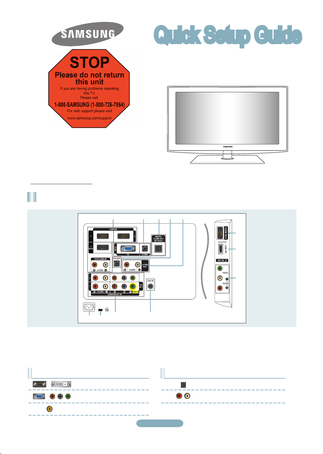
Rear Panel
this TV,
Please call;
For web support please visit
www.samsung.com/support
LN32B550/LN37B550/LN40B550/
LN46B550/ LN52B550
1 HDMI IN 1 (DVI), 2, 3, 4 /
DVI AUDIO IN [R-AUDIO-L]
2 PC IN [PC] / [AUDIO]
3 DIGITAL AUDIO OUT (OPTICAL)
4 EX-LINK
5 AUDIO OUT [R-AUDIO-L]
6 USB
7 AV IN 2
Video Input Performance Comparison
/
/
HDMI/DVI
PC/COMPONENT
VIDEO
Best
Better
Normal
8 ANT IN
9 COMPONENT IN 1, 2 / AV IN 1
0 KENSINGTON LOCK
! POWER INPUT
Audio Output Performance Comparison
English-1
OPTICAL (Digital)
AUDIO (Analog)
Best
Normal
Page 2
1
$
%
^
&
*
(
)
a
b
c
d
e
f
2
3
4
5
6
7
8
9
0
!
@
#
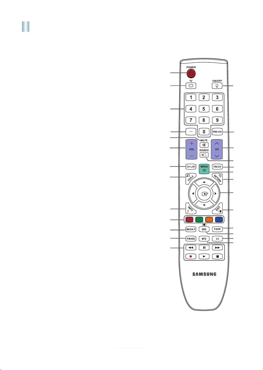
Remote Control
See “Remote Control” in the owner’s instructions for details.
1
POWER
Turns the TV on and off.
2
TV
Selects the TV mode directly.
3
NUMERIC BUTTONS
Press to change the channel.
4 _
Press to select additional
channels (digital and analog)
being broadcast by the same
station. For example, to select
channel '54-3', press '54', then
press '_' and '3'.
5
MUTE M
Press to temporarily cut off the
sound.
6
y
Press to increase or decrease
the volume.
7
CH LIST
Used to display Channel Lists
on the screen.
8
TOOLS
Use to quickly select frequently
used functions.
9
INFO
Press to display information on
the TV screen.
0
COLOR BUTTONS
Use these buttons in the
Channel list menus etc.
!
MEDIA.P
Allows you to play music files,
pictures, and movies.
@
P.MODE
Press to select the picture mode.
#
Use these buttons in the DMA
and Anynet+ modes. (∏:
This remote can be used to
control recording on Samsung
recorders with the Anynet+
feature)
$
ON/OFF
Pressing the ON/OFF @ light
button toggles between on and
off. When the remote control is
on, and a button is pressed on
the remote control, the remote
control buttons will be lit for a
moment. (Using the remote control with the ON/OFF @ light
button set to On will reduce the
battery usage time.)
%
PRE.CH
Enables you to return to the
previous channel you were
watching.
^ z
Press to change channels.
&
SOURCE
Press to display and select the
available video sources.
*
FAV.CH
Press to switch to your favorite
channels.
(
MENU
Displays the main on-screen
menu.
)
RETURN
Returns to the previous menu.
a
UP▲/DOWN▼/LEFT◄/
RIGHT►/
Use to select on-screen menu
items and change menu values.
b
EXIT
Press to exit the menu.
c
P.SIZE
Picture size selection.
d
SRS
Selects SRS TruSurround HD
mode.
e
CC
Controls the caption decoder.
f
MTS
Press to choose stereo, mono or
Separate Audio Program (SAP
broadcast).
@
ENTER
E
English-2
Page 3
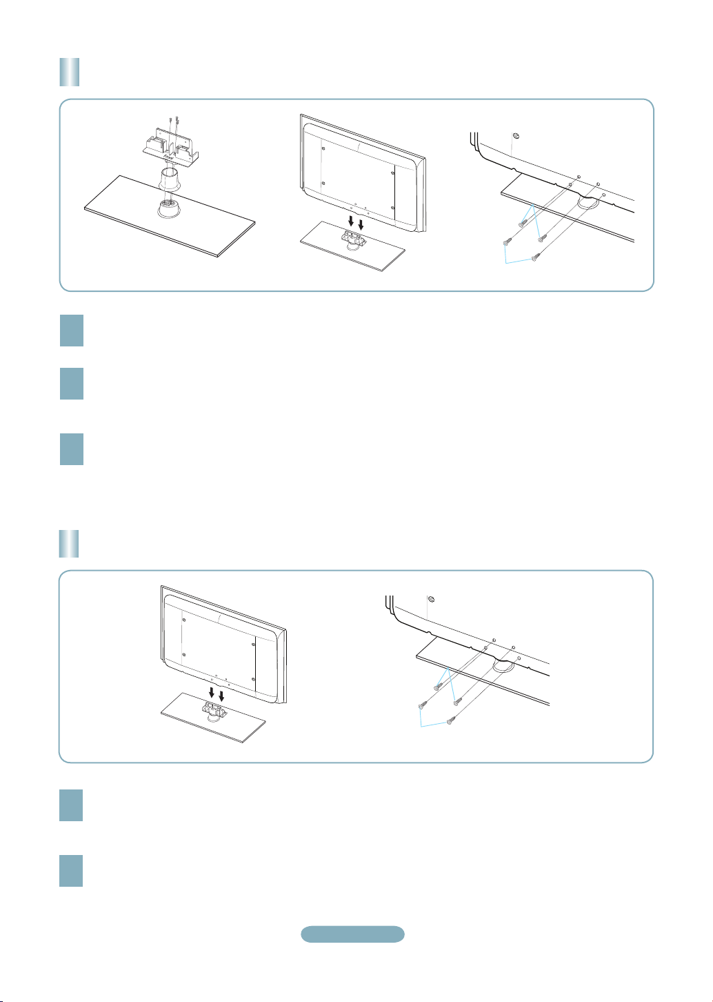
Installing the Stand
1
2
2
1
2
2
1
2
Back
Front
Place the Guide Stand and Cover Neck onto the stand and fasten it using the three screws.
(LN32B550)
1
Attach your LCD TV to the stand.
2
Two or more people should carry the TV.
➣
Make sure to distinguish between the front and back of the stand when attaching it.
➣
Fasten two screws at position 1 and then fasten two screws at position 2.
3
Installing the Stand
Attach your LCD TV to the stand.
1
Two or more people should carry the TV.
➣
Make sure to distinguish between the front and back of the stand when attaching it.
➣
Fasten two screws at position 1 and then fasten two screws at position 2.
(LN37B550, LN40B550, LN46B550, LN52B550)
2
English-3
Page 4

Connections
Connecting a DVD / Blu-ray player / Cable Box / Satellite receiver
(Set-Top Box) via HDMI
TV Rear Panel
DVD / Blu-ray player / Cable Box/
Satellite receiver (Set-Top Box)
or
HDMI Cable (Not supplied)
1
Each DVD / Blu-ray player / Cable Box / Satellite receiver (Set-Top Box) has a different back panel configuration.
➣
The TV may not output sound and pictures may be displayed with abnormal color when DVD / Blu-ray player / Cable Box / Satellite
➣
receiver (Set-Top Box) supporting HDMI versions older than 1.3 are connected. When connecting an older HDMI cable and there
is no sound, connect the HDMI cable to the HDMI IN 1 (DVI) jack and the audio cables to the DVI AUDIO IN [R-AUDIO-L] jacks
on the back of the TV. If this happens, contact the company that provided the DVD / Blu-ray player / Cable Box / Satellite receiver
(Set-Top Box) to confirm the HDMI version, then request an upgrade.
HDMI cables that are not 1.3 may cause annoying flicker or no screen display.
➣
or
TV Side Panel
Connect an HDMI Cable between
the HDMI IN 1 (DVI), 2, 3 or 4
1
jack on the TV and the HDMI
jack on the DVD / Blu-ray Player
or Cable Box / Satellite receiver
(Set-Top Box).
What is HDMI?
•
HDMI(High-Definition Multimedia
Interface), is an interface that enables the
transmission of digital audio and video
signals using a single cable.
•
The difference between HDMI and DVI
is that the HDMI device is smaller in
size and has the HDCP (High Bandwidth
Digital Copy Protection) coding feature
installed.
Connecting a DVD / Blu-ray player / Cable Box / Satellite receiver
(Set-Top Box) via DVI
Connect a DVI to HDMI Cable or DVIHDMI Adapter between the HDMI IN 1
1
(DVI) jack on the TV and the DVI jack on
the DVD / Blu-ray player / Cable Box /
Satellite receiver (Set-Top Box).
Connect Audio Cables between the DVI
AUDIO IN [R-AUDIO-L] jack on the TV
2
and the DVD / Blu-ray player / Cable Box /
Satellite receiver (Set-Top Box).
Each DVD / Blu-ray player / Cable Box /
➣
Satellite receiver (Set-Top Box) has a
different back panel configuration.
When connecting a DVD / Blu-ray
➣
player / Cable Box / Satellite receiver
(Set-Top Box), match the color of the
connection terminal to the cable.
When using an HDMI / DVI cable
➣
connection, you must use the HDMI IN
1 (DVI) jack.
DVD / Blu-ray player / Cable Box /
Satellite receiver (Set-Top Box)
TV Rear Panel
2
Audio Cable (Not supplied)
1
DVI to HDMI Cable (Not supplied)
English-4
Page 5
Connecting a DVD / Blu-ray player / Cable Box / Satellite receiver
(Set-Top Box) via Component cables
TV Rear Panel
Component Cable
1
(Not supplied)
Audio Cable (Not supplied)
2
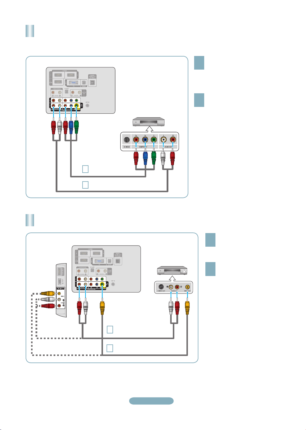
Connecting a VCR
DVD / Blu-ray player / Cable Box /
Satellite receiver (Set-Top Box)
Connect a Component Cable
between the COMPONENT IN (1 or
1
2) [Y, PB, PR] jacks on the TV and the
COMPONENT [Y, PB, PR] jacks on
the DVD / Blu-ray player / Cable Box /
Satellite receiver (Set-Top Box).
Connect Audio Cables between the
COMPONENT IN(1 or 2) [R-AUDIO-L]
2
jacks on the TV and the AUDIO OUT
jacks on the DVD / Blu-ray player / Cable
Box / Satellite receiver (Set-Top Box).
Component video separates the video
➣
into Y (Luminance (brightness)), Pb (Blue)
and Pr (Red) for enhanced video quality.
Be sure to match the component video
and audio connections. For example, if
connecting a Component video cable to
COMPONENT IN 1, connect the audio
cable to COMPONENT IN 1 also.
Each DVD / Blu-ray player / Cable Box /
➣
Satellite receiver (Set-Top Box) has a
different back panel configuration.
When connecting a DVD / Blu-ray player /
➣
Cable Box / Satellite receiver (Set-Top
Box), match the color of the connection
terminal to the cable.
TV Rear Panel
TV Side Panel
Audio Cable
2
(Not supplied)
Video Cable
1
(Not supplied)
When connecting a VCR, match the color of the connection terminal to the cable.
➣
When connecting to AV IN 1, the color of the AV IN 1 [Y/VIDEO] jack (Green) does not match the color of the video cable
➣
(Yellow).
English-5
VCR Rear Panel
Connect a Video Cable
between the AV IN 1 [Y/VIDEO]
1
or AV IN 2 [VIDEO] jack on the
TV and the VIDEO OUT jack
on the VCR.
Connect Audio Cables between
the AV IN (1 or 2) jacks on the
2
TV and the AUDIO OUT jacks on
the VCR.
If you have a ‘mono’ (non-stereo)
➣
VCR, use a Y-connector (not
supplied) to connect to the right
and left audio input jacks of the
TV. Alternatively, connect the
cable to the ‘R’ jack. If your VCR
is stereo, you must connect two
cables.
Each VCR has a different back
➣
panel configuration.
Page 6
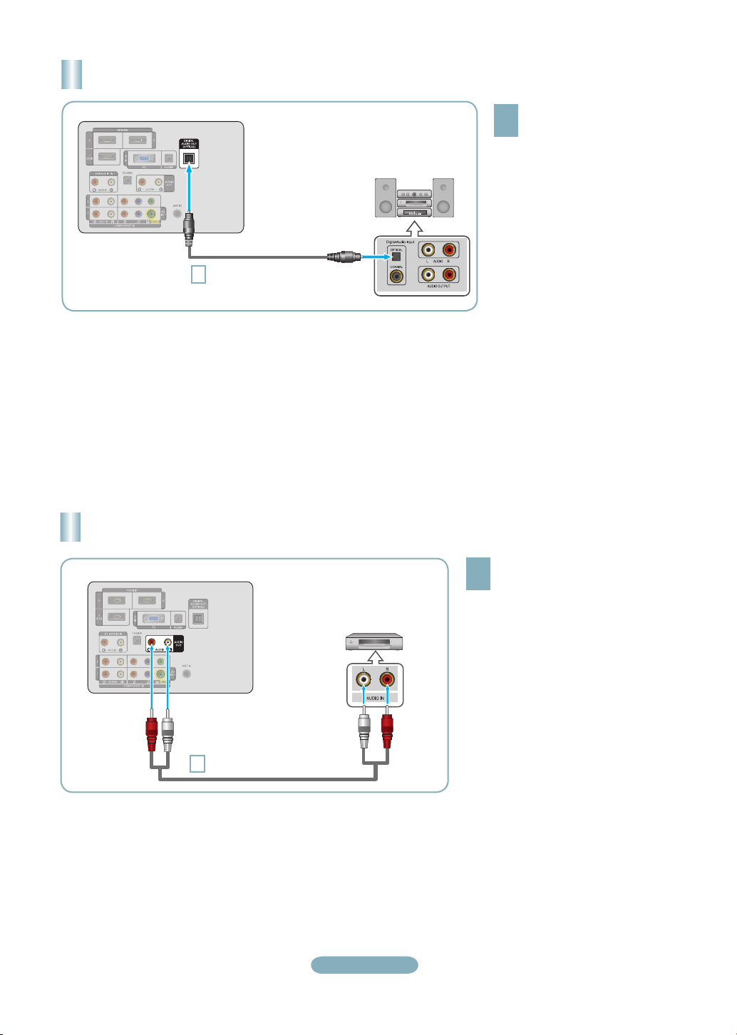
Connecting a Digital Audio System
TV Rear Panel
Digital Audio System
Optical Cable
1
(Not supplied)
When a Digital Audio System is connected to the DIGITAL AUDIO OUT (OPTICAL) jack: Decrease the volume of the TV and
➣
adjust the volume level with the system’s volume control.
5.1CH audio is possible when the TV is connected to an external device supporting 5.1CH.
➣
Each Digital Audio System has a different back panel configuration.
➣
When the Home Theater receiver is set to On, you can hear sound output from the TV’s Optical jack. When the TV is displaying
➣
a DTV(air) signal, the TV will send out 5.1 channel sound to the Home theater receiver. When the source is a digital component
such as a DVD / Blu-ray player / Cable Box / Satellite receiver (Set-Top Box) and is connected to the TV via HDMI, only 2
channel sound will be heard from the Home Theater receiver. If you want to hear 5.1 channel audio, connect the digital audio out
jack on DVD / Blu-ray player / Cable Box / Satellite receiver (Set-Top Box) directly to an Amplifier or Home Theater, not the TV.
Connect an Optical Cable
between the DIGITAL AUDIO
1
OUT (OPTICAL) jacks on the
TV and the Digital Audio Input
jacks on the Digital Audio
System.
Connecting an Amplifier / DVD Home Theater
TV Rear Panel
Audio Cable (Not supplied)
1
Amplifier/DVD Home Theater
Connect Audio Cables between the
AUDIO OUT [R-AUDIO-L] jacks on
1
the TV and Audio Input jacks on the
Amplifier / DVD Home Theater.
When an audio amplifier is connected
➣
to the AUDIO OUT [R-AUDIO-L]
jacks: Decrease the volume of the TV
and adjust the volume level with the
Amplifier’s volume control.
Each Amplifier/DVD Home Theater has
➣
a different back panel configuration.
When connecting an Amplifier/DVD
➣
Home Theater, match the color of the
connection terminal to the cable.
English-6
Page 7

Connecting a Camcorder
Using a Video Cable
TV Side Panel
Camcorder
Video Cable (Not supplied
1
Audio Cable (Not supplied)
2
Each Camcorder has a different back panel configuration.
➣
When connecting a Camcorder, match the color of the connection terminal to the cable.
➣
Using an HDMI Cable
TV Side Panel
HD Camcorder
HDMI Cable (Not supplied)
1
Connect a Video Cable between
the AV IN 2 [VIDEO] jack on the TV
1
and the VIDEO OUT jack on the
camcorder.
Connect Audio Cables between the
AV IN 2 [R-AUDIO-L] jacks on the
2
TV and the AUDIO OUT jacks on the
camcorder.
Connect an HDMI Cable between the
HDMI 4 jack on the TV and the HDMI
1
OUT jack on the camcorder.
English-7
Page 8
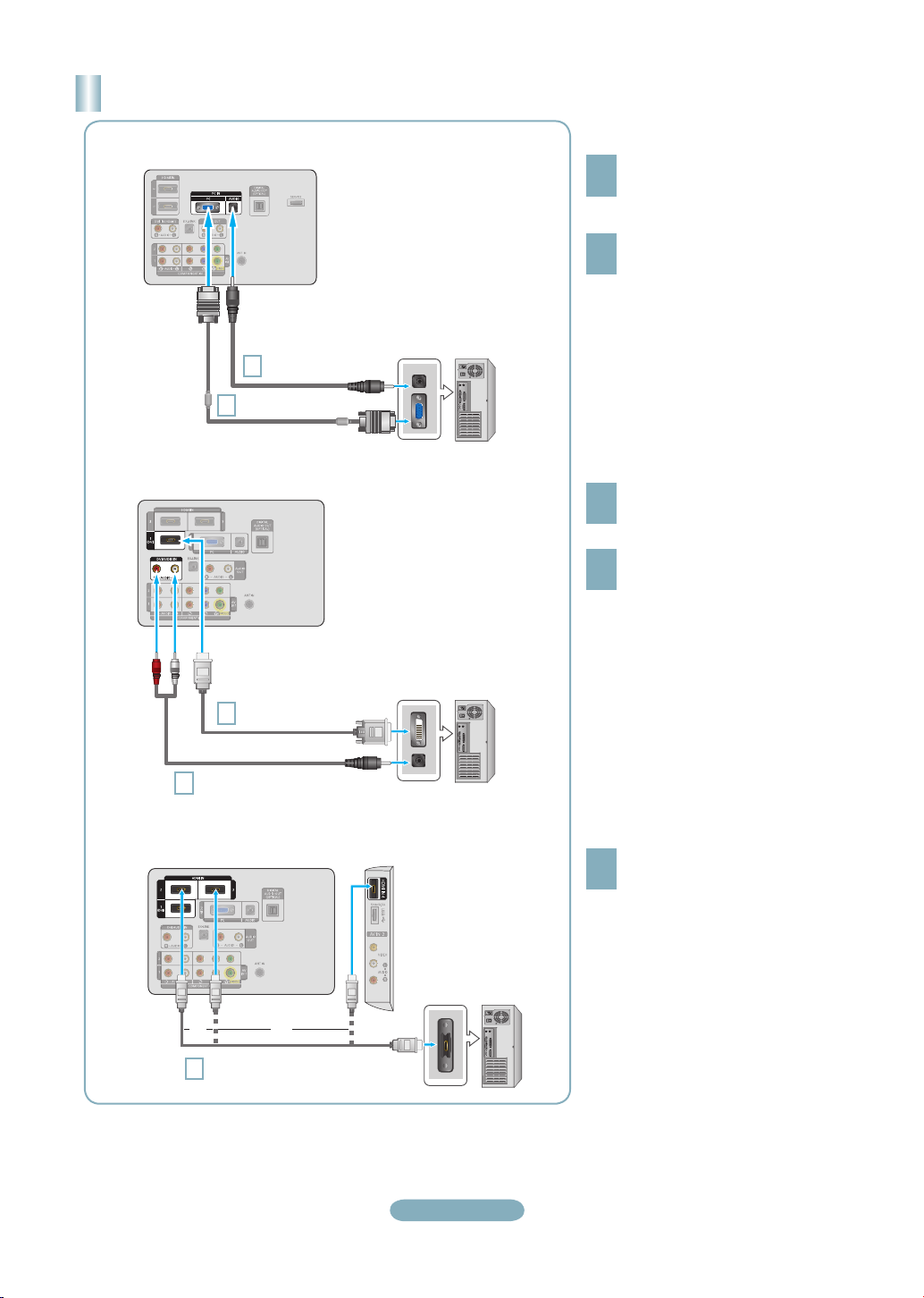
Connecting a PC
Using a D-Sub Cable
TV Rear Panel
PC Audio Cable
2
(Not supplied)
D-Sub Cable
(Not supplied)
1
PC
Using a D-Sub Cable
Connect a D-Sub Cable between
PC IN [PC] connector on the TV
1
and the PC output connector on
your computer.
Connect a PC Audio Cable
between the PC IN [AUDIO] jack
2
on the TV and the Audio Out jack of
the sound card on your computer.
When connecting a PC, match the
➣
color of the connection terminal to the
cable.
Using an HDMI/DVI Cable
TV Rear Panel
2
Using an HDMI Cable
TV Rear Panel
HDMI/DVI Cable
(Not supplied)
1
3.5 mm Stereo mini-plug/
2RCA Cable (Not supplied)
TV Side Panel
PC
Using an HDMI/DVI Cable
Connect an HDMI/DVI cable
between the HDMI IN 1 (DVI) jack
1
on the TV and the PC output jack
on your computer.
Connect a 3.5 mm Stereo miniplug
/ 2RCA Cable between the DVI
2
AUDIO IN [R-AUDIO-L] jack on the
TV and the Audio Out jack of the
sound card on your computer.
When using an HDMI/DVI cable
➣
connection, you must use the HDMI IN
1 (DVI) terminal.
Using an HDMI Cable
Connect an HDMI cable between
the HDMI IN 1 (DVI), 2, 3 or 4 jack
1
on the TV and the PC output jack on
your computer.
Each PC has a different back panel
➣
configuration.
oror
1
HDMI Cable (Not supplied)
PC
English-8
Page 9
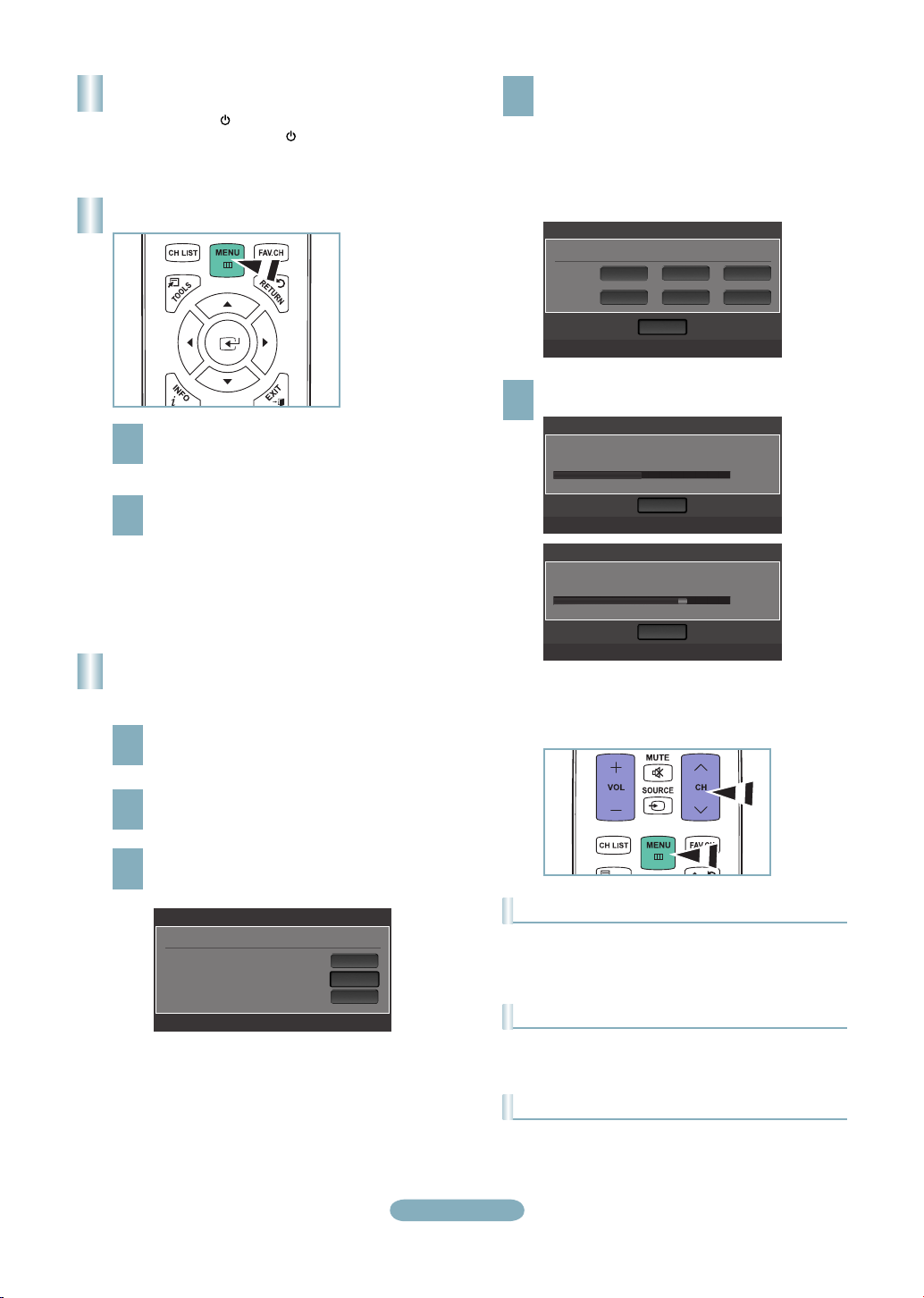
Turning the TV On and Off
Press the POWER button on the remote control.
You can also use the POWER button on the TV.
Viewing the Menus
With the power on, press the MENU button.
The main menu appears on the screen.
1
The menu’s left side has the following icons: Picture,
Sound, Channel, Setup, Input, Application, Support.
Press the ▲ or ▼ button to select one of the icons.
Then press the ENTERE button to access the
2
icon’s sub-menu. Press the EXIT button to exit.
The on-screen menus disappear from the
➣
screen after about one minute.
Storing Channels in Memory
(Automatic Method)
Press the MENU button to display the menu.
Press the ▲ or ▼ button to select “Channel”, then
1
press the ENTERE button.
When selecting the Cable TV system: Press the
ENTERE button to start the auto program.
4
Press the ▲,▼, ◄ or ► to select the correct analog
signal cable system source among “STD”, “HRC”,
and “IRC”. Press the ▲ or ▼ button to select “Start”,
then press the ENTERE button. If you have Digital
cable TV, select the cable system signal source for
both Analog and Digital.
Auto Program
Selects the cable system.
Analog
Digital
The TV begins memorizing all available stations.
Press the EXIT button to exit.
5
Auto Program in Progress.
DTV Cable : 12 Cable : 32
Removing scrambled channel.
DTV Cable : 16 Cable : 45
➣
STD
After all the available channels are stored, it
starts to remove scrambled channels. The Auto
program menu then reappears.
HRC IRC
HRC IRCSTD
Start
U Move E Enter m Skip
Auto Program
Stop
E Enter m Skip
Auto Program
DTV Cable 41
Stop
E Enter m Skip
Cable 38
50%
77%
Press the ▲ or ▼ button to select “Auto Program”,
then press the ENTERE button.
2
Press the ▲ or ▼ button to select the antenna
connection, then press the ENTERE button.
3
Auto Program
Select the Antenna source to memorize.
Air
Cable
Auto
U Move E Enter m Skip
Start
Start
Start
English-9
To Stop the Auto Program Function
Press the MENU button while the Auto Program function is
being executed. You can also press the ENTERE button
to stop the setup.
Checking to see if Channels were Stored in Memory
Press the CH button. Only the channels stored in memory
will be selected (in order).
Selecting the antennas
• Air: “Air” antenna signal.
• Cable: “Cable” antenna signal.
• Auto: “Air” and “Cable” antenna signals.
Page 10

Setting the Channel List
Changing the Picture Standard
You can delete or add a channel to display the channels
you want.
Press the MENU button. Press the ▲ or ▼ button to
select “Channel”, then press the ENTERE button.
1
Press the ▲ or ▼ button to select “Channel List”,
then press the ENTERE button.
Press the ◄ button to select “Added Channels”.
Press the ▲ or ▼ button to select “All Channels”.
2
Press the ENTERE button.
Press the ▲ or ▼ button to select a channel to
delete, then press the TOOLS button. Press the
3
ENTERE button to select “Delete”.
Press the ▲ or ▼ button to select a channel to add,
then press the TOOLS button. Press the ENTERE
4
button and the channel is added.
All Channels
2 Air
4 Air
4-2 ♥ TV #8
8 Air
13 Air
13-1 ♥ TV #3
Air
Zoom Select T Tools
Delete
Add to Favorite
Timer Viewing
Channel Name Edit
Select All
Alice’s Adventures in Wonderland
Auto Program
Setting Your Favorite Channels
You can set channels you watch frequently as favorites.
Press the MENU button. Press the ▲ or ▼ button to
select “Channel”, then press the ENTERE button.
1
Press the ▲ or ▼ button to select “Channel List”,
then press the ENTERE button.
Press the ◄ button to select “Added Channels”.
Press the ▲ or ▼ button to select “All Channels”.
2
Press the ENTERE button.
Press the ▲ or ▼ button to select a channel as a
favorite channel. Press the TOOLS button.
3
You can select the type of picture which best corresponds
to your viewing requirements.
Press the MENU button to display the menu.
Press the ENTERE button, to select “Picture”.
1
Press the ENTERE button to select “Mode”.
Press the ▲ or ▼ button to select “Dynamic”,
2
“Standard” or “Movie”.
Press the ENTERE button.
Picture
Mode
:
Backlight : 7
Contrast : 95
Brightness : 45
Sharpness : 50
Color : 50
Tint (G/R) : G50/R50
Standard
Dynamic
Standard
Movie
►
Picture Mode
• Dynamic: Selects the picture for high-definition in a bright
room.
•
Standard: Selects the picture for the optimum display in a
normal environment.
•
Movie: Selects the picture for viewing movies in a dark
room.
Press the ▲ or ▼ button to select “Add to Favorite”,
then press the ENTERE button. The “♥” symbol
4
will be displayed and the channel will be set as a
favorite.
The "♥" symbol will be displayed and the
➣
channel will be set as a favorite.
All favorite channels will be shown in the
➣
"Favorite" menu.
All Channels
2 Air
4 Air
4-2 ♥ TV #8
8 Air
13 Air
13-1 ♥ TV #3
Air
Zoom Select T Tools
Delete
Add to Favorite
Timer Viewing
Channel Name Edit
Select All
Alice’s Adventures in Wonderland
Auto Program
English-10
Page 11

Customizing the Picture Settings
Setting the Screen Size
Your television has several setting options that allow you to
control the picture quality.
To select the desired picture mode, follow the
“Changing the Picture Standard” instructions
1
numbers 1 and 2.
Press the ▲ or ▼ button to select “Backlight”,
“Contrast”, “Brightness”, “Sharpness”, “Color” or
2
“Tint(G/R)”, then press the ENTERE button.
Press the ◄ or ► button to decrease or increase
the value of a particular item. Press the EXIT button
3
to exit.
When you make changes to “Backlight”,
➣
“Contrast”, “Brightness”, “Sharpness”, “Color”
or “Tint(G/R)”, the OSD will be adjusted
accordingly.
In PC mode, you can only make changes to
➣
“Backlight”, “Contrast” and “Brightness”.
Settings can be adjusted and stored for each
➣
external device you have connected to an input
of the TV.
The energy consumed during use can be
➣
significantly reduced if the brightness level of
the picture is lowered, which will reduce the
overall running cost.
Mode : Standard
Picture
Backlight : 8
Contrast : 95
Brightness : 45
Sharpness : 50
Color : 50
Tint (G/R) : G50/R50
Advanced Settings
►
Occasionally, you may want to change the size of the
image on your screen. Your TV comes with six screen size
options, each designed to work best with specific types of
video input. Your cable box or satellite receiver may have
its own set of screen sizes as well. In general, though, you
should view the TV in 16:9 mode as much as possible.
To select the desired picture mode, follow the
“Changing the Picture Standard” instructions
1
number 1.
Press the ▲ or ▼ button to select “Picture Options”,
then press the ENTERE button. Press the ▲ or
2
▼ button to select “Size”, then press the ENTERE
button.
Press the ▲ or ▼ button to select the screen format
you want. Press the ENTERE button.
3
Press the EXIT button to exit.
• 16:9
: Sets the picture to 16:9 wide mode.
• Zoom1: Magnifies the size of the picture on the screen.
• Zoom2
: Magnifies the size of the picture more than
“Zoom1”.
•
Wide Fit: Enlarges the aspect ratio of the picture to fit the
entire screen.
• 4:3: Sets the picture to 4:3 normal mode.
•
Screen Fit: Use the function to see the full image without
any cutoff when HDMI (720p/1080i/1080p), Component
(1080i/1080p) or DTV (1080i) signals are input.
8Backlight
AdjustMove
Enter Return
Picture Adjustment
• Backlight: Adjusts the brightness of LCD back light.
•
Contrast: Adjusts the contrast level of the picture.
•
Brightness: Adjusts the brightness level of the picture.
•
Sharpness: Adjusts the edge definition of the picture.
•
Color: Adjusts color saturation of the picture.
•
Tint(G/R): Adjusts the color tint of the picture.
English-11
Page 12

To Select the Source
TV
AV1 ---AV2 ---Component1 ---Component2 ---PC ----
Refresh
T
Tools
Press the SOURCE button on the Remote Control
You can select the TV mode or an input source connected to the TV set. Use this button to choose an input source that you
would like to watch.
➣
Available signal sources: TV, AV1, AV2, Component1, Component2, PC, HDMI1/DVI, HDMI2, HDMI3. (LN52B550)
TV, AV, Component, PC, HDMI1/DVI, HDMI2, HDMI3. (LN32B550, LN37B550, LN40B550, LN46B550)
➣
You can choose only those external devices that are connected to the TV. In the “Source List”, connected inputs will be
highlighted and sorted to the top. Inputs that are not connected will be sorted to the bottom.
➣
Using the Color buttons on the remote with the Source list
• Red (Refresh): Refreshes the connected external devices. Press this if your Source is on and connected, but does not
appear in the list.
• TOOLS (Tools): Displays the “Edit Name” and “Information” menus.
English-12
Page 13

Troubleshooting
If the TV seems to have a problem, first try this list of possible problems and solutions.
If none of these troubleshooting tips apply, call Samsung customer service at 1-800-SAMSUNG. (726-7864)
Problem Possible Solution
Poor picture Try another channel. / Adjust the antenna. / Check all wire connections.
Poor sound quality. Try another channel. / Adjust the antenna.
No picture or sound. Try another channel. / Press the SOURCE button. /
No sound or sound is too low at maximum
volume.
Picture rolls vertically. Check all wire connections.
There is a problem with the picture Run the Picture test in the Self diagnostic menu.
There is a problem with the sound Run the Sound test in the Self diagnostic menu.
The TV operates erratically. Unplug the TV for 30 seconds, then try operating it again.
The TV won’t turn on. Make sure the wall outlet is working.
Remote control malfunctions Replace the remote control batteries.
'Check signal cable' message. Ensure that the signal cable is rmly connected to the PC source.
'Not Supported Mode' message. Check the maximum resolution and connected device’s Video frequency.
Digital broadcasting screen problem. Please check the digital signal strength and input antenna.
The image is too light or too dark. Adjust the Brightness and Contrast. / Adjust the Fine tuning.
Black bars on the screen. Make sure the broadcast you’re receiving is High Denition (HD).
Picture has a Red/Green or Pink tint. Make sure the Component cables are connected to the correct jacks.
Closed Captioning not working. If you are using a Cable/Satellite box, you must set Closed Captioning on the box,
Snowy picture. Your cable box may need a rmware upgrade. Please contact your Cable
Ghosting on picture This is sometimes caused by compatibility issues with your cable box.
Horizontal bars appear to icker, jitter or
shimmer on the image.
Vertical bars appear to icker, jitter or
shimmer on the image.
Screen is black and power indicator light
blinks steadily.
Image is not centered on the screen. Adjust the horizontal and vertical position.
The picture appears distorted in the
corner of the screen.
The 'Resets all settings to the default
values' message appears.
Make sure the TV is plugged in. / Check the antenna connections.
First, check the volume of units connected to your TV (digital broadcasting
receiver, DVD, cable broadcasting receiver, VCR, etc.). Then, adjust the TV
volume accordingly.
Clean the upper edge of the remote control (transmission window).
Check the battery terminals.
Compare these values with the data in the Display Modes.
HD channels sometimes broadcast Standard Denition (SD) programming, which
can cause black bars.
Set your cable/satellite box to stretch or widescreen mode to eliminate the bars.
not your TV.
company.
Try connecting Component cables instead.
Adjust the Coarse tuning and then adjust the Fine tuning.
Adjust the Coarse tuning and then adjust the Fine tuning.
On your computer check: Power, Signal Cable.
The TV is using its power management system.
Move the computer's mouse or press any key on the keyboard.
The screen position must be adjusted on the output source (i.e. STB) with a
digital signal.
If "Just Scan" is selected with some external devices, the picture may appear
distorted in the corner of the screen. This symptom is caused by the external
devices, not TV.
This appears when you press and hold the EXIT button for a while. The product
settings are reset to the factory defaults.
English-13
Page 14

1
!
0
8
9
1
6
7
2 3 4 5
Guide d'installation rapide
STOP
Veuillez SVP ne pas
LN32B550/LN37B550/LN40B550/
LN46B550/ LN52B550
retourner cet appareil.
En cas de problèmes de fonctionnement,
veuillez composer le numéro suivant :
1-800-SAMSUNG (1-800-726-7864)
Pour obtenir de l’assistance en ligne,
allez au lien suivant :
www.samsung.com/support
1-800-SAMSUNG (7267864)
Samsung Electronics America, Inc.
105 Challenger Road Ridgefield Park, NJ 07660-0511
Samsung Electronics Canada Inc., Customer Service
55 Standish Court Mississauga, Ontario L5R 4B2
Centre d’appel – heures de service (du lundi au dimanche, de 9 h à 12 h (HNE)
Pour enregistrer ce produit, veuillez SVP aller à :
www.samsung.com/register
Panneau arrière
1 HDMI IN 1 (DVI), 2, 3, 4 /
DVI AUDIO IN [R-AUDIO-L]
2 PC IN [PC] / [AUDIO]
3 DIGITAL AUDIO OUT (OPTICAL)
4 EX-LINK
5 AUDIO OUT [R-AUDIO-L]
6 USB
7 AV IN 2
Entrée vidéo – tableau comparatif des performances
/
/
HDMI/DVI
PC/COMPONENT
VIDEO
La meilleure
Excellente
Normale
Sortie audio – tableau comparatif des performances
Français-1
8 ANT IN
9 COMPONENT IN 1, 2 / AV IN 1
0 VERROU KENSINGTON
! PUISSANCE CONSOMMÉE
OPTICAL (Digital)
AUDIO (Analog)
La meilleure
Normale
Page 15

1
$
%
^
&
*
(
)
a
b
c
d
e
f
2
3
4
5
6
7
8
9
0
!
@
#
Télécommande
Reportez-vous à la section "Télécommande" du guide de l’utilisateur pour plus de détails.
1
POWER : Permet d’allumer et
d’éteindre le téléviseur.
2
TV: Permet de sélectionner
directement le mode TV.
3
TOUCHES NUMÉRIQUES :
Appuyer sur cette touche pour
changer de canal.
4
_ : Appuyer sur cette touche
pour sélectionner des canaux
supplémentaires (numériques)
diffusées par la même station.
Par exemple, pour sélectionner
le canal ‘54-3’, appuyez sur
‘54’, puis sur _ et ‘3’.
5
MUTE M : Appuyer sur cette
touche pour couper le son
temporairement.
6 y
touche pour augmenter ou
baisser le volume.
7
CH LIST : Sert à afcher la liste
des canaux à l'écran.
8
TOOLS : Sert à sélectionner
rapidement les fonctions
fréquemment utilisées.
9
INFO : Appuyer sur cette
touche pour afcher de
l'information à l'écran.
0
TOUCHES DE COULEUR :
Utiliser ces touches dans les
menus de liste de canaux, etc.
!
MEDIA.P: Appuyez sur cette
touche pour lire des chiers
musicaux, des images et des
lms.
@
P.MODE: Appuyer sur cette
touche pour sélectionner le
mode d'image.
#
Ces touches fonctionnent dans
les modes DMA et Anynet+.
(∏ : Cette télécommande
peut servir à commander
l’enregistrement sur des
enregistreurs Samsung avec la
fonction Anynet+).
: Appuyer sur cette
$
ON/OFF @: Appuyez sur la
touche ON/OFF @ pour activer
et désactiver le rétroéclairage.
Lorsque la télécommande est
activée et que vous appuyez
sur une de ses touches, ces
dernières sont rétroéclairées
pendant un moment. (L’utilisation
de la télécommande lorsque la
touche de rétroéclairage ON/OFF
@
est réglée à On réduit la
durée de vie des piles.)
%
PRE-CH: Permet de revenir au
canal écouté précédemment.
^ z
touche pour changer de canal.
&
SOURCE: Appuyer sur
cette touche pour afcher et
sélectionner les sources vidéo
disponibles.
*
FAV.CH: Appuyer sur cette
touche pour naviguer entre vos
canaux favoris.
(
MENU: Afche le menu à l’écran
principal.
)
RETURN: Permet de retourner au
menu précédent.
a
HAUT▲/BAS▼/GAUCHE◄/
DROIT►/ENTERE: Sert à
sélectionner des articles de
menus afchés et à modier les
valeurs des menus.
b
EXIT: Appuyer sur cette touche
pour sortir du menu.
c
P.SIZE: Permet de sélectionner le
format de l'image.
d
SRS: Permet de sélectionner
le mode SRS TruSurround HD
mode.
e
CC: Permet de commander la
fonction de sous-titrage.
f
MTS: Appuyer sur cette touche
pour sélectionner le mode stéréo,
mono ou SAP (Separate Audio
Program).
: Appuyer sur cette
Français-2
Page 16

Installation du support
1
2
2
1
2
2
1
2
Arrière
Avant
Placez le guide de support et le collet sur le support et fixez-les à l’aide des vis.
(LN32B550)
1
Fixez votre téléviseur ACL sur le support.
2
Deux personnes ou plus devraient porter le téléviseur.
➣
S’assurer de bien distinguer le devant et l’arrière du support lors de l’assemblage.
➣
Vissez les vis à la position 1, puis vissez les vis à la position 2.
3
Installation du support
Fixez votre téléviseur ACL sur le support.
1
Deux personnes ou plus devraient porter le téléviseur.
➣
S’assurer de bien distinguer le devant et l’arrière du support lors de l’assemblage.
➣
Vissez les vis à la position 1, puis vissez les vis à la position 2.
(LN37B550, LN40B550, LN46B550, LN52B550)
2
Français-3
Page 17

Conexions
Branchement d’un lecteur DVD/Blu-ray/câblosélecteur ou récepteur satellite
(boîtier décodeur) via HDMI
Panneau arrière du téléviseur
Panneau arrière d’un lecteur DVD/
Blu-ray/câblosélecteur ou récepteur
satellite (boîtier décodeur)
ou
Câble HDMI (non fourni)
1
Le téléviseur peut n’émettre aucun son et les couleurs des images s’afficher anormalement lorsqu’un lecteur DVD/Blu-ray/
➣
câblosélecteur ou récepteur satellite (boîtier décodeur) comporte une version HDMI antérieure à 1.3. Lorsque vous branchez un câble
HDMI doté d’une version antérieure et qu’aucun son n’est émis, branchez le câble HDMI à la prise HDMI IN 1 (DVI) et les câbles audio
aux prises DVI AUDIO IN (HDMI1) [R-AUDIO-L] situées à l’arrière du téléviseur. Le cas échéant, communiquez avec le fournisseur du
lecteur DVD/Blu-ray/câblosélecteur ou récepteur satellite afin de confirmer la version HDMI et demander une mise à niveau.
Les câbles HDMI autres que ceux de version 1.3 peuvent provoquer un papillotement ou une absence d'image.
➣
ou
Panneau latéral
du téléviseur
Branchez un câble HDMI entre
la prise HDMI IN 1 (DVI), 2, 3
1
ou 4) du téléviseur et la prise
HDMI du lecteur DVD/Bluray/câblosélecteur ou récepteur
satellite (boîtier décodeur).
Qu'est-ce que le mode HDMI?
•
HDMI ou (interface multimédia
haute définition) est une interface de
transmission de signaux numériques
audio et vidéo par un seul câble.
•
La distinction entre les interfaces HDMI
et DVI réside dans le fait qu'un apapreil
HDMI est plus petit et qu'il est doté du
composant de codage HDCP (protection
contre la copie numérique à large bande
passante).
La configuration du panneau arrière
➣
de chaque lecteur DVD/Blu-ray/
câblosélecteur ou récepteur satellite
(boîtier décodeur) diffère.
Branchement d’un lecteur DVD/Blu-ray/câblosélecteur ou récepteur satellite
(boîtier décodeur) via DVI
Branchez un câble DVI vers HDMI ou
un adaptateur DVI-HDMI entre la prise
1
HDMI IN 1 (DVI) du téléviseur et la
prise DVI du lecteur DVD/Blu-ray/du
câblosélecteur ou du récepteur satellite
(boîtier décodeur).
Branchez les câbles audio entre la prise
DVI AUDIO IN [R-AUDIO-L] du téléviseur
2
et le lecteur DVD/Blu-ray/le câblosélecteur
ou le récepteur satellite (boîtier décodeur).
La configuration du panneau arrière
➣
de chaque lecteur DVD/Blu-ray/
câblosélecteur ou récepteur satellite
(boîtier décodeur) diffère.
Lorsque vous branchez un lecteur
➣
DVD/Blu-ray/câblosélecteur ou
récepteur satellite (boîtier décodeur),
assurez-vous que la couleur de la prise
correspond à celle du câble.
Utilisez la prise d’entrée HDMI IN 1
➣
(DVI) dans le cas d’un branchement
HDMI/DVI.
Lecteur DVD/Blu-ray/câblosélecteur ou
récepteur satellite (boîtier décodeur)
Panneau arrière du téléviseur
2
Câble audio (non fourni)
1
Câble DVI vers HDMI (non fourni)
Français-4
Page 18

Branchement d’un lecteur DVD/Blu-ray/câblosélecteur ou récepteur
satellite (boîtier décodeur) via les câbles de composantes
Panneau arrière du téléviseur
Câble de composante
1
(non fourni)
Câble audio (non fourni)
2
Lecteur DVD/Blu-ray/
câblosélecteur ou récepteur
satellite (boîtier décodeur)
Branchez un câble composant entre
les prises COMPONENT IN (1 ou
1
2) [Y, PB, PR] du téléviseur et les
prises COMPONENT [Y, PB, PR] du
lecteur DVD/Blu-ray/câblosélecteur ou
récepteur satellite (boîtier décodeur).
Branchez les câbles audio entre les
prises COMPONENT IN(1 ou 2) [R-
2
AUDIO-L] du téléviseur et les prises
AUDIO OUT du lecteur DVD/Blu-ray/
câblosélecteur ou récepteur satellite
(boîtier décodeur).
La composante vidéo décompose le signal selon
➣
les caractéristiques Y (Luminosité), Pb (Bleu)
et Pr (Rouge) afin d'améliorer l'image. Assurezvous de faire correspondre la composante
vidéo et les connexions audio. Par exemple,
si un câble vidéo composante est branché à
COMPONENT IN 1, le câble audio doit être
branché à COMPONENT IN 1 également.
La configuration du panneau arrière de
➣
chaque lecteur DVD/Blu-ray/câblosélecteur
ou récepteur satellite (boîtier décodeur)
diffère.
Lorsque vous branchez un lecteur
➣
DVD/Blu-ray/câblosélecteur ou récepteur
satellite (boîtier décodeur), assurez-vous
que la couleur de la prise correspond à
celle du câble.
Connexion d'un magnétoscope
Panneau arrière du téléviseur
Panneau latéral
du téléviseur
2
Câble audio (non fourni)
1
Câble vidéo (non fourni)
Lorsque vous branchez magnétoscope, assurez-vous que la couleur de la prise correspond à celle du câble.
➣
Dans le cas de la connexion à AV IN 1, la couleur de la prise AV IN 1 [Y/VIDEO] (vert) ne correspond pas à la couleur du
➣
câble vidéo (jaune).
Panneau arrière du
Français-5
magnétoscope
Branchez un câble vidéo entre
la prise AV IN 1 [Y/VIDEO] ou
1
AV IN 2 [VIDEO] du téléviseur
et la prise VDEO OUT du
magnétoscope.
Branchez les câbles audio entre
les prises AV IN (1 ou 2) du
2
téléviseur et les prises AUDIO
OUT du magnétoscope.
Si le magnétoscope est de type
➣
‘mono’ (non stéréo), il faut utiliser
un connecteur en Y (non fourni)
pour effectuer les connexions
aux prises d'entrée audio droite
et gauche du téléviseur. l est
également possible de brancher
le câble à la prise ‘R’. Si le
magnétoscope est de type ‘stéréo’,
il faut brancher deux câbles.
Chaque magnétoscope possède
➣
une configuration de panneau
arrière différente.
Page 19

Connexion d'une chaîne audio numérique
Panneau arrière du téléviseur
Chaîne audio numérique
1
Câble optique (non fourni)
Lorsqu'une chaîne audionumérique est branchée à la prise DIGITAL AUDIO OUT (OPTICAL) : baissez le volume du téléviseur,
➣
puis réglez le volume à l'aide de la commande de volume de la chaîne.
La diffusion audio à 5.1 canaux est possible lorsque le téléviseur est raccordé à un appareil externe doté de cette fonction audio.
➣
La configuration du panneau arrière de chaque système audio numérique diffère.
➣
Lorsque le récepteur de la chaîne de cinéma maison est réglé à On, vous pouvez entendre le son provenant de la prise optique
➣
du téléviseur. Lorsque le téléviseur émet des signaux numériques (air), il transmet le son en 5.1 canaux au récepteur de la
chaîne de cinéma maison. Lorsque la source est un composant numérique, comme un lecteur DVD/Blu-ray/câblosélecteur ou
récepteur satellite (boîtier décodeur), et que ce dernier est branché au téléviseur par un câble HDMI, le récepteur de la chaîne de
cinéma maison ne fera entendre qu’un son à deux canaux. Si vous désirez entendre un son à 5.1 canaux, branchez directement
la prise de sortie audionumérique du lecteur DVD/Blu-ray/câblosélecteur ou récepteur satellite (boîtier décodeur) à l’amplificateur
ou à la chaîne de cinéma maison, plutôt qu’au téléviseur.
Branchez un câble optique
entre les prises DIGITAL
1
AUDIO OUT (OPTICAL)
du téléviseur et les prises
d'entrée audio numérique de
la chaîne.
Connexion d'un amplificateur/lecteur DVD de cinéma maison
Panneau arrière du téléviseur
Câble audio (non fourni)
1
Amplificateur/
lecteur DVD de cinéma maison
Branchez un câble audio entre les
prises AUDIO OUT [R-AUDIO-L] du
1
téléviseur et les prises d'entrée audio
de l'amplificateur/ lecteur DVD de
cinéma maison.
Lorsqu'un amplificateur audio
➣
est branché aux prises de sortie
gauche et droite AUDIO OUT [RAUDIO-L] : Baissez le volume du
téléviseur et réglez le volume à
l’aide de la commande de volume de
l’amplificateur.
La configuration du panneau arrière de
➣
chaque amplificateur/lecteur DVD de
cinéma maison diffère.
Lorsque vous connectez un
➣
amplificateur/lecteur DVD de cinéma
maison, assurez-vous que la couleur
de la prise correspond à celle du câble.
Français-6
Page 20

Connexion d'un caméscope
Utilisation d’un câble vidéo
Panneau latéral
du téléviseur
Caméscope
Câble vidéo (non fourni)
1
Câble audio (non fourni)
2
La configuration arrière de chaque caméscope est différente suivant les appareils.
➣
Lorsque vous branchez un caméscope, assurez-vous que la couleur de la prise correspond à celle du câble.
➣
Branchez un câble vidéo entre la
prise AV IN 2 [VIDEO] du téléviseur
1
et la prise VDEO OUT du caméscope.
Branchez les câbles audio entre
les prises AV IN 2 [R-AUDIO-L] du
2
téléviseur et les prises AUDIO OUT
du caméscope.
Utilisation d’un câble HDMI
Caméscope HD
Panneau latéral
du téléviseur
Branchez un câble HDMI entre la
prise HDMI 4 du téléviseur et la prise
1
HDMI OUT du caméscope.
Câble HDMI (non fourni)
1
Français-7
Page 21

Connexion d'un PC
Utilisation d’un câble secondaire D
Panneau arrière du téléviseur
Câble audio de PC
2
(non fourni)
Câble secondaire D
(non fourni
1
PC
Utilisation d’un câble secondaire D
Branchez un câble secondaire D
entre le connecteur PC IN [PC] du
1
téléviseur et le connecteur de sortie
PC de votre ordinateur.
Branchez un câble audio PC
entre la prise PC IN [AUDIO] du
2
téléviseur et la prise de sortie audio
de la carte son de l'ordinateur.
Lorsque vous connectez un PC,
➣
assurez-vous que la couleur de la
prise correspond à celle du câble.
Utilisation d’un câble HDMI/DVI
Panneau arrière du téléviseur
1
Câble mini-prise stéréo
2
3,5 mm/2RCA (non fourni)
Utilisation d’un câble HDMI
Panneau arrière du téléviseur
Câble HDMI/DVI
(non fourni)
Panneau latéral
du téléviseur
PC
Utilisation d’un câble HDMI/DVI
Connectez un câble HDMI/DVI
entre la prise HDMI IN 1 (DVI) du
1
téléviseur et la prise de sortie PC
de l'ordinateur.
Branchez un câble mini-prise
stéréo 3,5 mm/2RCA entre la prise
2
DVI AUDIO IN [R-AUDIO-L] du
téléviseur et la prise de sortie audio
de la carte son de l’ordinateur.
Il faut utiliser la borne d’entrée HDMI IN
➣
1 (DVI) dans le cas d’un branchement
à l’aide d’un câble HDMI/DVI.
Utilisation d’un câble HDMI
Connectez un câble HDMI entre la
prise HDMI IN 1 (DVI), 2, 3 ou 4 du
1
téléviseur et la prise de sortie PC de
l'ordinateur.
La configuration du panneau arrière
➣
de chaque PC diffère.
1
Câble HDMI (non fourni)
PC
ouou
Français-8
Page 22

Mise en marche et arrêt de la télévision
Appuyez sur le bouton POWERP de la télécommande.
Il est aussi possible d’utiliser la touche POWERP du
téléviseur.
Visualisation des menus
Une fois l’appareil allumé, appuyez sur le bouton
MENU. Le menu principal apparaît à l’écran.
1
La partie gauche du menu comprend les icônes
suivantes : Image, Son, Chaîne, Configuration,
Entrée, Support technique.
Appuyer sur la touche ▲ ou ▼ pour sélectionner
une des icônes. Puis appuyez sur ENTERE pour
2
accéder au sous-menu de l’icône. Appuyez sur le
bouton EXIT pour quitter.
Les menus affichés à l’écran disparaissent
➣
après une minute environ.
Enregistrement des canal dans la
mémoire (méthode automatique)
Appuyez sur le bouton MENU pour afficher le menu.
Appuyez sur les bouton ▲ ou ▼ pour sélectionner
1
“Chaîne”, puis appuyez sur le bouton ENTERE.
Au moment de la sélection du système de télévision
par Câble : Appuyez sur ENTERE pour amorcer la
4
mémorisation automatique.
Appuyer sur les touches ▲,▼, ◄ ou ► pour choisir
la source du signal analogique appropriée “STD”,
“HRC”, ou “IRC”. Appuyer sur la touche ▲ ou ▼
pour sélectionner “Démarrer”, puis sur ENTERE.
Si le Câble est numérique, sélectionner la source de
signal pour une diffusion analogique et numérique.
Prog. auto
Choisir le tableau de câblodiffusion.
Analogique
Numérique
Le téléviseur commence alors à mémoriser tous les
canaux disponibles. Appuyez sur le bouton EXIT
5
pour quitter.
Progr. Aut. en cours
DTV Câble : 12 Câble : 32
Removing scrambled channel.
DTV Câble : 16 Câble : 45
➣
STD
Une fois tous les canaux mémorisés, le
téléviseur commence à éliminer les canaux
brouillés. Puis le menu Prog. auto s’affiche.
HRC IRC
HRC IRCSTD
Démarrer
U Dépl. E Intro. m Passer
Prog. auto
Stop
E Enter m Skip
Prog. auto
DTV Câble 41
Stop
E Enter m Skip
Câble 38
50%
77%
Appuyez sur les bouton ▲ ou ▼ pour sélectionner
“Prog. auto”, puis appuyez sur le bouton ENTERE.
2
Utilisez les bouton ▲ ou ▼ pour sélectionner
l’antenne souhaitée, puis appuyez sur le bouton
3
ENTERE.
Prog. auto
Mémoriser une source d'antenne.
Air
Câble
Auto
U Dépl. E Intro. m Passer
Démarrer
Démarrer
Démarrer
Français-9
Pour arrêter la fonction de programmation automatique
Appuyez sur la touche MENU pendant que la fonction de
programmation automatique est en cours d’exécution. Vous
pouvez également appuyer sur ENTERE pour interrompre
la configuration.
Pour vérifier si les canaux ont été mémorisés
Appuyez sur la touche CH. Seuls les canaux mémorisés
seront sélectionnés (dans l’ordre).
Sélection du mode de réception
• Air : Signal d'antenne de type “Air”.
• Câble : signal d'antenne de type “Câble”.
• Auto : Signaux d'antenne de type “Air” et “Câble”.
Page 23

Réglage de la liste de canaux
Changement du format normal de l’image
Il est possible d’ajouter ou de supprimer un canal pour
afficher seulement les canaux désirés.
Appuyez sur le bouton MENU. Appuyez sur les
bouton ▲ ou ▼ pour sélectionner “Chaîne”, puis
1
appuyez sur le bouton ENTERE. Appuyez sur
les bouton ▲ ou ▼ pour sélectionner “Liste des
canaux”, puis appuyez sur le bouton ENTERE.
Appuyer sur la touche ◄ pour sélectionner “Canaux
ajoutés”. Appuyer sur la touche ▲ ou ▼ pour choisir
2
“Tous les canaux”. Appuyer sur la touche ENTERE.
Appuyer sur la touche ▲ ou ▼ pour sélectionner un
canal à supprimer, puis sur la touche TOOLS. Appuyer
3
sur la touche ENTERE pour choisir “Supprimer”.
Appuyer sur la touche ▲ ou ▼ pour sélectionner un
canal à supprimer, puis sur la touche TOOLS. Appuyez
4
sur la touche ENTERE et le canal est ajouté.
Tous les canaux
2 Air
4 Air
4-2 ♥ TV #8
8 Air
13 Air
13-1 ♥ TV #3
Air
Zoom Choisir T Outils
Supprimer
Ajouter aux favoris
Êcoute par minuterie
Modier le nom du canal
Choisir tout
Alice’s Adventures in Wonderland
Prog. auto
Sélection des canaux favoris
Vous pouvez définir en favoris les chaînes que vous
regardez fréquemment.
Appuyez sur le bouton MENU. Appuyez sur les
bouton ▲ ou ▼ pour sélectionner “Chaîne”, puis
1
appuyez sur le bouton ENTERE. Appuyez sur
les bouton ▲ ou ▼ pour sélectionner “Liste des
canaux”, puis appuyez sur le bouton ENTERE.
Appuyer sur la touche ◄ pour sélectionner “Canaux
ajoutés”. Appuyez sur les bouton ▲ ou ▼ pour
2
sélectionner “Tous les canaux”. Appuyer sur la
touche ENTERE.
Appuyer sur la touche ▲ ou ▼ pour choisir un canal
en tant que canal favori. Appuyer sur la touche
3
TOOLS.
Appuyer sur la touche ▲ ou ▼ pour choisir “Ajouter
aux favoris”, puis sur ENTERE. Le symbole “♥”
4
s’affiche et le canal est enregistré comme canal favori.
Tous les canaux favoris sont affichés dans le
➣
menu “Favori”.
Tous les canaux
2 Air
4 Air
4-2 ♥ TV #8
8 Air
13 Air
13-1 ♥ TV #3
Supprimer
Ajouter aux favoris
Êcoute par minuterie
Modier le nom du canal
Choisir tout
Alice’s Adventures in Wonderland
Prog. auto
Il est possible de choisir le type d’image qui correspond le
plus à ses exigences.
Appuyez sur le bouton MENU pour afficher le menu.
Appuyez sur le bouton ENTERE pour sélectionner
1
“Image”.
Appuyez sur le bouton ENTERE pour sélection-
ner “Mode”. Appuyez sur les bouton ▲ ou ▼ pour
2
sélectionner “Dynamique”, “Standard” ou “Cinéma”.
Appuyez sur le bouton ENTERE .
Image
Mode
:
Contre-jour : 7
Contraste : 95
Luminosité : 45
Netteté : 50
Color : 50
Teinte (V/R) : V50/R50
Standard
Dynamique
Standard
Cinéma
►
Image Mode
• Dynamique : choisit l’image pour la haute définition dans
une pièce claire.
•
Standard : choisit la meilleure image possible dans un
environnement normal.
•
Cinéma : choisit une définition d’image pour regarder
des Sélection des canaux favoris films dans une pièce
sombre.
Air
Zoom Choisir T Outils
Français-10
Page 24

Personnalisation des réglages de l’image
Réglage du format de l’image
Le téléviseur offre plusieurs options de réglage de la qualité
de l’image.
Pour sélectionner le mode souhaité, suivre les
instructions 1 et 2 de la rubrique ‘Changement du
1
format normal de l’image’.
Appuyez sur les bouton ▲ ou ▼ pour sélectionner
“Contre-jour”, “Contraste”, “Luminosité”, “Netteté”,
2
“Couleur” ou “Teinte (V/R)”, puis appuyez sur le
bouton ENTERE.
Appuyer sur la touche ◄ ou ► pour augmenter ou
réduire la valeur d’un élément particulier. Appuyez
3
sur le bouton EXIT pour quitter.
Après la modification des paramètres “Contre-
➣
jour”, “Contraste”, “Luminosité”, “Netteté”,
“Couleur” et “Teinte (V/R)”, l’image est ajustée
en conséquence.
En mode PC, il est possible de modifier
➣
uniquement les fonctions “Contre-jour”,
“Contraste” et “Luminosité”.
Les réglages peuvent être définis et mémorisés
➣
pour chacun des appareils externes branchés à
une entrée sur le téléviseur.
Il est possible de réduire considérablement
➣
la consommation d'énergie en diminuant le
niveau de brillance de l'image, ce qui diminue
également les coûts de fonctionnement.
Mode : Standard
Image
Contre-jour : 8
Contraste : 95
Luminosité : 45
Netteté : 50
Color : 50
Teinte (V/R) : V50/R50
Réglages avancés
Options d'image
►
Vous pouvez parfois modifier la taille de l’image sur votre
écran. Six tailles d’écran différentes sont disponibles pour
votre téléviseur, chacune conçue pour fonctionner au mieux
avec des types d’entrées vidéo spécifiques. Votre décodeur
Câble ou votre récepteur satellite peut également disposer
de ses propres tailles d’écran. Toutefois, il est conseillé
d’utiliser le mode 16:9, autant que possible.
Pour sélectionner le mode souhaité, suivez les
instructions 1 de la rubrique “Changement du format
1
normal de l’image”
Appuyez sur les bouton ▲ ou ▼ pour sélectionner “Options d'image”, puis appuyez sur le bouton
2
ENTERE. Appuyez sur les bouton ▲ ou ▼ pour
sélectionner “Format”, puis appuyez sur le bouton
ENTERE.
Appuyez sur les bouton ▲ ou ▼ pour sélectionner
le format d’écran souhaité. Appuyez sur le bouton
3
ENTERE. Appuyez sur le bouton EXIT pour quitter.
• 16:9
: Pour régler l’image en mode 16:9.
•
Zoom1 : Permet d’agrandir la taille de l’image affichée à
l’écran.
• Zoom2
•
• 4:3 : Pour régler l’image en mode normal, c.-à-d. 4:3.
•
: Agrandit davantage la taille de l’image que
“Zoom1”.
Format large : Augmente le facteur de forme de l’image
pour qu’elle remplisse l’écran en entier.
Plein écran : Utilisez cette fonction pour voir l'image en
entier, sans coupure, durant l'entrée de signaux HDMI
(720p/1080i), composantes (1080i) ou numériques
(1080i).
8Contre-jour
RéglageDépl.
Intro. Retour
Réglage de l’image
• Contre-jour : règle la brillance du rétroéclairage de
l’affichage LCD.
•
Contraste : règle le niveau de contraste de l’image.
•
Luminosité : règle le niveau de luminosité de l’image.
•
Netteté : règle la définition du bord de l’image.
•
Color : règle la saturation des couleurs de l’image.
•
Teinte (V/R) : règle la teinte de couleur de l’image.
Français-11
Page 25

Pour sélectionner la source
TV
AV1 ---AV2 ---Composante1 ---Composante2 ---PC ----
Rafraîchir
T Outils
Appuyez sur la touche SOURCE de la télécommande.
Vous pouvez sélectionner le mode TV ou une source d’entrée branchée au téléviseur. Cette touche permet de choisir la source
d’entrée désirée.
➣
Sources de signal accessibles : TV, AV1, AV2, Composante1, Composante2, PC, HDMI1/DVI, HDMI2, HDMI3. (LN52B550)
TV, AV, Composante, PC, HDMI1/DVI, HDMI2, HDMI3. (LN32B550, LN37B550, LN40B550, LN46B550)
➣
Vous pouvez sélectionner uniquement les appareils externes déjà branchés sur le téléviseur. Dans la “Liste source”, les
entrées branchées sont en surbrillance et se trouvent en haut de la liste. Les entrées non branchées figurent au bas de la
liste.
➣
Utilisation des touches de couleur de la télécommande avec la Liste source
• Rouge (Rafraîchir) : permet de rafraîchir les appareils externes branchés. Appuyez sur cette touche si la source est
branchée et activée, mais qu’elle n’apparaît pas dans la liste.
• TOOLS (Outils) : affiche les menus Entrer le nom et Information.
Français-12
Page 26

Identification des problèmes
Le tableau ci-dessous dresse la liste des problèmes courants et suggère des solutions.
Si aucun de ces conseils ne permet de corriger le problème, communiquer avec le service à la clientèle de Samsung en
composant le 1-800-SAMSUNG.
Problème Solution possible
Image de qualité médiocre. Essayez une autre canal. / Réglez l’antenne. / Vérifiez tous les branchements.
Son de qualité médiocre. Essayez une autre canal. / Réglez l’antenne.
Aucune image ou aucun son. Essayez une autre canal. / Appuyez sur le bouton SOURCE. /
Il n’y a pas de son ou le son est trop bas
alors que le volume est réglé au maximum.
L’image roule verticalement. Vériez tous les branchements des câbles.
La qualité de l’image laisse à désirer. Effectuez l’essai d’image de l’autodiagnostic.
Le son laisse à désirer. Effectuez l’essai de son de l’autodiagnostic.
La télévision fonctionne irrégulièrement. Débranchez la télévision pendant 30 secondes puis essayez de nouveau.
Le téléviseur ne s’allume pas. Vériez que la prise électrique fonctionne correctement.
Dysfonctionnement de la télécommande. Remplacez les piles de la télécommande.
Message ‘Vérifier signal câble.’. Assurez- vous que le câble d’interface est solidement branché aux sources PC.
Message ‘Mode non disponible’. Vérier la résolution maximale et la fréquence vidéo de l’appareil raccordé.
Problème d’écran en diffusion numérique. Vériez la puissance du signal numérique et l’entrée de l’antenne.
L’image est trop claire ou trop sombre. Réglez la luminosité et le contraste. / Utilisez la fonction de réglage n.
Barres noires à l’écran. Assurez-vous que votre réception est en haute dénition (HD).
L’image a une teinte rouge/verte ou rose. Assurez-vous que les câbles pour composants sont branchés aux prises
Le mode Sous-titres ne fonctionne pas. Si vous utilisez un câblosélecteur ou un récepteur satellite, vous devez réglez le mode
Image embrouillée Le logiciel de votre câblosélecteur a besoin d’une mise à niveau. Communiquez avec
Images fantômes. La raison peut être une incompatibilité avec votre câblosélecteur.
Des barres horizontales et clignotent, scintillent ou tremblent sur l’image.
Des barres verticales et clignotent, scintillent
ou tremblent sur l’image.
L’écran est noir et l’Indicateur d’alimentation
clignote.
L’image n’est pas centrée sur l’écran. Réglez la position horizontale et verticale.
L’image semble déformée dans un angle
de l’écran.
Le message 'rétablit tous les paramètres
aux réglages prédénis' s’afche.
Vériez que la télévision est branchée. / Vériez les branchements de l’antenne.
Dans un premier temps, vériez le volume pour les éléments branchés sur votre
téléviseur (récepteur de diffusion numérique, DTV, DVD, récepteur de diffusion par
câble, magnétoscope, etc.). Puis, réglez le volume du téléviseur en conséquence.
Nettoyez la partie supérieure de la télécommande (fenêtre de transmission).
Vériez les bornes de la batterie.
Comparez ces valeurs aux données des modes.
Les stations des canaux à haute dénition émettent parfois en signaux à dénition
standard (SD), ce qui peut causer la formation de barres noires.
Réglez votre câblosélecteur ou récepteur satellite sur le mode Étirer ou format large
pour éliminer les barres.
correspondantes.
Sous-titres sur le récepteur et non sur le téléviseur.
votre câblodistributeur.
Pour supprimer ce problème, branchez les câbles pour composants.
Ajustez la fonction de réglage de base, puis réglez la fonction de réglage n.
Ajustez la fonction de réglage de base, puis réglez la fonction de réglage n.
A partir de votre ordinateur, vériez: l’alimentation, le câble signal.
La télévision est en mode gestion d’énergie.
Déplacez la souris de l’ordinateur ou appuyez sur n’importe quelle touche du clavier.
Ne réglez pas la position de l’écran en Signal Numérique.
Si la fonction “Plein écran” est sélectionnée avec certains appareils externes, l’image
peut sembler déformée dans un angle de l’écran. Ce dommage est causé par les appareils externes et non par le téléviseur.
Ce message s’afche lorsqu’on maintient la touche EXIT enfoncée pendant quelques
instants. Les paramètres sont rétablis aux réglages prédénis en usine.
Français-13
Page 27

Cette page est laissée
intentionnellement en blanc.
Page 28

Contact SAMSUNG WORLDWIDE
If you have any questions or comments relating to Samsung products, please contact the SAMSUNG customer care center.
Comuníquese con SAMSUNG WORLDWIDE
Si desea formular alguna pregunta o comentario en relación con los productos de Samsung, comuníquese con el centro de
atención al cliente de SAMSUNG.
Country
CANADA 1-800-SAMSUNG(726-7864) www.samsung.com/ca
U.S.A 1-800-SAMSUNG(726-7864) www.samsung.com
Customer Care Center
Web Site Address
Samsung Electronics Canada Inc., Customer
Service 55 Standish Court Mississauga,
Ontario L5R 4B2 Canada
Samsung Electronique Canada Inc.,
Service à la Clientèle 55 Standish Court
Mississauga, Ontario L5R 4B2 Canada
Samsung Electronics America, Inc.
105 Challenger Road
Ridgefield Park, NJ 07660-0511
BN68-01884F-00
 Loading...