

Samsung LN46B530P7FXZA, LN40B530P7FXZA, LN37B530P7FXZA, LN32B530P7FXZA Owner’s Manual
Contact SAMSUNG WORLDWIDE
If you have any questions or comments relating to Samsung products, please contact the SAMSUNG customer care center.
Comuniquese con 8AMSUNG WORLDWIDE
Si desea formular alguna pregunta o comentario en relaci6n con los productos de Samsung, comuniquese con el centro de
atenci6n al cliente de SAMSUNG.
Samsung Electronics Canada Inc., Customer
Service 55 Standish Court Mississauga,
CANADA 1-800-SAMSUNG(726-7864) www.samsung.com/ca
U.S.A 1-800-SAMSUNG(726-7864) www.samsung.com/us 105 Challenger Road
Ontario L5R 4B2 Canada
Samsung Electronique Canada Inc., Service
la Clientele 55 Standish Court Mississauga,
Ontario L5R 4B2 Canada
Samsung Electronics America, Inc.
Ridgefield Park, NJ 07660-0511
I
imagine the possibilities
Thank you for purchasing this Samsung product.
To receive more complete service, please
register your product at
www.samsung.com/register
Model Serial No.
BN68-01883A-01
C)
important Warranty' information Regarding Television Format Viewing
See the warranty card for more information on warranty terms.
Wide screen format LCD Displays (16:9, the aspect ratioof the screen width to height) are primarily designed to view wide screen
format full-motion video. The images displayed on them should primarily be in the wide screen 16:9 ratio format, or expanded to
fill the screen if your model offers this feature and the images are constantly moving. Displaying stationary graphics and images
on screen, such as the dark sidebars on nonexpanded standard format television video and programming, should be limited to no
more than 5% of the total television viewing per week.
Additionally, viewing other stationary images and text such as stock market reports, video game displays, station Iogos, web sites
or computer graphics and patterns, should be limited as described above for all televisions. Displaying stationary images that
exceed the above guidelines can cause uneven aging of LCD Displaysthat leave subtle, but permanent burned-in ghost images in
the LCD picture. To avoid this, vary the programming and images, and primarily display full screen moving images, not stationary
patterns or dark bars.
On LCD models that offer picture sizing features, use these controls to view different formats as a full screen picture.
Becareful in the selection and duration of television formats used for viewing. Uneven LCD aging as a result of format selection
and use, as well as burned-in images, are not covered byyour Samsung limited warranty.
• U.S,AOnly
The product unit accompanying this user manual is licensed under certain intellectual property rights of certain third parties.
In particular, this product is licensed under the following US patents: 5,991,715, 5,740,317, 4,972,484, 5,214,678, 5,323,396,
5,539,829, 5,606,618, 5,530,655, 5,777,992, 6,289,308, 5,610,985, 5,481,643, 5,544,247, 5,960,037, 6,023,490, 5,878,080,
and under US Published PatentApplication No. 2001-44713-A1.
This license is limited to private non-commercial use by end-user consumers for licensed contents. No rights are granted for
commercial use. The license does notcover any product unit other than this product unit and the license does not extend to
any unlicensed product unit or process conforming to ISO/IEC 11172-3or ISO/IEC 13818-3 used or sold in combination with
this product unit. The license only covers the use of this product unit to encode and/or decode audio files conforming to the
ISO/IEC 11172-3 or ISO/IEC 13818-3. No rights are granted under this license for product features or functions that do not
conform to the ISO/IEC 11172-3 or ISO/IEC 13818-3.
• Other countries
The product unit accompanying this user manual is licensed under certain intellectual property rights of certain third parties.
This license is limited to private non-commercial use by end-user consumers for licensed contents. No rights are granted for
commercial use. The license does notcover any product unit other than this product unit and the license does not extend to
any unlicensed product unit or process conforming to ISO/IEC 11172-3or ISO/IEC 13818-3 used or sold in combination with
this product unit. The license only covers the use of this product unit to encode and/or decode audio files conforming to the
ISO/IEC 11172-3 or ISO/IEC 13818-3. No rights are granted under this license for product features or functions that do not
conform to the ISO/IEC 11172-3 or ISO/IEC 13818-3.
• SAMSUNG ELECTRONICS NORTH AMERICAN LIMITED WARRANTY STATEMENT
Subject to the requirements, conditions, exclusions and limitations of the original Limited Warranty supplied with Samsung
Electronics (SAMSUNG) products, and the requirements, conditions, exclusions and limitations contained herein, SAMSUNG
will additionally provide Warranty Repair Service in the UnitedStates on SAMSUNG products purchased in Canada, and
in Canada on SAMSUNG products purchased inthe United States, for the warranty period originally specified, and to the
Original Purchaser only.
The above described warranty repairs must be performed by a SAMSUNG Authorized Service Center. Along with this
Statement, the Original Limited Warranty Statement and a dated Bill of Sale as Proof of Purchase must be presented to the
Service Center. Transportation to and from the Service Center is the responsibility of the purchaser.
Conditions covered are limited only to manufacturing defects in material orworkmanship, and only those encountered in
normal use of the product.
Excluded, but not limited to, are anyoriginally specified provisions for, in-home or on-site services, minimum or maximum
repair times, exchanges or replacements, accessories, options, upgrades, or consumables.
For the location of a SAMSUNG Authorized Service Center, please call toll-free:
in the United States : 1-800-SAMSUNG (to800-726=7864}
in Canada : lo800-SAMSUNG
C)
Precautions When Displaying a Still Image
A still image may cause permanent damage to the TV screen
• Do not display a still image on the LCD panel for more than 2 hours as it can cause screen image retention. This image
retention is also known as "screen burn". To avoid such image retention, reduce the degree of brightness and contrast of the
screen when displaying a still image.
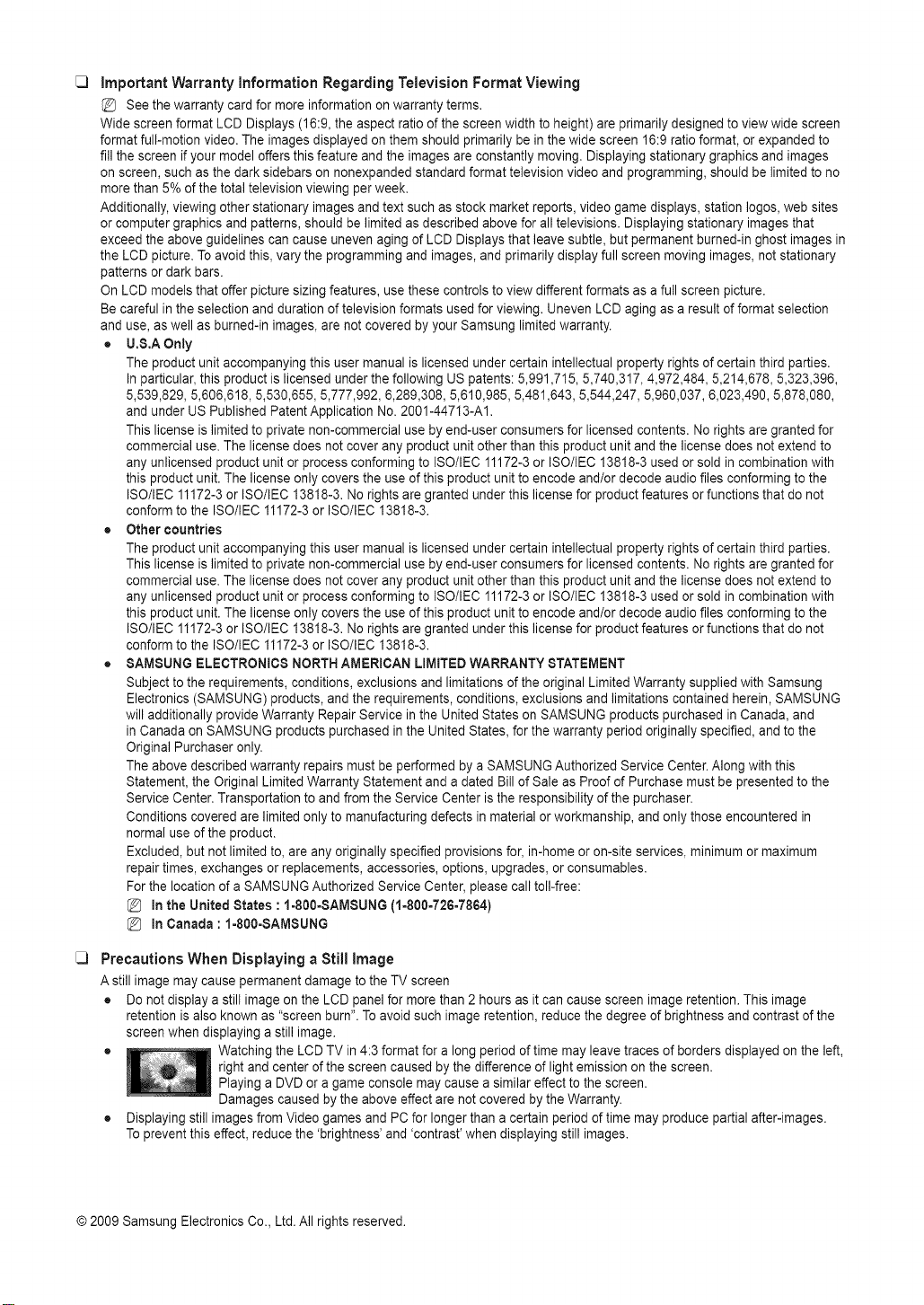
• Watching the LCD TV in 4:3 format for a long period of time may leave traces of borders displayed onthe left,
• Displaying still images from Video games and PC for longer than a certain period of time may produce partial after-images.
To prevent this effect, reduce the 'brightness' and 'contrast' when displaying still images.
© 2009 Samsung Electronics Co., Ltd. All rights reserved.
right and center ofthe screen caused by the difference of light emission on the screen.
Playing a DVD or a game console may cause a similar effect to the screen.
Damages caused by the above effect are not covered by the Warranty.
CONTENTS
•.List of Features..................................................... 2 ..Configunng theChannel Menu........................... 23
,,.Accessories..........................................................................2 .. ManagingChannels............................................................23
•.Viewing the Control Panel....................................................3
•,'Viewingthe ConnectionPanel..............................................4
•"Remote Control....................................................................6
=InstailingBatteriesin the RemoteControl............................6 =Configuring the PictureMenu............................... 25
=ConnectingVHFlea;dUHFAntennas.................................
" Connecting
" Connectinga DVDI Blu-rayplayert CableBoxJ =ConfiguringtheSoundMenu............................. 29
Satellitereceiver(Set-TopBox]viaHDMI.............................. 8
,,',,Connectinga DVDt Blu-rayplayerI CableBox/
Satellitereceiver Set-TopBox)via DV ...............................9
•,'Connectinga DVDt Blu-rayplayer I CableBoxt ,,'.Configuringthe Setup Menu.............................. 30
Satellitereceiver Set-TopBox)via Componentcables.......9
" Connectinga VCR..............................................................10
" Connectinga DigitalAudioSystem ....................................10
•"Connectingan Amplifiert DVD HomeTheater...................11 " Configuring the Input Menu............................... 34
" Connectinga Camcorder....................................................12 " ConfiguringtheSupport Menu........................... 34
•,'Connectinga PC.................................................... 13
" UsingYourTVas a Computer(PC) Display.......................27
,.Setting up the TVwith your PC........................................28
" ConnectingVHF and UHFAntennas..................................14 " Setting UpAnynet..............................................................36
" ConnectingCable TV.........................................................14 " SwitchinguetweenAnynet Devices..................................37
" Connectinga DVD1Blu-rayplayert CableBoxt " Recording...........................................................................38
Satellitereceiver(Set-TopBox]viaHDMI................................15 " Listeningthrough a Receiver Home theater .....................38
•"Connectinga DVD t Blu-rayplayert CableBox " Troubleshootingfor AnynetT...............................................39
Satellitereceiver Set-TopBox)via DVl .............................16
=Connectinga DVD/ Blu-raypJayert CableBox1
Satellitereceiver Set-TopBox)viaComponentcables........16
..ConnectingaVCR.............................................. 17 ,,'Troubleshooting..................................................................40
" Connectinga DigitalAudioSystem ....................................17 " Installingthe Stand............................................. 41
" ConnectinganAmplifierI DVDHomeTheater...................18 " DisconnectingtheStand.............................. 41
" Connectinga Camcorder....................................................19
,.Connectinga PC ...................................... 20
•,'Viewingthe menus.............................................................21
,,,Plug& Play Feature............................................................22
" ConnectingAnynet+ Devices.............................................35
+
,,,WallMount Kit Specifications(VESA) ......................42
•"UsingtheAnti-Theft KensingtonLock ......................42
" Securing the TV to the Wall ................................................43
=Specifications.....................................................................44
" Dimensions.........................................................................45
License
SRS (0) TruSurround HD, SRS and (e:) Symbol are trademarks of SRS Labs, Inc.
D _ _ _ T A L
TruSurround HD technology is incorporated under license from SRS Labs, Inc.
DOLBY Manufactured under license from Dolby Laboratories. Dolby and the double-D symbol are trademarks
D|Ei|TAL I of Dolby Laboratories.
_3
Symbol
Note One-TouchButton TOOLButton
Figures and illustrations in this User Manual are provided for reference only and maydiffer from actual productappearance.
Product design and specifications may be changed without notice in order to enhance product performance.
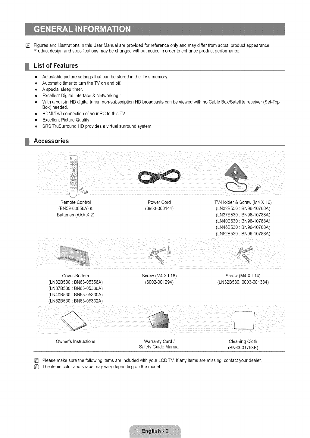
List of Features
• Adjustable picture settings that can bestored inthe TV's memory.
• Automatic timer to turn the TV on and off.
• Aspecial sleep timer.
• Excellent Digital Interface & Networking :
• With a built-in HD digital tuner, non-subscription HD broadcasts can be viewed with no Cable Box/Satellite receiver (Set-Top
Box) needed.
• HDMI/DVl connection of your PC to this TV.
• Excellent Picture Quality
• SRS TruSurround HD provides a virtual surround system.
Accessories
Remote Control Power Cord TV-Holder & Screw (M4 X 16)
(BN59-00856A) & (3903-000144) (LN32B530 : BN96-I 0788A)
Batteries (AAA X 2) (LN37B530 : BN96-I 0788A)
(LN40B530 : BN96-10788A)
(LN46B530 : BN96-10788A)
(LN52B530 :BN96-10788A)
i
Cover-Bottom Screw (M4 X L16) Screw (M4 X L14)
(LN32B530 •BN63-05356A) (6002-001294) (LN32B530: 6003-001334)
(LN37B530 •BN63-05330A)
(LN40B530 •BN63-05330A)
(LN52B530 •BN63-05332A)
J
Owner's Instructions
Warranty Card / Cleaning Cloth
Safety Guide Manual (BN63-01798B)
Please make sure the following items are included withyour LCD TV. If any items are missing, contact your dealer.
The items color and shape may vary depending on the model.
Viewing the Control Panel
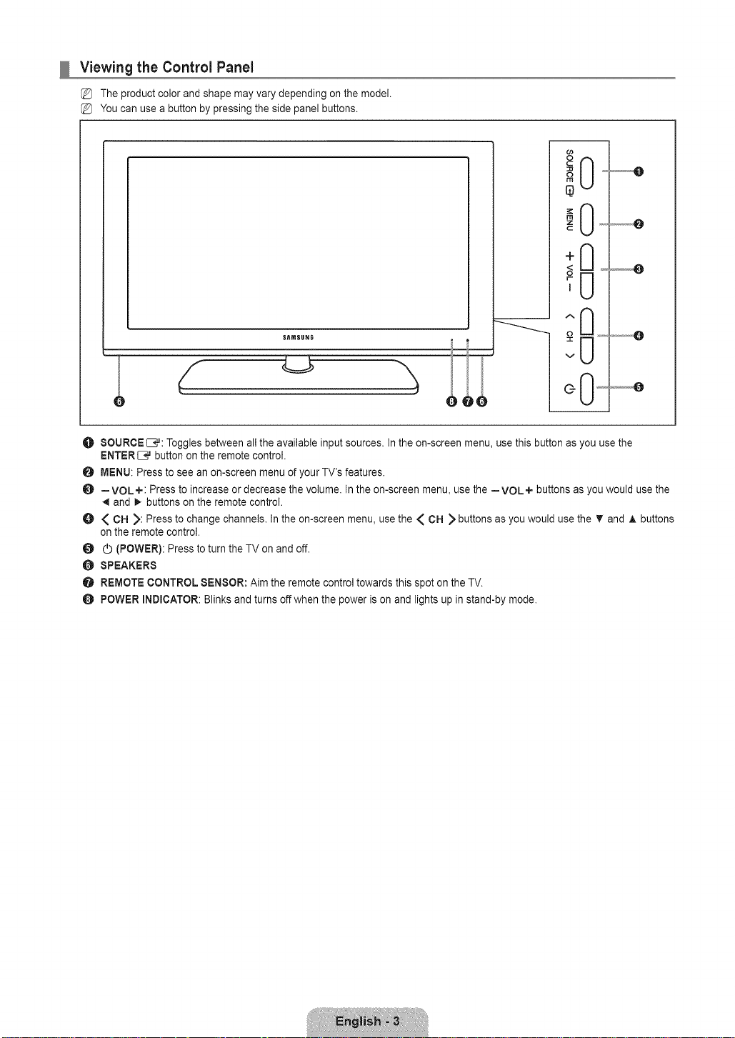
The product color and shape may vary depending on the model.
You can use a button by pressing the side panel buttons.
T
SItMSgHG
2
v
..............O
G
O SOURCE E},_:Toggles between all the available input sources. In the on-screen menu, use this button as you use the
ENTERIB,,Jbutton on the remote control.
O MENU: Press to see an on-screen menu of your TV's features.
O --VOL+: Press to increase or decrease the volume. In the on-screen menu, use the --VOL+ buttons asyou would use the
and _ buttons on the remote control.
O { CH ): Press to change channels. In the on-screen menu, use the { CH ) buttons asyou would use the _r and A buttons
on the remote control.
_ (POWER): Press to turn the TV on and off.
SPEAKERS
O REMOTE CONTROL SENSOR: Aim the remote control towards this spot on the TV.
O POWER INDICATOR: Blinks and turns offwhen the power is on and lights up in stand-by mode.
Viewing the Connection Panel
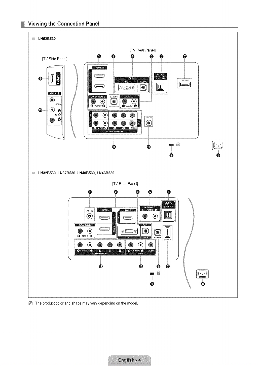
;;;;;i,_LN52B530
[TV Side Panel]
[TV Rear Panel]
, O O q
Ii® ®1® ® ®]
...
LN32B530, LN37B630, LN40B530, LN46B530
® _!_1/® ®Iml
__ r_
INK _
...........J
® ®
[TV Rear Panel]
SERWCE
:: ;.................................................................................7:ttr _:;:_..........................
\ .... "_='3.,",=77"_'..... "="-'_. _=_
.....................................................................f
The product color and shape may vary depending on the model.
_a
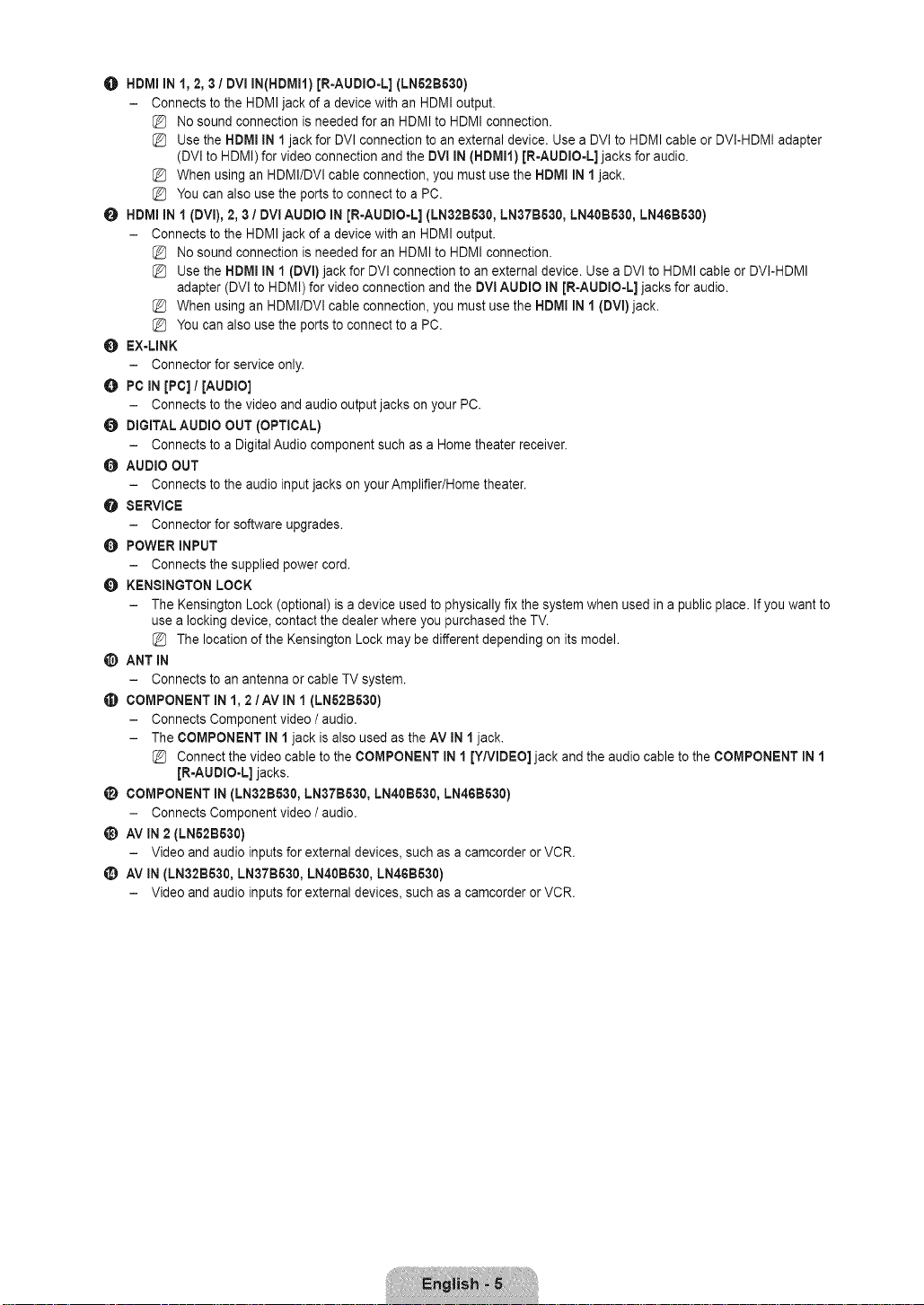
HDMI IN I,2,3 /DVlIN(HDMH) [R-AUDIO-L](LNB2BB30)
- Connects to the HDMIjack of a device with an HDMI output.
No sound connection is needed for an HDMI to HDMI connection.
Use the HDMI IN 1jack for DVl connection to an external device. Use a DVl to HDMI cable orDVI-HDMI adapter
(DVl to HDMI) for video connection and the DVI IN (HDMI1) JR-AUDIO-L] jacks foraudio.
When using an HDMI/DVl cable connection, you must use the HDMI IN 1 jack.
_Z] You can also use the ports to connect to a PC.
O HDMI IN 1 (DVI), 2, 3 / DVI AUDIO IN [R-AUDIO-L] (LN32B530, LN37BB30, LN40BB30, LN46B530)
- Connects to the HDMIjack of a device with an HDMI output.
No sound connection is needed for an HDMI to HDMI connection.
Use the HDMI IN 1 (DVI) jack for DVl connection to anexternal device. Use a DVl to HDMI cable or DVI-HDMI
adapter (DVl to HDMI) for video connection and the DVI AUDIO IN [R-AUDIO-L] jacks for audio.
When using an HDMI/DVl cable connection, you must use the NDMI IN 1 (DVI) jack.
_Z] You can also use the ports to connect to a PC.
O EX-UNK
- Connector for service only.
O PC IN [PC]/[AUDIO]
- Connects to the video and audio output jacks on your PC.
O DIGITALAUDIO OUT (OPTICAL)
- Connects to a Digital Audio component such as a Home theater receiver.
O AUDIO OUT
- Connects to the audioinput jacks on your Amplifier/Home theater.
O SERVICE
- Connector for software upgrades.
O POWER INPUT
- Connects the supplied power cord.
O KENSINGTON LOCK
- The Kensington Lock (optional)is a device used to physically fix the system when used in a public place, if you want to
use a locking device, contact the dealer where you purchased the TV.
The location of the Kensington Lock may be different depending on its model.
_) ANT IN
- Connects to an antenna or cable TV system.
_) COMPONENT mN1, 2/AV mNI (LNB2BB30)
- Connects Component video / audio.
- The COMPONENT iN 1 jack is also used as the AV mN1jack.
Connect the video cable to the COMPONENT mN1 [Y/VIDEO] jack and the audio cable to the COMPONENT mN1
JR-AUDIO-L] jacks.
(i_ COMPONENT IN (LN32B530, LN37BB30, LN40BB30, LN46B530)
- Connects Component video / audio.
_) AV iN2 (LNB2BB30)
- Video and audio inputs for external devices, such asa camcorder or VCR.
_) AV IN(LN32BB30,LN37B530, LN40B530, LN46BB30)
- Video and audio inputs for external devices, such asa camcorder or VCR.
Remote Control
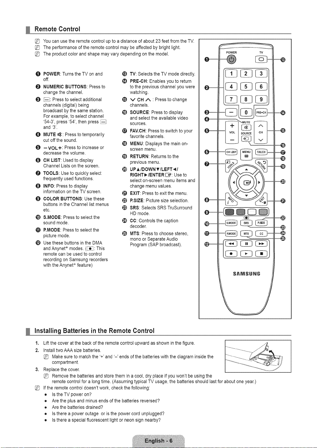
You can use the remote control up to a distance of about 23 feet from the TV.
The performance of the remote control may be affected by brightlight.
The product color and shape may vary depending on the model.
O POWER: Turns the TV on and
off.
O NUMERIC BUTTONS: Press to
change the channel.
_: Press to select additional
channels (digital) being
broadcast by the same station.
For example, to select channel
'54-3', press '54', then press
and '3'.
MUTE _:: Press to temporarily
cut off the sound.
--VOL+: Press to increase or
decrease the volume.
CH LIST: Used to display
Channel Lists on the screen.
O TOOLS: Use to quickly select
frequently used functions.
O INFO: Press to display
information on the TV screen.
O COLOR BUTTONS: Use these
buttons in the Channel list menus
etc.
&MODE: Press to select the
sound mode.
P.MODE: Press to select the
picture mode.
_i_ Usethese buttons in the DMA
andAnynet+ modes. ([_: This
remote can be used to control
recording on Samsung recorders
with the Anynet + feature)
_) TV: Selects the TV mode directly.
PRE-CH: Enables you to return
to the previous channel you were
watching.
_) v CH A : Press to change
channels.
O SOURCE: Press to display
and select the available video
sources.
FAV.CH:Press to switch to your
favorite channels.
_) MENU: Displays the main on-
screen menu.
_) RETURN: Returns to the
previous menu.
UP,_IDOWN T ILEFT _I
RIGHT_./ENTERIZ_,#:Use to
select on-screen menu items and
change menu values.
EXIT: Press to exit the menu.
!_) RSIZE: Picture size selection.
t_ SRS: Selects SRSTruSurround
HD mode.
¢0: Controls the caption
decoder.
I_ MT8: Press to choose stereo,
mono or Separate Audio
Program (SAP broadcast).
installing Batteries in the Remote Control
1,
Lift the cover at the back of the remote control upward as shown in the figure.
2.
Install two AAA size batteries.
Make sure to match the '+' and '-' ends of the batteries with the diagram inside the
compartment.
Replace the cover.
Remove the batteries and store them in a cool, dry place ifyou won't be using the
remote control for a long time. (Assuming typical TV usage, the batteries should last for about one year.)
%
If the remote control doesn't work, check the following:
• Is the TV power on?
• Are the plus and minus ends of the batteries reversed?
• Are the batteries drained?
• Is there a power outage or is the power cord unplugged?
• Is there a special fluorescent light or neon sign nearby?
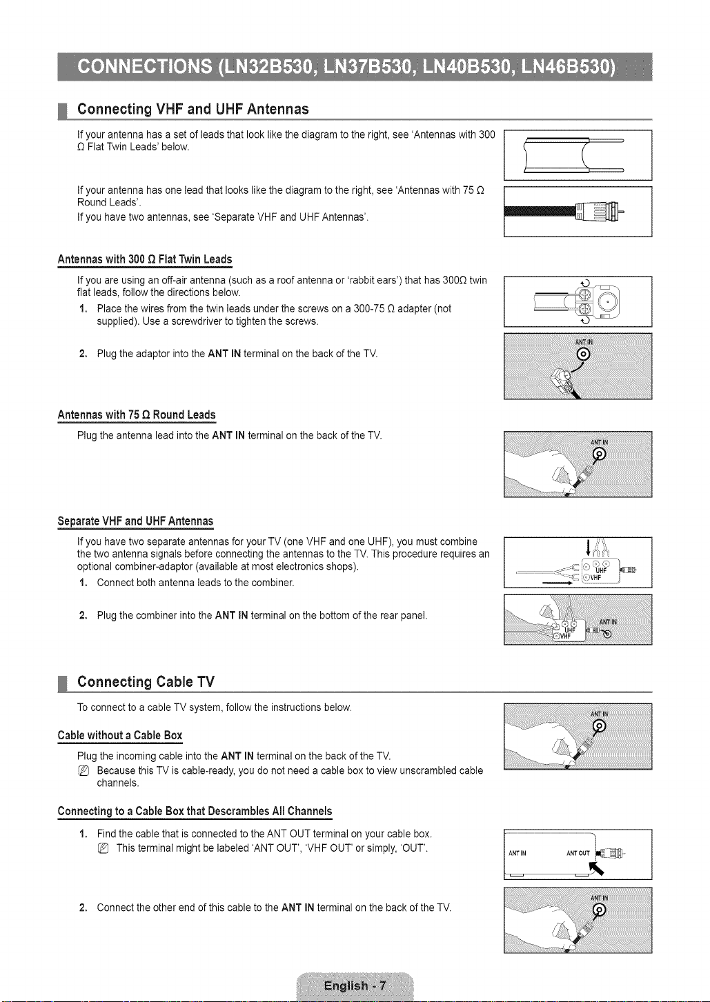
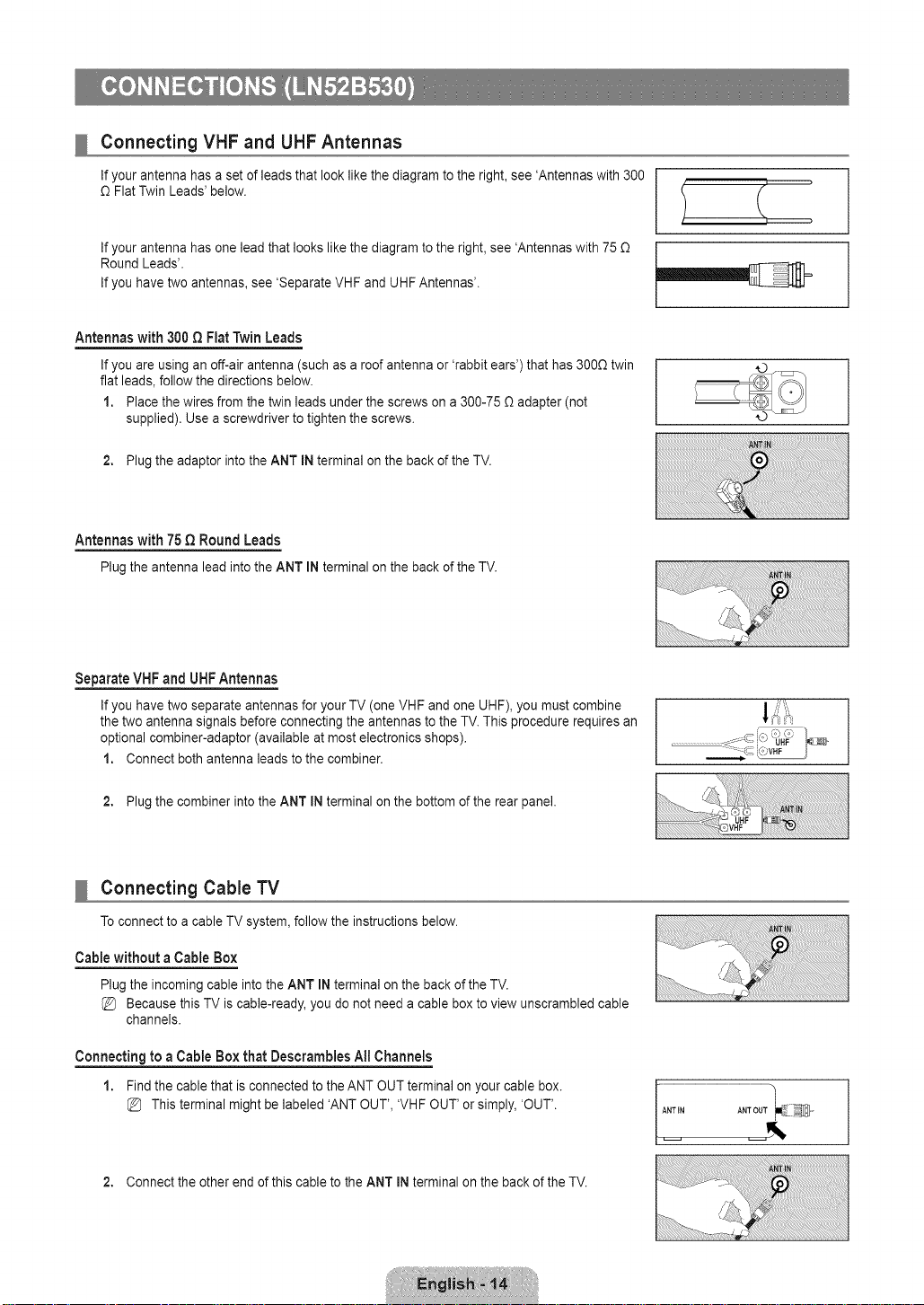
Connecting VHF and UHF Antennas
If your antenna has a set of leads that look like the diagram to the right, see 'Antennas with 300
£2Flat Twin Leads' below.
If your antenna has one lead that looks like the diagramto the right, see 'Antennas with 75 £2
Round Leads'.
If you have two antennas, see 'Separate VHF and UHF Antennas'.
Antennas with 300 Q Fiat Twin Leads
If you are using an off-air antenna (such asa roof antenna or 'rabbit ears') that has 3000 twin
flat leads, follow the directions below.
1. Place the wires from the twin leads under the screws on a 300-75 _ adapter (not
supplied). Use a screwdriver to tighten the screws.
2. Plug the adaptor into the ANT IN terminal on the back of the TV.
Antennaswith 75QRound Leads
PlugtheantennaleadintotheANTINterminalonthebackoftheTV.
]
]
Separate VHF and UHFAntennas
If you have two separate antennas foryour TV (one VHF and one UHF), you must combine
the two antenna signals before connecting the antennas to the TV. This procedure requires an
optional combiner-adaptor (available at most electronics shops).
1. Connect both antenna leads to the combiner.
2. Plug the combiner into the ANT INterminal on the bottom of the rear panel.
Connecting Cable TV
To connect to a cable TV system, follow the instructions below.
Cable without a Cable Box
Plug the incoming cable into the ANT IN terminal on the back of the TV.
Because this TV is cable-ready, you do not need a cable box to view unscrambled cable
channels.
Connecting to a Cable Box that Descrarables All Channels
1. Find the cable that is connected to the ANT OUT terminal on your cable box.
This terminal might be labeled 'ANT OUT', 'VHF OUT' or simply, 'OUT'.
2. Connect the other end of this cable to the ANT iNterminal on the back of the TV.
uu
..............................................................
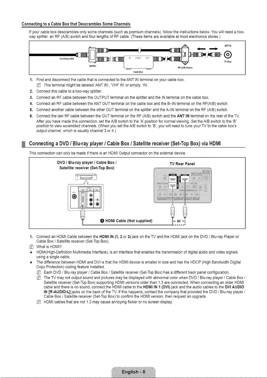
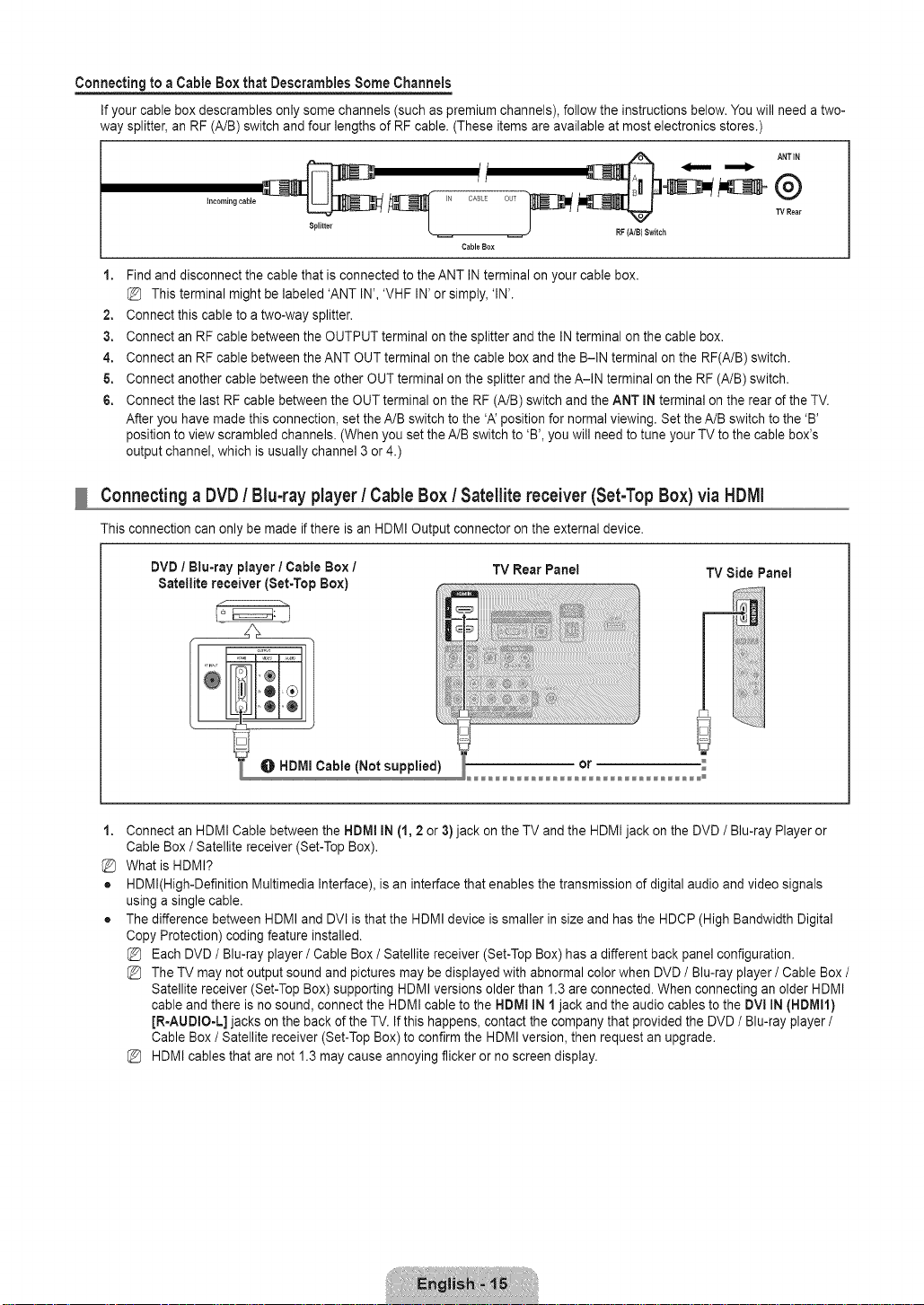
Connecting to a Cable Box that Descrarnbles Some Channels
If your cable box descrambles only some channels (such as premium channels), follow the instructions below. You will need atwo-
way splitter,an RF (A/B) switch and four lengths of RF cable. (These items are available at most electronics stores.)
t I
OASL O J/
CableBox
RF(NB} Switch
TVRear
1. Find and disconnect the cable that is connected to the ANT IN terminal on your cable box.
This terminal might be labeled 'ANT IN', 'VHF IN' or simply, 'IN'.
2. Connect this cable to a two-way splitter.
3. Connect an RF cable betweenthe OUTPUT terminal on the splitter and the IN terminal on the cable box.
4. Connect an RF cable betweenthe ANT OUT terminal on the cable box and the B-IN terminal on the RF(A/B) switch.
5. Connect another cable between the other OUT terminal onthe splitter and the A-IN terminal on the RF (A/B) switch.
6. Connect the last RF cable between the OUT terminal on the RF (A/B) switch and the ANT INterminal on the rear of the TV.
After you have made this connection, set the A/B switch to the 'A' position for normal viewing. Setthe A/B switch to the 'B'
position to view scrambled channels. (When you set the A/B switch to 'B', you will need to tune your TV to the cable box's
output channel, which is usually channel 3 or 4.)
Connecting a DVD / Blu-ray player / Cable Box / Satellite receiver (Set-Top Box) via HDFAI
This connection can only be made if there is an HDMI Output connector on the external device.
DVD / Blu-ray player / Cable Box I TV Rear Panel
Satellite receiver (Set-Top Box)
_HDMI Cable (Not supplied)
1. Connect an HDMI Cable between the HDM! IN (1, 2 or 3)jack on the TV and the HDMI jack on the DVD / Blu-ray Player or
Cable Box / Satellite receiver (Set-Top Box).
What is HDMI?
• HDMl(High-Definition Multimedia Interface), is an interface that enables the transmission of digital audio and video signals
using a single cable.
• The difference between HDMI and DVl is thatthe HDMI device is smaller insize and has the HDCP (High Bandwidth Digital
Copy Protection) coding feature installed.
Each DVD/ Blu-ray player / Cable Box / Satellite receiver (Set-Top Box) has a different back panel configuration.
The TV may not output sound and pictures may be displayed with abnormal color when DVD / Blu-ray player / Cable Box /
Satellite receiver (Set-Top Box) supporting HDMI versions older than 1.3are connected. When connecting an older HDMI
cable and there is no sound, connect the HDMI cable to the HDM! IN 1 (DVl) jack andthe audio cables to the DVI AUDIO
IN JR-AUDIO-L] jacks on the back of the TV. If this happens, contact the company that provided the DVD / Blu-ray player /
Cable Box / Satellite receiver (Set-Top Box) to confirm the HDMI version, then request an upgrade.
HDMI cables that are not 1.3 may cause annoying flicker or no screen display.
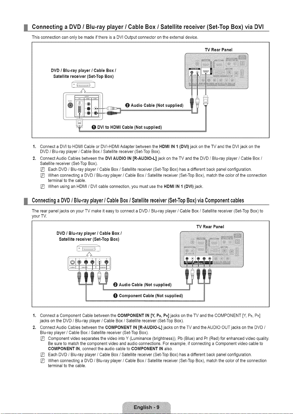
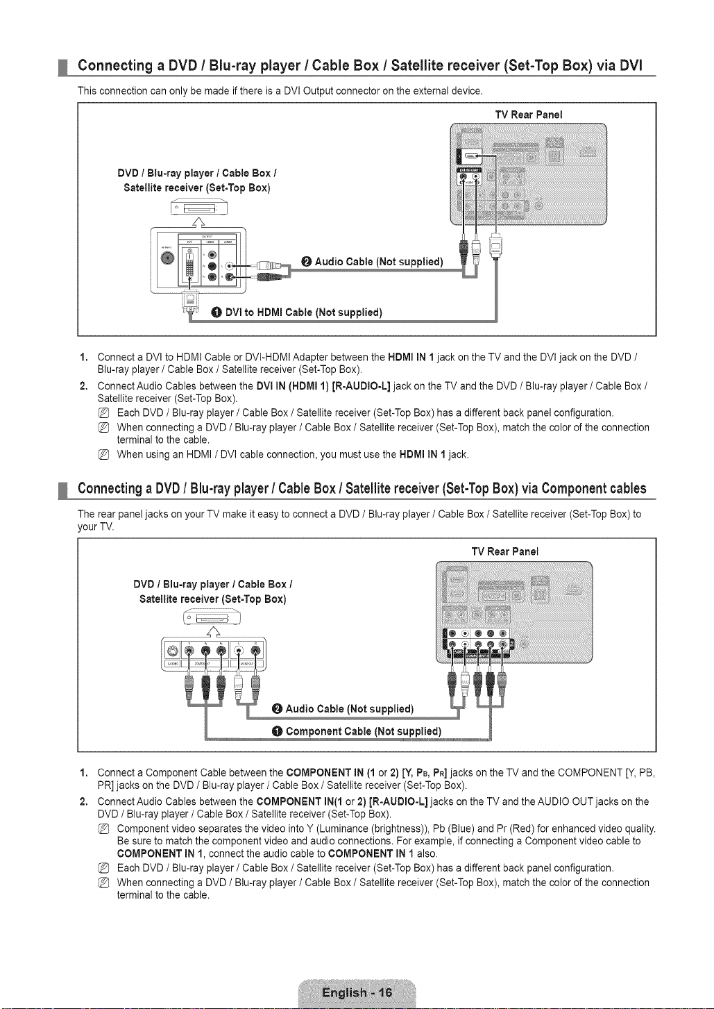
Connecting a DVD / Blu-ray player / Cable Box / Satellite receiver (Set-Top Box) via DVI
This connection can only be made if there is a DVI Output connector on the external device.
TV Rear Panet
DVD / Blu=ray player / Cable Box 1
Satellite receiver (Set=TopBox)
1,
Connect a DVI to HDMI Cable or DVI-HDMIAdapter between the HDMI IN 1 (DVI) jack on the TV and the DVI jack on the
DVD / Blu-ray player / Cable Box / Satellite receiver (Set-Top Box).
2,
Connect Audio Cables between the DVl AUDIO IN [R-AUDIO-L] jack on the TV and the DVD / Blu-ray player / Cable Box/
Satellite receiver (Set-Top Box).
Each DVD/ Blu-ray player / Cable Box / Satellite receiver (Set-Top Box) has a different back panel configuration.
When connecting a DVD / Blu-ray player / Cable Box / Satellite receiver (Set-Top Box), match the color of the connection
terminal to the cable.
When using an HDMI / DVI cable connection, you must use the HDMI IN 1 (DVl)jack.
Connectinga DVD/ Blu-rayplayer/ CableBox/Satellitereceiver(Set-TopBox)via Componentcables
The rear panel jacks on your TV make it easy to connect a DVD / Blu-ray player / Cable Box / Satellite receiver (Set-Top Box) to
your TV.
TV RearPanel
DVD / Blu=ray player / Cable Box /
Satellite receiver (Set=Top Box)
O Audio Cable (Not supplied)
O Component Cable (Not supplied)
1,
Connect a Component Cable between the COMPONENT IN [Y, PB,PR]jacks on the TV and the COMPONENT [Y, PB,PR]
jacks on the DVD / Blu-ray player / Cable Box / Satellite receiver (Set-Top Box).
2,
Connect Audio Cables between the COMPONENT iN JR=AUDIO-L]jacks on the TV and the AUDIO OUT jacks on the DVD /
Blu-ray player/Cable Box / Satellite receiver (Set-TopBox).
Component video separates the video into Y (Luminance (brightness)), Pb (Blue) and Pr (Red) for enhanced video quality.
Be sure to match the component video and audio connections. For example, if connecting a Component video cable to
COMPONENT IN, connect the audio cable to COMPONENT IN also.
Each DVD/ Blu-ray player / Cable Box / Satellite receiver (Set-Top Box) has a different back panel configuration.
When connecting a DVD / Blu-ray player / Cable Box / Satellite receiver (Set-Top Box), match the color of the connection
terminal to the cable.
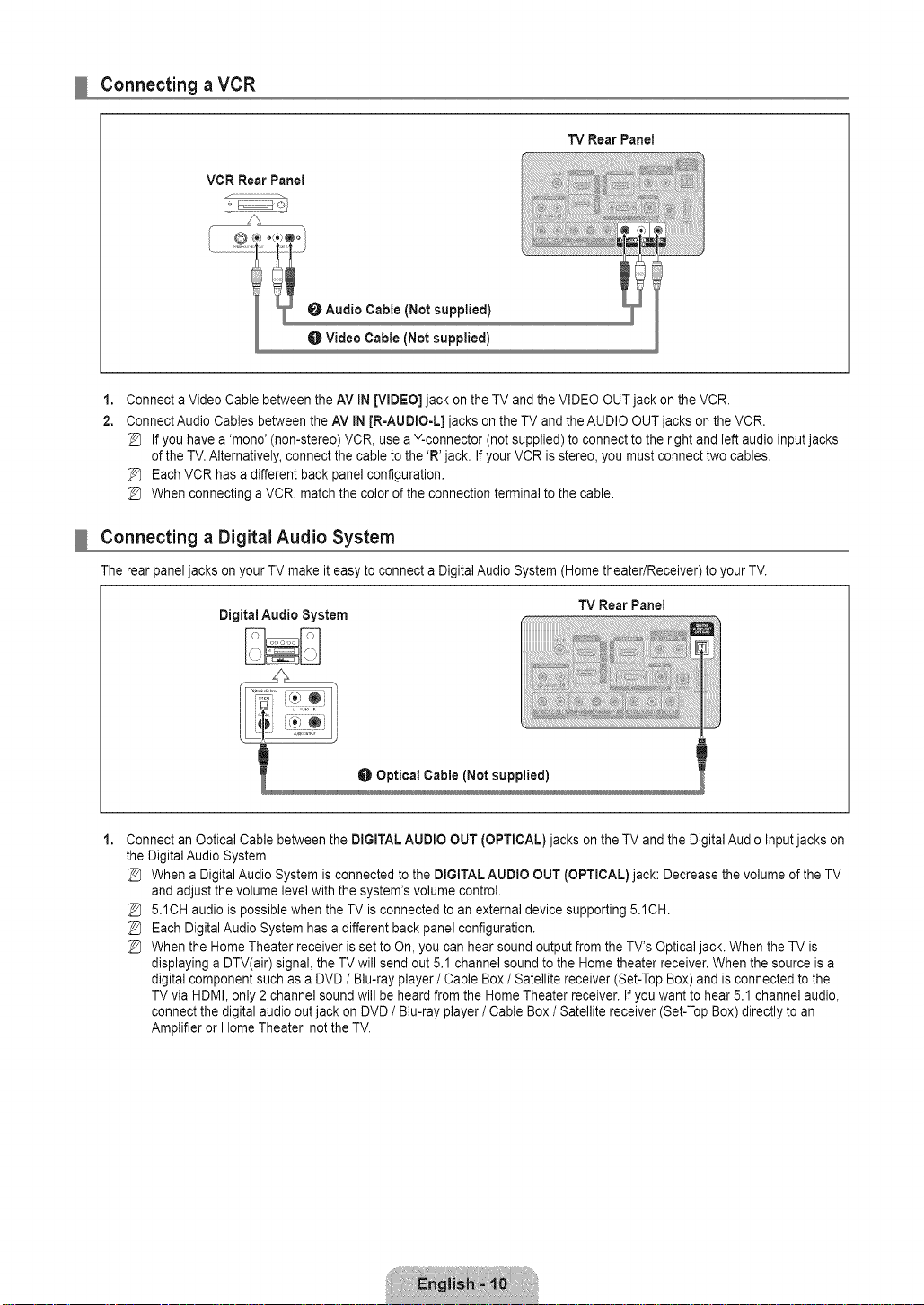
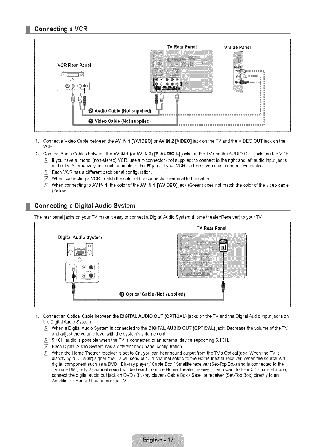
Connecting a VCR
TV RearPanei
VCR Rear Panel
O Audio Cable {Not supplied)
O Video Cable (Not supplied)
1,
Connect a Video Cable between the AV IN [VIDEO] jack onthe TV and the VIDEO OUT jack on the VCR.
2,
Connect Audio Cables between the AV IN JR-AUDIO-L] jacks on the TV and the AUDIO OUT jacks onthe VCR.
If you have a 'mono' (non-stereo) VCR, usea Y-connector (not supplied) to connect to the right and left audio input jacks
of the TV.Alternatively, connect the cable to the 'R' jack. If your VCR is stereo, you must connect two cables.
Each VCR has a different back panel configuration.
When connecting a VCR, match the color of the connection terminal to the cable.
Connecting a Digital Audio System
The rear panel jacks on your TV make it easy to connect a Digital Audio System (Home theater/Receiver) to your TV.
Digital Audio System TV Rear Panel
Connect an Optical Cable between the DIGITAL AUDIO OUT (OPTICAL) jacks on the TV and the Digital Audio Input jacks on
the Digital Audio System.
When a Digital Audio System is connected to the DIGITAL AUDIO OUT (OPTICAL) jack: Decrease the volume of the TV
and adjust the volume level with the system's volume control.
5.1CH audio is possible when the TV is connected to an external device supporting 5.1CH.
Each Digital Audio System has a different back panel configuration.
When the Home Theater receiver is set to On, you can hear sound output from the TV's Opticaljack. When the TV is
displaying a DTV(air) signal, the TV will send out 5.1 channel sound to the Home theater receiver. When the source is a
digital component such as a DVD / Blu-ray player / Cable Box / Satellite receiver (Set-Top Box) and isconnected to the
TV via HDMI, only 2 channel sound will be heard from the Home Theater receiver. If you want to hear 5.1 channel audio,
connect the digital audio out jack on DVD/ Blu-ray player / Cable Box / Satellite receiver (Set-Top Box) directly to an
Amplifier or Home Theater, not the TV.
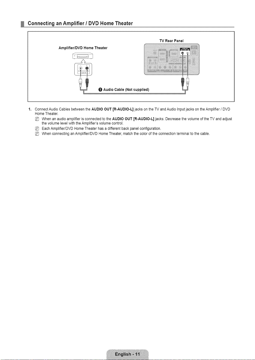
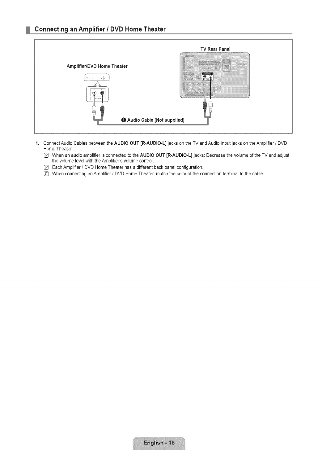
Connecting an Amplifier / DVD Home Theater
TV Rear Panel
Ampiifier/DVD Home Theater
Connect Audio Cables between the AUDIO OUT [R-AUDIO-L] jacks on theTV and Audio Inputjacks on theAmplifier / DVD
Home Theater.
When an audio amplifier is connected to the AUDIO OUT [R-AUDIO-L] jacks: Decrease the volume of the TV and adjust
the volume level with theAmplifier's volume control.
Each Amplifier/DVD HomeTheater has a different back panel configuration.
When connecting anAmplifier/DVD HomeTheater, match the color of the connection terminal to the cable.

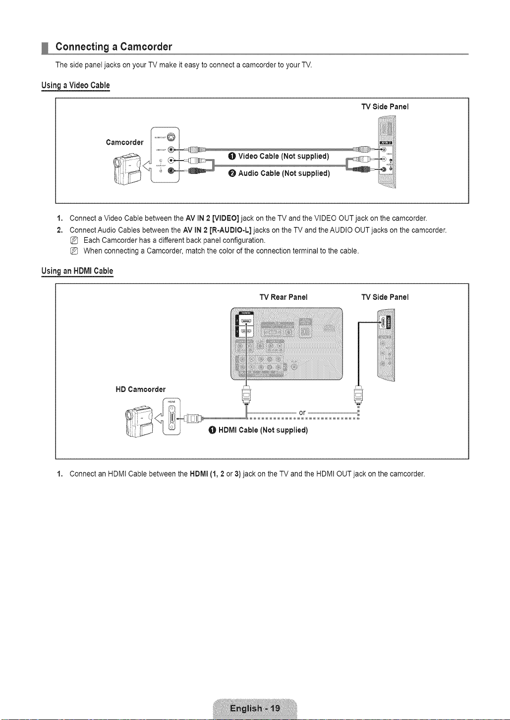
Connecting a Camcorder
Using aVideo Cable
TV Rear Panel
Camoorder
0 Audio Cable (Not supplied]
Video Cable (Not supplied)
1,
Connect a Video Cable between the AV IN [VIDEO] jack onthe TV and the VIDEO OUT jack on the camcorder.
2.
Connect Audio Cables between the AV IN [R-AUDIO-L] jacks on the TV and the AUDIO OUT jacks on the camcorder.
Each Camcorder has a different back panel configuration.
When connecting a Camcorder, match the color of the connection terminal to the cable.
UsinganHDIVllCable
TV Rear Panel
HD Camcorder
or
1. Connect an HDMI Cable between the HDMI IN [1, 2 or 3)jack on the TV and the HDMI OUT jack on the camcorder.
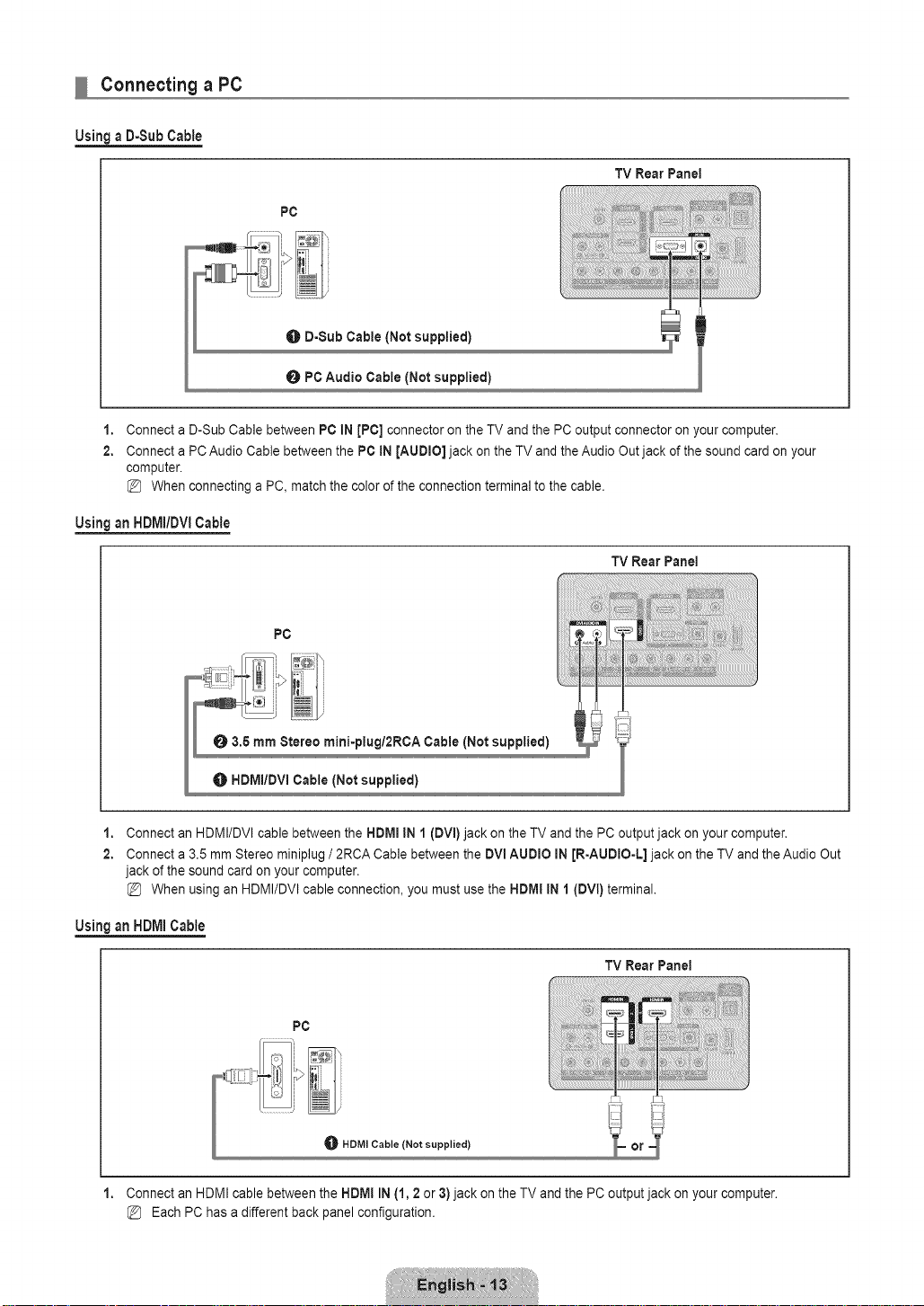
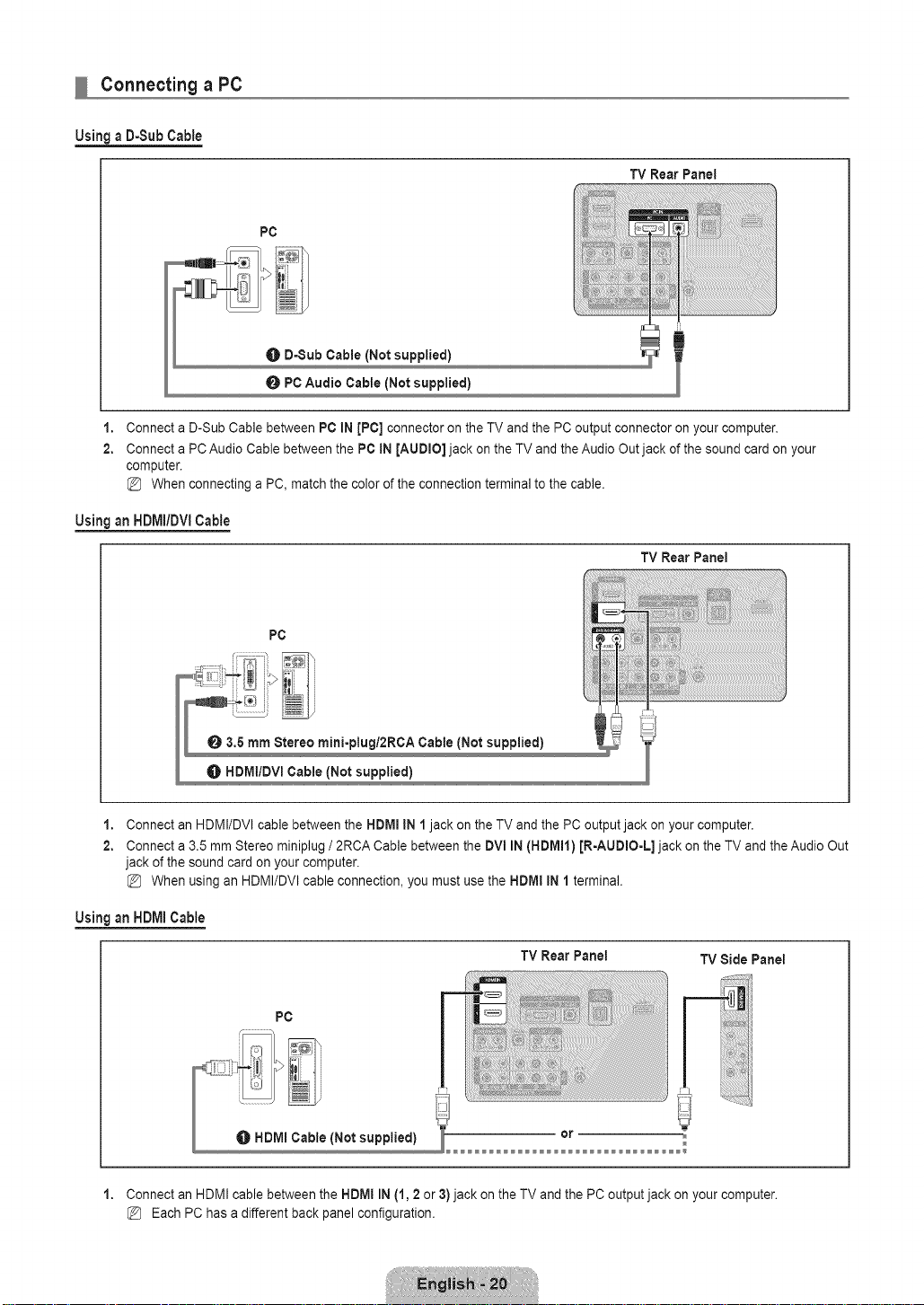
Connecting a PC
Usinga D-Sub Cable
TV Rear Panel
PC
O D-Sub Cable (Not supplied)
O PC Audio Cable (Not supplied)
1,
Connect a D-Sub Cable between PC IN [PC] connector on the TV and the PC output connector onyour computer.
2,
Connect a PCAudio Cable between the PC IN [AUDIO] jack on the TV and the Audio Out jack of the sound card on your
computer.
When connecting a PC, match the color of the connection terminal to the cable.
UsinganHDIVlI/DVlCable
TV Rear Panel
PC
II o mmS, min,-p,ug,2RCACab,e<Notsupplied/
_ HDMm/DVmCable (Not supplied)
1,
Connect an HDMI/DVI cable between the HDMmIN 1 (DVm)jack on the TV and the PC output jack onyour computer.
2,
Connect a 3.5 mm Stereo miniplug / 2RCA Cable between the DVl AUDIO mN[R-AUDIO-L] jack on the TV and theAudio Out
jack of the sound card on your computer.
When using an HDMI/DVI cable connection, you must use the HDIVIIIN I (DVl) terminal.
Using an HDMI Cable
TV Rear Panel
PC
1. Connect an HDMI cable between the HDMI IN (1,2 or 3) jack on the TV and the PC output jack on your computer.
Each PChas a different back panel configuration.
Connecting VHF and UHF Antennas
If your antenna has a set of leads that look like the diagram to the right, see 'Antennas with 300
£2Flat Twin Leads' below.
If your antenna has one lead that looks like the diagramto the right, see 'Antennas with 75 £2
Round Leads'.
If you have two antennas, see 'Separate VHF and UHF Antennas'.
Antennas with 300 Q Fiat Twin Leads
If you are using an off-air antenna (such asa roof antenna or 'rabbit ears') that has 3000 twin
flat leads, follow the directions below.
1. Place the wires from the twin leads under the screws on a 300-75 _ adapter (not
supplied). Use a screwdriver to tighten the screws.
2. Plug the adaptor into the ANT IN terminal on the back of the TV.
Antennaswith 75QRound Leads
PlugtheantennaleadintotheANTINterminalonthebackoftheTV.
]
Separate VHF and UHFAntennas
If you have two separate antennas foryour TV (one VHF and one UHF), you must combine
the two antenna signals before connecting the antennas to the TV. This procedure requires an
optional combiner-adaptor (available at most electronics shops).
1. Connect both antenna leads to the combiner.
2. Plug the combiner into the ANT INterminal on the bottom of the rear panel.
Connecting Cable TV
To connect to a cable TV system, follow the instructions below.
Cable without a Cable Box
Plug the incoming cable into the ANT IN terminal on the back of the TV.
Because this TV is cable-ready, you do not need a cable box to view unscrambled cable
channels.
Connecting to a Cable Box that Descrarnbles All Channels
1. Find the cable that is connected to the ANT OUT terminal on your cable box.
This terminal might be labeled 'ANT OUT', 'VHF OUT' or simply, 'OUT'.
2. Connect the other end of this cable to the ANT iNterminal on the back of the TV.
..............................................................
Connecting to a Cable Box that Descrambles Some Channels
If your cable box descrambles only some channels (such as premium channels), follow the instructions below. You will need atwo-
way splitter,an RF (A/B) switch and four lengths of RF cable. (These items are available at most electronics stores.)
ANT IN
Incomingcable
Splitter
CableBox
RF(NB) Switch
"iVRear
1. Find and disconnect the cable that is connected to the ANT IN terminal on your cable box.
This terminal might be labeled 'ANT IN', 'VHF IN' or simply, 'IN'.
2. Connect this cable to a two-way splitter.
3. Connect an RF cable betweenthe OUTPUT terminal on the splitter and the IN terminal on the cable box.
4. Connect an RF cable betweenthe ANT OUT terminal on the cable box and the B-IN terminal on the RF(A/B) switch.
5. Connect another cable between the other OUT terminal onthe splitter and the A-IN terminal on the RF (A/B) switch.
6. Connect the last RF cable between the OUT terminal on the RF (A/B) switch and the ANT INterminal on the rear of the TV.
After you have made this connection, set the A/B switch to the 'A' position for normal viewing. Setthe A/B switch to the 'B'
position to view scrambled channels. (When you set the A/B switch to 'B', you will need to tune your TV to the cable box's
output channel, which is usually channel 3 or 4.)
Connecting a DVD / Blu-ray player / Cable Box / Satellite receiver (Set-Top Box) via HDMI
This connection can only be made if there is an HDMI Output connector on the external device.
DVD/ Blu-ray player / Cable Box /
Satellite receiver (Set-Top Box)
TV Rear Panel TV Side Panel
__Cable (Not supplied)
or
1. Connect an HDMI Cable between the HDM! IN (1, 2 or 3)jack on the TV and the HDMI jack on the DVD / Blu-ray Player or
Cable Box / Satellite receiver (Set-Top Box).
What is HDMI?
• HDMl(High-Definition Multimedia Interface), is an interface that enables the transmission of digital audio and video signals
using a single cable.
• The difference between HDMI and DVl is thatthe HDMI device is smaller insize and has the HDCP (High Bandwidth Digital
Copy Protection) coding feature installed.
Each DVD/ Blu-ray player / Cable Box / Satellite receiver (Set-Top Box) has a different back panel configuration.
The TV may not output sound and pictures may be displayed with abnormal color when DVD / Blu-ray player / Cable Box /
Satellite receiver (Set-Top Box) supporting HDMI versions older than 1.3are connected. When connecting an older HDMI
cable and there is no sound, connect the HDMI cable to the HDMI IN 1jack and the audio cables to the DVi IN (HDMI1)
[R-AUDIO-L] jacks on the back of the TV. Ifthis happens, contact the company that provided the DVD / Blu-rayplayer /
Cable Box / Satellite receiver (Set-Top Box) to confirm the HDMI version, then request an upgrade.
HDMI cables that are not 1.3 may cause annoying flicker or no screen display.
Connecting a DVD / Blu-ray player / Cable Box / Satellite receiver (Set-Top Box) via DVI
This connection can only be made if there is a DVI Output connector on the external device.
TV Rear Panel
DVD / Blu=ray player / Cable Box 1
Satellite receiver (Set=TopBox)
1,
Connect a DVI to HDMI Cable or DVI-HDMIAdapter between the NDMI IN 1jack onthe TV and the DVIjack on the DVD/
Blu-ray player/Cable Box / Satellite receiver (Set-TopBox).
2.
Connect Audio Cables between the DVl IN (HDMI 1) JR=AUDIO-L]jack on the TV and the DVD / Blu-ray player/Cable Box /
Satellite receiver (Set-Top Box).
Each DVD/ Blu-ray player / Cable Box / Satellite receiver (Set-Top Box) has a different back panel configuration.
When connecting a DVD / Blu-ray player / Cable Box / Satellite receiver (Set-Top Box), match the color of the connection
terminal to the cable.
When using an HDMI / DVI cable connection, you must use the NDMI IN 1 jack.
Connecting a DVD/ Blu-ray player/ Cable Box / Satellite receiver (Set-TopBox)via Component cables
The rear paneljacks on yourTV makeiteasyto connecta DVD/Biu-ray player/Cable Box/Satellite receiver(Set-Top Box)to
your TV.
TV RearPanel
DVD / Blu=ray player / Cable Box /
Satellite receiver (Set=TopBox)
O Audio Cable {Not supplied)
O Component Cable (Not supplied)
1,
Connect a Component Cable between the COMPONENT IN (1 or 2) [Y, PB,PR]jacks on the TV andthe COMPONENT [Y, PB,
PR]jacks on the DVD/ Blu-ray player / Cable Box / Satellite receiver (Set-Top Box).
2.
Connect Audio Cables between the COMPONENT IN(1 or 2) JR=AUDIO-L]jacks on the TV and the AUDIO OUT jacks on the
DVD / Blu-ray player / Cable Box / Satellite receiver (Set-Top Box).
Component video separates the video into Y (Luminance (brightness)), Pb (Blue) and Pr (Red) for enhanced video quality.
Be sure to match the component video and audio connections. For example, if connecting a Component video cable to
COMPONENT IN 1, connect the audio cable to COMPONENT IN 1 also.
Each DVD/ Blu-ray player / Cable Box / Satellite receiver (Set-Top Box) has a different back panel configuration.
When connecting a DVD / Blu-ray player / Cable Box / Satellite receiver (Set-Top Box), match the color of the connection
terminal to the cable.
Connecting a VCR
TV RearPanet
VCR Rear Panel
Video Cable (Not supplied)
1,
Connect a Video Cable between the AV IN 1 [Y/VIDEO] or AV IN 2 [VIDEO) jack on the TV and the VIDEO OUT jack on the
VCR.
2,
Connect Audio Cables between the AV IN 1 (orAV IN 2) [R-AUDIO-L] jacks on the TV and the AUDIO OUTjacks on the VCR.
If you have a 'mono' (non-stereo) VCR, usea Y-connector (not supplied) to connect to the right and left audio input jacks
of the TV.Alternatively, connect the cable to the 'R' jack. If your VCR is stereo, you must connect two cables.
Each VCR has a different back panel configuration.
When connecting a VCR, match the color of the connection terminal to the cable.
When connecting to AV IN 1, the color of the AV IN 1 [YNIDEO] jack (Green) does not match the color of the video cable
(Yellow).
TV Side Panel
Connecting a Digital Audio System
The rear panel jacks on your TV make it easy to connect a Digital Audio System (Home theater/Receiver) to your TV.
TV Rear Panel
Digital Audio System
O Optical Cable (Not supplied)
Connect an Optical Cable between the DIGITAL AUDIO OUT (OPTICAL) jacks on the TV and the Digital Audio Input jacks on
the Digital Audio System.
When a Digital Audio System is connected to the DIGITAL AUDIO OUT (OPTICAL) jack: Decrease the volume of the TV
and adjust the volume level with the system's volume control.
5.1CH audio is possible when the TV is connected to an external device supporting 5.1CH.
Each Digital Audio System has a different back panel configuration.
When the Home Theater receiver is set to On, you can hear sound output from the TV's Opticaljack. When the TV is
displaying a DTV(air) signal, the TV will send out 5.1 channel sound to the Home theater receiver. When the source is a
digital component such as a DVD / Blu-ray player / Cable Box / Satellite receiver (Set-Top Box) and isconnected to the
TV via HDMI, only 2 channel sound will be heard from the Home Theater receiver. If you want to hear 5.1 channel audio,
connect the digital audio out jack on DVD/ Blu-ray player / Cable Box / Satellite receiver (Set-Top Box) directly to an
Amplifier or Home Theater, not the TV.
Connecting an Amplifier / DVD Home Theater
TV Rear Panel
Ampiifier/DVD Home Theater
Connect Audio Cables between the AUDIO OUT [RoAUDIO-L]jacks on the TV andAudio Inputjacks on the Amplifier / DVD
Home Theater.
When an audio amplifier is connected to the AUDIO OUT [RoAUDIO-L] jacks: Decrease the volume of the TV and adjust
the volume level with theAmplifier's volume control.
Each Amplifier / DVD HomeTheater has a different back panel configuration.
When connecting anAmplifier / DVD Home Theater, match the color of the connection terminal to the cable.
Connecting a Camcorder
The side panel jacks on your TV make it easy to connect a camcorder to your TV.
UsingaVideoCable
TV Side Panel
Camoorder
O Video Cable (Not supplied)
Audio Cable (Not supplied)
1,
Connect a Video Cable between the AV IN 2 [VIDEO] jack onthe TV and the VIDEO OUT jack on the camcorder.
2.
Connect Audio Cables between the AV IN 2 [R-AUDIO-L] jacks on the TV and the AUDIO OUT jacks on the camcorder.
Each Camcorder has a different back pane] configuration.
When connecting a Camcorder, match the color of the connection terminal to the cable.
UsinganHDIVllCable
TV Rear Panel TV Side Panel
HD Camcorder
1. Connect an HDMI Cable between the HDMI (t, 2 or 3) jack on theTV and the HDMI OUTjack on the camcorder.
Connecting a PC
Usinga D-Sub Cable
TV Rear Panel
PC
O D-Sub Cable (Notsupplied)
O PC Audio Cable(Notsupplied)
I,
Connect a D-Sub Cable between PC IN [PC] connector on the TV and the PC output connector onyour computer.
2,
Connect a PCAudio Cable between the PC iN [AUDIO] jack on the TV and the Audio Outjack of the sound card on your
computer.
When connecting a PC, match the color of the connection terminal to the cable.
UsinganHDIVlI/DVlCable
TV Rear Panel
PC
O 3,5 mm Stereo mini-plug/2RCA Cable (Not supplied)
HDMIIDVI Cable (Not supplied)
1,
Connect an HDMI/DVI cable between the HDMmIN 1 jack on the TV and the PC output jack on your computer.
2,
Connect a 3.5 mm Stereo miniplug / 2RCA Cable between the DVl IN (HDMH) [R-AUDmO-L]jack on the TV and the Audio Out
jack of the sound card on your computer.
When using an HDMI/DVI cable connection, you must use the HDIVIIIN I terminal.
UsinganHDIVllCable
TV RearPaneI
PC
["_ _::_!iJ (Not supplied)
TV Side Panel
1. Connect an HDMI cable between the HDMI IN (1,2 or 3) jack on the TV and the PC output jack on your computer.
Each PChas a different back panel configuration.
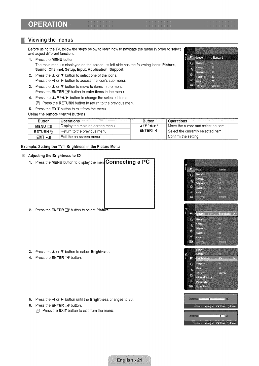
Viewing the menus
Before using the TV, follow the steps below to learn how to navigate the menu in order to select
and adjust different functions.
1. Press the MENU button.
The main menu is displayed on the screen. Its left side has the following icons: Picture,
Sound, Channel, Setup, input, Application, Support.
2. Press the A or T button to select one of the icons.
Press the 41or _. button to access the icon's sub-menu.
3. Press the A or T button to move to items in the menu.
Press the ENTERI:B_ button to enter items in the menu.
4. Press the A/'_/_I/_ button to change the selected items.
Press the RETURN button to return to the previous menu.
5. Press the EXIT button to exit from the menu.
Using the remote control buttons
MENU iTTI _Display the ma!n onlscreen menu. AI_'I_I_./ _nd select an item.
RETURN O he previous menu. ENTER IB_ _y selected item.
_ _:° [Confirm the setting.
Example:Settingthe TV'sBrightness in the PictureMenu
Adjusting the Brightness to 80
1. Press the MENU button to display the men Connecting a PC
2. Press the ENTER _ button to select Pict_ire.
3. Press the A or T button to select Brightness.
4. Press the ENTER_ button.
5. Press the _ or _ button until the Brightness changes to 80.
6. Press the ENTER[B# button.
Press the EXIT button to exit from the menu.
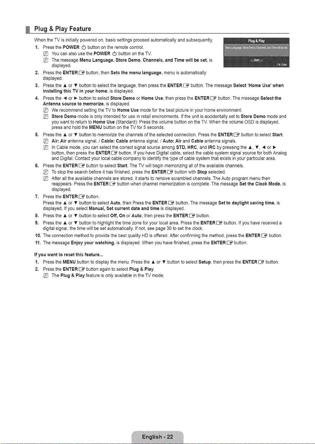
Plug & Play Feature
When the TV is initially powered on, basic settings proceed automatically and subsequently.
1. Press the POWER d) button onthe remote control.
You can also use the POWER (_ button on the TV.
The message Menu Language, Store Demo, Channels, and Time will be set. is
displayed.
2. Press the ENTER _,_ button, then Sets the menu language, menu is automatically
displayed.
3. Press the A or T button to select the language, then press the ENTER _,_ button. The message Select 'Home Use'when
installing this TV in your home. is displayed.
4. Press the _ or _. button to select Store Demo or Home Use, then press the ENTER _,_ button.The message Select the
Antenna source to memorize, is displayed.
We recommend setting the TV to Home Use mode for the best picture in your home environment.
Store Demo mode is only intended for use in retail environments. If the unit is accidentally set to Store Demo mode and
you want to return to Home Use (Standard): Press the volume button on the TV. When the volume OSD is displayed,
press and hold the MENU button onthe TV for 5 seconds.
5. Press the ,L or T button to memorize the channels of the selected connection. Press the ENTERI_--J,_ button to select Start.
Air: Air antenna signal. / Cable: Cable antenna signal. / Auto: Air and Cable antenna signals.
In Cable mode, you can select the correct signal source among 8TD, HRC, and IRC by pressing the A, T, _ or I_
button, then press the ENTER [B,_button. If you have Digital cable, select the cable system signal source for both Analog
and Digital. Contact your local cable company to identify the type ofcable system that exists in your particular area.
6. Press the ENTER EJ,_ button to select Start. The TV will begin memorizing all of the available channels.
To stop the search before ithas finished, press the ENTERI_--;,_button with Stop selected.
After all the available channels are stored, it starts to remove scrambled channels. The Auto program menu then
reappears. Press the ENTER _,_ button when channel memorization is complete. The message Set the Clock Mode. is
displayed.
7. Press the ENTERI:--;_button.
Press the A or T button to select Auto, then Press the ENTER_ button. The message Set to daylight saving time. is
displayed. If you select Manual, Set current date and time is displayed.
8. Press the A or T button to select Off, On or Auto, then press the ENTER C_ button.
9. Press the A or T button to highlight the time zone for your local area. Press the ENTERC_ button. Ifyou have received a
digital signal, the time will be set automatically. Ifnot, see page 30 to set the clock.
10, The connection method to provide the bestquality HD is offered. After confirming the method, press the ENTERC_ button.
11. The message Enjoy your watching, is displayed. When you have finished, press the ENTER C_ button.
If you want to reset this feature,.,
1. Press the MENU button to display the menu. Press the A or T button to select Setup, then press the ENTERC_ button.
2. Press the ENTERI:B# button again to select Plug & Play.
The Plug & Play feature is only available in the TV mode.
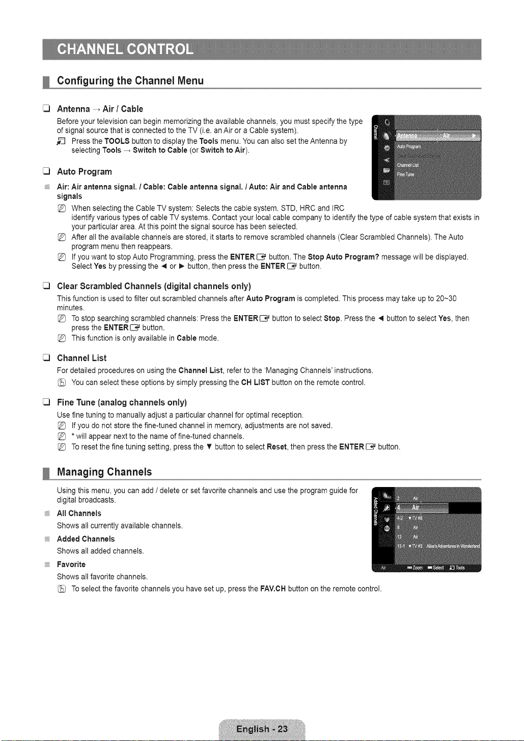
Configuring the Channel Menu
C) Antenna -, Air / Cable
Before your television can begin memorizing the available channels, you must specify the type
of signal source that is connected to the TV (i.e. anAir or a Cable system).
_-_ Press the TOOLS button to display the Tools menu. You can also set the Antenna by
selecting Tools _ Switch to Cable (or Switch to Air).
C3
Auto Program
Air: Air antenna signal. / Cable: Cable antenna signal, / Auto: Air and Cable antenna
signals
When selecting the Cable TV system: Selects the cable system. STD, HRC and IRC
identify various types of cable TV systems. Contact your local cable company to identify the type of cable system that exists in
your particular area. At this point the signal source has been selected.
After all the available channels are stored, itstarts to remove scrambled channels (Clear Scrambled Channels). The Auto
program menu then reappears.
If you want to stop Auto Programming, press the ENTER C3,.J button. The Stop Auto Program? message will be displayed.
Select Yes by pressing the _1or 1,, button, then press the ENTER _ button.
C)
Clear Scrambled Channels (digital channels only)
This function is used to filter out scrambled channels after Auto Program iscompleted. This process may take up to 20~30
minutes.
Tostop searching scrambled channels: Pressthe ENTERI3 Jbutton to select Stop. Press the _1button to select Yes, then
press the ENTERI:B_button.
This function is only available in Cable mode.
C)
Channel List
For detailed procedures on using the Channel List, refer to the 'Managing Channels' instructions.
You can select these options by simply pressing the CH LIST button on the remote control.
C)
Fine Tune (analog channels only)
Use fine tuning to manually adjust a particular channel for optimal reception.
If you do not store the fine-tuned channel in memory, adjustments are not saved.
*will appear next to the name of fine-tuned channels.
To reset the fine tuning setting, press the V button to select Reset, then press the ENTER _ button.
Managing Channels
Using this menu, you can add / delete or set favorite channels and use the program guide for
digital broadcasts.
At! Channels
Shows all currently available channels.
Added Channels
Shows all added channels.
Favorite
Shows all favorite channels.
Toselect the favorite channels you have set up, press the FAV.OHbutton on the remote control.
Programmed
ShowsallcurrentreservedPrograms.
SelectachannelintheAllChannels,AddedChannelsorFavoritescreenbypressingtheA/ T buttons, and pressing the
ENTER[B_ button. Then you can watch the selected channel.
Using the Color buttons with the Channel List
- Green (Zoom): Enlarges or shrinks a channel number.
- Yellow (Select): Selects multiple channel lists. You can perform the add / delete or add to Favorite / delete from Favorite
function for multiple channels at the same time. Select the required channels and press the yellow button to set all the
selected channels atthe same time. The _/ mark appears to the left of the selected channels.
- TOOLS (Tools): Displays the Add (orDelete), Add to Favorite (or Delete from Favorite), Timer Viewing, Channel
Name Edit, Select All (or Deselect All) and Auto Program menus (The Options menus may differ depending on the
situation.)
Channel Status Display icons
- v :Achannel set as a Favorite.
- _/: A channel selected by pressing the yellow button.
- E_3:A Program currently being broadcast.
- (_) :Areserved program
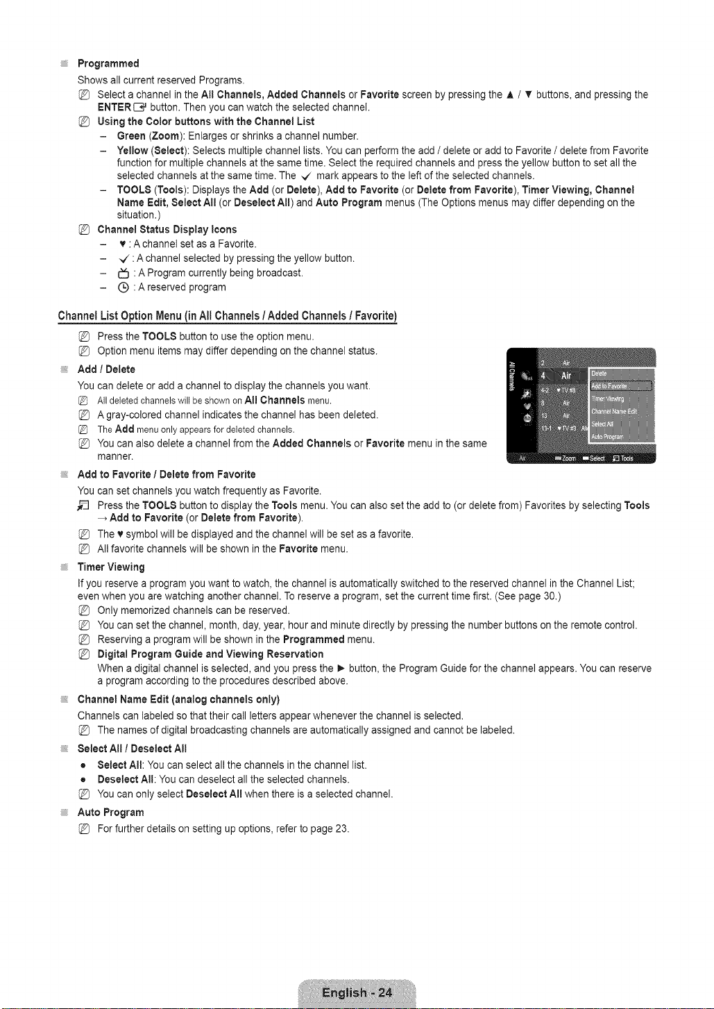
Channel List Option Menu (in All Channels /Added Channels / Favorite)
Press the TOOLS button to use the option menu.
Option menu items may differ depending on the channel status.
Add / Delete
You can delete or adda channel to display the channels you want.
AlldeletedchannelswillbeshownonA[! Channels menu.
Agray-colored channel indicates the channel has been deleted.
TheAdd menuonlyappearsfordeletedchannels.
You can also delete a channel from the Added Channels or Favorite menu in the same
manner.
Add to Favorite I Delete from Favorite
You can set channels you watch frequently as Favorite.
_3 Press the TOOLS button to display the Tools menu. You can also set the add to (ordelete from) Favorites by selecting Tools
Add to Favorite (or Delete from Favorite),
The v symbol will be displayed and the channel will be set as a favorite.
All favorite channels will be shown in the Favorite menu.
Timer Viewing
If you reserve a program you want to watch, the channel is automatically switched to the reserved channel inthe Channel List;
even when you are watching another channel. To reserve a program, set the current time first. (See page 30.)
Only memorized channels can be reserved.
You can set the channel, month, day, year, hour and minute directly by pressing the number buttons on the remote control.
Reserving a program will be shown in the Programmed menu.
Digital Program Guide and Viewing Reservation
When a digital channel is selected, and you press the _ button, the Program Guide for the channel appears. You can reserve
a program according to the procedures described above.
Channel Name Edit (analog channels only)
Channels can labeled so that their call letters appear whenever the channel is selected.
The names of digital broadcasting channels are automatically assigned and cannot be labeled.
Select All I Deselect All
= Select All: You can select all the channels inthe channel list.
• Deselect All: Youcan deselect all the selected channels.
You can only select Deselect All when there is a selected channel.
Auto Program
@ Forfurther details on setting up options, refer to page 23.
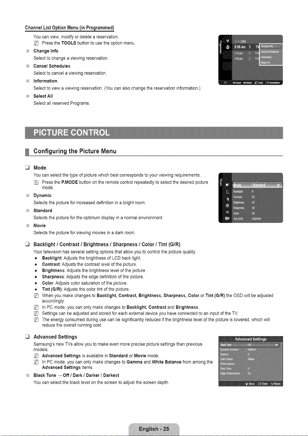
Channel List Option Menu (in Programmed)
You can view, modify or delete a reservation.
Press the TOOLS button to use the option menu.
Change Info
Select to change a viewing reservation.
Cancel Schedules
Select to cancel a viewing reservation.
information
Select to view a viewing reservation. (Youcan also change the reservation information.)
Select All
Select all reserved Programs.
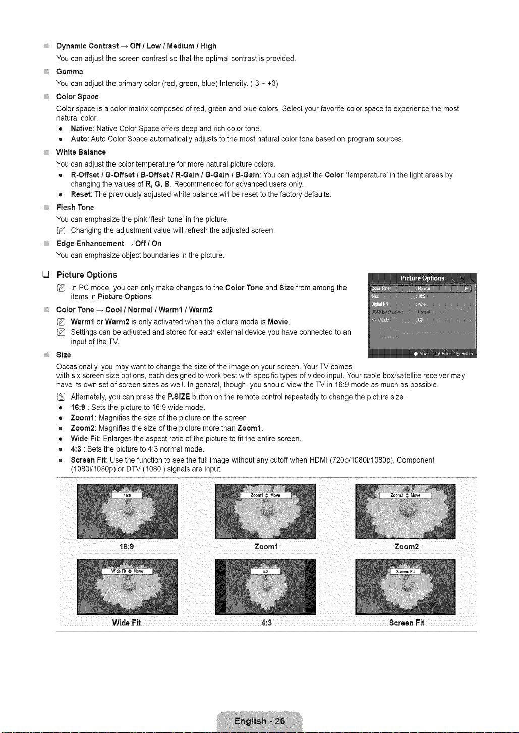
Configuring the Picture Menu
C)
Mode
You can select the type of picture which best corresponds to your viewing requirements.
Press the P.MODE button on the remote control repeatedly to select the desired picture
mode.
Dynamic
Selects the picture for increased definition in a bright room.
Standard
Selects the picture for the optimum display ina normal environment.
Movie
Selects the picture for viewing movies in a dark room.
C)
Backlight / Contrast / Brightness / Sharpness / Color / Tint (G/R)
Your television has several setting options that allow you to control the picture quality.
• Backlight: Adjusts the brightness of LCD back light.
• Contrast: Adjusts the contrast level of the picture.
• Brightness: Adjusts the brightness level of the picture
• Sharpness: Adjusts the edge definition of the picture.
• Color: Adjusts color saturation of the picture.
• Tint (G/R): Adjusts the color tint of the picture.
When you make changes to Backlight, Contrast, Brightness, Sharpness, Color or Tint (GIR) the OSD will be adjusted
accordingly.
In PC mode, you can only make changes to Backlight, Contrast and Brightness.
Settings can be adjusted and stored for each external device you have connected to an input of the TV.
The energy consumed during use can be significantly reduced if the brightness level of the picture islowered, which will
reduce the overall running cost.
C) Advanced Settings
Samsung's new TVs allow you to make even more precise picture settings than previous
models.
Advanced Settings is available in Standard or Movie mode.
In PC mode, you can only make changes to Gamma andWhite Balance from among the
Advanced Settings items.
Black Tone -, Off I Dark / Darker / Darkest
You can select the black level on the screen to adjust the screen depth.
Dynamic Contrast _ Off / Low / Medium I High
You can adjust the screen contrast so that the optimal contrast is provided.
Gamma
You can adjust the primary color (red, green, blue) Intensity. (-3 ~ +3)
Color Space
Color space is a color matrix composed of red, green and blue colors. Selectyour favorite color space to experience the most
natural color.
• Native: Native Color Space offers deep and rich color tone.
• Auto: Auto Color Space automatically adjusts to the most natural color tone based on program sources.
White Balance
You can adjust the color temperature for more natural picture colors.
• R=Offset / G=Offset/ B-Offset I R-Gain 1G-Gain / B=Gain: You can adjust the Color 'temperature' in the light areas by
changing the values of R, G, B. Recommended for advanced users only.
• Reset: The previously adjusted white balance will be resetto the factory defaults.
Flesh Tone
You can emphasize the pink 'flesh tone' in the picture.
Changing the adjustment value will refresh the adjusted screen.
Edge Enhancement _ Off / On
You can emphasize object boundaries in the picture.
C)
Picture Options
In PC mode, you can only make changes to the Color Tone and Size from among the
items in Picture Options.
Color Tone _ Cool / Normal / Warm1 / Warm2
Warm1 or Warm2 is only activated when the picture mode is Movie.
@ Settings can beadjusted and stored for each external device you have connected to an
input of the TV.
Size
Occasionally, you may want to change the size of the image on your screen. Your TV comes
with sixscreen size options, each designed to work best with specific types of video input. Your cable box/satellite receiver may
have its own set of screen sizes as well. Ingeneral, though, you should view the TV in 16:9 mode as much as possible.
(_ Alternately, you can press the P.SIZE button on the remote control repeatedly to change the picture size.
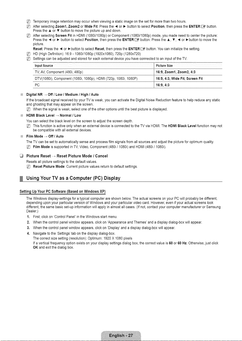
• 16:9 :Sets the picture to 16:9 wide mode.
• Zoom1: Magnifies the size of the picture onthe screen.
• Zoom2: Magnifies the size of the picture more than Zoom1.
• Wide Fit: Enlarges the aspect ratioof the picture to fit the entire screen.
• 4:3 :Sets the picture to 4:3 normal mode.
• Screen Fit: Use the function to seethe full image without any cutoff when HDMI (720p/1080i/1080p), Component
(1080i/I080p) or DTV (I080i) signals are input.
16:9 Zoom1 Zoom2
Wide Fit 4:3 Screen Fit
Temporaryimageretentionmayoccurwhenviewingastaticimageonthesetformorethantwohours.
AfterselectingZoom1, Zoom2 or Wide Fit: Press the 4 or _ button to select Position, then press the ENTER _ button.
Press the A or T button to move the picture up and down.
After selecting Screen Fit in HDMI (I080i/1080p) or Component (1080i/1080p) mode, you madeneed to center the picture:
Press the _ or _ button to select Position, then press the ENTER_ button. Press the A, T, 4 or l_button to move the
picture.
Reset: Press the _ or I_ button to select Reset, then press the ENTERI:B_button.You can initialize the setting.
HD (High Definition): 16:9 - 1080i/1080p (1920xi080), 720p (1280x720)
Settings can be adjusted and stored for each external device you have connected to an input of the TV.
input Source PictureSize
TV,AV, Component (480i, 480p) 16:9, Zoom1, Zoom2, 4:3
DTV(1O80i), Component (1080i, 108Op), HDMI (720p, 1080i, 1O80P) 16:9, 4:3, Wide Fit, Screen Fit
PC 16:9, 4:3
, Digital NR -_ Off / Low / Medium I High / Auto
If the broadcast signal received by your TV is weak, you can activate the Digital Noise Reduction feature to help reduce any static
and ghosting that may appear on the screen.
When the signal isweak, select one of the other options until the best picture is displayed.
HDMI Black Level _ Normal / Low
You can select the black level on the screen to adjust the screen depth.
This function is active only when an external device is connected to the TV via HDMI. The HDMI Black Level function may not
be compatible with all external devices.
Film Mode _ Off / Auto
The TV can be set to automatically sense and process film signals from all sources and adjust the picture for optimum quality.
Film Mode is supported in TV,Video, Component (480i/I080i) and HDMI (480i/ I080i).
C3
Picture Reset -_ Reset Picture Mode / Cancel
Resets all picture settings to the default values.
Reset Picture Mode: Current picture values return to default settings.
Using Your TV as a Computer (PC) Display
Setting Up Your PC Software (Based on Windows XP)
The Windows display-settings for a typical computer are shown below. The actual screens on your PC will probably be different,
depending upon your particular version of Windows and your particular video card. However,even if your actual screens look
different, the same basic set-up information will apply inalmost all cases. (If not, contact your computer manufacturer or Samsung
Dealer.)
1. First, click on 'Control Panel' in the Windows start menu.
2. Whenthe control panel window appears, click on 'Appearance and Themes' and a display dialog-box will appear.
3. Whenthe control panel window appears, click on 'Display' anda display dialog-box will appear.
4. Navigate to the 'Settings' tab on the display dialog-box.
The correct size setting (resolution): Optimum: 1920 X 1080 pixels
If a vertical frequency option exists on your display settings dialog box,the correct value is 60 or 60 Hz. Otherwise, just click
OK and exit the dialog box.
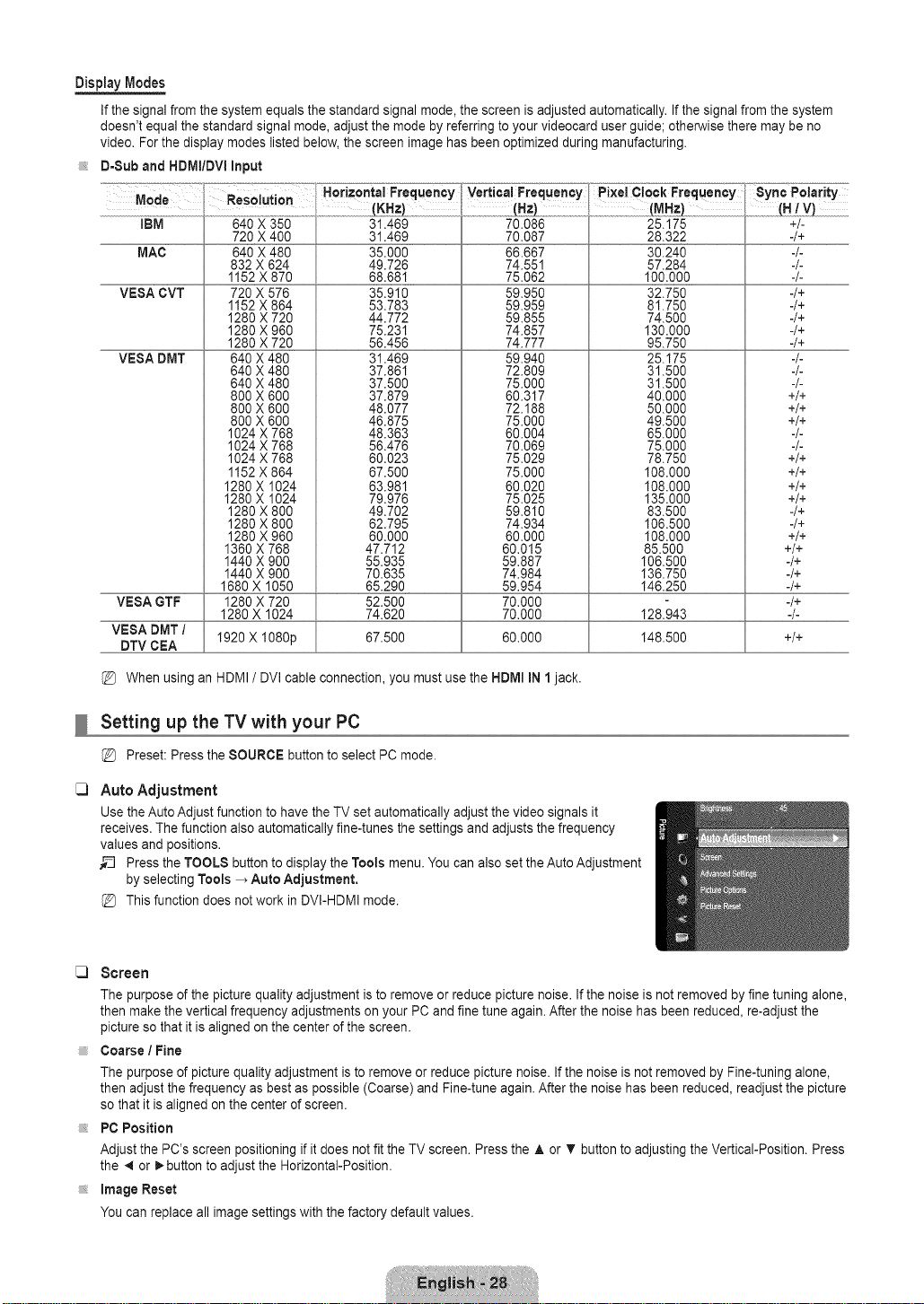
DisplayModes
If the signal from the system equals the standard signal mode, the screen is adjusted automatically. If the signal from the system
doesn't equal the standard signal mode, adjust the mode by referring to your videocard user guide; otherwise there may be no
video. For the display modes listed below, the screen image has been optimized during manufacturing.
D-Sub and HDMt/DVI Input
Vertica!Frequency P!xeiClock Frequency 8yn ¢ Polarity
IBM
MAC
VESA CVT
VESA DMT
VESA GTF
VESA DMT /
DTV CEA
640 X 350
720 X 400
640 X 480
832 X 624
1152X 870
720 X 576
1152X 864
1280 X 720
1280 X 960
1280 X 720
640 X 480
640 X 480
640 X 480
800 X 600
800 X 600
800 X 600
1024 X 768
1024 X 768
1024 X 768
1152X 864
1280X 1024
1280X 1024
1280 X 800
1280 X 800
1280 X 960
1360X 768
1440X 900
1440X 900
1680X 1050
1280X 720
1280X 1024
31.469
31.469
35.000
49.726
68.681
35.910
53.783
44.772
75.231
56.456
31.469
37.861
37.500
37.879
48.077
46.875
48.363
56.476
60.023
67.500
63.981
79.976
49.702
62.795
60.000
47.712
55.935
70.635
65.290
52.500
74.620
70.086
70.087
66.667
74.551
75.062
59.950
59.959
59.855
74.857
74.777
59.940
72.809
75.000
60.317
72.188
75.000
60.004
70.069
75.029
75.000
60.020
75.025
59.810
74.934
60.000
60.015
59.887
74.984
59.954
70.000
70.000
1920X I080p 67.500 60.000 148.500 +/+
When using an HDMI / DVI cable connection, you must use the HDIVllIN 1jack.
(M_z} .........
25.175
28.322
30.240
57.284
I00.000
32.750
81.750
74.500
130.000
95.750
25.175
31.500
31.500
40.000
50.000
49.500
65.000
75.000
78.750
108.000
108.000
135.000
83.500
106.500
108.000
85.500
106.500
136.750
146.250
128.943
+/-
-/+
-/-
-/+
-/+
-/+
-/+
-/+
=/=
=/=
=/=
+/+
+/+
+/+
=/=
=/=
+/+
+/+
+/+
+/+
-/+
-/+
+/+
+/+
-/+
-/+
-/+
-/+
-/=
Setting up the TV with your PC
Preset: Press the SOURCE button to select PC mode.
_3
Auto Adjustment
Use the Auto Adjust function to have the TV set automatically adjust the video signals it
receives. The function also automatically fine-tunes the settings and adjusts the frequency
values and positions.
_-_ Press the TOOLS button to display the Tools menu. You can also set the Auto Adjustment
by selecting Tools _ Auto Adjustment.
This function does not work in DVI-HDMI mode.
Screen
The purpose of the picture quality adjustment is to remove or reduce picture noise. If the noise is not removed by fine tuning alone,
then make the vertical frequency adjustments on your PC and fine tune again. After the noise has been reduced, re-adjust the
picture so that it is aligned on the center of the screen.
, Coarse / Fine
The purpose of picture quality adjustment is to remove or reduce picture noise. If the noise is not removed by Fine-tuning alone,
then adjust the frequency as best as possible (Coarse) and Fine-tune again. After the noise has been reduced, readjust the picture
so that it is aligned on the center of screen.
PC Position
Adjust the PC's screen positioning if it does not fit the TV screen. Press the ,& or T button to adjusting the Vertical-Position. Press
the 41or _.button to adjust the Horizontal-Position.
Image Reset
You can replace all image settings with the factory default values.
 Loading...