

Page 1
Contact SAMSUNG WORLDWIDE
If you have any questions or comments relating to Samsung products, please contact the SAMSUNG
customer care center.
Comment contacter Samsung dans le monde
Si vous avez des suggestions ou des questions concernant les produits Samsung, veuillez contacter le Service
Consommateurs Samsung.
Country
CANADA 1-800-SAMSUNG(726-7864) www.samsung.com/ca
U.S.A 1-800-SAMSUNG(726-7864) www.samsung.com
Customer Care Center
Web Site Address
Samsung Electronics Canada Inc., Customer
Service 55 Standish Court Mississauga,
Ontario L5R 4B2 Canada
Samsung Electronique Canada Inc.,
Service à la Clientèle 55 Standish Court
Mississauga, Ontario L5R 4B2 Canada
Samsung Electronics America, Inc.
105 Challenger Road
Ridgefield Park, NJ 07660-0511
LCD TV
user manual
BN68-01395C-00
imagine the possibilities
Thank you for purchasing a Samsung product.
To receive a more complete service, please
register your product at
www.samsung.com/global/register
Model Serial No.
Page 2
Important Warranty Information Regarding Television Format Viewing
Wide screen format LCD Displays (16:9, the aspect ratio of the screen width to height) are primarily designed to view wide screen format
full-motion video. The images displayed on them should primarily be in the wide screen 16:9 ratio format, or expanded to fill the screen
if your model offers this feature and the images are constantly moving. Displaying stationary graphics and images on screen, such as
the dark side-bars on nonexpanded standard format television video and programming, should be limited to no more than 5% of the total
television viewing per week.
Additionally, viewing other stationary images and text such as stock market reports, video game displays, station logos, web sites or
computer graphics and patterns, should be limited as described above for all televisions. Displaying stationary images that exceed the
above guidelines can cause uneven aging of LCD Displays that leave subtle, but permanent burned-in ghost images in the LCD picture. To
avoid this, vary the programming and images, and primarily display full screen moving images, not stationary patterns or dark bars.
On LCD models that offer picture sizing features, use these controls to view different formats as a full screen picture.
Be careful in the selection and duration of television formats used for viewing. Uneven LCD aging as a result of format selection and use,
as well as burned-in images, are not covered by your Samsung limited warranty.
U.S.A Only
The product unit accompanying this user manual is licensed under certain intellectual property rights of certain third parties. In particular,
this product is licensed under the following US patents: 5,991,715, 5,740,317, 4,972,484, 5,214,678, 5,323,396, 5,539,829, 5,606,618,
5,530,655, 5,777,992, 6,289,308, 5,610,985, 5,481,643, 5,544,247, 5,960,037, 6,023,490, 5,878,080, and under US Published Patent
Application No. 2001-44713-A1.
This license is limited to private non-commercial use by end-user consumers for licensed contents. No rights are granted for commercial
use. The license does not cover any product unit other than this product unit and the license does not extend to any unlicensed product
unit or process conforming to ISO/IEC 11172-3 or ISO/IEC 13818-3 used or sold in combination with this product unit. The license only
covers the use of this product unit to encode and/or decode audio files conforming to the ISO/IEC 11172-3 or ISO/IEC 13818-3. No rights
are granted under this license for product features or functions that do not conform to the ISO/IEC 11172-3 or ISO/IEC 13818-3.
Other countries
The product unit accompanying this user manual is licensed under certain intellectual property rights of certain third parties. This license is
limited to private non-commercial use by end-user consumers for licensed contents. No rights are granted for commercial use. The license
does not cover any product unit other than this product unit and the license does not extend to any unlicensed product unit or process
conforming to ISO/IEC 11172-3 or ISO/IEC 13818-3 used or sold in combination with this product unit. The license only covers the use of
this product unit to encode and/or decode audio files conforming to the ISO/IEC 11172-3 or ISO/IEC 13818-3. No rights are granted under
this license for product features or functions that do not conform to the ISO/IEC 11172-3 or ISO/IEC 13818-3.
SAMSUNG ELECTRONICS NORTH AMERICAN LIMITED WARRANTY STATEMENT
Subject to the requirements, conditions, exclusions and limitations of the original Limited Warranty supplied with Samsung Electronics
(SAMSUNG) products, and the requirements, conditions, exclusions and limitations contained herein, SAMSUNG will additionally provide
Warranty Repair Service in the United States on SAMSUNG products purchased in Canada, and in Canada on SAMSUNG products purchased
in the United States, for the warranty period originally specified, and to the Original Purchaser only.
The above described warranty repairs must be performed by a SAMSUNG Authorized Service Center. Along with this Statement, the Original
Limited Warranty Statement and a dated Bill of Sale as Proof of Purchase must be presented to the Service Center. Transportation to and from
the Service Center is the responsibility of the purchaser.
Conditions covered are limited only to manufacturing defects in material or workmanship, and only those encountered in normal use of the
product.
Excluded, but not limited to, are any originally specified provisions for, in-home or on-site services, minimum or maximum repair times,
exchanges or replacements, accessories, options, upgrades, or consumables.
For the location of a SAMSUNG Authorized Service Center, please call toll-free:
In the United States : 1-800-SAMSUNG (1-800-726-7864) In Canada : 1-800-SAMSUNG
See the warranty card for more information on warranty terms.
➣
Precautions When Displaying a Still Image
A still image may cause permanent damage to the TV screen
• Do not display a still image on the LCD panel for more than 2 hours as it can cause screen image retention. This image retention is also
known as "screen burn". To avoid such image retention, reduce the degree of brightness and contrast of the screen when displaying a still
image.
• Watching the LCD TV in 4:3 format for a long period of time may leave traces of borders displayed on the left, right and
• Displaying still images from Video games and PC for longer than a certain period of time may produce partial after-images.
To prevent this effect, reduce the ‘brightness’ and ‘contrast’ when displaying still images.
© 2008 Samsung Electronics Co., Ltd. All rights reserved.
center of the screen caused by the difference of light emission on the screen.
Playing a DVD or a game console may cause a similar effect to the screen.
Damages caused by the above effect are not covered by the Warranty.
Page 3

Contents
English
GENERAL INFORMATION
List of Features ............................................................................. 2
■
Accessories
■
■
Viewing the Control Panel
■
Viewing the Connection Panel
■
Remote Control
■
Installing Batteries in the Remote Control
CONNECTIONS
■
Connecting VHF and UHF Antennas ............................................7
■
Connecting Cable TV
■
Connecting a DVD Player or Cable Box/Satellite receiver
(Set-Top Box) via HDMI ................................................................9
■
Connecting a DVD Player or Cable Box/Satellite receiver
(Set-Top Box) via DVI ...................................................................9
■
Connecting a DVD Player or Cable Box/Satellite receiver
(Set-Top Box) via Component cables ......................................... 10
■
Connecting a Camcorder
■
Connecting a VCR
■
Connecting a Digital Audio System
■
Connecting an Amplier/DVD Home Theater
■
Connecting a PC
CONNECTIONS
■
Connecting VHF and UHF Antennas ..........................................14
■
Connecting Cable TV
■
Connecting a DVD Player or Cable Box/Satellite receiver
(Set-Top Box) via HDMI ..............................................................16
■
Connecting a DVD Player or Cable Box/Satellite receiver
(Set-Top Box) via DVI .................................................................16
■
Connecting a DVD Player or Cable Box/Satellite receiver
(Set-Top Box) via Component cables ......................................... 17
■
Connecting a Camcorder
■
Connecting a VCR
■
Connecting a Digital Audio System
■
Connecting an Amplier/DVD Home Theater
■
Connecting a PC
..................................................................................2
...........................................................3
....................................................4
............................................................................ 6
....................................7
(LN26A450C1D, LN40A450C1D)
................................................................... 8
..........................................................10
...................................................................... 11
............................................ 12
............................. 12
........................................................................ 13
(LN32A450C1D, LN37A450C1D)
................................................................. 15
..........................................................17
...................................................................... 18
............................................ 19
............................. 19
........................................................................ 20
OPERATION
■
Turning the TV On and Off .........................................................21
■
Plug & Play Feature
■
Changing Channels
■
Adjusting the Volume
■
Viewing the Display
■
Viewing the Menus
■
Using the TOOLS Button
■
Memorizing the Channels
■
To Select the Source
■
To Edit the Input Source Name
...................................................................21
.................................................................... 22
.................................................................. 23
....................................................................23
.....................................................................23
............................................................ 24
........................................................... 24
.................................................................. 26
..................................................26
PICTURE CONTROL
■
Changing the Picture Standard .................................................. 27
■
Customizing the Picture Settings
■
Adjusting the Detailed Settings
■
Conguring Picture Options
■
Resetting the Picture Settings to the Factory Defaults
...............................................27
..................................................28
.......................................................31
............... 34
CHANNEL CONTROL
Clearing Scrambled Channels - Digital ......................................39
■
Adding and Erasing Channels
■
■
To Set-Up Your Favorite Channels
■
Using the Channel Lists - Analog
■
Viewing the Channel Lists
■
Labeling Channels
■
Fine Tuning Analog Channels
■
Checking the Digital-Signal Strength
...................................................................... 43
.................................................... 40
.............................................41
............................................... 42
..........................................................42
....................................................44
.......................................... 44
PC DISPLAY
■
Using Your TV as a Computer (PC) Display ............................... 45
■
Display Modes
■
Setting up the TV with your PC
............................................................................ 45
.................................................. 46
TIME SETTING
■
Setting the Clock ........................................................................ 48
FUNCTION DESCRIPTION
■
Selecting a Menu Language ....................................................... 51
■
Using the V-Chip
■
Viewing Closed Captions (On-Screen Text Messages)
- Analog ......................................................................................59
■
Viewing Closed Captions (On-Screen Text Messages)
- Digital .......................................................................................60
■
Adjusting the TV On/Off Melody Sound......................................61
■
Setting the Entertainment mode
■
Using the Energy Saving Feature
■
Upgrading the Software
........................................................................52
................................................. 61
..............................................62
.............................................................. 62
ABOUT ANYNET+
■
What is Anynet+? .......................................................................63
■
Connecting Anynet
■
Setting Up Anynet
■
Scanning and Switching between Anynet
■
Recording
■
Listening through a Receiver (Home theater)
■
Troubleshooting for Anynet
+
Devices ......................................................63
+
.....................................................................64
...................................................................................65
+
.......................................................66
+
Devices ...................64
............................66
APPENDIX
■
Troubleshooting .......................................................................... 67
■
Installing the Stand
■
Disconnecting the Stand
■
Auto Wall-Mount Adjustment (Sold separately)
(LN32A450C1D, LN37A450C1D, LN40A450C1D) ..................70
■
Wall Mount Kit Specications (VESA)
■
Using the Anti-Theft Kensington Lock
■
Specications
■
Dimensions
..................................................................... 69
............................................................69
........................................71
........................................ 72
............................................................................. 73
................................................................................. 74
SOUND CONTROL
■
Changing the Sound Standard ...................................................35
■
Customizing the Sound
■
Setting the TruSurround XT
■
Choosing a Multi-Channel Sound (MTS) track - Digital
■
Choosing a Multi-Channel Sound (MTS) track - Analog
■
Automatic Volume Control
■
Setting the TV Speakers On/Off
■
Connecting Headphones (Sold separately)
.............................................................. 35
........................................................ 36
.......................................................... 37
.................................................38
................................ 38
............. 36
............ 37
Symbol Press Note One-Touch
Button
English - 1
Page 4
General Information
List of Features
Adjustable picture settings that can be stored in the TV’s memory.
Automatic timer to turn the TV on and off.
A special sleep timer.
Excellent Digital Interface & Networking :
With a built-in HD digital tuner, non-subscription HD broadcasts can be viewed with no Cable Box/Satellite receiver
(Set-Top Box) needed.
HDMI/DVI connection of your PC to this TV.
Excellent Picture Quality
- DNIe technology provides life-like clear images.
SRS TruSurround XT
- SRS TruSurround XT provides a virtual surround system.
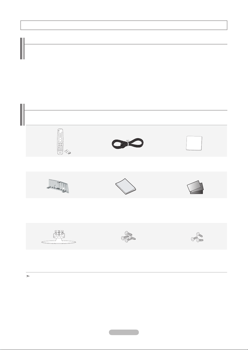
Accessories
Please make sure the following items are included with your LCD TV.
If any items are missing, contact your dealer.
Remote Control & Batteries (AAA x 2)
(BN59-00687A)
Cover-Bottom
(LN26A450C1D: BN63-04269A)
(LN32A450C1D: BN63-04269A)
(LN37A450C1D: BN63-04243A)
(LN40A450C1D: BN63-04243A)
Stand
(LN26A450C1D: BN96-06463E)
(LN32A450C1D: BN96-06464A)
(LN37A450C1D: BN96-07182A)
(LN40A450C1D: BN96-07182A)
The items color and shape may vary depending on the model.
Power Cord
(3903-000144)
Owner’s Instructions
Stand Screw (M4 X L16)
(6002-001294)
Cleaning Cloth
(BN63-01798A)
Warranty Card / Registration Card /
Safety Guide Manual
(Not available in all locations)
Stand Screw (M4 X L14)
(LN32A450C1D : 6003-001334)
(LN37A450C1D : 6003-001334)
(LN40A450C1D : 6003-001334)
English - 2
Page 5
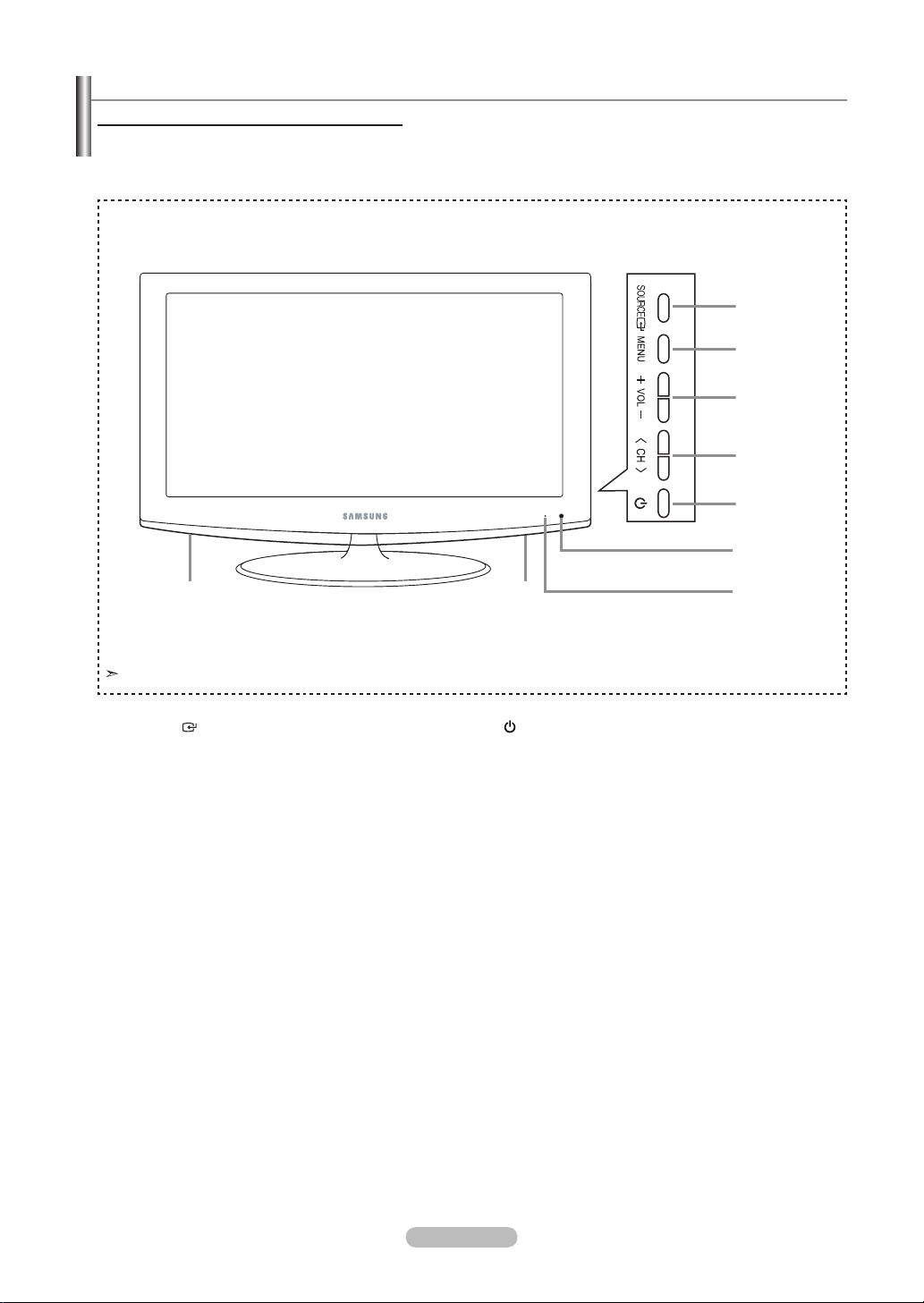
Viewing the Control Panel
Buttons on the Lower-Right Part of the Panel
The buttons on the lower-right panel control your TV’s basic features, including the on-screen menu.
To use the more advanced features, you must use the remote control.
Side Panel buttons
1
2
3
4
5
6
The product color and shape may vary depending on the model.
1
SOURCE
Toggles between all the available input sources
(TV, AV1, AV2, S-Video, Component1, Component2,
PC, HDMI1, HDMI2, HDMI3).
In the on-screen menu, use this button as you would
use the ENTER button on the remote control.
2
MENU
Press to see an on-screen menu of your TV’s features.
3
+ VOL -
Press to increase or decrease the volume.
In the on-screen menu, use the + VOL - buttons as you
would use the ◄ and ► buttons on the remote control.
4 < CH >
Press to change channels.
In the on-screen menu, use the < CH
would use the ▼ and ▲ buttons on the remote control.
>
buttons as you
88
5
(POWER)
Press to turn the TV on and off.
6
REMOTE CONTROL SENSOR
Aim the remote control towards this spot on the TV.
7
POWER INDICATOR
Blinks and turns off when the power is on and
lights up in stand-by mode.
8
SPEAKERS
7
English - 3
Page 6
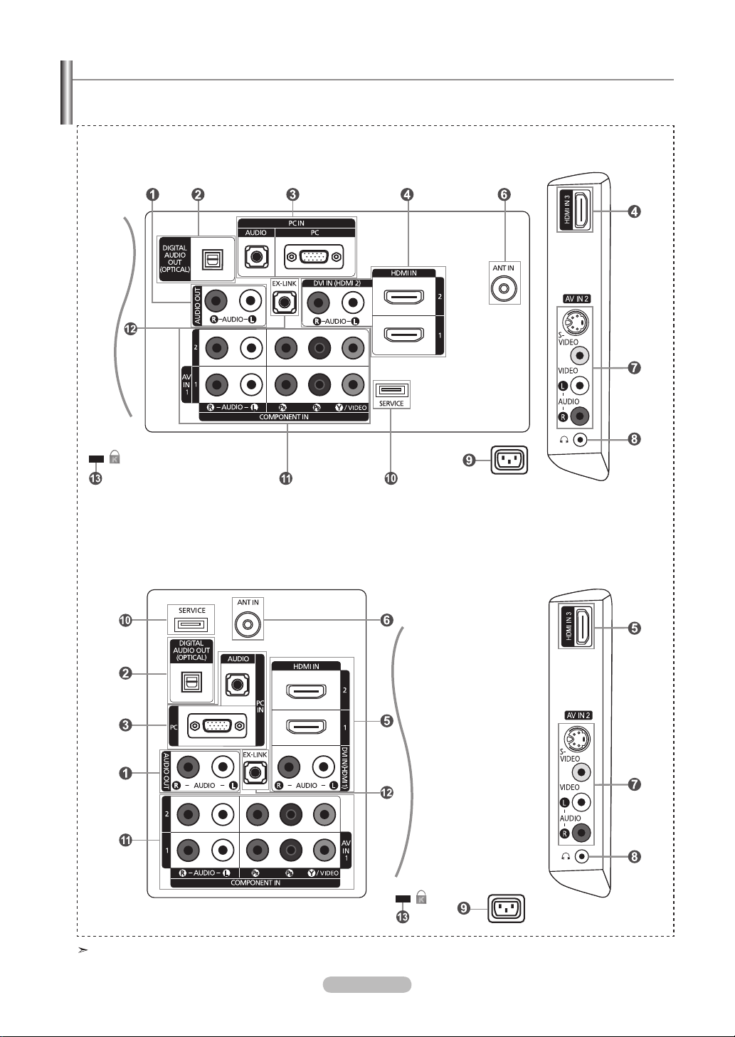
Viewing the Connection Panel
Use the connection panel jacks to connect A/V components that will be connected continuously, such as DVD players or a VCR.
For more information on connecting equipment, see pages 7~20.
LN26A450C1D, LN40A450C1D
[TV Side Panel]
[TV Rear Panel]
LN32A450C1D, LN37A450C1D
[TV Rear Panel]
The product color and shape may vary depending on the model.
[TV Side Panel]
English - 4
Page 7

1
AUDIO OUT
Connects to the audio input jacks on your Amplifier/Home theater.
2 DIGITAL AUDIO OUT (OPTICAL)
Connects to a Digital Audio component.
3 PC IN [PC] / [AUDIO]
Connects to the video and audio output jacks on your PC.
4
HDMI IN 1, 2, 3 / DVI IN(HDMI2)[R-AUDIO-L] (LN26A450C1D, LN40A450C1D)LN26A450C1D, LN40A450C1D)
Connects to the HDMI jack of a device with an HDMI output.
Use the HDMI IN 2 jack for DVI connection to an external device.
Use a DVI to HDMI cable or DVI-HDMI adapter (DVI to HDMI) for video connection and the
DVI IN (HDMI2) [R-AUDIO-L] jacks for audio.
- No sound connection is needed for an HDMI to HDMI connection.
- When using an HDMI/DVI cable connection, you must use the HDMI IN 2 jack.
5 HDMI IN 1, 2, 3 / DVI IN(HDMI1)[R-AUDIO-L] (LN32A450C1D, LN37A450C1D)LN32A450C1D, LN37A450C1D)
Connects to the HDMI jack of a device with an HDMI output.
Use the HDMI IN 1 jack for DVI connection to an external device.
Use a DVI to HDMI cable or DVI-HDMI adapter (DVI to HDMI) for video connection and the
DVI IN (HDMI1) [R-AUDIO-L] jacks for audio.
- No sound connection is needed for an HDMI to HDMI connection.
- When using an HDMI/DVI cable connection, you must use the HDMI IN 1 jack.
6 ANT IN
Connects to an antenna or cable TV system.
7 AV IN 2
Video and audio inputs for external devices, such as a camcorder or VCR.
S-VIDEO
Connects an S-Video signal from a camcorder or VCR.
8
(HEADPHONE)
Connects a set of external headphones for private listening.
9
POWER INPUT
Connects the supplied power cord.
0
SERVICE
Connector for SERVICE only.
! COMPONENT IN 1, 2
The COMPONENT IN 1 jack is also used as the AV IN 1 jack.
- Connect the video cable to the COMPONENT IN 1 [Y/VIDEO] jack and the audio cable to the
COMPONENT IN 1 [R-AUDIO-L] jacks.
@ EX-LINK
- LN26A450C1D
Connector for SERVICE only.
- LN32A450C1D / LN37A450C1D / LN40A450C1D
Connect this to the jack on the optional wall mount bracket. This will allow you to adjust the TV viewing angle using
your remote control.
#
KENSINGTON LOCK
The Kensington Lock (optional) is a device used to physically fix the system when used in a public place.
If you want to use a locking device, contact the dealer where you purchased the TV.
The location of the Kensington Lock may be different depending on its model.
English - 5
Page 8
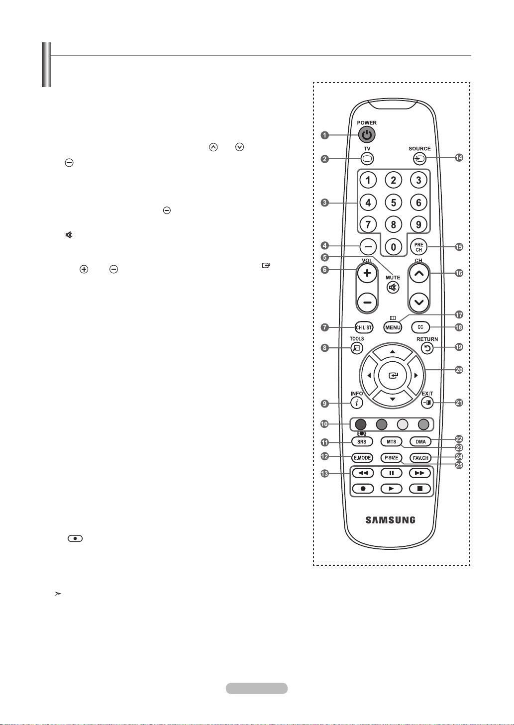
Remote Control
You can use the remote control up to a distance of about 23 feet from the TV.
1
POWER
Turns the TV on and off.
2
TV
Selects the TV mode directly.
3
NUMERIC BUTTONS
Press to change the channel.
4
Press to select additional
channels(digital and analog) being
broadcast by the same station.
For example, to select channel
“54-3”, press “54”, then press “
and “3”.
5 (
MUTE)
Press to temporarily cut off the
sound.
6
VOL / VOL
Press to increase or decrease
the volume.
7
CH LIST
Used to display Channel Lists on
the screen.
8 TOOLS
Use to quickly select frequently
used functions.
9 INFO
Press to display information on
the TV screen.
0
COLOR BUTTONS
Use these buttons in the
Channel list, etc.
!
SRS
Selects SRS TruSurround XT
mode.
@
E.MODE
Press to select the preset
display and sound modes for
sports, cinema and games.
#
Use these buttons in the DMA and
Anynet+ modes.
: This remote can be used
(
to control recording on Samsung
recorders with the Anynet+
feature)
$
SOURCE
Press to display and select the
available video sources.
%
PRE CH
Tunes to the previous channel.
^ CH / CH
Press to change channels.
&
MENU
Displays the main on-screen
menu.
*
CC
”
Controls the caption decoder.
(
RETURN
Returns to the previous menu.
) UP▲ / DOWN▼ / LEFT◄
RIGHT►
Use to select on-screen menu
items and change menu values.
a EXIT
Press to exit the menu.
b
DMA (Digital Media Adapter)
Use this when connecting a
SAMSUNG DMA device through
an HDMI interface and switching
to DMA mode.
For more information on the
operating procedures, refer to
the user manual of the DMA.
This button is available when
“Anynet+(HDMI-CEC)” is “On”
(see page 64)
c MTS
Press to choose stereo, mono
or Separate Audio Program
(SAP broadcast).
d
FAV.CH
Press to switch to your favorite
channels.
e P.SIZE
Picture size selection.
/ ENTER
/
The performance of the remote control may be affected by bright light.
English - 6
Page 9
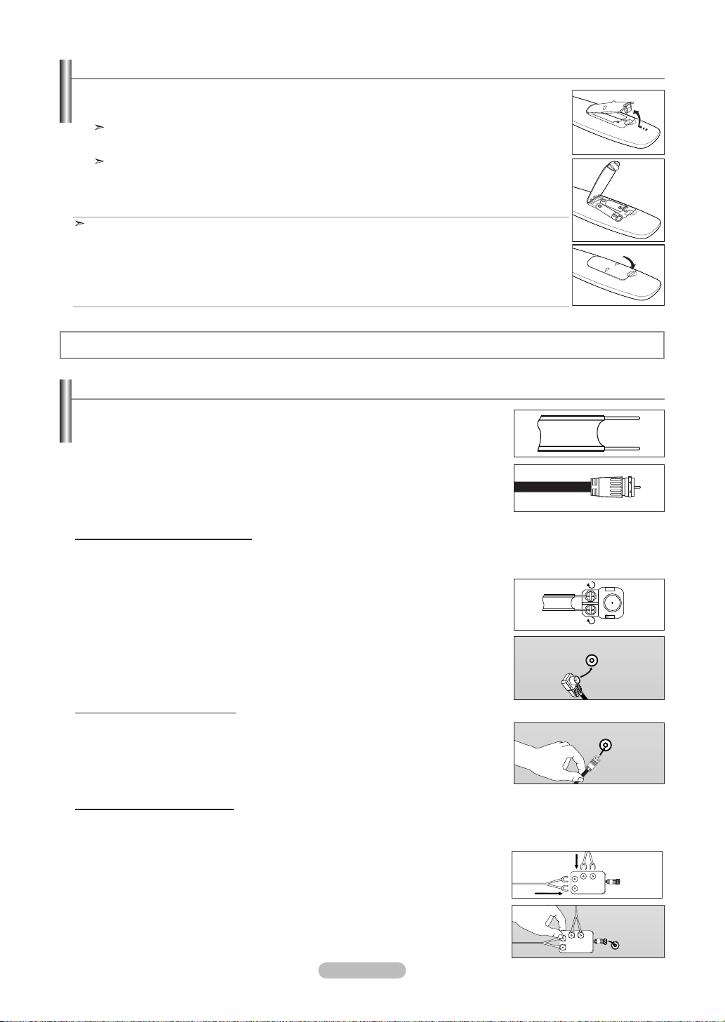
Installing Batteries in the Remote Control
1. Lift the cover at the back of the remote control upward as shown in the figure.
2. Install two AAA size batteries.
Make sure to match the "+" and "–" ends of the batteries with the diagram inside the compartment.
3. Replace the cover.
Remove the batteries and store them in a cool, dry place if you won’t be using the remote control for a
long time.
The remote control can be used up to about 23 feet from the TV.
(Assuming typical TV usage, the batteries should last for about one year.)
If the remote control doesn’t work, check the following:
1. Is the TV power on?
2. Are the plus and minus ends of the batteries reversed?
3. Are the batteries drained?
4. Is there a power outage or is the power cord unplugged?
5. Is there a special fluorescent light or neon sign nearby?
Connections (LN26A450C1D, LN40A450C1D)
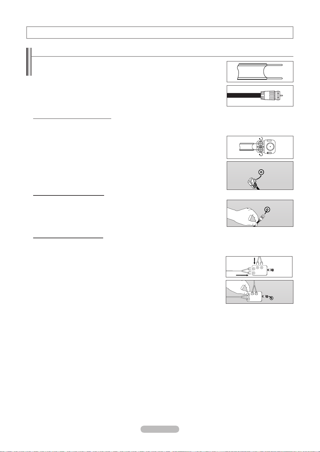
Connecting VHF and UHF Antennas
If your antenna has a set of leads that look like the diagram to the right, see "Antennas with
300 Ω Flat Twin Leads" below.
If your antenna has one lead that looks like the diagram to the right, see "Antennas with 75
Ω Round Leads".
If you have two antennas, see "Separate VHF and UHF Antennas".
Antennas with 300 Ω Flat Twin Leads
If you are using an off-air antenna (such as a roof antenna or "rabbit ears") that has 300 Ω twin at leads, follow the directions
below.
1. Place the wires from the twin leads under the screws on a 300-75 Ω adapter
(not supplied).
Use a screwdriver to tighten the screws.
2. Plug the adaptor into the ANT IN terminal on the back of the TV.
ANT IN
Antennas with 75 Ω Round Leads
1. Plug the antenna lead into the ANT IN terminal on the back of the TV.
ANT IN
Separate VHF and UHF Antennas
If you have two separate antennas for your TV (one VHF and one UHF), you must combine the two antenna signals before
connecting the antennas to the TV. This procedure requires an optional combiner-adaptor (available at most electronics shops).
1. Connect both antenna leads to the combiner.
UHF
VHF
2. Plug the combiner into the ANT IN terminal on the bottom of the rear panel.
English - 7
ANT IN
UHF
VHF
Page 10
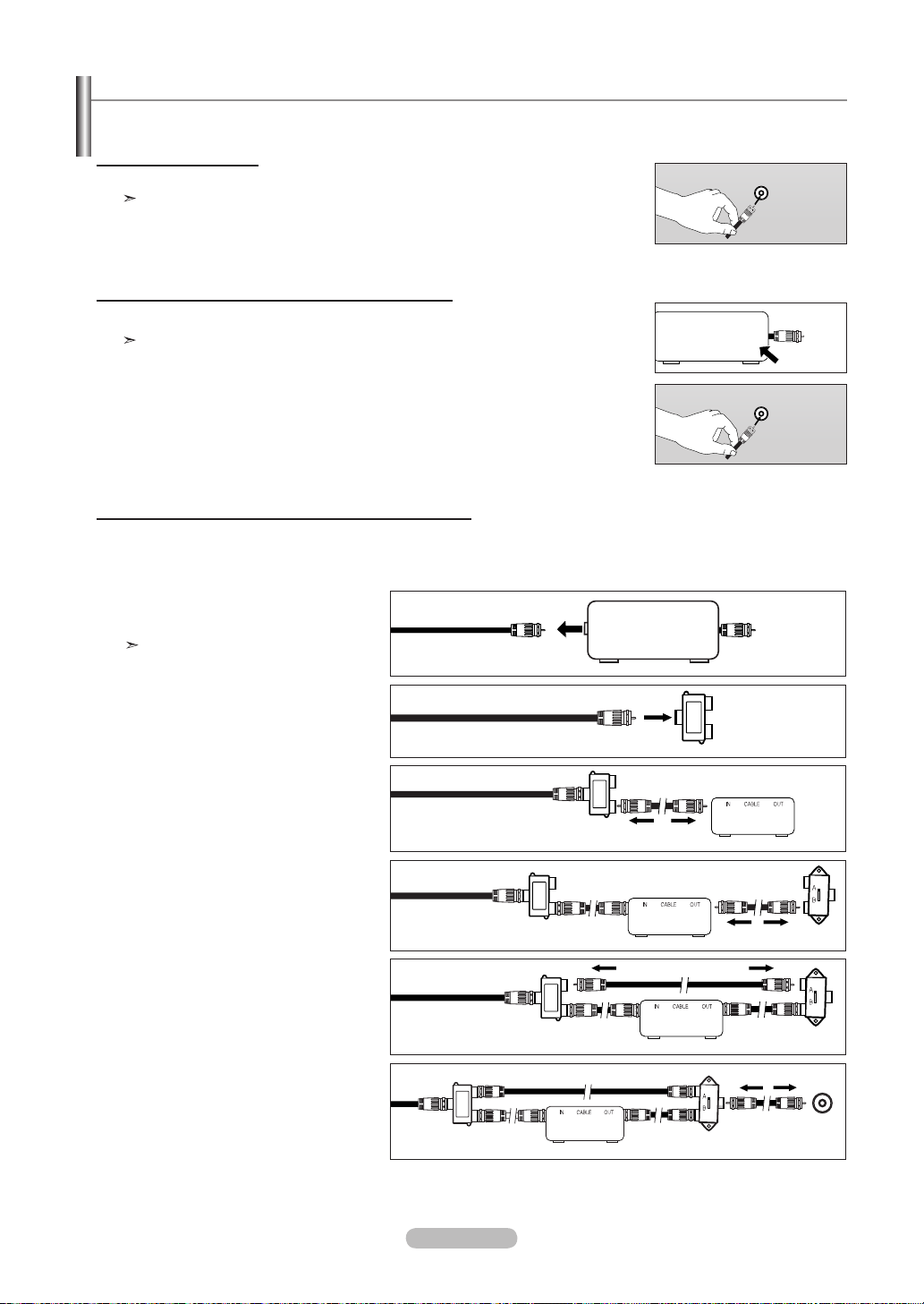
Connecting Cable TV
To connect to a cable TV system, follow the instructions below.
Cable without a Cable Box
1. Plug the incoming cable into the ANT IN terminal on the back of the TV.
Because this TV is cable-ready, you do not need a cable box to view unscrambled cable channels.
ANT IN
Connecting to a Cable Box that Descrambles All Channels
1. Find the cable that is connected to the ANT OUT terminal on your cable box.
This terminal might be labeled "ANT OUT", "VHF OUT" or simply, "OUT".
ANT IN
ANT OUT
2. Connect the other end of this cable to the ANT IN terminal on the back of the TV.
ANT IN
Connecting to a Cable Box that Descrambles Some Channels
If your cable box descrambles only some channels (such as premium channels), follow the instructions below. You will need a twoway splitter, an RF (A/B) switch and four lengths of RF cable. (These items are available at most electronics stores.)
Find and disconnect the cable that is
1.
connected to the ANT IN terminal on your
cable box.
This terminal might be labeled "ANT IN",
"VHF IN" or simply, "IN".
ANT IN
2. Connect this cable to a two-way splitter.
Incoming
3. Connect an RF cable between the
OUTPUT
terminal on the splitter and the IN terminal
on the cable box.
Incoming
cable
cable
Splitter
Splitter
Cable Box
4. Connect an RF cable between the
ANT OUT terminal on the cable box and
the B–IN terminal on the RF(A/B) switch.
Incoming
cable
Splitter
Cable Box
RF (A/B)
Switch
5. Connect another cable between the other
OUT terminal on the splitter and the A–IN
terminal on the RF (A/B) switch.
Incoming
cable
Splitter
Cable Box
RF (A/B)
Switch
6. Connect the last RF cable between the
OUT terminal on the RF (A/B) switch and
ANT IN
the ANT IN terminal on the rear of the TV.
Incoming
cable
Splitter
Cable Box
RF (A/B)
Switch
TV Rear
After you have made this connection, set the A/B switch to the "A" position for normal viewing. Set the A/B switch to the "B" position to
view scrambled channels. (When you set the A/B switch to "B", you will need to tune your TV to the cable box’s output channel, which is
usually channel 3 or 4.)
English - 8
Page 11
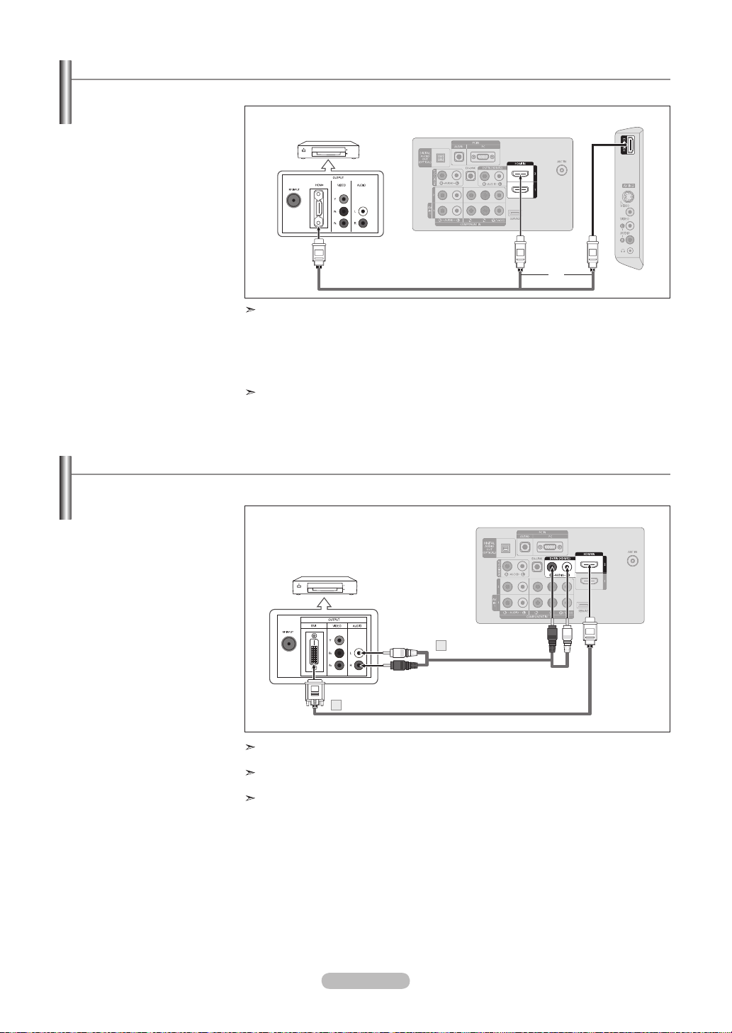
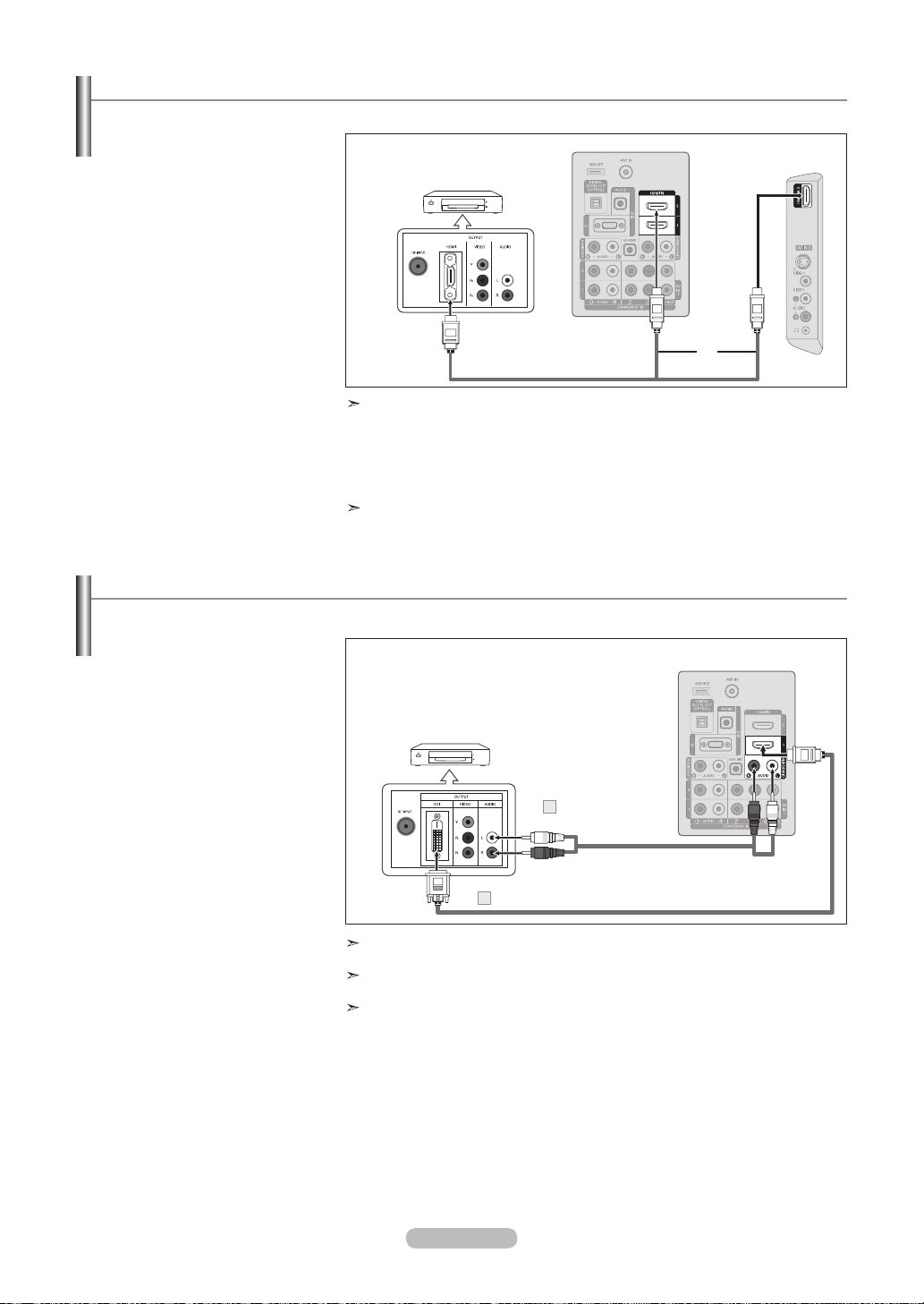
Connecting a DVD Player or Cable Box/Satellite receiver (Set-Top Box) via HDMI
This connection can only be made if there is an HDMI Output connector on the external device.
1. Connect an HDMI Cable
between the HDMI IN (1, 2
or 3) jack on the TV and the
HDMI jack on the DVD Player
or Cable Box/Satellite receiver
(Set-Top Box).
DVD Player or Cable Box/Satellite receiver
(Set-Top Box) Rear Panel
TV Rear Panel
TV Side Panel
What is HDMI?
HDMI Cable (Not supplied)
or
• HDMI(High-Definition Multimedia Interface), is an interface that enables the
transmission of digital audio and video signals using a single cable.
• The difference between HDMI and DVI is that the HDMI device is smaller in
size and has the HDCP (High Bandwidth Digital Copy Protection) coding feature
installed.
Each DVD Player or Cable Box/Satellite receiver (Set-Top Box) has a different back
panel configuration.
Connecting a DVD Player or Cable Box/Satellite receiver (Set-Top Box) via DVI
This connection can only be made if there is a DVI Output connector on the external device.
1. Connect a DVI to HDMI Cable
or DVI-HDMI Adapter between
the HDMI IN 2 jack on the TV
and the DVI jack on the DVD
Player or Cable Box/Satellite
receiver (Set-Top Box).
2. Connect Audio Cables
between the DVI IN (HDMI 2)
[R-AUDIO-L] jack on the TV
and the DVD Player or Cable
Box/Satellite receiver (Set-Top
Box).
DVD Player or Cable Box/
Satellite receiver (Set-Top Box)
Audio Cable
2
(Not supplied)
TV Rear Panel
DVI to HDMI Cable (Not supplied)1
Each DVD Player or Cable Box/Satellite receiver (Set-Top Box) has a different back
panel configuration.
When connecting a DVD Player or Cable Box/Satellite receiver (Set-Top Box), match
the color of the connection terminal to the cable.
When using an HDMI/DVI cable connection, you must use the HDMI IN 2 jack.
English - 9
Page 12
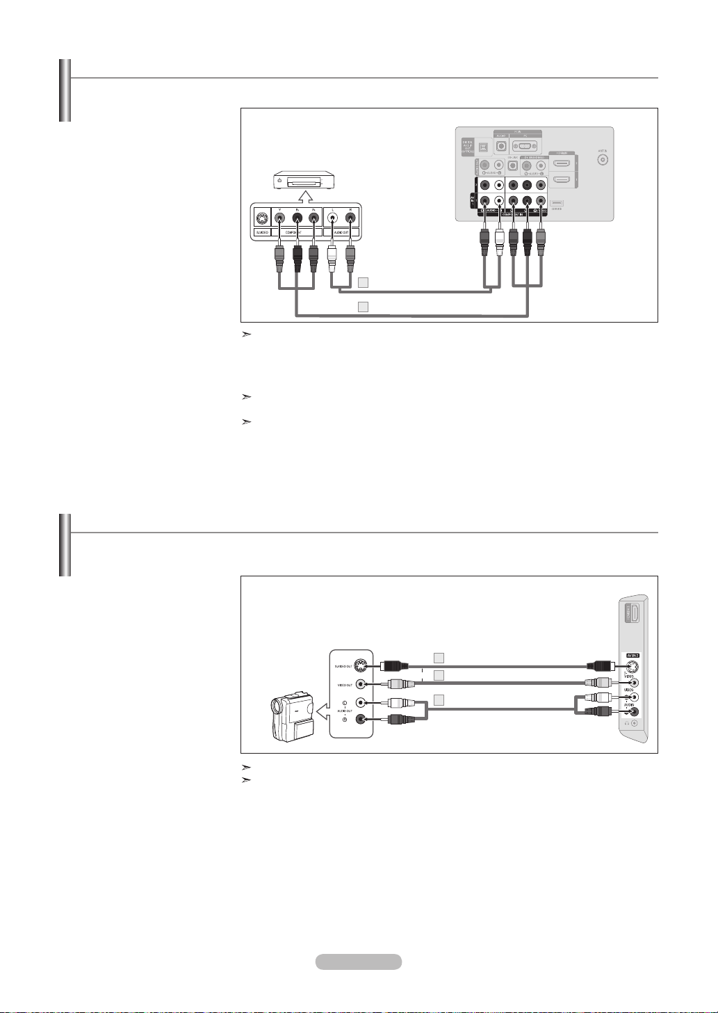
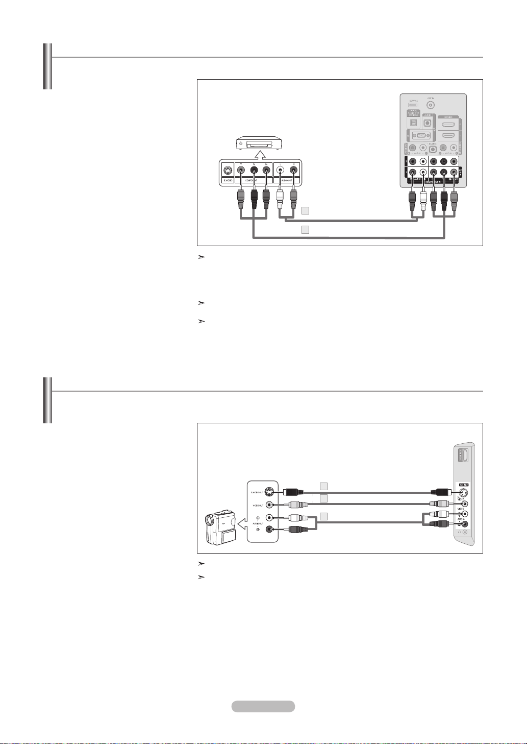
Connecting a DVD Player or Cable Box/Satellite receiver (Set-Top Box) via Component cables
The rear panel jacks on your TV make it easy to connect a DVD Player or Cable Box/Satellite receiver (Set-Top Box) to your TV.
1. Connect a Component Cable
between the COMPONENT
IN (1 or 2) [Y, PB, PR] jacks on
the TV and the COMPONENT
[Y, PB, PR] jacks on the DVD
Player or Cable Box/Satellite
receiver (Set-Top Box).
2. Connect Audio Cables between
the COMPONENT IN(1 or 2)
[R-AUDIO-L] jacks on the TV
and the AUDIO OUT jacks
on the DVD Player or Cable
Box/Satellite receiver (Set-Top
Box).
DVD Player or Cable Box /
Satellite receiver (Set-Top Box)
Audio Cable (Not supplied)
2
Component Cable (Not supplied)
1
Component video separates the video into Y (Luminance (brightness)), Pb (Blue) and
Pr (Red) for enhanced video quality.
Be sure to match the component video and audio connections.
For example, if connecting a Component video cable to COMPONENT IN 1, connect the
audio cable to COMPONENT IN 1 also.
Each DVD Player or Cable Box/Satellite receiver (Set-Top Box) has a different back panel
configuration.
When connecting a DVD Player or Cable Box/Satellite receiver (Set-Top Box), match the
color of the connection terminal to the cable.
TV Rear Panel
Connecting a Camcorder
The side panel jacks on your TV make it easy to connect a camcorder to your TV.
They allow you to view the camcorder tapes without using a VCR.
1. Connect a Video Cable
(or S-Video Cable) between
the AV IN 2 [VIDEO] (or
S-VIDEO) jack on the TV
and the VIDEO OUT jack on
the camcorder.
2. Connect Audio Cables
between the AV IN 2
[R-AUDIO-L] jacks on the TV
and the AUDIO OUT jacks
on the camcorder.
Camcorder
Each Camcorder has a different back panel configuration.
When connecting a Camcorder, match the color of the connection terminal to the cable.
or
S-Video Cable (Not supplied)
1
Video Cable (Not supplied)
1
Audio Cable (Not supplied)
2
TV Side Panel
English - 10
Page 13
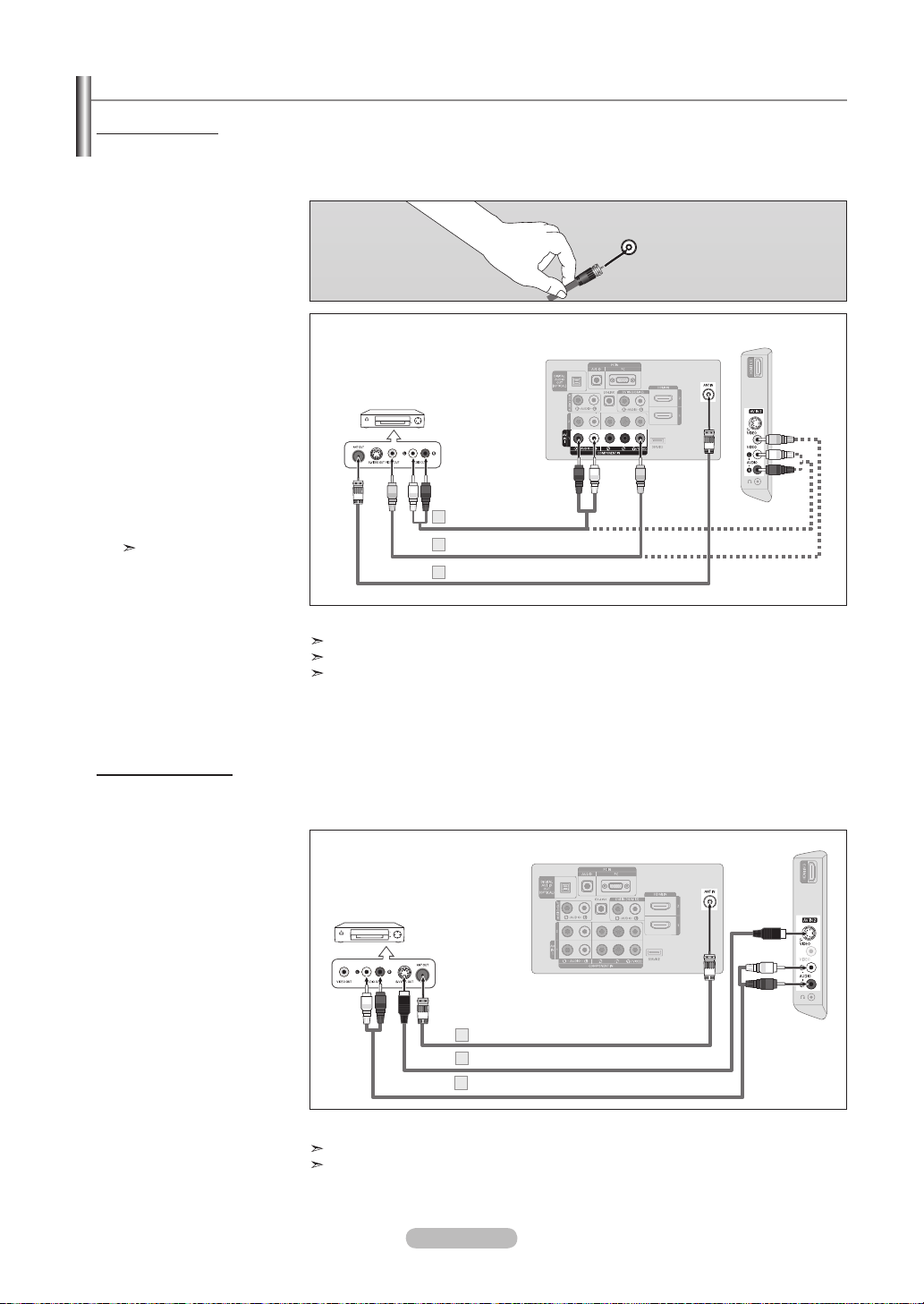
Connecting a VCR
Video Connection
These instructions assume that you have already connected your TV to an antenna or a cable TV system (according to the
instructions on pages 7~8). Skip step 1 if you have not yet connected to an antenna or a cable system.
1. Unplug the cable or antenna
from the back of the TV.
2. Connect the cable or antenna to
the ANT IN terminal on the back
of the VCR.
3. Connect an RF Cable between
the ANT OUT terminal on the
VCR and the ANT IN terminal
on the TV.
4. Connect a Video Cable
between the VIDEO OUT jack
on the VCR and the AV IN 1
[Y/VIDEO] or AV IN 2 [VIDEO]
jack on the TV.
5. Connect Audio Cables
between the AUDIO OUT
jacks on the VCR and the AV
IN 1 (or AV IN 2) [R-AUDIO-L]
jacks on the TV.
If you have a “mono”
(non-stereo) VCR, use a
Y-connector (not supplied)
to hook up to the right and
left audio input jacks of the
TV. If your VCRis stereo,
you mustm connect two
cables.
VCR Rear Panel
Audio Cable (Not supplied)
5
4
Video Cable (Not supplied)
RF Cable (Not supplied)3
Follow the instructions in “Viewing a VCR or Camcorder Tape” to view your VCR tape.
Each VCR has a different back panel configuration.
When connecting a VCR, match the color of the connection terminal to the cable.
When connecting to AV IN 1, the color of the AV IN 1 [Y/VIDEO] jack (Green) does not
match the color of the video cable (Yellow).
ANT IN
TV Rear Panel
TV Side Panel
S-Video Connection
Your Samsung TV can be connected to an S-Video jack on a VCR.
(This connection delivers a better picture when compared to the regular Video connection above.)
1. To begin, follow steps 1–3
in the previous section to
TV Rear Panel
connect the antenna or
cable to your VCR and your
TV.
VCR Rear Panel
2. Connect an S-Video Cable
between the S-VIDEO OUT
jack on the VCR and the
AV IN 2 [S-VIDEO] jack on
the TV.
3. Connect Audio Cables
between the AUDIO OUT
jacks on the VCR and the
AV IN 2 [R-AUDIO-L] jacks
on the TV.
RF Cable (Not supplied)
1
S-Video Cable (Not supplied)
2
Audio Cable (Not supplied)
3
An S-Video cable may be included with a VCR. (If not, check your local electronics store.)
Each VCR has a different back panel configuration.
When connecting a VCR, match the color of the connection terminal to the cable.
English - 11
TV Side Panel
Page 14
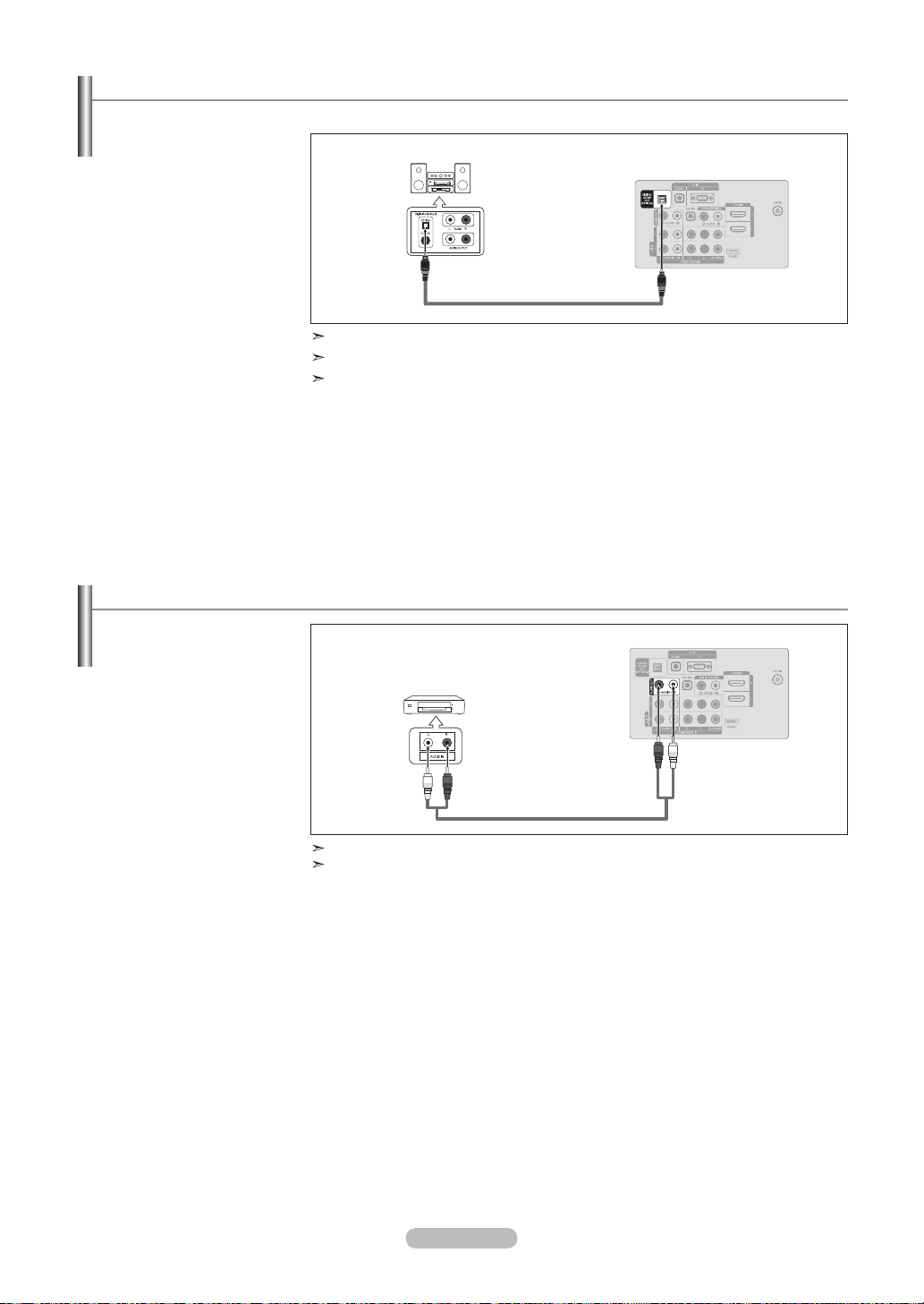
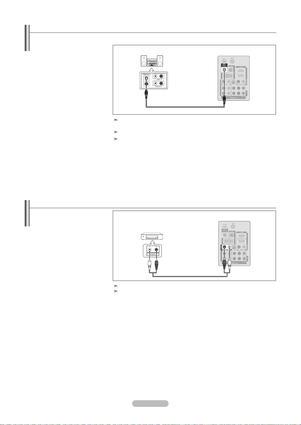
Connecting a Digital Audio System
The rear panel jacks on your TV make it easy to connect a Digital Audio System (Home theater/Receiver) to your TV.
1. Connect an Optical Cable
between the “DIGITAL AUDIO
OUT (OPTICAL)” jacks on the
Digital Audio System
TV Rear Panel
TV and the Digital Audio Input
jacks on the Digital Audio
System.
When a Digital Audio System
is connected to the “DIGITAL
AUDIO OUT (OPTICAL)” jack:
Decrease the volume of the
Optical Cable (Not supplied)
TV and adjust the volume
level with the system’s volume
control.
5.1CH audio is possible when the TV is connected to an external device supporting 5.1CH.
Each Digital Audio System has a different back panel configuration.
When the receiver (home theater) is set to On, you can hear sound output from the TV’s
Optical jack. When the TV is displaying a DTV(air) signal, the TV will send out 5.1 channel sound to the Home theater receiver. When the source is a digital component such as
a DVD and is connected to the TV via HDMI, only 2 channel sound will be heard from the
Home Theater receiver. If you want to hear 5.1 channel audio, connect the DIGITAL AUDIO
OUT (OPTICAL) jack on the DVD player or Cable/Satellite Box directly to an Amplifier or
Home Theater, not the TV.
Connecting an Amplier/DVD Home Theater
1. Connect Audio Cables
between the AUDIO OUT
[R-AUDIO-L] jacks on the TV
and AUDIO IN [R-AUDIO-L]
jacks on the Amplifier/DVD
Home Theater.
When an audio amplifier is
connected to the "AUDIO OUT
[R-AUDIO-L]" jacks: Decrease
the volume of the TV and
adjust the volume level with
the Amplifier’s volume control.
TV Rear Panel
Amplier/DVD Home Theater
Audio Cable (Not supplied)
Each Amplifier/DVD Home Theater has a different back panel configuration.
When connecting an Amplifier/DVD Home Theater, match the color of the connection
terminal to the cable.
English - 12
Page 15
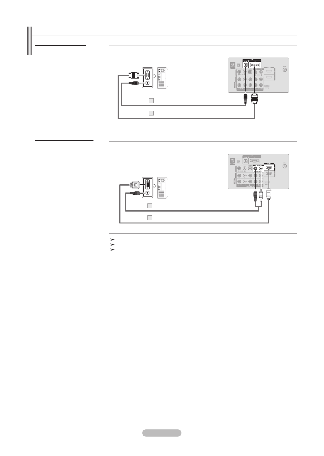
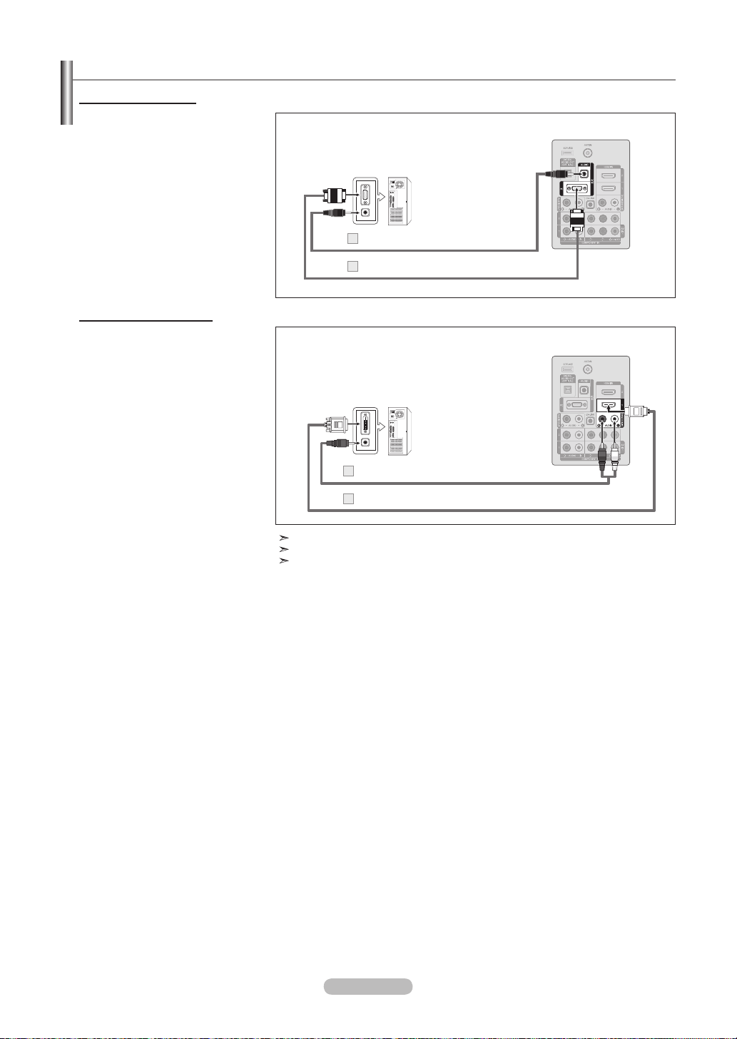
Connecting a PC
Using the D-Sub Cable
1. Connect a D-Sub Cable
between PC IN [PC] connector
on the TV and the PC output
connector on your computer.
2. Connect a PC Audio Cable
between the PC IN [AUDIO]
jack on the TV and the Audio
Out jack of the sound card on
your computer.
Using the HDMI/DVI Cable
1. Connect a HDMI/DVI cable
between the HDMI IN 2 jack
on the TV and the PC output
jack on your computer.
2. Connect a 3.5 mm Stereo
mini-plug/2RCA Cable
between the DVI IN(HDMI2)
[R-AUDIO-L] jack on the TV
and the Audio Out jack of the
sound card on your computer.
PC
PC Audio Cable (Not supplied)2
D-Sub Cable (Not supplied)
1
PC
3.5 mm Stereo mini-plug/2RCA Cable (Not supplied)
2
TV Rear Panel
TV Rear Panel
HDMI/DVI Cable (Not supplied)1
Each PC has a different back panel configuration.
When connecting a PC, match the color of the connection terminal to the cable.
When using an HDMI/DVI cable connection, you must use the HDMI IN 2 jack.
English - 13
Page 16
Connections (LN32A450C1D, LN37A450C1D)
Connecting VHF and UHF Antennas
If your antenna has a set of leads that look like the diagram to the right, see "Antennas with
300 Ω Flat Twin Leads" below.
If your antenna has one lead that looks like the diagram to the right, see "Antennas with 75
Ω Round Leads".
If you have two antennas, see "Separate VHF and UHF Antennas".
Antennas with 300 Ω Flat Twin Leads
If you are using an off-air antenna (such as a roof antenna or "rabbit ears") that has 300 Ω twin at leads, follow the directions
below.
1. Place the wires from the twin leads under the screws on a 300-75 Ω adapter
(not supplied).
Use a screwdriver to tighten the screws.
2. Plug the adaptor into the ANT IN terminal on the back of the TV.
ANT IN
Antennas with 75 Ω Round Leads
1. Plug the antenna lead into the ANT IN terminal on the back of the TV.
ANT IN
Separate VHF and UHF Antennas
If you have two separate antennas for your TV (one VHF and one UHF), you must combine the two antenna signals before
connecting the antennas to the TV. This procedure requires an optional combiner-adaptor (available at most electronics shops).
1. Connect both antenna leads to the combiner.
UHF
VHF
2. Plug the combiner into the ANT IN terminal on the bottom of the rear panel.
ANT IN
UHF
VHF
English - 14
Page 17

Connecting Cable TV
To connect to a cable TV system, follow the instructions below.
Cable without a Cable Box
1. Plug the incoming cable into the ANT IN terminal on the back of the TV.
Because this TV is cable-ready, you do not need a cable box to view unscrambled cable channels.
ANT IN
Connecting to a Cable Box that Descrambles All Channels
1. Find the cable that is connected to the ANT OUT terminal on your cable box.
This terminal might be labeled "ANT OUT", "VHF OUT" or simply, "OUT".
ANT IN
ANT OUT
2. Connect the other end of this cable to the ANT IN terminal on the back of the TV.
ANT IN
Connecting to a Cable Box that Descrambles Some Channels
If your cable box descrambles only some channels (such as premium channels), follow the instructions below. You will need a twoway splitter, an RF (A/B) switch and four lengths of RF cable. (These items are available at most electronics stores.)
Find and disconnect the cable that is
1.
connected to the ANT IN terminal on your
cable box.
This terminal might be labeled "ANT IN",
"VHF IN" or simply, "IN".
ANT IN
2. Connect this cable to a two-way splitter.
Incoming
3. Connect an RF cable between the
OUTPUT
terminal on the splitter and the IN terminal
on the cable box.
Incoming
cable
cable
Splitter
Splitter
Cable Box
4. Connect an RF cable between the
ANT OUT terminal on the cable box and
the B–IN terminal on the RF(A/B) switch.
Incoming
cable
Splitter
Cable Box
RF (A/B)
Switch
5. Connect another cable between the other
OUT terminal on the splitter and the A–IN
terminal on the RF (A/B) switch.
Incoming
cable
Splitter
Cable Box
RF (A/B)
Switch
6. Connect the last RF cable between the
OUT terminal on the RF (A/B) switch and
ANT IN
the ANT IN terminal on the rear of the TV.
Incoming
cable
Splitter
Cable Box
RF (A/B)
Switch
TV Rear
After you have made this connection, set the A/B switch to the "A" position for normal viewing. Set the A/B switch to the "B" position to
view scrambled channels. (When you set the A/B switch to "B", you will need to tune your TV to the cable box’s output channel, which is
usually channel 3 or 4.)
English - 15
Page 18
Connecting a DVD Player or Cable Box/Satellite receiver (Set-Top Box) via HDMI
This connection can only be made if there is an HDMI Output connector on the external device.
1. Connect an HDMI Cable between
the HDMI IN (1, 2 or 3) jack on the
TV and the HDMI jack on the
DVD Player or Cable Box/Satellite
receiver (Set-Top Box).
DVD Player or Cable Box/Satellite
receiver (Set-Top Box) Rear Panel
TV Rear Panel
TV Side Panel
or
What is HDMI?
HDMI Cable (Not supplied)
• HDMI(High-Definition Multimedia Interface), is an interface that enables the
transmission of digital audio and video signals using a single cable.
• The difference between HDMI and DVI is that the HDMI device is smaller
in size and has the HDCP (High Bandwidth Digital Copy Protection) coding
feature installed.
Each DVD Player or Cable Box/Satellite receiver (Set-Top Box) has a different
back panel configuration.
Connecting a DVD Player or Cable Box/Satellite receiver (Set-Top Box) via DVI
This connection can only be made if there is a DVI Output connector on the external device.
1. Connect a DVI to HDMI Cable or
DVI-HDMI Adapter between the
HDMI IN 1 jack on the TV and the
DVI jack on the DVD Player or Cable
Box/Satellite receiver (Set-Top Box).
2. Connect Audio Cables between the
DVI IN (HDMI 1) [R-AUDIO-L] jack
on the TV and the DVD Player or
Cable Box/Satellite receiver (Set-Top
Box).
DVD Player or Cable Box/
Satellite receiver (Set-Top Box)
Audio Cable
2
(Not supplied)
TV Rear Panel
DVI to HDMI Cable (Not supplied)1
Each DVD Player or Cable Box/Satellite receiver (Set-Top Box) has a different
back panel configuration.
When connecting a DVD Player or Cable Box/Satellite receiver (Set-Top Box),
match the color of the connection terminal to the cable.
When using an HDMI/DVI cable connection, you must use the HDMI IN 1 jack.
English - 16
Page 19
Connecting a DVD Player or Cable Box/Satellite receiver (Set-Top Box) via Component cables
The rear panel jacks on your TV make it easy to connect a DVD Player or Cable Box/Satellite receiver (Set-Top Box) to your TV.
1. Connect a Component Cable
between the COMPONENT IN
(1 or 2) [Y, PB, PR] jacks on the TV
and the COMPONENT [Y, PB, PR]
jacks on the DVD Player or Cable
Box/Satellite receiver (Set-Top Box).
2. Connect Audio Cables between the
COMPONENT IN(1 or 2)
[R-AUDIO-L] jacks on the TV
and the AUDIO OUT jacks on the
DVD Player or Cable Box/Satellite
receiver (Set-Top Box).
DVD Player or Cable Box /
Satellite receiver (Set-Top Box)
Audio Cable (Not supplied)
2
Component Cable (Not supplied)
1
Component video separates the video into Y (Luminance (brightness)), Pb (Blue)
and Pr (Red) for enhanced video quality. Be sure to match the component video and
audio connections.
For example, if connecting a Component video cable to COMPONENT IN 1,
connect the audio cable to COMPONENT IN 1 also.
Each DVD Player or Cable Box/Satellite receiver (Set-Top Box) has a different back
panel configuration.
When connecting a DVD Player or Cable Box/Satellite receiver (Set-Top Box), match the
color of the connection terminal to the cable.
TV Rear Panel
Connecting a Camcorder
The side panel jacks on your TV make it easy to connect a camcorder to your TV.
They allow you to view the camcorder tapes without using a VCR.
1. Connect a Video Cable
(or S-Video Cable) between the
AV IN 2 [VIDEO] (or S-VIDEO)
jack on the TV and the VIDEO
OUT jack on the camcorder.
2. Connect Audio Cables between
the AV IN 2 [R-AUDIO-L] jacks
on the TV and the AUDIO OUT
jacks on the camcorder.
Camcorder
Each Camcorder has a different back panel configuration.
When connecting a Camcorder, match the color of the connection terminal to the
cable.
or
S-Video Cable (Not supplied)
1
Video Cable (Not supplied)
1
Audio Cable (Not supplied)
2
TV Side Panel
English - 17
Page 20

Connecting a VCR
Video Connection
These instructions assume that you have already connected your TV to an antenna or a cable TV system (according to the
instructions on pages 14~15). Skip step 1 if you have not yet connected to an antenna or a cable system.
1. Unplug the cable or antenna from
the back of the TV.
2. Connect the cable or antenna to the
ANT IN terminal on the back of the
VCR.
3. Connect an RF Cable between the
ANT OUT terminal on the VCR and
the ANT IN terminal on the TV.
4. Connect a Video Cable between the
VIDEO OUT jack on the VCR and
the AV IN 1 [Y/VIDEO] or AV IN 2
[VIDEO] jack on the TV.
5. Connect Audio Cables between the
AUDIO OUT jacks on the VCR and
the AV IN 1 (or AV IN 2)
[R-AUDIO-L] jacks on the TV.
If you have a “mono”(non-stereo)
VCR, use aY-connector (not
supplied) to hook up to the right
and left audio input jacks of the
TV. If your VCR is stereo, you
must connect two cables.
VCR Rear Panel
Audio Cable (Not supplied)
5
Video Cable (Not supplied)
4
RF Cable (Not supplied)3
ANT IN
TV Rear Panel
TV Side Panel
Follow the instructions in “Viewing a VCR or Camcorder Tape” to view your VCR tape.
Each VCR has a different back panel configuration.
When connecting a VCR, match the color of the connection terminal to the cable.
When connecting to AV IN 1, the color of the AV IN 1 [Y/VIDEO] jack (Green) does
not match the color of the video cable (Yellow).
S-Video Connection
Your Samsung TV can be connected to an S-Video jack on a VCR.
(This connection delivers a better picture when compared to the regular Video connection above.)
1. To begin, follow steps 1–3 in the
TV Rear Panel
previous section to connect the
antenna or cable to your VCR and
your TV.
2. Connect an S-Video Cable
VCR Rear Panel
between the S-VIDEO OUT jack
on the VCR and the AV IN 2
[S-VIDEO] jack on the TV.
3. Connect Audio Cables between
the AUDIO OUT jacks on the VCR
and the AV IN 2 [R-AUDIO-L]
jacks on the TV.
RF Cable (Not supplied)
1
2
S-Video Cable (Not supplied)
Audio Cable (Not supplied)
3
An S-Video cable may be included with a VCR. (If not, check your local electronics store.)
Each VCR has a different back panel configuration.
When connecting a VCR, match the color of the connection terminal to the cable.
TV Side Panel
English - 18
Page 21
Connecting a Digital Audio System
The rear panel jacks on your TV make it easy to connect a Digital Audio System (Home theater/Receiver) to your TV.
1. Connect an Optical Cable between
the “DIGITAL AUDIO OUT
(OPTICAL)” jacks on the TV and
the Digital Audio Input jacks on the
Digital Audio System.
When a Digital Audio System is
connected to the “DIGITAL AUDIO
OUT (OPTICAL)” jack: Decrease
the volume of the TV and adjust
the volume level with the system’s
volume control.
Digital Audio System TV Rear Panel
Optical Cable (Not supplied)
5.1CH audio is possible when the TV is connected to an external device supporting
5.1CH.
Each Digital Audio System has a different back panel configuration.
When the receiver (home theater) is set to On, you can hear sound output from
the TV’s Optical jack. When the TV is displaying a DTV(air) signal, the TV will send
out 5.1 channel sound to the Home theater receiver. When the source is a digital
component such as a DVD and is connected to the TV via HDMI, only 2 channel
sound will be heard from the Home Theater receiver. If you want to hear 5.1 channel
audio, connect the DIGITAL AUDIO OUT (OPTICAL) jack on the DVD player or
Cable/Satellite Box directly to an Amplifier or Home Theater, not the TV.
Connecting an Amplier/DVD Home Theater
1. Connect Audio Cables between the
AUDIO OUT [R-AUDIO-L] jacks on
the TV and AUDIO IN [R-AUDIO-L]
jacks on the Amplifier/DVD Home
Theater.
When an audio amplifier is
connected to the "AUDIO OUT
[R-AUDIO-L]" jacks: Decrease the
volume of the TV and adjust the
volume level with the Amplifier’s
volume control.
Amplier/DVD Home Theater
Audio Cable (Not supplied)
Each Amplifier/DVD Home Theater has a different back panel configuration.
When connecting an Amplifier/DVD Home Theater, match the color of the
connection terminal to the cable.
TV Rear Panel
English - 19
Page 22
Connecting a PC
Using the D-Sub Cable
1. Connect a D-Sub Cable between
PC IN [PC] connector on the TV
and the PC output connector on
your computer.
2. Connect a PC Audio Cable
between the PC IN [AUDIO] jack
on the TV and the Audio Out jack of
the sound card on your computer.
Using the HDMI/DVI Cable
1. Connect a HDMI/DVI cable
between the HDMI IN 1 jack on the
TV and the PC output jack on your
computer.
2. Connect a 3.5 mm Stereo
mini-plug/2RCA Cable between
the DVI IN(HDMI1) [R-AUDIO-L]
jack on the TV and the Audio Out
jack of the sound card on your
computer.
PC
PC Audio Cable (Not supplied)2
D-Sub Cable (Not supplied)
1
PC
3.5 mm Stereo mini-plug/2RCA Cable (Not supplied)
2
TV Rear Panel
TV Rear Panel
HDMI/DVI Cable (Not supplied)1
Each PC has a different back panel configuration.
When connecting a PC, match the color of the connection terminal to the cable.
When using an HDMI/DVI cable connection, you must use the HDMI IN 1 jack.
English - 20
Page 23
Operation
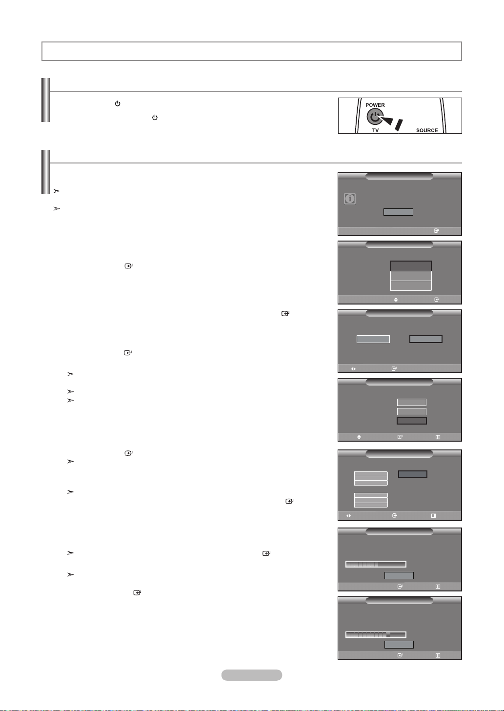
Turning the TV On and Off
Press the POWER button on the remote control.
You can also use the POWER button on the TV.
Plug & Play Feature
When the TV is initially powered on, basic settings proceed automatically and
subsequently.
The Screen Saver is activated if there is no remote control key input for longer than 1
minute while “Plug & Play” is running.
The Screen Saver is activated if there is no operating signal for longer than 15
minutes.
1. Press the POWER button on the remote control.
The message “Menu Language, Store Demo, Channels and Time will be set.” is
displayed.
Press the ENTER button, then “Select the language of the OSD” menu
is automatically displayed.
2. Press the ▲ or ▼ button to select language, then press the ENTER button.
The message “Select ‘Home Use’ when installing this TV in your home.” is
displayed.
3. Press the ◄ or ► button to select “Store Demo” or “Home Use”, then
press the ENTER button.
The message “Select the antennas to memorize.” is displayed.
We recommend setting the TV to “Home Use” mode for the best picture in your
home environment.
“Store Demo” mode is only intended for use in retail environments.
If the unit is accidentally set to “Store Demo” mode and you want to return to
“Home Use” (Standard): Press the Volume button on the TV. When the volume
OSD is displayed, press and hold the MENU button on the TV for 5 seconds.
4. Press the ▲ or ▼ button to memorize the channels of the selected connection.
Press the ENTER button to select “Start”.
Air: “Air” antenna signal.
Cable: “Cable” antenna signal.
Auto: “Air” and “Cable” antenna signals.
In Cable mode, you can select the correct signal source among STD, HRC, and
IRC by pressing the ▲, ▼, ◄ or ► button, then press the ENTER button. If
you have Digital cable, select the cable system signal source for both Analog and
Digital. Contact your local cable company to identify the type of cable system that
exists in your particular area.
5. The TV will begin memorizing all of the available channels.
To stop the search before it has finished, press the ENTER button with “Stop”
selected.
After all the available channels are stored, it starts to remove scrambled channels
(see page 39). The Auto program menu then reappears.
Press the ENTER button when channel memorization is complete.
The message “Set the Clock Mode.” is displayed.
Plug & Play
Menu Language, Store Demo,
Channels and Time will be set.
Start
Enter
Plug & Play
Select the language of the OSD.
Language :
Select ‘Home Use’ when installing this TV in your
home.
Store Demo
Move Enter
Select the antennas to memorize.
Air
Cable
Auto
Move Enter Skip
Selects a cable signal type for your location.
Analog
STD
HRC
IRC
Digital
STD
HRC
IRC
Move Enter Skip
Auto Program in Progress.
DTV Air : 02 Air : 11
DTV Cable : 23 Cable : 21
Enter Skip
Removing scrambled channel.
English
Español
Français
Move Enter
Plug & Play
Home Use
Plug & Play
Start
Start
Start
Plug & Play
Start
Plug & Play
Auto Program
Cable 50
Stop
Plug & Play
Auto Program
50 %
English - 21
DTV Cable 41
Stop
Enter Skip
77 %
Page 24
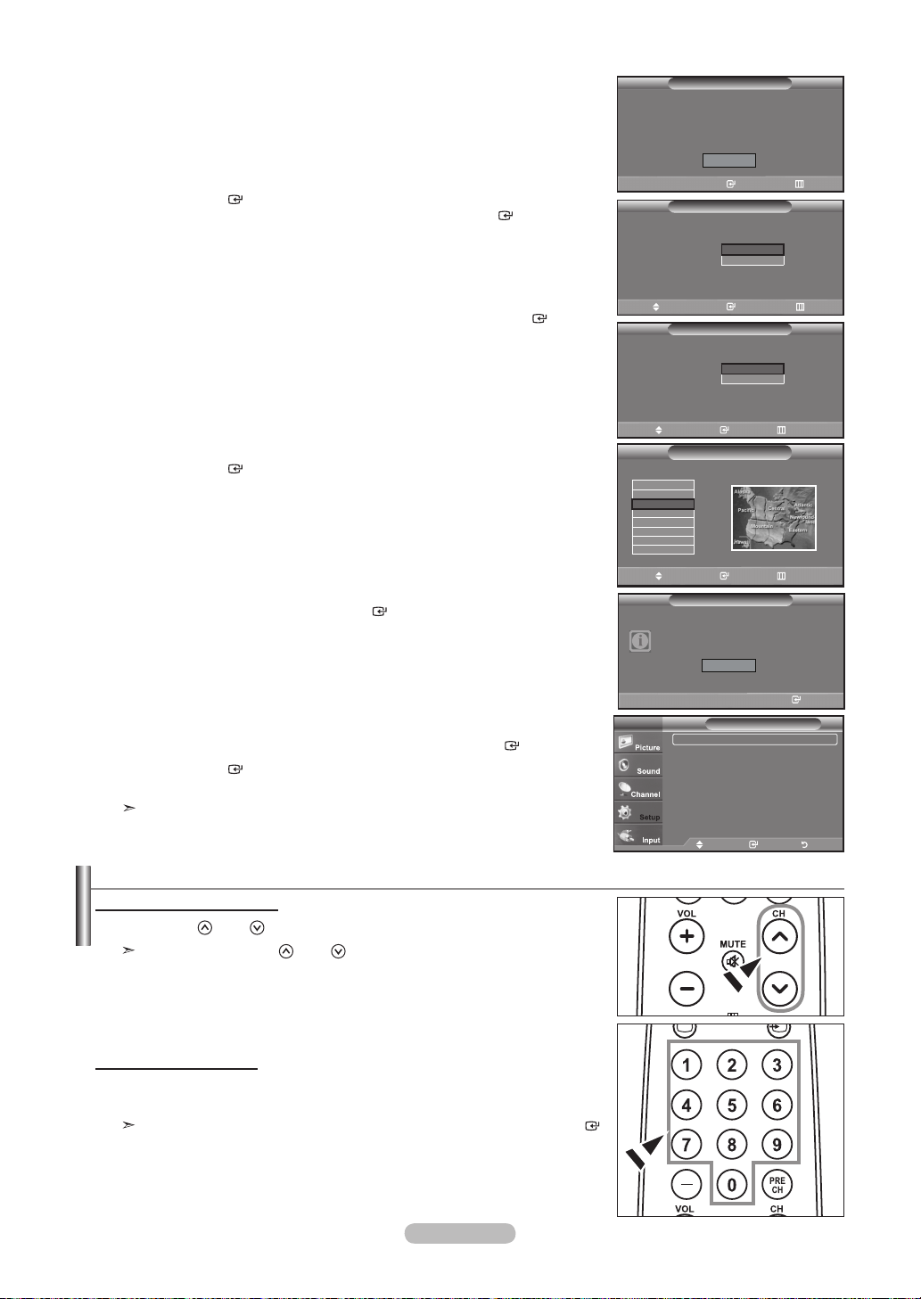
6. Press the ENTER button.
Press the ▲ or ▼ button to select “Auto”, then Press the ENTER button.
The message “Set to daylight saving time.” is displayed.
If you select “Manual”, “Enter the current date and time.” is displayed.
(See page 48)
Auto Program
Plug & Play
Auto Program is completed.
75 Channels are memorized.
DTV Air : 24 Air : 1
DTV Cable : 17 Cable : 33
OK
Enter Skip
Plug & Play
Set the Clock Mode.
Clock Mode :
Auto
Manual
7. Press the ▲ or ▼ button to select “Off” or “On”, then press the ENTER button.
The message “Select the time zone in which you live.” is displayed.
8. Press the ▲ or ▼ button to highlight the time zone for your local area.
Press the ENTER button. If you have received a digital signal, the time will be
set automatically.
If not, see page 48 to set the clock.
9. The message “Enjoy your watching.” is displayed.
When you have finished, press the ENTER button.
If you want to reset this feature...
1. Press the MENU button to display the menu.
Press the ▲ or ▼ button to select "Setup", then press the ENTER button.
2. Press the ENTER button again to select “Plug & Play”.
For further details on setting up options, refer to the pages 21~22.
The “Plug & Play” feature is only available in the TV mode.
Move Enter Skip
Set to daylight saving time.
DST :
Move Enter Skip
Select the time zone in which you live.
Newfoundland
Atlantic
Eastern
Central
Mountain
Pacific
Alaska
Hawaii
Move Enter Skip
TV
Plug & Play
Off
On
Plug & Play
Plug & Play
Enjoy your watching.
OK
Enter
Plug & Play ►
Language : English ►
Time ►
V-Chip ►
Caption ►
External Settings ►
Entertainment : Off ►
▼ More
Move Enter Return
Setup
Changing Channels
Using the Channel Buttons
1. Press the CH
When you press the CH
sequence.
You will see all the channels that the TV has memorized. (The TV must have
memorized at least three channels). You will not see channels that were either
erased or not memorized. See page 24 to memorize channels.
Using the Number Buttons
1. Press the number buttons to go directly to a channel. For example, to select
channel 27, press 2, then 7.
For quick channel change, press the number buttons, then press the ENTER
button.
or CH button to change channels.
button, the TV changes channels in
or CH
English - 22
Page 25
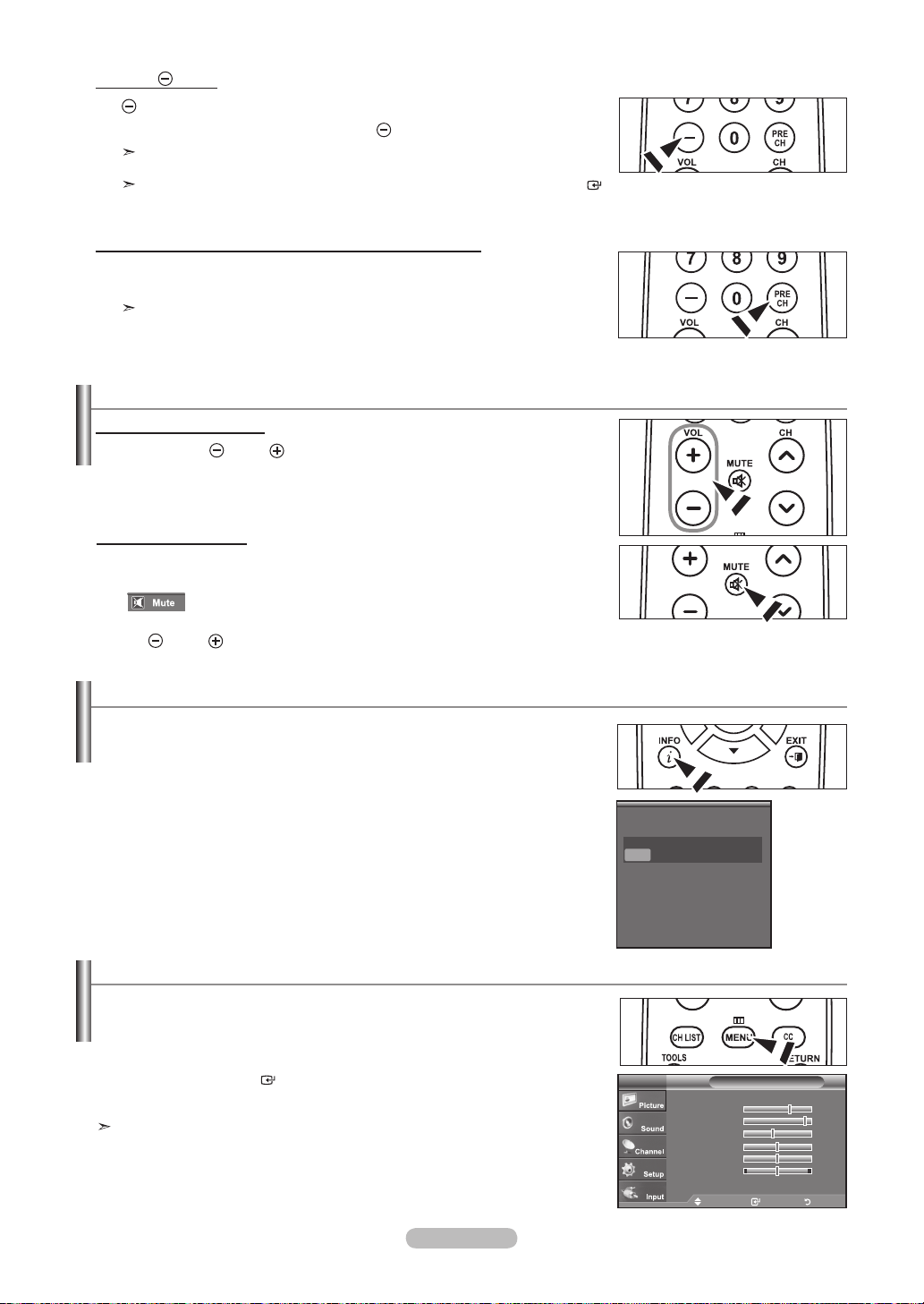
Using the Button
The button is used to select stations that broadcast a digital signal.
1. For example, for Channel 7-1, press 7, then , then 1.
HD indicates the TV is receiving a Digital High Definition signal. SD indicates
the TV is receiving a Standard Definition signal.
For quick channel change, press the number buttons, then press the ENTER
button.
Using the PRE CH Button to select the Previous Channel
1. Press the PRE CH button.
The TV will switch to the last channel viewed.
To quickly switch between two channels that are far apart, tune to one
channel, then use the number button to select the second channel. Then
use the PRE CH button to quickly alternate between them.
Adjusting the Volume
Using the Volume Buttons
1. Press the
Using the MUTE button
At any time, you can cut off the sound using the MUTE button.
1. Press MUTE button and the sound cuts off.
" " is displayed on the screen.
2. To turn mute off, press the MUTE button again or simply press the
VOL or VOL button.
VOL or VOL button to increase or decrease the volume.
Viewing the Display
The display identies the current channel and the status of certain audio-video settings.
1. Press the INFO button on the remote control.
The TV will display the channel, the type of sound,
and the status of certain picture and sound settings.
Press the INFO button once more or wait approximately 10 seconds and the
➣
display disappears automatically.
Viewing the Menus
1. With the power on, press the MENU button.
The main menu appears on the screen. The menu’s left side has icons:
Picture, Sound, Channel, Setup, Input.
2. Press the ▲ or ▼ button to select one of the icons.
Then press the ENTER
3. Press the
EXIT button to exit.
The on-screen menus disappear from the screen after about one minute.
button to access the icon’s sub-menu.
Air 7
Mono
Picture Mode : Standard
Sound Mode : Custom
MTS : Stereo
V-Chip : Off
Caption : Off
5 : 54 pm
Mode : Standard ►
Backlight 7
Contrast 95
Brightness 45
Sharpness 50
Color 50
Tint G 50 R 50
▼ More
Move Enter Exit
PictureTV
English - 23
Page 26
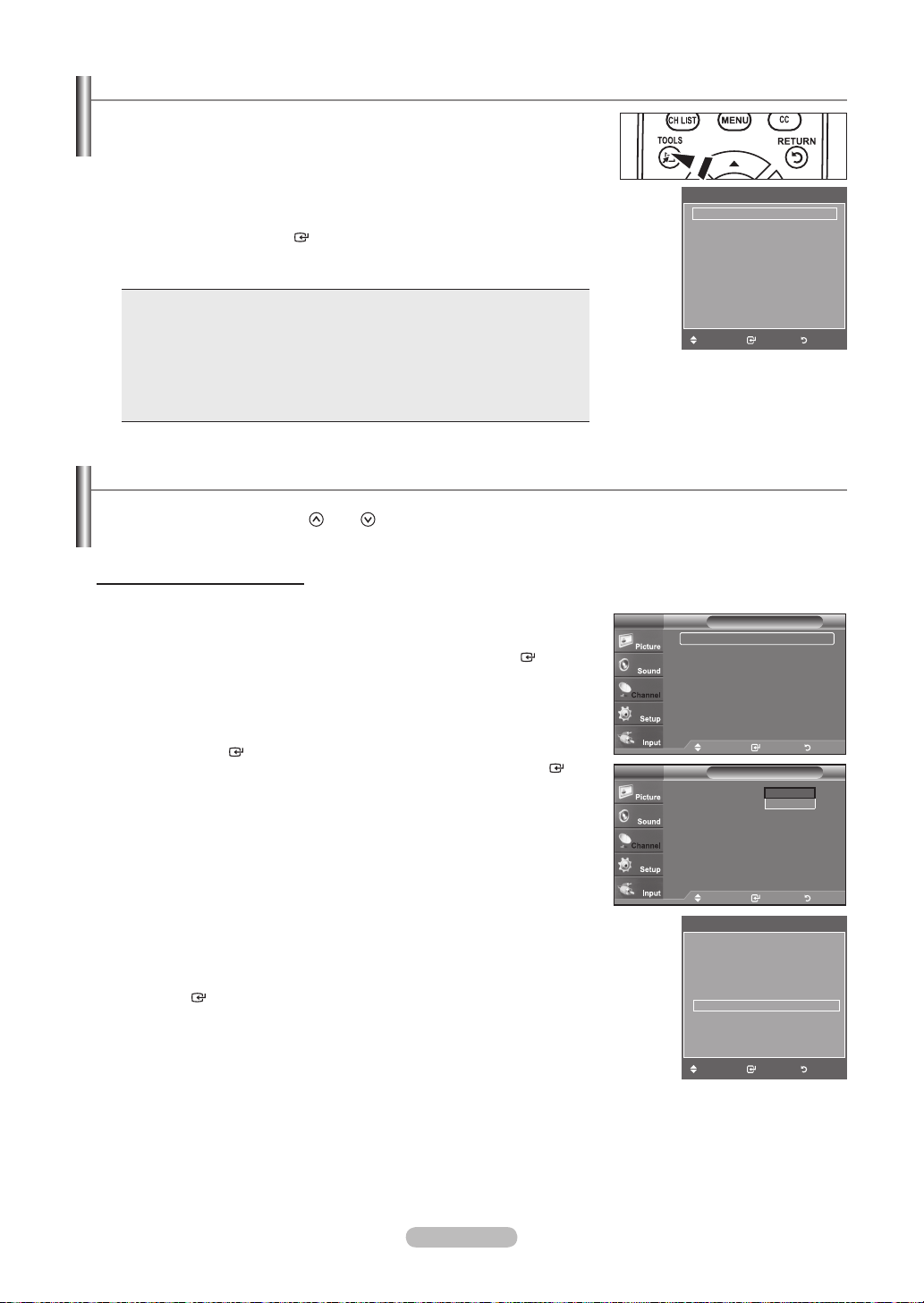
Using the TOOLS Button
You can use the TOOLS button to select your frequently used functions quickly and
easily. The “Tools” menu changes depending on which external input mode you are
viewing.
1. Press the TOOLS button.
The “Tools” menu will appear.
2. Press the ▲ or ▼ button to select a menu.
3. Press the ▲/▼/◄/►/ENTER buttons to display, change, or use the selected
items.For a more detailed description of each function, refer to the corresponding
page.
Anynet+(HDMI-CEC)
Picture Mode : Standard
Sound Mode : Custom
Sleep Timer : Off
Add to Favorite
Switch to Air
Tools
• Anynet+(HDMI-CEC), see page 64
• Picture Mode, see page 27
• Sound Mode, see page 35
Move Enter Exit
• Sleep Timer, see page 50
• Add to Favorite, see page 41
• Switch to Air, see page 24
• Auto Adjustment, see page 46
Memorizing the Channels
Your TV can memorize and store all of the available channels for both "off-air" (Air) and "Cable" channels. After the available
channels are memorized, use the CH
by entering the channel digits. There are three steps for memorizing channels: selecting a broadcast source, memorizing the
channels (automatic) and adding or deleting channels (Channel Lists).
Selecting the Video Signal-source
Before your television can begin memorizing the available channels, you must specify the
type of signal source that is connected to the TV (i.e. an Air or a Cable system).
1. Press the MENU button to display the menu.
Press the ▲ or ▼ button to select "Channel", then press the ENTER
or CH button to scan through the channels. This eliminates the need to change channels
Channel
►
button.
TV
Antenna : Air ►
Auto Program ►
Clear Scrambled Channel ►
Channel List ►
Name ►
Fine Tune
Signal Strength ►
2. Press the ENTER
Press the ▲ or ▼ button to select “Air” or “Cable”, then press the ENTER button.
button to select “Antenna”.
Press the EXIT button to exit.
Easy Setting
1.
Press the TOOLS button on the remote control.
2. Press the ▲ or ▼ button to select “Switch to Air” (or “Switch to Cable”), then press, then press
the ENTER button.
English - 24
TV
Antenna : Air
Auto Program
Clear Scrambled Channel
Channel List
Name
Fine Tune
Signal Strength
Move Enter Return
Channel
Air
Cable
Move Enter Return
Tools
Anynet+(HDMI-CEC)
Picture Mode : Standard
Sound Mode : Custom
Sleep Timer Off
Add to Favorite
Switch to Air
Move Enter Exit
Page 27
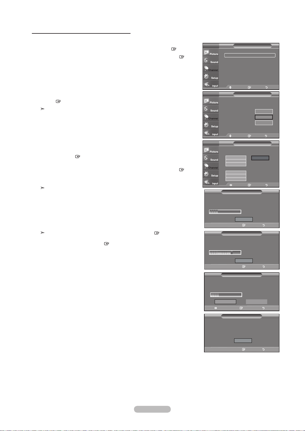
Storing Channels in Memory (Automatic Method)
1. Press the MENU button to display the menu.
Press the ▲ or ▼ button to select “Channel”, then press the ENTER button.
2. Press the ▲ or ▼ button to select "Auto Program", then press the ENTER
button.
3. Press the ▲ or ▼ button to select the antenna connection, then press the
ENTER button.
Air: “Air” antenna signal.
Cable: “Cable” antenna signal.
Auto: “Air” and “Cable” antenna signals.
When selecting the Cable TV system:
4.
Press the ENTER button to start the auto program.
Press the ◄ or ► button, then press the ▲ or ▼ to select the correct analog signal
cable system source among “STD”, “HRC”, and “IRC”. Press the ENTER button.
If you have Digital cable TV, select the cable system signal source for both Analog
and Digital.
STD, HRC and IRC identify various types of cable TV systems. Contact your
local cable company to identify the type of cable system that exists in your
particular area. At this point the signal source has been selected.
5. The TV begins memorizing all available stations.
After all the available channels are stored, it start to remove scrambled
channels(see page 39).
If you want to stop Auto Programming, press the ENTER button. The “Stop
Auto Program?” message will be displayed. Select “Yes” by pressing the ◄ or ►
button, then press the ENTER button.
Press the EXIT button to exit.
TV
Antenna : Air ►
Auto Program ►
Clear Scrambled Channel ►
Channel List ►
Name ►
Fine Tune
Signal Strength ►
TV
Selects the antenna to execute the Auto
Program function.
Air
Cable
Auto
TV
Selects a cable signal type for your location.
STD
HRC
IRC
STD
HRC
IRC
Auto Program in Progress.
DTV Cable : -- Cable : 11
Enter Return
Removing scrambled channel.
Enter Return
Stop Auto Program?
DTV Cable : -- Cable : 11
Yes
Move Enter Return
Auto Program is completed.
99 Channels are memorized.
DTV Cable : 65, Cable : 34
Enter Return
Channel
►
Move Enter Return
Auto Program
Start
Start
Start
Move Enter Return
Move Enter Return
Auto Program
Analog
Digital
Move Enter Return
Move Enter Return
Auto Program
Plug & Play
Auto Program
Auto Program
Plug & Play
Auto Program
Auto Program
Auto Program
Stop
Stop
OK
Start
Cable 24
DTV Cable 55
80 %
No
11 %
11 %
English - 25
Page 28
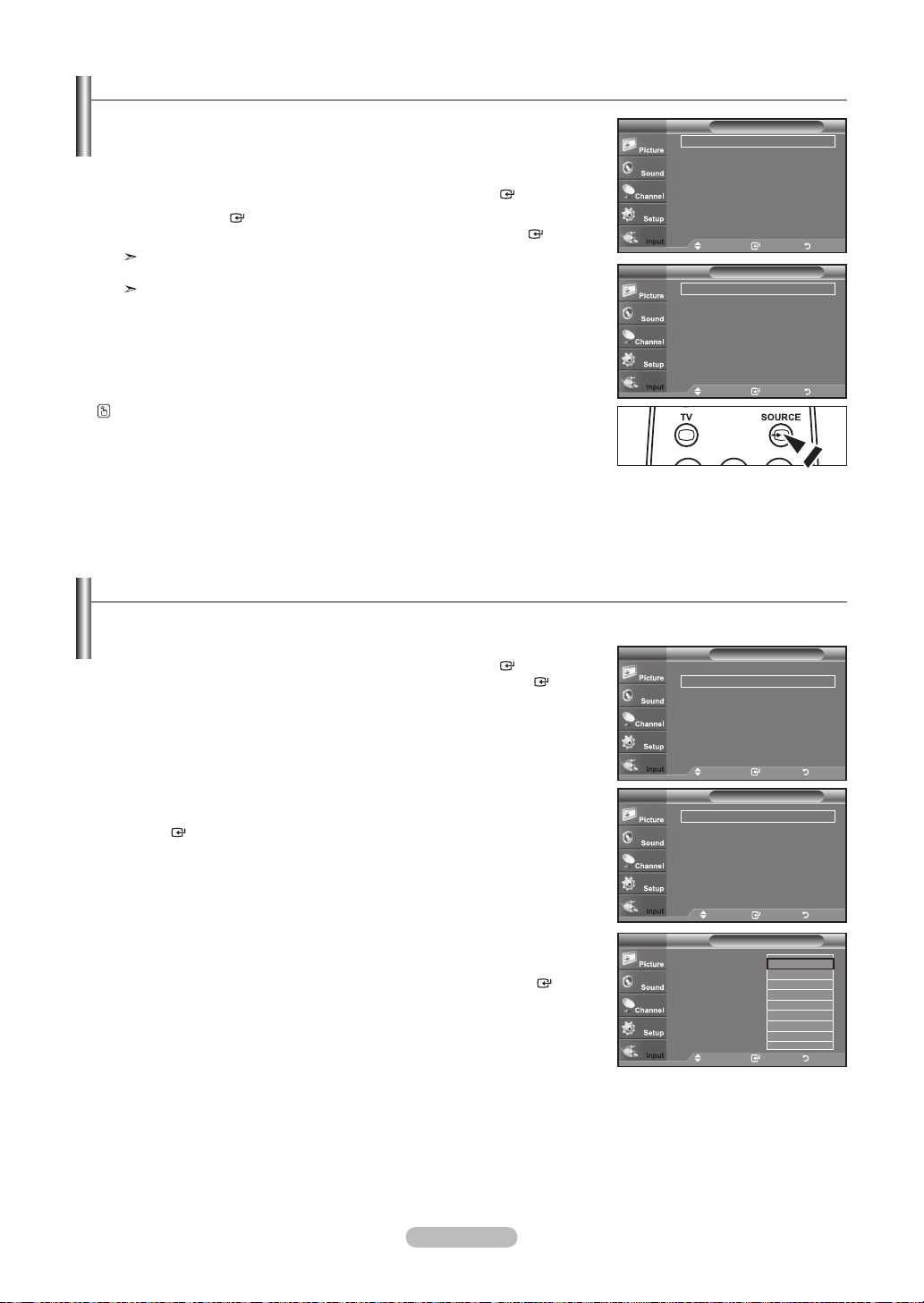
To Select the Source
Use to select TV or other external input sources such as DVD players or Cable Box/
Satellite receivers (Set-Top Box) connected to the TV. Use to select the input source
of your choice.
1. Press the MENU button to display the menu.
Press the▲ or ▼ button to select “Input”, then press the ENTER button.
Press the ENTER
2.
Press the ▲ or ▼ button to select signal source, then press the ENTER
button to select "Source List".
button.
Available signal sources: TV, AV1, AV2, S-Video, Component1, Component2,
PC, HDMI1, HDMI2, HDMI3.
You can choose only those external devices that are connected to the TV.
Press the SOURCE button on the remote control to view an external signal source.
To Edit the Input Source Name
Name the device connected to the input jacks to make your input source selection easier.
1. Press the MENU button to display the menu.
Press the▲ or ▼ button to select “Input”, then press the ENTER button.
Press the ▲ or ▼ button to select "Edit Name", then press the ENTER
button.
TV
Source List : TV ►
Edit Name ►
Anynet+ (HDMI-CEC)
Move Enter Return
TV
AV1 : ---AV2 : ---S-Video : ---Component1 : ---Component2 : ---PC : ----
▼ More
Move Enter Return
TV
Source List : TV ►
Edit Name ►
Anynet+ (HDMI-CEC)
Input
Source ListTV
Input
2.
Press the ▲ or ▼ button to select "AV1", "AV2", "S-Video", "Component1",
"Component2", "PC", "HDMI1", "HDMI2", "HDMI3" input jack, then press the
ENTER
3.
Press the ▲ or ▼ button to select “VCR”, “DVD”, “Cable STB”, “Satellite STB”,
button.
“PVR STB”, “AV Receiver”, “Game”, “Camcorder”, “PC”, “TV”, “IPTV”, “Blu-Ray”,
“HD DVD”, “Digital Media Adapter” input source, then press the ENTER button.
Press the EXIT button to exit.
English - 26
Move Enter Return
Edit NameTV
AV1 : ---- ►
AV2 : ---- ►
S-Video : ---- ►
Component1 : ---- ►
Component2 : ---- ►
PC : ---- ►
HDMI1 : ---- ►
▼ More
Move Enter Return
AV1 : ----
AV2 : ----
S-Video : ----
Component1 : ----
Component2 : ----
PC : ----
HDMI1 : ----
▼ More
Edit NameTV
----
VCR
DVD
Cable STB
Satellite STB
PVR STB
AV Receiver
Game
Move Enter Return
▼
Page 29
Picture Control
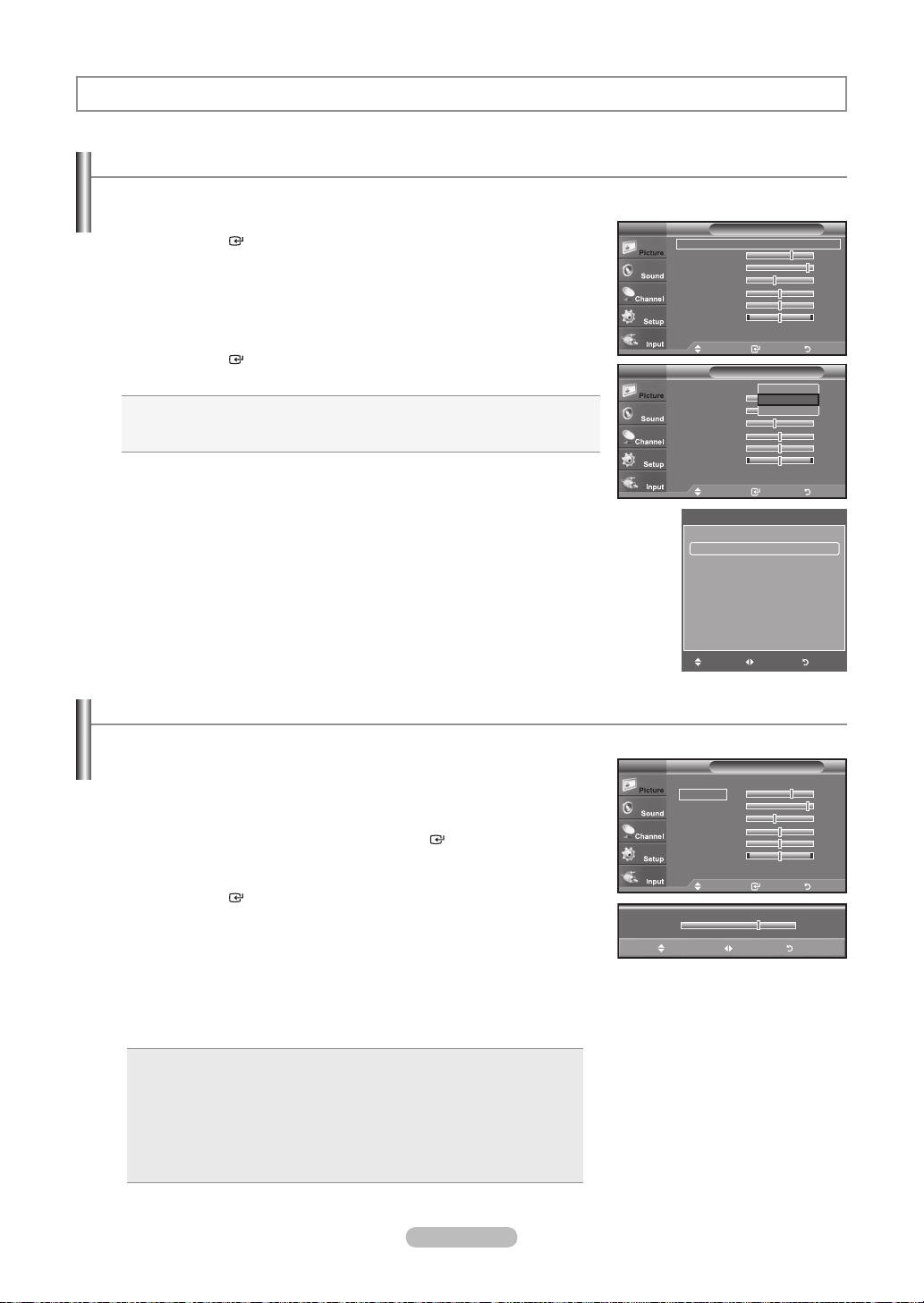
Changing the Picture Standard
You can activate either Dynamic, Standard, Movie by making a selection from the menu.
1. Press the MENU button to display the menu.
Press the ENTER
2. Press the ENTER
Press the ▲ or ▼ button to select the “Dynamic”, “Standard” or “Movie”.
Dynamic: Selects the picture for high-denition in a bright room.
Standard: Selects the picture for the optimum display in a normal environment.
Movie: Selects the picture for viewing movies in a dark room.
button, to select “Picture”.
button to select "Mode".
3. Press the EXIT button to exit.
Easy Setting
Press the TOOLS button on the remote control.
1.
Press the ▲ or ▼ button to select “Picture Mode”.
2.
3. Press the ◄ or ► button to select the required option.
4. Press the EXIT or TOOLS button to exit.
Customizing the Picture Settings
Your television has several setting options that allow you to control the picture quality.
1. To select the desired picture mode, follow the “Changing the Picture Standard”
instructions numbers 1 and 2.
Press the ▲ or ▼ button to select “Backlight”, “Contrast”, “Brightness”,
2.
“Sharpness”, “Color” or “Tint”, then press the ENTER button.
3. Press the ◄ or ► button to decrease or increase the value of a particular item.
Press the ENTER button.
Press the EXIT button to exit.
When you make changes to “Backlight”, “Contrast”, “Brightness”, “Sharpness”,
➣
“Color” or “Tint”, the OSD will be adjusted accordingly.
In PC mode, you can only make changes to “Backlight”, “Contrast” and
➣
“Brightness”.
Settings can be adjusted and stored for each external device you have
➣
connected to an input of the TV.
Mode : Standard ►
Backlight 7
Contrast 95
Brightness 45
Sharpness 50
Color 50
Tint G 50 R 50
▼ More
Move Enter Return
Mode : Dynamic
Backlight 7
Contrast 95
Brightness 45
Sharpness 50
Color 50
Tint G 50 R 50
▼ More
Move Enter Return
Anynet+(HDMI-CEC)
Picture Mode ◄ Standard ►
Sound Mode : Custom
Sleep Timer : Off
Add to Favorite
Switch to Air
Move Adjust Exit
Mode : Standard ►
Backlight 7
Contrast 95
Brightness 45
Sharpness 50
Color 50
Tint G 50 R 50
▼ More
Move Enter Return
▲
Backlight
▼
Move Adjust Return
PictureTV
PictureTV
Tools
PictureTV
Dynamic
Standard
Movie
7
Backlight: Adjusts the brightness of LCD back light.
•
Contrast: Adjusts the contrast level of the picture.
•
Brightness: Adjusts the brightness level of the picture.
•
Sharpness: Adjusts the edge definition of the picture.
•
Color: Adjusts color saturation of the picture.
•
: Adjusts the color tint of the picture.
Tint
•
English - 27
Page 30
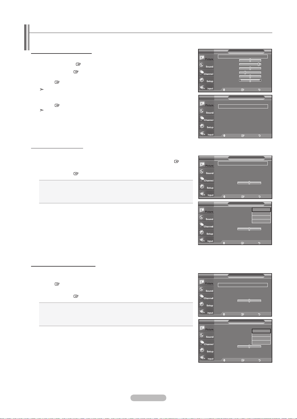
Adjusting the Detailed Settings
Samsung's new TVs allow you to make even more precise picture settings than previous models. See below to adjust detailed
picture settings.
Activating Detailed Settings
1. Press the MENU button to display the menu.
Press the ENTER b utton to select “Picture”.
2. Press the ENTER
Press the ▲ or ▼ button to select "Standard" or "Movie", then press the
button to select “Mode”
ENTER button.
"Detailed Settings" is available in "Standard" or "Movie" mode.
3. Press the ▲ or ▼ button to select “Detailed Settings”, then press the
ENTER button.
In PC mode, you can only make changes to “Dynamic Contrast”, “Gamma” and
“White Balance” from among the “Detailed Settings” items.
Setting the Black adjust
You can select the black level on the screen to adjust the screen depth.
4. Press the ▲ or ▼ button to select “Black adjust”, then press the ENTER
5. Press the ▲ or ▼ button to select “Off”, “Low”, “Medium” or “High”.
Press the ENTER button.
Off: Turns off the black adjustment function.
Low: Sets the black color depth to low.
Medium: Sets the black color depth to medium.
High: Sets the black color depth to high.
button.
Mode : Movie ►
Backlight 5
Contrast 95
Brightness 50
Sharpness 20
Color 50
Tint G 50 R 50
▼ More
▲ More
Detailed Settings ►
Picture Options ►
Reset : OK ►
Black Adjust : Off ►
Dynamic Contrast : Off ►
Gamma : 0 ►
Color Space ►
White Balance ►
Flesh Tone 0
Edge Enhancement : Off ►
Black Adjust : Off
Dynamic Contrast : Off
Gamma : 0
Color Space
White Balance
Flesh Tone 0
Edge Enhancement : Off
PictureTV
Move Enter Return
PictureTV
Move Enter Return
Detailed SettingsTV
Move Enter Return
Detailed SettingsTV
Off
Low
Medium
High
Setting the Dynamic Contrast
You can adjust the screen contrast so that the optimal contrast is provided.
6. Press the ▲ or ▼ button to select “Dynamic Contrast”, then press the
ENTER button.
7. Press the ▲ or ▼ button to select “Off”, “Low”, “Medium” or “High”.
Press the ENTER button.
Off: Turns off the dynamic contrast adjustment function.
Low: Sets the dynamic contrast to low.
Medium: Sets the dynamic contrast to medium.
High: Sets the dynamic contrast to high.
English - 28
Move Enter Return
Detailed SettingsTV
Black Adjust : Off ►
Dynamic Contrast : Off ►
Gamma : 0 ►
Color Space ►
White Balance ►
Flesh Tone 0
Edge Enhancement : Off ►
Move Enter Return
Detailed SettingsTV
Black Adjust : Off
Dynamic Contrast : Off
Gamma : 0
Color Space
White Balance
Flesh Tone 0
Edge Enhancement : Off
Move Enter Return
Off
Low
Medium
High
Page 31

Adjusting the Gamma
You can adjust the Primary Color (Red, Green, Blue) Intensity. (-3 ~ +3)
8. Press the ▲ or ▼ button to select “Gamma”, then press the ENTER
9. Press the ◄ or ► button to decrease or increase the value.
Press the ENTER button.
button.
Detailed SettingsTV
Black Adjust : Off ►
Dynamic Contrast : Off ►
Gamma : 0 ►
Color Space ►
White Balance ►
Flesh Tone 0
Edge Enhancement : Off ►
Move Enter Return
Setting the Color Space
Color space is a color matrix composed of red, green and blue colors.
Select your favorite color space to experience the most natural color.
10.
Press the ▲ or ▼ button to select “Color Space”, then press the ENTER button.
Press the ENTER button again to select “Color Space”.
11.
Press the ▲ or ▼ button to select “Auto”, “Native” or “Custom”.
12.
Press the ENTER button.
Auto: Auto Color Space automatically adjusts to the most natural color
•
tone based on program sources.
Native: Native Color Space offers deep and rich color tone.
•
: Adjusts the color range to suit your preference.
Custom
•
(see “Customizing the Color Space”)
Customizing the Color Space
13. Press the ▲ or ▼ button to select “Color”, then press the ENTER button.
“Color” is available when “Color Space” is set to “Custom”.
➣
Press the ▲ or ▼ button to select “Red”, “Green”, “Blue”, “Yellow”, “Cyan” or
14.
“Magenta”. Press the ENTER button.
15.
Press the ▲ or ▼ button to select “Red”, “Green” or “Blue” to change it.
Press the ENTER button.
Press the ◄ or ► button to decrease or increase the value of a particular item.
16.
Press the ENTER button.
➣
In “Color”, you can adjust the RGB values for the selected color.
➣
To reset the adjusted RGB value, select “Reset”.
Red: Adjusts the red saturation level of the selected color.
•
Green: Adjusts the green saturation level of the selected color.
•
Blue: Adjusts the blue saturation level of the selected color.
•
Reset: Resets the color space to the default values.
•
Changing the adjustment value will refresh the adjusted screen.
➣
Settings can be adjusted and stored for each external device you have
➣
connected to an input of the TV. For example, if you have a DVD player
connected to HDMI 1 and it is currently selected, settings and adjustments will
be saved for the DVD player.
Gamma
Adjust Return
Detailed SettingsTV
Black Adjust : Off ►
Dynamic Contrast : Off ►
Gamma : 0 ►
Color Space ►
White Balance ►
Flesh Tone 0
Edge Enhancement : Off ►
Move Enter Return
Color Space : Auto
Color : Red
Red 50
Green 0
Blue 0
Reset
Color Space : Custom
Color : Red
Red 50
Green 0
Blue 0
Reset
Color Space : Custom
Color : Red
Red 50
Green 0
Blue 0
Reset
▲
Red
▼
Move Adjust Return
Color SpaceTV
Move Enter Return
Color SpaceTV
Move Enter Return
Color SpaceTV
Move Enter Return
Auto
Native
Custom
Red
Green
Blue
Yellow
Cyan
Magenta
0
50
English - 29
Page 32

Adjusting the White Balance
You can adjust the color temperature for more natural picture colors.
17. Press the ▲ or ▼ button to select “White Balance”, then press the ENTER
button.
18. Select the required option by pressing the ▲ or ▼ button, then press the
ENTER button.
19. Press the ◄ or ► button to decrease or increase the value of a particular item.
Press the ENTER button.
R-Offset: Adjusts the red color darkness.
G-Offset: Adjusts the green color darkness.
B-Offset: Adjusts the blue color darkness.
R-Gain: Adjusts the red color brightness.
G-Gain: Adjusts the green color brightness.
B-Gain: Adjusts the blue color brightness.
The previously adjusted white balance will be reset to the factory defaults.
Reset:
Changing the adjustment value will refresh the adjusted screen.
Detailed SettingsTV
Black Adjust : Off ►
Dynamic Contrast : Off ►
Gamma : 0 ►
Color Space ►
White Balance ►
Flesh Tone 0
Edge Enhancement : Off ►
Move Enter Return
White BalanceTV
R-Offset 25
G-Offset 25
B-Offset 25
R-Gain 25
G-Gain 25
B-Gain 25
Reset
Move Enter Return
▲
R-Offset
▼
Move Adjust Return
25
Adjusting the Flesh Tone
You can emphasize the pink ‘flesh tone’ in the picture.
20. Press the ▲ or ▼ button to select “Flesh Tone”, then press the ENTER
button.
21. Press the ◄ or ► button to decrease or increase the value.
Press the ENTER button.
Changing the adjustment value will refresh the adjusted screen.
Setting the Edge Enhancement
You can emphasize object boundaries in the picture.
22. Press the ▲ or ▼ button to select “Edge Enhancement”, then press the
ENTER button.
23. Press the ▲ or ▼ button to select “Off” or “On”.
Press the ENTER button.
Press the EXIT button to exit.
Detailed SettingsTV
Black Adjust : Off ►
Dynamic Contrast : Off ►
Gamma : 0 ►
Color Space ►
White Balance ►
Flesh Tone 0
Edge Enhancement : Off ►
Move Enter Return
Flesh Tone
Adjust Return
Detailed SettingsTV
Black Adjust : Off ►
Dynamic Contrast : Off ►
Gamma : 0 ►
Color Space ►
White Balance ►
Flesh Tone 0
Edge Enhancement : Off ►
Move Enter Return
Detailed SettingsTV
Black Adjust : Off
Dynamic Contrast : Off
Gamma : 0
Color Space
White Balance
Flesh Tone 0
Edge Enhancement : Off ►
Move Enter Return
0
Off
On
English - 30
Page 33

Conguring Picture Options
Activating Picture Options
1. Press the MENU button to display the menu.
Press the ENTER button, to select “Picture”.
2. Press the ▲ or ▼ button to select "Picture Options", then press the
ENTER
Press the ▲ or ▼ button to select a particular item. Press the ENTER button.
When you are satisfied with your setting, press the ENTER button.
In PC mode, you can only make changes to the “Color Tone” and “Size” from
button.
among the items in “Picture Options”.
▲ More
Detailed Settings ►
Picture Options ►
Reset : OK ►
PictureTV
Move Enter Return
Setting the Color Tone
1. Follow the “Activating Picture Options” instructions numbers 1 and 2. (Refer to
page 31)
2. Press the ▲ or ▼ button to select “Color Tone”, then press the ENTER
button.
3. Press the ▲ or ▼ button to select “Cool2”, “Cool1”, “Normal”, “Warm1” or “Warm2”.
Press the ENTER button.
“Warm1” or “Warm2” is only activated when the picture mode is “Movie”.
Settings can be adjusted and stored for each external device you have connected
to an input of the TV.
Setting the Screen Size
Occasionally, you may want to change the size of the image on your screen. Your TV
comes with six screen size options, each designed to work best with specific types of
video input. Your cable box or satellite receiver may have its own set of screen sizes as
well. In general, though, you should view the TV in 16:9 mode as much as possible.
1. Follow the “Activating Picture Options” instructions numbers 1 and 2.
(Refer to page 31)
Press the ▲ or ▼ button to select “Size”, then press the ENTER button.
2.
Press the ▲ or ▼ button to select the screen format you want.
3.
Press the ENTER button.
Press the EXIT button to exit.
16:9 : Sets the picture to 16:9 wide mode.
•
Zoom1: Magnifies the size of the picture on the screen.
•
Zoom2: Magnifies the size of the picture more than “Zoom1”.
•
Wide Fit: Enlarges the aspect ratio of the picture to fit the entire screen.
•
4:3 : Sets the picture to 4:3 normal mode.
•
Just Scan
•
: Use the function to see the full image without any cutoff when
HDMI (720p/1080i), Component (1080i) or DTV (1080i) signals
are input.
Picture OptionsTV
Color Tone : Normal ►
Size : 16:9 ►
Digital NR : Auto ►
DNle : Off ►
HDMI Black Level : Normal ►
Film Mode : Off ►
Blue Only Mode : Off ►
Move Enter Return
Picture OptionsTV
Color Tone : Cool1
Size : 16:9
Digital NR : Auto
DNle : On
HDMI Black Level : Normal
Film Mode : Off
Blue Only Mode : Off
Move Enter Return
Color Tone : Normal ►
Size : 16:9 ►
Digital NR : Auto ►
DNle : Off ►
HDMI Black Level : Normal ►
Film Mode : Off ►
Blue Only Mode : Off ►
Move Enter Return
16 : 9
Zoom1
Zoom2
Wide Fit
4 : 3
Just Scan
Move Enter Return
Cool2
Cool1
Normal
Warm1
Warm2
Picture OptionsTV
SizeTV
English - 31
Page 34

Temporary image retention may occur when viewing a static image on the set
➣
for more than two hours.
After selecting “Zoom1”, “Zoom2” or “Wide Fit”:
➣
Press the ◄ or ► button to select “Position”, then press the ENTER
button. Press the ▲ or ▼ button to move the picture up and down.
Reset: Press the ◄ or ► button to select “Reset”, then press the ENTER
button. You can initialize the setting.
After selecting “Just Scan” in HDMI (1080i) or Component (1080i) mode:
➣
Press the ▲ or ▼ button to select “H-Position” or “V-Position”, then press the
ENTER
Press the ◄ or ► button to adjust the screen Position. Press the
button.
ENTER button.
Reset: Press the ▲ or ▼ button to select “Reset”, then press the ENTER
button. You can initialize the setting.
HD (High Definition)
➣
16:9 - 1080i (1920x1080), 720p (1280x720)
Settings can be adjusted and stored for each external device you have
➣
connected to an input of the TV.
Input Source Picture Size
TV, Video, S-Video,
16:9, Zoom1, Zoom2, 4:3
Component (480i, 480p)
DTV(1080i), Component (1080i), HDMI
16:9, 4:3, Wide Fit, Just Scan
(720p, 1080i)
PC 16:9, 4:3
Alternately, you can press the P.SIZE button on the remote control repeatedly to
O
change the picture size.
16 : 9
Zoom1
Zoom2
Wide Fit
4 : 3
Just Scan
16 : 9
Zoom1
Zoom2
Wide Fit
4 : 3
Just Scan ►
H-Position 0
V-Position 0
Reset
SizeTV
Position Reset
Adjust Enter Return
SizeTV
Move Enter Return
Just ScanTV
Move Enter Return
16:9
16:9
Sets the picture to 16:9 wide mode.
Wide Fit U Move
Wide Fit
Enlarges the aspect ratio of the picture
to fit the entire screen.
Zoom1 U Move Zoom2 U Move
Zoom1
Magnifies the size of the picture on the
screen.
4:3 Just Scan
4:3
Sets the picture to 4:3 normal mode.
English - 32
Zoom2
Magnifies the size of the picture more
than “Zoom1”.
Just Scan
Use the function to see the full
image without any cutoff when HDMI
(720p/1080i), Component (1080i) or
DTV (1080i) signals are input.
Page 35

Setting the Digital Noise Reduction
If the broadcast signal received by your TV is weak, you can activate the Digital Noise
Reduction feature to help reduce any static and ghosting that may appear on the screen.
1. Follow the “Activating Picture Options” instructions numbers 1 and 2.
(Refer to page 31)
Press the ▲ or ▼ button to select "Digital NR", then press the ENTER button.
2.
3.
Press the ▲ or ▼ button to select "Off", "Low", "Medium", "High" or "Auto".
Press the ENTER button.
Off: Turns the screen noise reduction function off.
Low: Reduces screen noise at a low level.
Medium: Reduces screen noise at a medium level.
High: Reduces screen noise at a high level.
Auto: Automatically recognizes and reduces screen noise.
Press the EXIT button to exit.
Picture OptionsTV
Color Tone : Normal ►
Size : 16:9 ►
Digital NR : Auto ►
DNle : Off ►
HDMI Black Level : Normal ►
Film Mode : Off ►
Blue Only Mode : Off ►
Move Enter Return
Picture OptionsTV
Color Tone : Normal
Size : 16:9
Digital NR : Auto
DNle : On
HDMI Black Level : Normal
Film Mode : Off
Blue Only Mode : Off
Move Enter Return
Off
Low
Medium
High
Auto
Setting the DNIe (Digital Natural Image engine)
This TV includes the DNIe function to provide high visual quality. If you set DNIe to on,
you can view the screen with the DNIe feature activated.
1. Follow the “Activating Picture Options” instructions numbers 1 and 2.
(Refer to page 31)
2. Press the ▲ or ▼ button to select "DNIe", then press the ENTER
3. Press the ▲ or ▼ button to select "Off" or "On", then press the ENTER
button.
button.
• Off: Switches off the "DNIe" mode.
• On: Switches on the "DNIe" mode.
Press the EXIT button to exit.
➣
DNIe™ (Digital Natural Image engine)
This feature brings you a more detailed image with 3D noise reduction and
detail, contrast and white enhancement.
“DNIe” is only available in “Dynamic” mode.
➣
Setting the HDMI Black Level
You can select the black level on the screen to adjust the screen depth.
1. Follow the “Activating Picture Options” instructions numbers 1 and 2.
(Refer to page 31)
2. Press the
▲ or ▼
button to select “HDMI Black Level”, then
press the ENTER button.
▲ or ▼
3. Press the
button to select “Normal” or “Low”, then press
the ENTER button.
• Normal: The screen gets brighter.
• Low: The screen gets darker.
➣
This function is active only when an external device is connected to the TV via
HDMI. “HDMI Black Level” function may not be compatible with all external
devices.
Press the EXIT button to exit.
Color Tone : Cool1 ►
Size : 16:9 ►
Digital NR : Auto ►
DNle : On ►
HDMI Black Level : Normal ►
Film Mode : Off ►
Blue Only Mode : Off ►
Move Enter Return
Color Tone : Cool1
Size : 16:9
Digital NR : Auto
DNle : On
HDMI Black Level : Normal
Film Mode : Off
Blue Only Mode : Off
Move Enter Return
TV
Color Tone : Normal ►
Size : 16:9 ►
Digital NR : Auto ►
DNle : Off ►
HDMI Black Level : Low ►
Film Mode : Off ►
Blue Only Mode : Off ►
Move Enter Return
TV
Color Tone : Normal
Size : 16:9
Digital NR : Auto
DNle : Off
HDMI Black Level : Normal
Film Mode : Off
Blue Only Mode : Off
Move Enter Return
Picture OptionsTV
Picture OptionsTV
Off
On
Picture Options
Picture Options
Normal
Low
English - 33
Page 36

Setting the Film Mode
The TV can be set to automatically sense and process lm signals from all sources and
adjust the picture for optimum quality.
1. Follow the “Activating Picture Options” instructions numbers 1 and 2.
(Refer to page 31)
2. Press the ▲ or ▼ button to select "Film Mode", then press the ENTER
button.
TV
Color Tone : Normal ►
Size : 16:9 ►
Digital NR : Auto ►
DNle : Off ►
HDMI Black Level : Normal ►
Film Mode : Off ►
Blue Only Mode : Off ►
Move Enter Return
Picture Options
3. Press the ▲ or ▼ button to select "Off" or "Auto", then press the ENTER
Press the
EXIT button to exit.
button.
" Film mode" is supported in TV, VIDEO, S-VIDEO, COMPONENT(480i / 1080i)
and HDMI(480i / 1080i).
Setting the Blue Only Mode
This function is for AV device measurement experts. This function displays the blue
signal only by removing the red and green signals from the video signal so as to provide
a Blue Filter effect that is used to adjust the Color and Tint of video equipment such as
DVD players, Home Theaters, etc.
Using this function, you can adjust the Color and Tint to preferred values appropriate to
the signal level of each video device using the Red/Green/Blue/ Cyan/Magenta/Yellow
Color Bar Patterns, without using an additional Blue Filter.
1. Follow the “Activating Picture Options” instructions numbers 1 and 2.
(Refer to page 31).
2. Press the ▲ or ▼ button to select "Blue Only Mode", then press the ENTER
button.
3. Press the ▲ or ▼ button to select "Off" or "On", then press the ENTER
Press the
EXIT button to exit.
button.
“Blue Only Mode” is available when the picture mode is set to “Movie” or
“Standard”.
TV
Color Tone : Normal
Size : 16:9
Digital NR : Auto
DNle : Off
HDMI Black Level : Normal
Film Mode : Off
Blue Only Mode : Off
Move Enter Return
TV
Color Tone : Normal ►
Size : 16:9 ►
Digital NR : Auto ►
DNle : Off ►
HDMI Black Level : Normal ►
Film Mode : Off ►
Blue Only Mode : Off ►
Move Enter Return
TV
Color Tone : Normal
Size : 16:9
Digital NR : Auto
DNle : Off
HDMI Black Level : Normal
Film Mode : Off
Blue Only Mode : Off
Move Enter Return
Picture Options
Off
Auto
Picture Options
Picture Options
Off
On
Resetting the Picture Settings to the Factory Defaults
1. Press the MENU button to display the menu.
Press the ENTER
2.
Press the ▲ or ▼ button to select "Reset", then press the ENTER
Press the ▲ or ▼ button to select “OK” or “Cancel” then press the ENTER
button.
Press the EXIT button to exit.
Each mode can be reset.
button, to select “Picture”.
English - 34
button.
▲ More
Detailed Settings
Picture Options
Reset : OK
PictureTV
OK
Cancel
Move Enter Return
Page 37

Sound Control
Changing the Sound Standard
You can select the sound mode to best suit the programming you’re watching.
1. Press the MENU button to display the menu.
Press the
▲ or ▼
button to select "Sound", then press the ENTER
button.
2. Press the ENTER button to select "Mode".
Press the ▲ or ▼ button to select “Standard”, “Music”, “Movie”, “Speech”, or
“Custom” sound setting, then press the ENTER button.
Press the EXIT button to exit.
• Standard: selects the normal sound mode.
• Music: emphasizes music over voices.
• Movie: provides the best sound for movies
• Speech: emphasizes voice over other sounds.
• Custom: recalls your customized sound settings.
(see “Customizing the Sound”)
Easy Setting
1.
Press the TOOLS button on the remote control.
Press the ▲ or ▼ button to select “Sound Mode”.
2.
3. Press the ◄ or ►button to select the required option.
4. Press the EXIT or TOOLS button to exit.
Mode : Custom ►
Equalizer ►
SRS TruSurround XT : Off ►
Multi-Track Options ►
Auto Volume : Off ►
TV Speaker : On ►
Mode : Custom
Equalizer
SRS TruSurround XT : Off
Multi-Track Options
Auto Volume : Off
TV Speaker : On
Anynet+(HDMI-CEC)
Picture Mode : Standard
Sound Mode ◄ Custom ►
Sleep Timer : Off
Add to Favorite
Switch to Air
Move Adjust Exit
SoundTV
Move Enter Return
SoundTV
Standard
Music
Movie
Speech
Custom
Move Enter Return
Tools
Customizing the Sound
The sound settings can be adjusted to suit your personal preference.
1. Press the MENU button to display the menu.
Press the ▲ or ▼ button to select "Sound", then press the ENTER
2. Press the ▲ or ▼ button to select "Equalizer", then press the ENTER
3. Press the ◄ or ► button to select a particular frequency to adjust.
Press the ▲ or ▼ button to increase or decrease the level of the particular frequency.
Press the ENTER
button.
Press the EXIT button to exit.
• L/R Sound Balance Adjustment: To adjust the sound balance of the L/R
speakers.
• Bandwidth Adjustment (100Hz, 300Hz, 1KHz, 3KHz, 10KHz): To adjust the
level of different bandwidth frequencies.
If you make any changes to the "Equalizer" settings, the sound mode is
automatically switched to the "Custom" mode.
English - 35
button.
button.
Mode : Custom ►
Equalizer ►
SRS TruSurround XT : Off ►
Multi-Track Options ►
Auto Volume : Off ►
TV Speaker : On ►
R
L
Move Adjust Return
SoundTV
Move Enter Return
EqualizerTV
+
0
-
100Hz
300Hz 1KHz 3KHz 10KHzBalance
Page 38

Setting the TruSurround XT
TruSurround XT is a patented SRS technology that solves the problem of playing 5.1 multichannel content over two speakers.
TruSurround delivers a compelling, virtual surround sound experience through any two-speaker playback system, including internal
television speakers. It is fully compatible with all multichannel formats.
1. Press the MENU button to display the menu.
Press the ▲ or ▼ button to select "Sound", then press the ENTER
button.
2. Press the ▲ or ▼ button to select "SRS TruSurround XT", then press the
ENTER
3. Press the ▲ or ▼ button to select "Off" or "On", then press the ENTER
button.
Press the EXIT button to exit.
TruSurround XT, SRS and Symbol are trademarks of
SRS Labs, Inc.
button.
Mode : Custom ►
Equalizer ►
SRS TruSurround XT : Off ►
Multi-Track Options ►
Auto Volume : Off ►
TV Speaker : On ►
Mode : Custom
Equalizer
SRS TruSurround XT : Off
Multi-Track Options
Auto Volume : Off
TV Speaker : On
SoundTV
Move Enter Return
SoundTV
Off
On
TruSurround XT technology is incorporated under license
from SRS Labs, Inc.
Press the SRS button on the remote control to select "Off" or "On".
Move Enter Return
Choosing a Multi-Channel Sound (MTS) track - Digital
The digital-TV transmission system is capable of simultaneous transmission of many audio tracks (for example, simultaneous
translations of the program into foreign languages). The availability of these additional “multitracks” depends upon the program.
"Multi-Track Options" is available only in TV mode.
Preferred Language
SoundTV
Move Enter Return
Multi-Track OptionsTV
: English ►
►
Multi-Track OptionsTV
: English
English
Spanish
French
1. Press the MENU button to display the menu.
Press the ▲ or ▼ button to select "Sound", then press the ENTER
button.
Quick way to access the MTS menu: Just press the “MTS” button on the remote
control. You can listen in a language other than your chosen language by
pressing the MTS button.
2. Press the ▲ or ▼ button to select “Multi-Track Options", then press the ENTER
button.
3. Press the ENTER
Press the ▲ or ▼ button to choose the language (English, Spanish or French) you
button to select “Preferred Language”.
want, then press the ENTER button.
Press the EXIT button to exit.
“Preferred Language” is available only in Digital TV mode.
You can only select the language from among the actual languages being broadcast.
Mode : Custom ►
Equalizer ►
SRS TruSurround XT : Off ►
Multi-Track Options ►
Auto Volume : Off ►
TV Speaker : On ►
Preferred Language
Multi-Track Sound : Stereo
Enter Return
Preferred Language
Multi-Track Sound : Stereo
You can listen in a language other than the Preferred language by pressing
the MTS button on the remote control.
English - 36
Move Enter Return
Page 39

Choosing a Multi-Channel Sound (MTS) track - Analog
Multi-Track Sound
1. Press the MENU button to display the menu.
Press the ▲ or ▼ button to select "Sound", then press the ENTER
2. Press the ▲ or ▼ button to select "Multi-Track Options", then press the
ENTER
button.
3. Press the ▲ or ▼ button to select “Multi-Track Sound”, then press the ENTER
button.
Press the ▲ or ▼ button to select a setting you want, then press the ENTER
button.
Press the EXIT button to exit.
• Mono: Choose for channels that are broadcasting in mono or if you are having
difficulty receiving a stereo signal.
• Stereo: Choose for channels that are broadcasting in stereo.
• SAP: Choose to listen to the Separate Audio Program, which is usually a
foreign-language translation.
“Multi-Track Sound” is available only in Analog TV mode.
Depending on the particular program being broadcast, you can listen to “Mono”,
“Stereo” or “SAP”.
Press the MTS buttons on the remote control repeatedly to select “Mono”,
“Stereo” or “SAP”.
button.
Multi-Track OptionsTV
Preferred Language
Multi-Track Sound : Stereo
Enter Return
Preferred Language
Multi-Track Sound : Stereo
: English ►
►
Multi-Track OptionsTV
: English
Mono
Stereo
SAP
Move Enter Return
Automatic Volume Control
Reduces the differences in volume level among broadcasters.
1. Press the MENU button to display the menu.
Press the ▲ or ▼ button to select "Sound", then press the ENTER
2. Press the ▲ or ▼ button to select "Auto Volume", then press the ENTER
3. Press the ▲ or ▼ button to set Auto Volume "Off" or "On" then press the
ENTER
button.
Press the EXIT button to exit.
English - 37
button.
button.
Mode : Custom ►
Equalizer ►
SRS TruSurround XT : Off ►
Multi-Track Options ►
Auto Volume : Off ►
TV Speaker : On ►
Mode : Custom
Equalizer
SRS TruSurround XT : Off
Multi-Track Options
Auto Volume : Off
TV Speaker : On
SoundTV
Move Enter Return
SoundTV
Off
On
Move Enter Return
Page 40

Setting the TV Speakers On/Off
Sound output from the TV speakers is muted.
1. Press the MENU button to display the menu.
Press the ▲ or ▼ button to select "Sound", then press the ENTER
2. Press the ▲ or ▼ button to select "TV Speaker", then press the ENTER
3. Press the ▲ or ▼ button to select “Off”, then press the ENTER
button.
button.
button.
Press the EXIT button to exit.
When “TV Speaker” is set to “Off”, Sound menus except “Multi-Track Options”
cannot be adjusted.
The VOL , VOL and MUTE buttons do not operate when the "TV Speaker"
is set to “Off”.
TV’s Internal Speakers Audio Out (Optical, L/R Out) to Sound System
TV Speaker On
TV Speaker Off
Video No Signal
RF AV, S-Video
Speaker Output Speaker Output Speaker Output Sound Output Sound Output Sound Output
Mute Mute Mute Sound Output Sound Output Sound Output
Mute Mute Mute Mute Mute Mute
Component, PC, HDMI
RF AV, S-Video
Manufactured under license from Dolby Laboratories. Dolby and the double-D symbol are trademarks
of Dolby Laboratories.
Mode : Custom ►
Equalizer ►
SRS TruSurround XT : Off ►
Multi-Track Options ►
Auto Volume : Off ►
TV Speaker : On ►
Mode : Custom
Equalizer
SRS TruSurround XT : Off
Multi-Track Options
Auto Volume : Off
TV Speaker : On
SoundTV
Move Enter Return
SoundTV
Off
On
Move Enter Return
Component, PC, HDMI
Connecting Headphones (Sold separately)
You can connect a set of headphones to your set if you wish to watch a TV program without disturbing other people in the room.
When you insert the headphone’s plug into the headphone jack, you cannot operate
TV Speaker
“
” in Sound menu.
Prolonged use of headphones at a high volume may damage your hearing.
You will not hear sound from the speakers when you connect headphones to the TV.
TV Side Panel
English - 38
Page 41

Channel Control
Clearing Scrambled Channels - Digital
The Clear Scrambled Channel function is used to lter out scrambled channels after Auto Program is completed.
This process may take up to 20~30 minutes.
1. Press the MENU button to display the menu.
Press the ▲ or ▼ button to select "Channel", then press the ENTER
2.
Press the ▲ or ▼ button to select "Clear Scrambled Channel", then press the
ENTER button.
It searches scrambled channels, which are to be removed from the list.
To stop searching scrambled channels:
Press the ENTER button to select Stop.
Press the ◄ button to select "Yes", then press the ENTER button.
3. When the scrambled channel searching is completed, press the ENTER
button.
Press the EXIT button to exit.
This function is only available in “Cable” mode.
button.
TV
Antenna : Cable ►
Auto Program ►
Clear Scrambled Channel ►
Channel List ►
Name ►
Fine Tune ►
Signal Strength ►
Clear Scrambled Channel
Removing scrambled channel.
Enter Return
Channel
Move Enter Return
Auto Program
Plug & Play
DTV Cable 40
30 %
Stop
English - 39
Page 42

Adding and Erasing Channels
Using this menu, you can Add/Delete or set Favorite channels and use the program guide for digital broadcasts.
To use the Channel List function, rst run “Auto Program” (see page 25).
1. Press the MENU button to display the menu.
Press the ▲ or ▼ button to select "Channel", then press the ENTER
2. Press the ▲ or ▼ button to select "Channel List", then press the ENTER
button.
3. Press the ENTER
button to select “All”.
button.
4. Press the ◄, ►, ▲ or ▼ button to select a channel to delete, then press the
ENTER button.
Press the ▲ or ▼ button to select “Delete”, then press the ENTER button to
delete the channel.
The mark will disappear.
5. Press the ◄, ►, ▲ or ▼ button to select a channel to add, then press the
ENTER button.
Press the ▲ or ▼ button to select “Add”, then press the ENTER button to
add the channel.
The mark will appear and the channel will be added.
Press the EXIT button to exit.
All selected channels will be shown on “Added" menu.
• Red button: Press repeatedly to select “All”, “Added” or “Favorite”.
• Green button: Press to add all deleted channels.
• Yellow button: Press to delete all memorized channels.
TV
Antenna : Cable ►
Auto Program ►
Clear Scrambled Channel ►
Channel List ►
Name ►
Fine Tune ►
Signal Strength ►
Move Enter Return
TV
All ►
Added
Favorite ►
Default List Mode : All ►
Air 5 1 / 2
DTV Air 2-1
Air3
Air4
Air 5
Air 6
Air 7
DTV Air 7-1
Air 8
List Mode Delete AllAdd All
Move Enter Return
Air 5 1 / 2
DTV Air 2-1
Air3
Air4
Air 5
Air 6
Air 7
DTV Air 7-1
Air 8
List Mode
Move Enter Page Return
Air 5 1 / 2
DTV Air 2-1
Air3
Air4
Air 5
Air 6
Air 7
DTV Air 7-1
Air 8
List Mode
Move Enter Return
Air 5 1 / 2
DTV Air 2-1
Air3
Air4
Air 5
Air 6
Air 7
DTV Air 7-1
Air 8
List Mode
Move Enter Page Return
Channel List / All
Air 9
Air 10
DTV Air 10-1
DTV Air 10-2
Watch
Add
DTV Air 10-3
Delete
DTV Air 10-1
Favorite
DTV Air 10-2
DTV Air 10-3
Channel List / All
Air 9
Air 10
DTV Air 10-1
DTV Air 10-2
DTV Air 10-3
DTV Air 10-1
DTV Air 10-2
DTV Air 10-3
Channel List / All
Air 9
Air 10
DTV Air 10-1
Watch
DTV Air 10-2
Add
DTV Air 10-3
Delete
DTV Air 10-1
Favorite
DTV Air 10-2
DTV Air 10-3
Channel List / All
Air 9
Air 10
DTV Air 10-1
DTV Air 10-2
DTV Air 10-3
DTV Air 10-1
DTV Air 10-2
DTV Air 10-3
Channel List
►
Move Enter Return
Channel
DTV Air 10-1
DTV Air 10-2
DTV Air 10-3
Air 12
DTV Air 13-1
DTV Air 13-2
DTV Air 13-3
DTV Air 13-4
DTV Air 10-1
DTV Air 10-2
DTV Air 10-3
Air 12
DTV Air 13-1
DTV Air 13-2
DTV Air 13-3
DTV Air 13-4
Delete AllAdd All
DTV Air 10-1
DTV Air 10-2
DTV Air 10-3
Air 12
DTV Air 13-1
DTV Air 13-2
DTV Air 13-3
DTV Air 13-4
Delete AllAdd All
DTV Air 10-1
DTV Air 10-2
DTV Air 10-3
Air 12
DTV Air 13-1
DTV Air 13-2
DTV Air 13-3
DTV Air 13-4
Delete AllAdd All
English - 40
Page 43

To Set-Up Your Favorite Channels
You can set channels you watch frequently as favorites.
1. Press the MENU button to display the menu.
Press the ▲ or ▼ button to select "Channel", then press the ENTER
2. Press the ▲ or ▼ button to select "Channel List", then press the ENTER
3. Press the ▲ or ▼ button to select "All" or "Added", then press the ENTER
4. Press the ◄, ►, ▲ or ▼ button to select your favorite channels to watch
among the labeled channels. Then press the ENTER button.
Press the ▲ or ▼ button to select “Favorite”, then press the ENTER button.
The " " symbol will be highlighted and the channel will be set as a Favorite.
To cancel your Favorite channel selection, press the ENTER button until the
" " symbol is no longer highlighted.
Press the EXIT button to exit.
Only memorized channels can be set as favorite channels.
All favorite channels will be shown in the “Favorite” menu.
button.
TV
button.
button.
Air 5 1 / 2
DTV Air 2-1
Air3
Air4
Air 5
Air 6
Air 7
DTV Air 7-1
Air 8
List Mode Delete All
Move Enter Return
Air 5 1 / 2
DTV Air 2-1
Air3
Air4
Air 5
Air 6
Air 7
DTV Air 7-1
Air 8
List Mode
Move Enter Page Return
Antenna : Cable ►
Auto Program ►
Clear Scrambled Channel ►
Channel List ►
Name ►
Fine Tune ►
Signal Strength ►
TV
All ►
Added ►
Favorite ►
Default List Mode : All ►
Channel List / Added
Air 9
Air 10
DTV Air 10-1
DTV Air 10-2
Watch
Add
DTV Air 10-3
Delete
DTV Air 10-1
Favorite
DTV Air 10-2
DTV Air 10-3
Channel List / Added
Air 9
Air 10
DTV Air 10-1
DTV Air 10-2
DTV Air 10-3
DTV Air 10-1
DTV Air 10-2
DTV Air 10-3
Channel
Move Enter Return
Channel List
Move Enter Return
DTV Air 10-1
DTV Air 10-2
DTV Air 10-3
Air 12
DTV Air 13-1
DTV Air 13-2
DTV Air 13-3
DTV Air 13-4
DTV Air 10-1
DTV Air 10-2
DTV Air 10-3
Air 12
DTV Air 13-1
DTV Air 13-2
DTV Air 13-3
DTV Air 13-4
Delete All
To select the favorite channels you have set up, press the FAV.CH button
on the remote control.
Easy Setting
1. Press the TOOLS button on the remote control.
Press the ▲ or ▼ button to select “Add to Favorite” (or “Delete from Favorite”), then press the
2.
ENTER button.
The current channel is added to (or deleted from) Favorites.
English - 41
Tools
Anynet+(HDMI-CEC)
Picture Mode : Standard
Sound Mode : Custom
Sleep Timer : Off
Add to Favorite
Switch to Air
Move Enter Exit
Page 44

Using the Channel Lists - Analog
Displays the channel list automatically when you press CH LIST button on the remote. (Choose “All”, “Added” or “Favorite”)
1. Press the MENU button to display the menu.
Press the ▲ or ▼ button to select "Channel", then press the ENTER
2. Press the ▲ or ▼ button to select "Channel List", then press the
ENTER
Press the ▲ or ▼ button to select “Default List Mode” (the channel list you want to
3.
button.
appear when you press CH LIST), then press the ENTER button.
Press the ▲ or ▼ button to select “All”, “Added” or “Favorite” then press the
ENTER button.
The Channel list you have chosen will now be set.
Press the EXIT button to exit.
Alternately, press the CH LIST button on the remote control to bring up the
button.
TV
Antenna : Air ►
Auto Program ►
Clear Scrambled Channel ►
Channel List ►
Name ►
Fine Tune ►
Signal Strength ►
TV
All
Added
Favorite
Default List Mode : All ►
Channel
Move Enter Return
Channel List
All
Added
Favorite
Move Enter Return
Channel Lists.
Viewing the Channel Lists
You can display a list of all channels, added channels or your favorite channels.
1. Press the MENU button to display the menu.
Press the ▲ or ▼ button to select "Channel", then press the ENTER
button.
2. Press the ▲ or ▼ button to select "Channel List", then press the
ENTER
button.
3. Press the ▲ or ▼ button to select “All”, “Added” or “Favorite”, then press the
ENTER button.
4. Press the ▲ or ▼ button to select “Channel”, then press the ENTER
To toggle between your all channels, add channels or favorite channels,
button.
use the Red button on the remote control.
• Red button: Press repeatedly to select “All”, “Added” or “Favorite”
TV
Antenna : Cable ►
Auto Program ►
Clear Scrambled Channel ►
Channel List ►
Name ►
Fine Tune ►
Signal Strength ►
TV
All ►
Added ►
Favorite ►
Default List Mode : All ►
Air 5 1 / 2
DTV Air 2-1
Air3
Air4
Air 5
Air 6
Air 7
DTV Air 7-1
Air 8
List Mode Delete AllAdd All
Move Enter Page Return
Channel List / All
Air 9
Air 10
DTV Air 10-1
DTV Air 10-2
DTV Air 10-3
DTV Air 10-1
DTV Air 10-2
DTV Air 10-3
Channel
Move Enter Return
Channel List
Move Enter Return
DTV Air 10-1
DTV Air 10-2
DTV Air 10-3
Air 12
DTV Air 13-1
DTV Air 13-2
DTV Air 13-3
DTV Air 13-4
English - 42
Page 45

Labeling Channels
Channels can be labeled so that their call letters appear whenever the channel is selected.labeled so that their call letters appear whenever the channel is selected.o that their call letters appear whenever the channel is selected.
1. Press the MENU button to display the menu.
Press the ▲ or ▼ button to select “Channel”, then press the ENTER button.
Press the ▲ or ▼ button to select “Name”, then press the ENTER button.
2. Press the ▲ or ▼ button to select the channel to be assigned a new name,
then press the ENTER button.
Press the ▲ or ▼ button to select a letter, a number or a blank (Results in this
sequence: A...Z, 0...9, +, -, *, /, blank).
Press the ► button to switch to the next field, which will be selected.
Select a second letter or digit by pressing the ▲ or ▼ button, as above.
Repeat the process to select the last three digits. When you have finished,
press the ENTER button to assign the new name.
To erase the assigned new name, select "Clear" by pressing the ◄ or ► button,
then press the ENTER button.
Press the EXIT button to exit.
The names of digital broadcasting channels are automatically assigned and
➣
cannot be labelled.
TV
Antenna : Air ►
Auto Program ►
Clear Scrambled Channel ►
Channel List ►
Name ►
Fine Tune ►
Signal Strength ►
Move Enter Return
TV
Air 2
Air 3
Air 4
Air 5
Air 6
Move Enter Return
TV
A
Air 2
Air 3
Air 4
Air 5
Air 6
Move Adjust Return
Channel
Name
Clear
Clear
Clear
Clear
Clear
Name
Clear
Clear
Clear
Clear
Clear
English - 43
Page 46

Fine Tuning Analog Channels
Use ne tuning to manually adjust a particular channel for optimal reception.
1. Press the MENU button to display the menu.
Press the ▲ or ▼ button to select "Channel", then press the ENTER
2. Press the ▲ or ▼ button to select "Fine Tune", then press the ENTER
3. Press the ◄ or ► button to adjust the fine tuning.
To store the fine tuning setting in the TV’s memory, press the ENTER
If you do not store the fine-tuned channel in memory, adjustments are not saved.
4. To reset the fine tuning setting, press the ▼ button to select "Reset",
then press the ENTER
button.
Press the EXIT button to exit.
"*" will appear next to the name of fine-tuned channels.
Only analog TV channels can be fine tuned.
button.
button.
button.
TV
Antenna : Air ►
Auto Program ►
Clear Scrambled Channel ►
Channel List ►
Name ►
Fine Tune ►
Signal Strength ►
Air 24
Adjust Save Return
Air 24 *
Adjust Save Return
Air 24
Move Enter Return
Channel
Move Enter Return
Fine Tune
0
Reset
Fine Tune
Fine Tuned
+3
Reset
Fine Tune
0
Reset
Checking the Digital-Signal Strength
Unlike analog channels, which can vary in reception quality from “snowy” to clear, digital (HDTV) channels have either perfect
reception quality or you will not receive them at all. So, unlike analog channels, you cannot ne tune a digital channel.
however, adjust your antenna to improve the reception of available digital channels.
1. Press the MENU button to display the menu.
Press the ▲ or ▼ button to select “Channel”, then press the ENTER button.
2. Press the ▲ or ▼ button to select “Signal Strength”, then press the ENTER
button.
If the signal strength meter indicates that the signal is weak, physically adjust your
antenna to increase the signal strength.
Continue to adjust the antenna until you find the best position with the strongest
signal.
Press the EXIT button to exit.
English - 44
TV
Antenna : Cable ►
Auto Program ►
Clear Scrambled Channel ►
Channel List ►
Name ►
Fine Tune ►
Signal Strength ►
Move Enter Return
TV
Enter Return
You can,
Channel
Signal Strength
OK
Page 47

PC Display
Using Your TV as a Computer (PC) Display
Setting Up Your PC Software (Based on Windows XP)
The Windows display-settings for a typical computer are shown below. The actual screens on your PC will probably be different,
depending upon your particular version of Windows and your particular video card. However, even if your actual screens look
different, the same basic set-up information will apply in almost all cases. (If not, contact your computer manufacturer or Samsung
Dealer.)
1. First, click on "Control Panel" on the Windows start menu.
When the control panel window appears, click on "Appearance and Themes" and a
2.
display dialog-box will appear.
3. When the control panel window appears, click on "Display" and a display dialog-box
will appear.
4. Navigate to the "Settings" tab on the display dialog-box.
The correct size setting (resolution)
Optimum: 1360 X 768 pixels
If a vertical-frequency option exists on your display settings dialog box,
the correct value is "60" or "60 Hz". Otherwise, just click "OK" and exit the dialog box.
Display Modes
If the signal from the system equals the standard signal mode, the screen is adjusted automatically. If the signal from the system
doesn’t equal the standard signal mode, adjust the mode by referring to your videocard user guide; otherwise there may be no
video. For the display modes listed below, the screen image has been optimized during manufacturing.
D-Sub Input
Mode Resolution
IBM
VESA
640x350
720×400
640×480
640×480
640×480
800×600
800×600
800×600
1024×768
1024×768
1024×768
1360 x 768
Horizontal
Frequency (kHz)
31.469
31.469
31.469
37.861
37.500
37.879
48.077
46.875
48.363
56.476
60.023
47.712
Vertical
Frequency (Hz)
70.086
70.087
59.940
72.809
75.000
60.317
72.188
75.000
60.004
70.069
75.029
60.015
Pixel Clock
Frequency (MHz)
25.175
28.322
25.175
31.500
31.500
40.000
50.000
49.500
65.000
75.000
78.750
85.500
Sync Polarity
(H/V)
+/-
-/+
-/-
-/-
-/+/+
+/+
+/+
-/-
-/+/+
+/+
HDMI/DVI Input
Mode Resolution
VESA
640×480
800×600
1024×768
1360 x 768
Horizontal
Frequency (kHz)
31.469
37.879
48.363
47.712
Frequency (Hz)
English - 45
Vertical
59.940
60.317
60.004
60.015
Pixel Clock
Frequency (MHz)
25.175
40.000
65.000
85.500
Sync Polarity
(H/V)
-/-
+/+
-/-
+/+
Page 48

Setting up the TV with your PC
How to Auto Adjust
Use the Auto Adjust function to have the TV set automatically adjust the video signals it receives.
The function also automatically ne-tunes the settings and adjusts the frequency values and positions.
This function does not work in DVI-Digital mode.
Preset: Press the SOURCE button to select PC mode.
1. Press the MENU button to display the menu.
Press the ▲ or ▼ button to select “Picture”, then press the ENTER button.
2. Press the ▲ or ▼ button to select "Auto Adjustment", then press the ENTER
Press the EXIT button to exit.
Easy Setting
1. Press the TOOLS button on the remote control.
2. Press the ▲ or ▼ button to select “Auto Adjustment”, then press the ENTER
button.
button.
Mode : Standard ►
Backlight 7
Contrast 95
Brightness 45
Sharpness 50
Auto Adjustment
Screen ►
▼ More
Move Enter Return
Tools
Anynet+(HDMI-CEC)
Picture Mode : Standard
Sound Mode : Custom
Sleep Timer Off
Auto Adjustment
Move Enter Exit
Auto Adjustment in progress.
Please wait.
PictureTV
Adjusting the Screen Quality
The purpose of the picture quality adjustment is to remove or reduce picture noise. If the noise is not removed by fine tuning
alone, then make the vertical frequency adjustments on your PC and fine tune again. After the noise has been reduced,
re-adjust the picture so that it is aligned on the center of the screen.
Preset: Press the SOURCE button to select PC mode.
1. Press the MENU button to display the menu.
Press the ▲ or ▼ button to select "Picture", then press the ENTER
Press the ▲ or ▼ button to select "Screen", then press the ENTER
2. Press the ENTER
button to select "Image Lock".
3. Press the ▲ or ▼ button to select "Coarse" or "Fine", then press the ENTER
Press the ◄ or ► button to adjust the screen quality.
Vertical stripes may appear or the picture may be blurry.
Press the ENTER
button.
button.
button.
button.
Mode : Standard ►
Backlight 7
Contrast 95
Brightness 45
Sharpness 50
Auto Adjustment
Screen ►
▼ More
Image Lock ►
Position ►
Image Reset
Resolution : 1360x768 @60Hz
PictureTV
Move Enter Return
ScreenPC
Press the EXIT button to exit.
Move Enter Return
Coarse 50
Fine
▲
Coarse
▼
Move Adjust Return
Image LockPC
34
Move Enter Return
50
English - 46
Page 49

Changing the Screen Position
Adjust the PC’s screen positioning if it does not fit the TV screen.
Preset: Press the SOURCE button to select PC mode.
1. Press the MENU button to display the menu.
Press the ▲ or ▼ button to select "Picture", then press the ENTER
Press the ▲ or ▼ button to select "Screen", then press the ENTER
button.
button.
Image Lock ►
Position ►
Image Reset
Resolution : 1360x768 @60Hz
ScreenPC
2. Press the ▲ or ▼ button to select "Position", then press the ENTER
3. Press the ▲ or ▼ button to adjust the V-Position.
Press the ◄ or ► button to adjust the H-Position.
Press the ENTER
button.
Press the EXIT button to exit.
Initializing the Screen Position, Coarse and Fine
You can replace all image settings with the factory default values.
Preset: Press the SOURCE button to select PC mode.
1. Press the MENU button to display the menu.
Press the ▲ or ▼ button to select "Picture", then press the ENTER
Press the ▲ or ▼ button to select "Screen", then press the ENTER
2. Press the ▲ or ▼ button to select "Image Reset", then press the ENTER
button.
Press the EXIT button to exit.
button.
button.
button.
Move Enter Return
TV
Move Enter Return
Image Lock ►
Position ►
Image Reset
Resolution : 1360x768 @60Hz
Image Reset is completed.
Position
ScreenPC
Move Enter Return
Viewing the Resolution
You can confirm the resolution configured for the PC.
English - 47
Image Lock ►
Position ►
Image Reset
Resolution : 1360x768 @60Hz
ScreenPC
Move Enter Return
Page 50

Time Setting
Setting the Clock
Setting the clock is necessary in order to use the various timer features of the TV.
Also, you can check the time while watching the TV. (Just press the INFO button.)
Option 1: Setting the Clock Manually
1. Press the MENU button to display the menu.
Press the
Press the
2. Press the ENTER
3. Press the ENTER
Press the
▲ or ▼
button to select "Setup", then press the ENTER button.
▲ or ▼
button to select "Time", then press the ENTER button.
button to select "Clock".
button to select “Clock Mode”.
▲ or ▼
button to select “Manual”, then press the ENTER button.
TV
Plug & Play ►
Language : English ►
Time ►
V-Chip ►
Caption ►
External Settings ►
Entertainment : Off ►
▼ More
Move Enter Return
TV
- - / - - / - - - - / - - : - - - -
Clock ►
Sleep Timer : Off ►
Timer 1 : Inactivated ►
Timer 2 : Inactivated ►
Timer 3 : Inactivated ►
Move Enter Return
TV
Clock Mode : Manual ►
Clock Set ►
Time Zone
DST : Off
Setup
Time
Clock
Auto
Manual
4. Press the
button.
▲ or ▼
button to select “Clock Set”, then press the ENTER
5. Press the ◄ or ► button to move to “Month”, “Day”, “Year”, “Hour”, “Minute”,
or “am/pm”. Set the date and time you want by pressing the
▲ or ▼
button,
then press the ENTER button.
Press the EXIT button to exit.
The current time will appear every time you press the INFO button.
You can set the month, day, year, hour and minute directly by pressing the
number buttons on the remote control.
Move Enter Return
TV
Clock Mode : Manual ►
Clock Set ►
Time Zone ►
DST : Off ►
Move Enter Return
TV
Enter the current date and time.
Month
▲
▼
Hour Minute am/pm
Move Adjust Return
Enter the current date and time.
Month
▲
01 01 2008
▼
Hour Minute am/pm
12 00
Move Adjust Return
Clock
Clock Set
Day Year
Clock SetTV
Day Year
am
English - 48
Page 51

Option 2: Setting the Clock Automatically
The Clock can be set automatically if you are receiving a digital signal.
1. Press the MENU button to display the menu.
Press the
Press the
2. Press the ENTER
3. Press the ENTER
Press the
4. Press the
▲ or ▼
button to select "Setup", then press the ENTER button.
▲ or ▼
button to select "Time", then press the ENTER button.
button to select "Clock".
button to select “Clock Mode”.
▲ or ▼
▲ or ▼
button to select “Auto”, then press the ENTER button.
button to select “Time Zone”, then press the ENTER
button.
TV
Plug & Play ►
Language : English ►
Time ►
V-Chip ►
Caption ►
External Settings ►
Entertainment : Off ►
▼ more
Move Enter Return
TV
- - / - - / - - - - / - - : - - - -
Clock ►
Sleep Timer : Off ►
Timer 1 : Inactivated ►
Timer 2 : Inactivated ►
Timer 3 : Inactivated ►
Move Enter Return
TV
Clock Mode : Manual ►
Clock Set ►
Time Zone
DST
: Off
Move Enter Return
TV
Clock Mode : Auto ►
Clock Set ►
Time Zone ►
DST
: Off ►
Setup
Time
Clock
Auto
Manual
Clock
5. Press the ▲ or ▼ button to highlight the time zone for your local area,
then press the ENTER button.
6. Press the
Press the
button.
▲ or ▼
button to select “DST”, then press the ENTER button.
▲ or ▼
button to select “Off” or “On”, then press the ENTER
Press the EXIT button to exit.
Depending on the broadcast station and signal, the auto time may not be
set correctly. If this occurs, set the time manually.
The Antenna or cable must be connected in order to set the time automatically.
Move Enter Return
Select the time zone in which you live.
Newfoundland
Atlantic
Eastern
Central
Mountain
Pacific
Alaska
Hawaii
Move Enter Return
TV
Clock Mode : Auto ►
Clock Set ►
Time Zone ►
DST : Off ►
Move Enter Return
TV
Clock Mode : Auto
Clock Set
Time Zone
DST : Off ►
Move Enter Return
Time Zone
Clock
Clock
Off
On
English - 49
Page 52

Setting the Sleep Timer
The sleep timer automatically shuts off the TV after a preset time (30, 60, 90, 120, 150 and 180 minutes).
1. Press the MENU button to display the menu.
Press the ▲ or ▼ button to select "Setup", then press the ENTER
Press the ▲ or ▼ button to select "Time", then press the ENTER
button.
button.
2. Press the ▲ or ▼ button to select "Sleep Timer", then press the ENTER
button.
TV
1/ 1/2008 12 : 00 am
Clock ►
Sleep Timer : Off ►
Timer 1 : Inactivated ►
Timer 2 : Inactivated ►
Timer 3 : Inactivated ►
Time
3. Press the ▲ or ▼ button to adjust “Minute”, then press the ENTER
Setting the Timer sets the “Activation” to “On” automatically.
To cancel the set sleep timer :
Press the ◄ or ► button to select “Activation”.
Press the ▲ or ▼ button to select “Off”, then press the ENTER button.
Press the EXIT button to exit.
Easy Setting
1. Press the TOOLS button on the remote control.
Press the ▲ or ▼ button to select “Sleep Timer”.
2.
3. Press the ◄ or ► button to select the minute.
4. Press the EXIT or TOOLS button to exit.
button.
Move Enter Return
TV
Sets the Sleep Timer options.
Move Adjust Return
TV
Sets the Sleep Timer options.
Move Adjust Return
Anynet+(HDMI-CEC)
Picture Mode : Standard
Sound Mode : Custom
Sleep Timer ◄ Off ►
Add to Favorite
Switch to Air
Move Adjust Exit
Minute
▲
▼
Minute
▲
30
▼
Sleep Timer
Activation
Off
Sleep Timer
Activation
On
Tools
English - 50
Page 53

Setting the On/Off Timer
1. Press the MENU button to display the menu.
Press the ▲ or ▼ button to select "Setup", then press the ENTER button.
Press the ▲ or ▼ button to select "Time", then press the ENTER button.
2. Three different On/Off Timer Settings can be made. Press the ▲ or ▼ button to
select “Timer 1”, “Timer 2” or “Timer 3”, then press the ENTER button.
3. Press the ◄ or ► button to select the desired item below.
Press the ▲ or ▼ button to adjust the setting.
On Time: Set the Hour, Minute, am/pm, and Activation/Inactivation.
•
(To activate timer with the setting you’ve chosen, set to
“Activate”.)
•
(To activate timer with the setting you’ve chosen, set to
: Set the Hour, Minute, am/pm, and Activation/Inactivation.
Off Time
“Activate”.)
Volume: Set the required volume level.
•
Channel: Select the desired channel.
•
: Select “Once”, “Everyday”, “Mon~Fri”, “Mon~Sat”, “Sat~Sun”, or
Repeat
•
“Manual”.
When “Manual” is selected, press the ► button to select the desired
➣
day of the week. Press the ENTER
and the mark will appear.
button over the desired day
Press the EXIT button to exit.
➣
You can set the hour, minute and channel by pressing the number buttons on
the remote control.
Auto Power Off
➣
When you set the timer On, the television will eventually turn off, if no controls
are operated for 3 hours after the TV was turned on by the timer. This function
is only available in timer On mode and prevents overheating, which may occur
if a TV is on for too long time.
:
:
Timer 1
00
Channel
Time
am
am
Inactivate
Inactivate
Air 3
TV
1/ 1/2008 12 : 00 am
Clock ►
Sleep Timer : Off ►
Timer 1 : Inactivated ►
Timer 2 : Inactivated ►
Timer 3 : Inactivated ►
Move Enter Return
Once
▲
12 00
▼
12
10
Sun Mon Tue Wed Thu Fri Sat
On Time
Off Time
Volume
Repeat
Move Adjust Return
Function Description
Selecting a Menu Language
1. Press the MENU button to display the menu.
Press the ▲ or ▼ button to select "Setup", then press the ENTER
Press the ▲ or ▼ button to select "Language", then press the ENTER
2. Press the ▲ or ▼ button to select “English”, “Español” or “Français”.
Press the ENTER
button.
Press the EXIT button to exit.
English - 51
button.
button.
TV
Plug & Play ►
Language : English ►
Time ►
V-Chip ►
Caption ►
External Settings ►
Entertainment : Off ►
▼ More
Move Enter Return
TV
Plug & Play
Language : English
Time
V-Chip
Caption
External Settings
Entertainment : Off
▼ More
Move Enter Return
Setup
Setup
English
Español
Français
Page 54

Using the V-Chip
The V-Chip feature automatically locks out programs that are deemed inappropriate for children. The user must enter a PIN
(personal ID number) before any of the V-Chip restrictions are set up or changed.
“V-Chip” function is not available in HDMI, component or PC mode.
The Screen Saver is activated if there is no remote control key input for longer than 1 minute while setting up the “V-Chip”.
U.S.A Only
This product is covered by the following U.S.patents :US4,930,158,US4,930,160
Setting Up Your Personal ID Number (PIN)
1. Press the MENU button to display the menu.
Press the
2. Press the
▲ or ▼
button to select "Setup", then press the ENTER
▲ or ▼
button to select “V-Chip”, then press the ENTER button.
button.
The message “Enter PIN” will appear. Enter your 4 digit PIN number.
The default PIN number of a new TV set is “0-0-0-0”.
3. The “V-Chip” screen will appear.
Press the ▲ or ▼ button to select “Change PIN”, then press the ENTER button.
The Change PIN screen will appear. Choose any 4 digits for your PIN and enter
them. As soon as the 4 digits are entered, the “Confirm Password” screen appears.
Re-enter the same 4 digits. When the Confirm screen disappears, your PIN has
been memorized.
Press the EXIT button to exit.
If you forget the PIN, press the remote-control buttons in the following
sequence, which resets the pin to 0-0-0-0 : Power Off. → Mute → 8 → 2 →
4 → Power On.
TV
Plug & Play ►
Language : English ►
Time ►
V-Chip ►
Caption ►
External Settings ►
Entertainment : Off ►
▼ More
Move Enter Return
TV
Enter PIN
* * *
Enter PIN Return
..
V-Chip Lock : Off ►
TV Parental Guidelines ►
MPAA Rating ►
Canadian English ►
Canadian French ►
Downloadable U.S. Rating ►
Change PIN ►
Move Enter Return
Enter new PIN.
Confirm Password
Setup
V-Chip
V-ChipTV
Change PINTV
English - 52
Enter PIN Return
..
Page 55

How to Enable/Disable the V-Chip
1. Press the MENU button to display the menu.
Press the
2. Press the
▲ or ▼
button to select "Setup", then press the ENTER
▲ or ▼
button to select “V-Chip”, then press the ENTER button.
button.
The message “Enter PIN” will appear. Enter your 4 digit PIN number.
3. The “V-Chip” screen will appear.
To enable the V-Chip feature, press the ENTER button so that the “V-Chip Lock”
field is “On”. (Pressing the ▲ or ▼ button will alternate between “On” and “Off”.)
Press the ENTER button.
Press the EXIT button to exit.
TV
Plug & Play ►
Language : English ►
Time ►
V-Chip ►
Caption ►
External Settings ►
Entertainment : Off ►
▼ More
Move Enter Return
TV
Enter PIN
* * *
Enter PIN Return
..
V-Chip Lock : Off ►
TV Parental Guidelines ►
MPAA Rating ►
Canadian English ►
Canadian French ►
Downloadable U.S. Rating ►
Change PIN ►
Move Enter Return
V-Chip Lock : off
TV Parental Guidelines
MPAA Rating
Canadian English
Canadian French
Downloadable U.S. Rating
Change PIN
Move Enter Return
Setup
V-Chip
V-ChipTV
V-ChipTV
Off
On
How to Set up Restrictions Using the “TV Parental Guidelines”
First, set up a personal identification number (PIN) and enable the V-Chip. (See previous
section.)
Parental restrictions can be set up using either of two methods: The TV guidelines or the
MPAA rating.
1. Press the MENU button to display the menu.
Press the
2. Press the
▲ or ▼
button to select “Setup”, then press the ENTER button.
▲ or ▼
button to select “V-Chip”, then press the ENTER button.
The message “Enter PIN” will appear. Enter your 4 digit PIN number.
English - 53
TV
Plug & Play ►
Language : English ►
Time ►
V-Chip ►
Caption ►
External Settings ►
Entertainment : Off ►
▼ More
Move Enter Return
TV
Enter PIN
* * *
Enter PIN Return
..
Setup
V-Chip
Page 56

3. The “V-Chip” screen will appear. Press the
▲ or ▼
button to select “TV Parental
Guidelines”, then press the ENTER button.
4. The “TV Parental Guidelines” screen will appear.
Press the
▲ or ▼
button to select one of the six aged based categories:
• TV-Y: Young children
• TV-Y7: Children 7 and over
• TV-G: General audience
• TV-PG: Parental guidance
• TV-14: Viewers 14 and over
• TV-MA: Mature audience
5. At this point, one of the TV-Ratings is selected.
Press the ENTER button. Depending on your existing setup, the “ ” symbol
will be selected. (Blank = Unblocked, = Blocked) While “ ” is selected, press
the ENTER button to block or unblock the category.
To select a different TV-Rating, press the
▲ or ▼
button and then repeat the
process.
Allow all: Press to unlock all TV ratings. / Block all: Press to lock all TV ratings.
The TV-Y, TV-Y7, TV-G, TV-PG, TV-14 and TV-MA have additional options.
See the next step to change any of the following sub-ratings:
FV: Fantasy violence / D: Sexually Suggestive Dialog / L: Adult Language /
S: Sexual situation / V: Violence
The V-Chip will automatically block certain categories that are “more
restrictive”. For example, if you block “TV-Y” category, then TV-Y7 will
automatically be blocked. Similarly, if you block the TV-G category, then all the
categories in the “young adult” group will be blocked (TV-G, TV-PG, TV-14 and
TV-MA). The sub-ratings (D, L, S, V) work together similarly.(See next section.)
6. How to set the FV, D, L, S and V sub-ratings.
First, select one of these TV-Ratings: TV-Y, TV-Y7, TV-G, TV-PG, TV-14 or TV-MA
(See Step 4) and press the ► button. The “ ” symbol will be displayed for each
sub-rating.
While “ ” is selected, press the ENTER button to go to a sub rating.
Press ENTER to block the sub rating. To select a different TV-Rating, press the
▲ or ▼
button and then repeat the process.
V-Chip Lock : On ►
TV Parental Guidelines ►
MPAA Rating ►
Canadian English ►
Canadian French ►
Downloadable U.S. Rating ►
Change PIN ►
TV-Y
TV-Y7
TV-G
TV-PG
TV-14
TV-MA
Move Enter Return
TV-Y
TV-Y7
TV-G
TV-PG
TV-14
TV-MA
Move Enter Return
V-ChipTV
Move Enter Return
TV Parental GuidelinesTV
ALL FV V S L D
TV Parental GuidelinesTV
ALL FV V S L D
Allow All
Block All
Allow All
Block All
• ALL: Lock all TV ratings.
• FV: Fantasy violence
• V: Violence
• S: Sexual situation
• L: Adult Language
• D: Sexually Suggestive Dialog
The V-chip will automatically block certain categories that are “More restrictive”.
For example, if you block “L” sub-rating in TV-PG, then the “L” sub-ratings in
TV-14 and TV-MA will automatically be blocked.
7. Press the EXIT button to clear all the screens. (Or proceed to the next section,
and set up additional restrictions based on the MPAA codes.)
These categories consist of two separate groups: TV-Y and TV-Y7 (young
children through age 7) and TV-G through TV-MA (everybody else).
The restrictions for these two groups work independently: If a household
includes very young children as well as young adults, the TV guidelines must
be set up separately for each age group. (See next step.)
English - 54
Page 57

How to Set up Restrictions Using the MPAA Ratings: G, PG, PG-13, R, NC-17, X, NR
The MPAA rating system uses the Motion Picture Association of America (MPAA) system and its main application is for movies.
When the V-Chip lock is on, the TV will automatically block any programs that are coded with objectionable ratings
(either MPAA or TV-Ratings).
1. Press the MENU button to display the menu.
Press the
2. Press the
▲ or ▼
button to select “Setup”, then press the ENTER button.
▲ or ▼
button to select “V-Chip”, then press the ENTER button.
The message “Enter PIN” will appear. Enter your 4 digit PIN number.
▲ or ▼
3. The “V-Chip” screen will appear. Press the
button to select
“MPAA Rating”, then press the ENTER button.
▲ or ▼
4. The “MPAA Rating” screen will appear. Repeatedly press the
select a particular MPAA category. Pressing the
▲ or ▼
button will cycle through
button to
the MPAA categories:
• G: General audience (no restrictions).
• PG: Parental guidance suggested.
• PG-13: Parents strongly cautioned.
• R: Restricted. Children under 17 should be accompanied by an adult.
• NC-17: No children under age 17.
• X: Adults only.
• NR: Not rated.
Allow all: Press to unlock all TV ratings.
Block all: Press to lock all TV ratings.
While a particular category is selected, press the ENTER button to activate it.
The “ ” symbol will be displayed. Press the ENTER button to block or
unblock the category.
The V-Chip will automatically block any category that is “more restrictive”.
For example, if you block the “PG-13” category, then “R”, “NC-17” and “X” will
automatically be blocked also.
Press the EXIT button to exit.
TV
Plug & Play ►
Language : English ►
Time ►
V-Chip ►
Caption ►
External Settings ►
Entertainment : Off ►
▼ More
Move Enter Return
TV
Enter PIN
* * *
Enter PIN Return
..
V-Chip Lock : On ►
TV Parental Guidelines ►
MPAA Rating ►
Canadian English ►
Canadian French ►
Downloadable U.S. Rating ►
Change PIN ►
Move Enter Return
Block
G
PG
PG-13
R
NC-17
X
NR
Move Enter Return
Block
G
PG
PG-13
R
NC-17
X
NR
Move Enter Return
MPAA RatingTV
MPAA RatingTV
Setup
V-Chip
V-ChipTV
Allow All
Block All
Allow All
Block All
English - 55
Page 58

How to Set up Restrictions Using the ‘Canadian English’
1. Press the MENU button to display the menu.
Press the
2. Press the
▲ or ▼
button to select “Setup”, then press the ENTER button.
▲ or ▼
button to select “V-Chip”, then press the ENTER button.
The message “Enter PIN” will appear. Enter your 4 digit PIN number.
▲ or ▼
3. The “V-Chip” screen will appear. Press the
button to select
“Canadian English”, then press the ENTER button.
4. Press the
▲ or ▼
button to select a appropriate restriction.
Press the ENTER button to activate the restriction selected. The “ ” symbol is
indicated.
Press the EXIT button to exit.
Allow all: Press to unlock all TV ratings.
Block all: Press to lock all TV ratings.
• C: Programming intended for children under age 8.
• C8+: Programming generally considered acceptable for children 8 years and
over to watch on their own.
• G: General programming, suitable for all audiences.
• PG: Parental Guidance.
• 14+: Programming contains themes or content which may not be suitable for
viewers under the age of 14.
• 18+: Adult programming.
The V-Chip will automatically block any category that is “more restrictive”.
For example, if you block G category, then PG, 14+ and 18+ will automatically
be blocked also.
TV
Plug & Play ►
Language : English ►
Time ►
V-Chip ►
Caption ►
External Settings ►
Entertainment : Off ►
▼ More
Move Enter Return
TV
Enter PIN
* * *
Enter PIN Return
..
V-Chip Lock : On ►
TV Parental Guidelines ►
MPAA Rating ►
Canadian English ►
Canadian French ►
Downloadable U.S. Rating ►
Change PIN ►
Move Enter Return
Canadian EnglishTV
Block
C
C8+
G
PG
14+
18+
Move Enter Return
Canadian EnglishTV
Block
C
C8+
G
PG
14+
18+
Move Enter Return
Setup
V-Chip
V-ChipTV
Allow All
Block All
Allow All
Block All
English - 56
Page 59

How to Set up Restrictions Using the ‘Canadian French’
1. Press the MENU button to display the menu.
Press the
2. Press the
▲ or ▼
button to select “Setup”, then press the ENTER button.
▲ or ▼
button to select “V-Chip”, then press the ENTER button.
The message “Enter PIN” will appear. Enter your 4 digit PIN number.
▲ or ▼
3. The “V-Chip” screen will appear. Press the
button to select
“Canadian French”, then press the ENTER button.
4. Press the
▲ or ▼
button to select an appropriate restriction.
Press the ENTER button to activate the restriction selected. The “ ” symbol is
indicated.
Press the EXIT button to exit.
Allow all: Press to unlock all TV ratings.
Block all: Press to lock all TV ratings.
• G: General
• 8 ans+: Programming generally considered acceptable for children 8 years
and over to watch on their own.
• 13 ans+: Programming may not be suitable for children under the age of 13.
• 16 ans+: Programming is not suitable for children under the age of 16.
• 18 ans+: Programming restricted to adults.
The V-Chip will automatically block any category that is “more restrictive”.
For example, if you block 8 ans+ category, then 13 ans+, 16 ans+ and 18 ans+
will automatically be blocked also.
TV
Plug & Play ►
Language : English ►
Time ►
V-Chip ►
Caption ►
External Settings ►
Entertainment : Off ►
▼ More
Move Enter Return
TV
Enter PIN
* * *
Enter PIN Return
..
V-Chip Lock : On ►
TV Parental Guidelines ►
MAPP Rating ►
Canadian English ►
Canadian French ►
Downloadable U.S. Rating ►
Change PIN ►
Move Enter Return
G
8 ans+
13 ans+
16 ans+
18 ans+
Move Enter Return
Block
G
8 ans+
13 ans+
16 ans+
18 ans+
Move Enter Return
Canadian FrenchTV
Block
Canadian FrenchTV
Setup
V-Chip
V-ChipTV
Allow All
Block All
Allow All
Block All
English - 57
Page 60

Using the V-Chip for Digital channels
Parental restriction information can be used while watching DTV channels.
1. Press the MENU button to display the menu.
Press the
2. Press the
▲ or ▼
button to select “Setup”, then press the ENTER button.
▲ or ▼
button to select “V-Chip”, then press the ENTER button.
The message “Enter PIN” will appear. Enter your 4 digit PIN number.
▲ or ▼
3. The “V-Chip” screen will appear. Press the
button to select
“Downloadable U.S. Rating”, then press the ENTER button.
If information is not downloaded from the broadcasting station, the
Downloadable U.S. rating menu is deactivated.
Parental restriction information is automatically downloaded while watching
DTV channels. It may take several seconds.
The Downloadable U.S. rating menu is available for use after information is
downloaded from the broadcasting station. However, depending on the infor
mation from the broadcasting station, it may not be available for use.
4. Press the
▲ or ▼
button to select a appropriate restriction.
Press the ENTER button to activate the restriction selected. The “ ” symbol is
indicated.
Press the EXIT button to exit.
Allow all: Press to unlock all TV ratings. / Block all: Press to lock all TV ratings.
Parental restriction levels differ depending on the broadcasting station.
The default menu name and Downloadable US rating changes depending on
the downloaded information.
Even if you set the On-screen display to your desired language, the
"Downloadable U.S. Rating" menu will appear in English only.
The rating will automatically block certain categories that are more restrictive.
The rating titles(For example: Humor Level.,etc) and TV ratings (For example:
DH, MH, H.,etc) may differ depending on the broadcasting station.
TV
Plug & Play ►
Language : English ►
Time ►
V-Chip ►
Caption ►
External Settings ►
Entertainment : Off ►
▼ More
Move Enter Return
TV
Enter PIN
* * *
Enter PIN Return
..
V-Chip Lock : On ►
TV Parental Guidelines ►
MPAA Rating ►
Canadian English ►
Canadian French ►
Downloadable U.S. Rating ►
Change PIN ►
Move Enter Return
Rating title
TV
Downloadable U.S. Rating
Humor Level
DH
MH
H
VH
EH
Move Enter Return
Setup
V-Chip
V-ChipTV
The number of
current rating title
41/2
The number of
all rating title
Allow All
Block All
How to Reset the TV after the V-Chip Blocks a Channel (“Emergency Escape”)
If the TV is tuned to a restricted channel, the V-Chip will block it. The screen
will go blank and the following message will appear:
1. Enter your PIN.
To resume normal viewing, tune to a different channel using CH or CH
button. Under certain conditions (depending on the rating of the local TV
programs) the V-Chip might lock out all the channels. In this case, use the
V-Chip function for an “emergency escape”:
2. Press the MENU button. Press the ▲ or ▼ button to select "Setup", then press
the ENTER button.
3. Press the ▲ or ▼ button to select "V-Chip", then press the ENTER button.
4. Enter your PIN, then press the ENTER button and press the ▲ or ▼ button to
temporarily disable the V-Chip Lock.
If you forget the PIN, press the remote-control buttons in the following
sequence, which resets the pin to 0-0-0-0 : Power Off. → MUTE → 8 →
2 → 4 → Power On.
English - 58
Channel Is Locked by
TV-PG [ S ]
Use the NUMBER buttons to enter your
pin number to unlock all channels.
Press EXIT to clear PIN.
Press MENU for main menu.
Channel Is Locked by
TV-PG [ L ]
Use the NUMBER buttons to enter your
pin number to unlock all channels.
Press EXIT to clear PIN.
Press MENU for main menu.
Page 61

Viewing Closed Captions (On-Screen Text Messages) - Analog
The Analog Caption function operates in either analog TV channel mode or when a signal is supplied from an external device to
TV. (Depending on the broadcasting signal, the Analog Caption function may operate on digital channels.)
1. Press the MENU button to display the menu.
Press the ▲ or ▼ button to select “Setup”, then press the ENTER button.
2. Press the ▲ or ▼ button to select “Caption”, then press the ENTER
3. Press the ENTER
Press the ▲ or ▼ button to select “On”, then press the ENTER button.
button to select “Caption”.
button.
TV
Plug & Play ►
Language : English ►
Time ►
V-Chip ►
Caption ►
External Settings ►
Entertainment : Off ►
▼ More
Move Enter Return
TV
Caption : Off ►
Caption Mode : Default ►
Caption Options ►
Enter Return
TV
Caption : Off
Caption Mode : Default
Caption Options
Move Enter Return
TV
Caption : On ►
Caption Mode : Default ►
Caption Options ►
Setup
Caption
Caption
Off
On
Caption
4. Press the ▲ or ▼ button to select “Caption Mode”, then press the ENTER
button.
Press the ▲ or ▼ button to select submenu (Default, CC1~CC4 or Text1~Text4)
you want, the press the ENTER button.
Press the EXIT button to exit.
• The default is “CC1”.
• CC1: The Primary Synchronous Caption Service. These are captions in the
primary language that must be in sync with the sound, preferably
matched to a specific frame.
• CC2: The Special Non-Synchronous Use Captions.
This channel carries data that is intended to augment information carried
in the program.
• CC3: Secondary Synchronous Caption Service.
Alternate program-related caption data, typically second language
captions.
• CC4: Special Non-Synchronous Use Captions. Similar to CC2.
• Text1: First Text Service. This may be various non-program related data.
• Text2: Second Text Service. Additional data, usually not program related.
• Text3/Text4: Third and Fourth Text Services.
These data channels should be used only if Text1 and Text2 are
not sufficient.
The Caption feature doesn’t work in Component, HDMI or PC modes.
The availability of captions depends on the program being broadcast.
Press the CC button on the remote control to turn the Caption “On” or “Off”.
Move Enter Return
TV
Caption : On
Caption Mode : Default
Caption Option
Move Enter Return
Caption
Default
CC1
CC2
CC3
CC4
Text1
Text2
Text3
Text4
English - 59
Page 62

Viewing Closed Captions (On-Screen Text Messages) - Digital
The Digital Captions function operates on digital channels.
1. Press the MENU button to display the menu.
Press the ▲ or ▼ button to select “Setup”, then press the ENTER button.
2. Press the ▲ or ▼ button to select “Caption”, then press the ENTER
3. Press the ENTER
Press the ▲ or ▼ button to select “On”, then press the ENTER button.
button to select “Caption”.
button.
TV
Caption : Off
Caption Mode : Default
Caption Options
Caption
Off
On
4. Press the ▲ or ▼ button to select “Caption Mode”, then press the ENTER
button.
Press the ▲ or ▼ button to select submenu (Default, Service1~Service6,
CC1~CC4 or Text1~Text4) you want, then press the ENTER button.
5. Press the ▲ or ▼ button to select “Caption Options”, then press the ENTER
button.
“Caption Options” are available only when “Default” and “Service 1~Service 6”
can be selected in “Caption Mode”.
Service1~6 in digital caption mode may not be available depending on the
broadcast.
6. Press the ▲ or ▼ button to select “Size”, then press the ENTER button.
Press the ▲ or ▼ button to select the desired Caption option, then press the
ENTER button.
Press the ▲ or ▼ button to select the desired sub-menu options
(see options below), then press ENTER button.
Press the EXIT button to exit.
The availability of captions depends on the program being broadcast.
“Default” means to follow the standard set by the broadcaster.
Foreground and Background cannot be set to have the same color.
“Foreground Opacity” and “Background Opacity” cannot be both set to
Transparent.
Move Enter Return
TV
Caption : On ►
Caption Mode : Default ►
Caption Options ►
Move Enter Return
TV
Caption : On
Caption Mode : Default
Caption Options
TV
TV
Move Enter Return
Caption : On ►
Caption Mode : Service1 ►
Caption Options ►
Move Enter Return
Size : Default ►
Font Style : Default ►
Foreground Color : Default ►
Background Color : Default ►
Foreground Opacity : Default ►
Background Opacity : Default ►
Return to Default
Move Enter Return
Caption
Caption
Default
Service1
Service2
Service3
Service4
Service5
Service6
CC1
▼
Caption
Caption Options
• Size: This option consists of “Default”, “Small”, “Standard” and “Large”. The
default is “Standard”.
• Font Style: This option consists of “Default”, “Style0 ~ Style 7”. You can
change the font you want. The default is “Style 0”.
• Foreground Color: This option consists of “Default”, “White”, “Black”, “Red”,
“Green”, “Blue”, “Yellow”, “Magenta” and “Cyan”. You can
change the color of the letter. The default is “White”.
• Background Color: This option consists of “Default”, “White”, “Black”, “Red”,
“Green”, “Blue”, “Yellow”, “Magenta” and “Cyan”. You can
change the background color of the caption. The default is
“Black”.
• Foreground Opacity: This option consists of “Default”, “Transparent”,
“Translucent”, “Solid” and “Flashing”. You can change
the opacity of the letter.
• Background Opacity: This option consists of “Default”, “Transparent”,
“Translucent”, “Solid”,and “Flashing”. You can change
the background opacity of the caption.
• Return to Default: This option sets each of “Size”, “Font Style”, “Foreground
Color”, “Background Color”, “Foreground Opacity” and
“Background Opacity” to its default.
English - 60
Press thePress the CC button on the remote
control to turn the Caption “On” or
“Off”.
Page 63

Adjusting the TV On/Off Melody Sound
A melody sound can be set to come on when the TV is powered On or Off.
1. Press the MENU button to display the menu.
Press the ▲ or ▼ button to select "Setup", then press the ENTER
2. Press the ▲ or ▼ button to select “External Settings”, then press the ENTER
3. Press the ▲ or ▼ button to select "Melody", then press the ENTER
button.
button.
button.
4. Press the ▲ or ▼ button to select “Off”, “Low”, “Medium” or “High”, then press
the ENTER button.
• Off : Turns off the melody function.
• Low : Sets the melody volume to low.
• Medium : Sets the melody volume to medium.
• High : Sets the melody volume to high.
Press the EXIT button to exit.
➣
The Melody does not play
- When no sound is output from the TV because the MUTE button has been pressed.
- When no sound is output from the TV because the Volume has been reduced to
minimum with the VOL- button.
- When the TV is turned off by Timer function.
Setting the Entertainment mode
The “Entertainment” mode enables you to select the optimal display and sound for sports,
cinema and games.
Press the MENU button to display the menu.
1.
Press the ▲ or ▼ button to select “Setup”, then press the ENTER button.
Press the ▲ or ▼ button to select “Entertainment”, then press the ENTER
2.
button.
3.
Press the ▲ or ▼ button to select “Off”, “Sports”, “Cinema” or “Game”, then press
the ENTER button.
Off: Switches the “Entertainment” function off.
•
Sports: Provides the optimal picture and sound quality for sports.
•
: Provides the optimal picture and sound quality for movie
Cinema
•
watching.
You can experience a richer picture and enhanced sound.
: Provides the optimal picture and sound quality for games. This
Game
•
mode accelerates the playing speed when using an external game
console connected to the TV.
Press the EXIT button to exit.
TV
Plug & Play ►
Language : English ►
Time ►
V-Chip ►
Caption ►
External Settings ►
Entertainment : Off ►
▼ More
Move Enter Return
TV
Melody : Medium
Wall-Mount Adjustment
Move Enter Return
TV
Plug & Play ►
Language : English ►
Time ►
V-Chip ►
Caption ►
External Settings ►
Entertainment : Off ►
▼ More
Move Enter Return
TV
Plug & Play
Language : English
Time
V-Chip
Caption
External Settings
Entertainment : Off ►
▼ More
Move Enter Return
Setup
External Settings
Off
Low
Medium
High
Setup
Setup
Off
Sports
Cinema
Game
➣
If you set any of the three “Entertainment” modes to On, the settings will be locked
and can not be adjusted. If you want to make Picture and Sound mode adjustments,
the “Entertainment” mode must be turned off.
➣
The “Entertainment” settings are saved for each input source.
➣
If you set any of the three “Entertainment” modes to On, “SRS TruSurround XT”
function is not available.
O
You can press the E.MODE button on the remote control repeatedly to change the
“Entertainment” setting.
English - 61
Page 64

Using the Energy Saving Feature
This feature adjusts the brightness of the TV in order to reduce power consumption. When watching TV at night, set the
"Energy Saving" mode option to "High" to reduce eye fatigue as well as power consumption.
1. Press the MENU button to display the menu.
Press the ▲ or ▼ button to select "Setup", then press the ENTER
2. Press the ▲ or ▼ button to select "Energy Saving", then press the ENTER
button.
button.
TV
▲ More
Energy Saving : Off ►
SW Upgrade ►
Setup
Select the required option (“Off”, “Low”, “Medium”, “High”, “Auto”) by pressing the
▲ or ▼ button.
Press the ENTER
• Off: Turns off the energy saving function.
• Low: Sets the TV to low energy saving mode.
• Medium: Sets the TV to medium energy saving mode.
• High: Sets the TV to high energy saving mode.
• Auto: Automatically adjusts the brightness of the TV screen in accordance
with the scenes.
Press the EXIT button to exit.
button.
Move Enter Return
TV
▲ More
Energy Saving : Off
SW Upgrade
Move Enter Return
Move Enter Return
Setup
Off
Low
Medium
High
Auto
Upgrading the Software
Samsung may offer upgrades for TV's firmware in the future. Please contact the Samsung call center at 1-800-SAMSUNG
(726-7864) to receive information about downloading upgrades and using a USB drive. Upgrades will be possible by connecting a
USB drive to the USB port located on your TV.
1. Insert a USB drive containing the firmware upgrade into the SERVICE port on
the rear of the TV.
TV Rear Panel
2. Press the MENU button to display the menu.
Press the ▲ or ▼ button to select “Setup”, then press the ENTER button.
3. Press the ▲ or ▼ button to select “SW upgrade”, then press the ENTER button.
4. Press the ENTER button.
The message “Scanning for USB... It may take up to 30 seconds.” is displayed.
5. The message “Upgrade version XXXX to version XXXX The system would be reset
after upgrade.” is displayed.
Press the ◄ or ► to select the “Yes”, then press the ENTER button.
Please be careful to not disconnect the power or remove the USB drive while
upgrades are being applied. The TV will turn off and turn on automatically after
completing the firmware upgrade. Please check the firmware version after the
upgrades are complete. When software is upgraded, video and audio settings you
have made will return to their default (factory) settings. We recommend you write
down your settings so that you can easily reset them after the upgrade.
USB Drive
TV
▲ More
Energy Saving : Off ►
SW Upgrade ►
Move Enter Return
Scanning for USB...
It may take up to 30 seconds
Setup
SW Upgrade
SW Upgrade
Upgrade version XXXX to version XXXX
The system would be reset after upgrade.
Yes No
English - 62
Page 65

About Anynet
+
What is Anynet+?
Anynet+ is a function that enables you to control all connected Samsung devices that support Anynet+ with your
Samsung TV’s remote.
Connecting Anynet+ Devices
The Anynet+ system can be used only with Samsung devices that have the Anynet+ feature. To be sure your Samsung device
has this feature, check if there is an Anynet+ logo on it.
To connect to a TV
Connect the [HDMI 1],
TV
+
Device 1 Anynet+ Device 2 Anynet+ Device 3
Anynet
[HDMI 2] or [HDMI 3] jack on
the TV and the HDMI OUT
jack of the corresponding
Anynet+ device using an
HDMI cable.
HDMI Cable
HDMI Cable
To connect to Home Theater
TV
HDMI Cable
Optical Cable
Connect the Optical cable between the Digital Audio Out (Optical) jack on your TV and the Digital Audio Input on the Home
Theater.
When following the connection above, the Optical jack only outputs 2 channel audio. You will only hear sound from the Home
Theater’s Front Left and Right speakers and the subwoofer. If you want to hear 5.1 channel audio, connect the DIGITAL
AUDIO OUT (OPTICAL) jack on the DVD player or Cable/Satellite Box (ie Anynet Device 1 or 2) directly to the Amplifi er or
Home Theater, not the TV.
Connect only one Home Theater.
You can connect an Anynet+ device using the HDMI Cable. Some HDMI cables may not support Anynet+ functions.
+
Anynet
Anynet
works when the AV device supporting Anynet+ is in the Standby or On status.
+
supports up to 12 AV devices in total. Note that you can connect up to 3 devices of the same type.
HDMI Cable
HDMI Cable
Anynet+ Device 1 Anynet+ Device 2
HDMI Cable
Home Theater
HDMI Cable
Anynet+ Device 3
1. Connect the [HDMI 1],
[HDMI 2] or [HDMI 3]
jack on the TV and the
HDMI OUT jack of the
corresponding Anynet+
device using an HDMI
cable.
Connect the HDMI IN jack
2.
of the home theater and
the HDMI OUT jack of the
corresponding Anynet+
device using an HDMI
cable.
English - 63
Page 66

Setting Up Anynet
+
The following settings help set the Anynet+ functions.
To use the Anynet+ Function, Anynet+ (HDMI-CEC) must be set to On
1. Press the TOOLS button.
Press the ENTER button to select “Anynet+(HDMI-CEC)”.
Press the ▲ or ▼ button to select "Setup", then press the ENTER button.
2. Press the ENTER button to select "Anynet+ (HDMI-CEC)", then press the ENTER
button.
Air 28
Recevier: On
Connect Recorder
Setup
3, Press the ▲ or ▼ button to select "On", then press the ENTER button.
The “Anynet+ (HDMI-CEC)” function is enabled.
If you select “Off”, “Anynet+ (HDMI-CEC)” is disabled.
When the “Anynet+ (HDMI-CEC)” function is disabled, all the Anynet+ related
operations are deactivated.
Setting an Anynet+ Device to turn Off Automatically when the TV is Turned Off
2. Press the ▲ or ▼ button to select “Auto Turn Off”, then press the ENTER button.
Press the ▲ or ▼ button to select "Yes", then press the ENTER button.
3.
The "Auto Turn Off" function is enabled.
If you select "No", the "Auto Turn Off" function is canceled.
Press the EXIT button to exit.
Move
Enter
Return
Anynet+ Setup
Anynet+ (HDMI-CEC)
Auto Turn Off
Searching Connections
Move
Anynet+ (HDMI-CEC)
Auto Turn Off
Searching Connections
: Off
: Off
Anynet+ Setup
: On
: Off
Off
On
Enter
No
Yes
Enter ReturnMove
The active source on the TV remote must be set to TV to use the Anynet+ function.
If you set “Auto Turn Off” to “On”, connected external devices are also turned off when the TV is turned off. If an external
device is still recording, it may or may not turn off.
Return
Scanning and Switching between Anynet+ Devices
1. Press the TOOLS button.
Press the ENTER button to select “Anynet+(HDMI-CEC)”.
Anynet+ devices connected to the TV are listed.
2. Press the ▲ or ▼ button to select to a particular device and press the ENTER
button. It is switched to the selected device.
If you cannot find a device you want, press the ▲ or ▼ button to select "Searching
3.
Connections", then press the ENTER button.
The meassage "Configuring Anynet+ connection..." is displayed.
When searching devices completes, the connected devices are listed in the Anynet+
menu.
Switching to the selected devices may take up to 2 minutes. You cannot cancel the
operation during the switching operation.
The time required to scan for devices is determined by the number of connected
devices.
When the device scan is complete, the number of devices found are not displayed.
Although the TV automatically scans devices when it is turned on using the POWER button, devices connected when the TV
is already on are not displayed in the device list.
In this case, select the Searching Connections menu to search devices.
If you have selected external input mode by pressing the SOURCE button, you cannot use the Anynet+ function. Make sure to
switch to an Anynet+ device by using the TOOLS button.
English - 64
Air 28
Recevier: On
Connect Recorder
Setup
Move
Anynet+ (HDMI-CEC)
Auto Turn Off
Searching Connections
Enter
Return
Anynet+ Setup
: On ►
: Yes ►
Enter ReturnMove
►
Page 67

Anynet+ Menu
The Anynet+ menu changes depending on the type and status of the Anynet+ devices connected to the TV.
Anynet+ Menu Description
View TV Switches from Anynet+ to TV broadcast mode.
Record Starts a recording. (This menu works only for a device supporting recording.)
(Device_Name) Menu Shows the menu of the connected device.
(Device_Name) Operation Shows the play control menu of the connected device.
Connect (Device_Name) Your TV connects to the corresponding device.
Receiver Sound is output through the receiver (home theater).
Setup You can set the Anynet+ (HDMI-CEC), auto turn off, and searching connections for
TV Remote Control Buttons Available in Anynet+ Mode
Device Type Operating Status Available Buttons
Anynet+ Device
Device with built-in Tuner
Audio Device When Receiver is activated
Example: When a DVD Recorder is connected, the DVD Recorder’s title menu appears.
Example: When a DVD Recorder is connected, the play control menu of the DVD
Recorder appears.
using Anynet+.
After switching to the device, when the menu of the
corresponding device is displayed on the screen.
After switching to the device, while playing a file
After switching to the device, when you are watching a TV
program
Numeric buttons
▲/▼/◄/►/ENTER
Color buttons
EXIT button
(Backward search)
(Forward search)
(Stop)
(Play) / (Pause)
CH </> button
VOL +/- button
MUTE button
buttons
The Anynet+ function only works when the active source on the TV remote control is set to TV.
The button works only while in the recordable state.
You cannot control Anynet+ devices using the buttons on the TV. You can control Anynet+ devices only using the TV remote
control.
The TV remote control may not work under certain conditions. In this case, reselect the Anynet+ device.
The Anynet+ functions do not operate with other manufacturers’ products.
The , operations may differ depending on the device.
Recording
You can make a recording of a TV program using a recorder.
Press the
Recording begins. (Only when the Anynet+ enabled recording device is connected.)
You can record the source streams by selecting "Record" after pressing the Anynet+ button.
Pressing the button will record whatever you are currently watching. If you are watching video from another device, the
video from the device is recorded.
Before recording, check whether the antenna jack is properly connected to the recording device. To properly connect an
antenna to a recording device, refer to the recording devices users manual.
button.
English - 65
Page 68

Listening through a Receiver (Home theater)
You can listen to sound through a receiver instead of the TV speaker.
Press the TOOLS button.
1.
Press the ENTER button to select “Anynet+(HDMI-CEC)”.
Press the ▲ or ▼ button to select "Receiver", then press the ENTER button.
Press the ◄ or ► button to select to "On", then press the ENTER button.
2.
Now you can listen to sound through the receiver.
3.
Press the EXIT button to exit.
If your receiver supports audio only, it may not appear in the device list.
The receiver will work when you have properly connected the Optical IN jack of the receiver to the Optical Out jack of the TV.
When the receiver (home theater) is set to On, you can hear sound output from the TV’s Optical jack. When the TV is
displaying a DTV(air) signal, the TV will send out 5.1 channel sound to the Home theater receiver. When the source is a digital
component such as a DVD and is connected to the TV via HDMI, only 2 channel sound will be heard from the Home Theater
receiver.
When listening through the receiver, there are restrictions for using the PIP and audio-related (MTS, Preferred language)
menus.
If there is a power interruption to the TV when the “Receiver” is set to “On” (by disconnecting the power cord or a power
failure), the “TV Speaker” may be set to “Off” when you turn the TV on again. (see page 38)
Air 28
Recevier: On
Connect Recorder
Setup
Move
Enter
Return
Troubleshooting for Anynet
+
Symptom Solution
Anynet+ does not work.
■ Check if the device is an Anynet+ device. The Anynet+ system supports Anynet+
devices only.
■ Connect only one receiver (home theater).
■ Check if the Anynet+ device power cord is properly connected.
■ Check the Anynet+ device’s Video/Audio/HDMI cable connections.
■ Check whether Anynet+ (HDMI-CEC) is set to On in the Anynet+ setup menu.
■ Check whether the TV remote control is in TV mode.
■ Check whether it is Anynet+ exclusive remote control.
■ Anynet+ doesn’t work in certain situations. (Searching channels, Plug & Play, etc.)
■ When connecting or removing the HDMI cable, please make sure to search devices
again or turn your TV off and on again.
■ Check if the Anynet+ Function of Anynet+ device is set on.
I want to start Anynet+. ■ Check if the Anynet+ device is properly connected to the TV and check if the Anynet+
(HDMI-CEC) is set to On in the Anynet+ Setup menu.
■ Press the TV button on the TV remote control to switch to TV. Then press the TOOLS
button to show the Anynet+ menu and select a menu you want.
I want to exit Anynet+.
■ Select View TV in Anynet+ menu.
■ Press the SOURCE button on the TV remote control and select a device other than
Anynet+ devices.
■ Press any of CH, CH LIST, PRE CH, and FAV.CH to change the TV mode.
(Note that the channel button operates only when a tuner-embedded Anynet+ device
is not connected.)
The message Connecting to
Anynet+ device... appears on the
screen.
■ You cannot use the remote control when you are configuring Anynet+ or switching to a
view mode.
■ Use the remote control when the Anynet+ setting or switching to view mode is
complete.
The Anynet+ device does not play. You cannot use the play function when Plug & Play is in progress.
The connected device is not
displayed.
■ Check whether or not the device supports Anynet+ functions.
■ Check whether or not the HDMI cable is properly connected.
■ Check whether Anynet+ (HDMI-CEC) is set to On in the Anynet+ setup menu.
■ Search Anynet+ devices again.
■ You can connect an Anynet+ device using the HDMI cable only. Some HDMI cables
may not support Anynet+ functions.
■ If it is terminated by an abnormal situation such as disconnecting the HDMI cable or
power cord or a power failure, please repeat the device scan.
The TV program cannot be
Check whether the antenna jack on the recording device is properly connected.
recorded.
The TV sound is not output
Connect the optical cable between TV and the receiver.
through the receiver.
English - 66
Page 69

Appendix
Troubleshooting
If the TV seems to have a problem, rst try this list of possible problems and solutions.
If none of these troubleshooting tips apply, call Samsung customer service at 1-800-SAMSUNG.
Problem Possible Solution
Poor picture Try another channel.
Poor sound quality. Try another channel.
No picture or sound. Try another channel.
No sound or sound is too low at
maximum volume.
Picture rolls vertically. Check all wire connections.
The TV operates erratically. Unplug the TV for 30 seconds, then try operating it again.
The TV won’t turn on. Make sure the wall outlet is working.
Remote control malfunctions Replace the remote control batteries.
“Check signal cable” message. Ensure that the signal cable is firmly connected to the PC source.
“Not Supported Mode” message. Check the maximum resolution and connected device’s Video frequency.
Digital broadcasting screen
problem.
The image is too light or too dark. Adjust the Brightness and Contrast.
Adjust the antenna.
Check all wire connections.
Adjust the antenna.
Press the SOURCE button.
Make sure the TV is plugged in.
Check the antenna connections.
First, check the volume of units connected to your TV (digital broadcasting receiver, DVD,
cable broadcasting receiver, VCR, etc.). Then, adjust the TV volume accordingly.
Clean the upper edge of the remote control (transmission window).
Check the battery terminals.
Compare these values with the data in the Display Modes.
Please check the digital signal strength and input antenna.
Adjust the Fine tuning.
Black bars on the screen. Make sure the broadcast you’re receiving is High Definition (HD).
Picture has a Red/Green or
Pink tint.
Closed Captioning not working. If you are using a Cable/Satellite box, you must set Closed Captioning on the box,
Snowy picture Your cable box may need a firmware upgrade. Please contact your Cable company.
Ghosting on picture This is sometimes caused by compatibility issues with your cable box.
HD channels sometimes broadcast Standard Definition (SD) programming, which can
cause black bars.
Set your cable/satellite box to stretch or widescreen mode to eliminate the bars.
Make sure the Component cables are connected to the correct jacks.
not your TV.
Try connecting Component cables instead.
English - 67
Page 70

Problem Possible Solution
Horizontal bars appear to flicker,
Adjust the Coarse tuning and then adjust the Fine tuning.
jitter or shimmer on the image.
Vertical bars appear to flicker,
Adjust the Coarse tuning and then adjust the Fine tuning.
jitter or shimmer on the image.
Screen is black and power
indicator light blinks steadily.
On your computer check: Power, Signal Cable.
The TV is using its power management system.
Move the computer's mouse or press any key on the keyboard.
Image is not stable and may
appear to vibrate when you have
a computer connected to the PC
input.
If the setting is not correct, use your computer utility program to change the display settings.
Your TV supports multiscan display functions within the following frequency domain:
Horizontal frequency (kHz)
30~60
Vertical frequency (Hz) 60~75
Image is not centered on the
screen.
The picture appears distorted in the
corner of the screen.
The “Resets all settings to the default
values” message appears
PC Maximum refresh rate
(at 60 Hz)
Adjust the horizontal and vertical position.
The screen position must be adjusted on the output source (i.e. STB) with a digital signal.
If "Just Scan" is selected with some external devices, the picture may appear distorted in the
corner of the screen. This symptom is caused by the external devices, not TV.
This appears when you press and hold the EXIT button for a while. The product
settings are reset to the factory defaults.
1360 X 768
This TFT LCD panel uses a panel consisting of sub pixels (3 133 440) which require sophisticated technology to produce.
However, there may be few bright or dark pixels on the screen. These pixels will have no impact on the performance of the
product.
English - 68
Page 71

Installing the Stand
2
1
1. Attach your LCD TV to the stand.
Two or more people should carry the TV.
➣
Make sure to distinguish between the front and back of the stand when attaching it.
➣
To make sure the TV is installed on the stand at a proper level, do not apply excess downward pressure to the upper left
➣
of right sides of the TV.
2. Fasten two screws at position 1 and then fasten two screws at position 2.
Stand the product up and fasten the screws. If you fasten the screws with the LCD TV placed down, it may lean to
➣
one side.
Disconnecting the Stand
1. Remove four screws from the back of the TV.
2. Separate the stand from the TV.
Two or more people should carry the TV.
➣
3. Cover the bottom hole with the cover.
English - 69
Page 72

Auto Wall-Mount Adjustment (Sold separately) (LN32A450C1D, LN37A450C1D, LN40A450C1D)
Once the auto wall mount is installed, your TV’s position can be easily adjusted.
TV Rear Panel
EX-LINK Cable (Not supplied)
Auto Wall-Mount
Entering the menu
1. Press the ▲, ▼, ◄ or ► button on your remote control.
The Wall Mount Adjustment screen is displayed.
If the Wall Mount Adjustment screen is not displayed when clicking on a direction
button while watching your TV, use the menu to display that screen.
• Press the MENU butt on to display the menu. Press the ▲ or ▼ button to select
“Setup”, then press the ENTER button.
• Press the ▲ or ▼ button to select “External Settings”, then press the ENTER
button.
• Press the ▲ or ▼ button to select “Wall-Mount Adjustment”, then press the
ENTER button.
Remembering the Position
2. Adjust to the desired position using the ▲,▼,◄,► buttons.
If you press an arrow button when no OSD is displayed on the TV screen, the
Adjustment screen appears.
Press the INFO button to reset. Press the ◄ or ► button to select “Yes”, then
press the ENTER button.
The position is initialized to the default setting.
3. Press the blue button.
Press the ▲ and ▼ buttons to select a save mode from either Position 1,
Position 2 or Position 3 in order to save the current position.
To not save the current position, press the RETURN button.
When selecting a save mode, you cannot use the Color buttons.
4. Press the ENTER button to save.
When Position1 is selected, the message "Current position saved as Position1" is
displayed.
5. Press the ENTER button.
The saved Position appears on the left side of the OSD.
TV
Melody : Medium ►
Wall-Mount Adjustment
Move Enter Return
Wall-Mount Adjustment
Position 1 2 3
Adjust Save Center
Save
Select a mode to Save.
Position1
Position2
Position3
Adjust Enter Return
External Settings
INFO
Moving to the remembered position
1. Complete Step 1 of “Entering the menu”.
2.
Pressing a Color (Red, Green, Yellow) button moves the auto wall mount to the
Wall-Mount Adjusment
Position1
saved position.
You can move the wall mount to one of the 3 pre-set positions by pressing the
Red (Position 1), Green (Position 2) or Yellow (Position 3) buttons.
Position 1 2 3
Adjust Save Center
INFO
If you adjust the position after moving to a pre-set position, the position display will
disappear.
For installation, refer to the Installation Manual provided with the wall mount.
For product installation and the installation and moving of the wall mount, make sure to consult a specialized installation
company.
This installation manual is to be used when attaching the wall mount to a wall. When attaching to other building materials,
please contact your nearest dealer.
The auto wall mount will not work when Anynet+ is operating.
LN37A450C1D and LN40A450C1D models are not compatible with the older wall mount model (WMN5090A).
English - 70
Page 73

Wall Mount Kit Specifications (VESA)
Install your wall mount on a solid wall perpendicular to the oor.
When attaching to other building materials, please contact your nearest dealer.
If installed on a ceiling or slanted wall, it may fall and result in severe personal injury.
Product Family
LCD-TV
PDP-TV
Standard dimensions for wall mount kits are shown in the table above.
When purchasing our wall mount kit, a detailed installation manual and all parts necessary for assembly are provided.
Do not use screws longer than the standard dimension, as they may cause damage to the inside of the TV set.
For wall mounts that do not comply with the VESA standard screw specifications, the length of the screws may differ
depending on their specifications.
Do not use screws that do not comply with the VESA standard screw specifications.
D
o not use fasten the screws too strongly, this may damage the product or cause the product to fall, leading to personal injury.
Samsung is not liable for these kinds of accidents.
Samsung is not liable for product damage or personal injury when a non-VESA or non-specified wall mount is used or the
consumer fails to follow the product installation instructions.
Do not exceed 15 degrees tilt when mounting this TV.
inches VESA Spec. (A * B) Standard Screw Quantity
23~ 26 200 * 100 M4
32 ~ 40 200 * 200 M6
46 ~ 52 600 * 400
57
57 ~ 70 800 * 400
80 ~ 1400 * 800
42 ~ 50 600 * 400
55 ~ 70 800 * 400
63 No VESA 6
80 ~ 1400 * 800 4
700 * 400
(No VESA)
M8
M8
4
4
It may result in personal injury due to electric shock.
Do not install your Wall Mount Kit while your TV is turned on.
English - 71
Page 74

Using the Anti-Theft Kensington Lock
The Kensington Lock is a device used to physically x the system when using it in a public place. The appearance and locking method may differ from the illustration depending on the manufacturer. Refer to the manual provided with the Kensington
Lock for proper use. The locking device has to be purchased separately.
Cable
Figure 2
Figure 1
<Optional>
The location of the Kensington Lock may be different depending on its model.
1. Insert the locking device into the Kensington slot on the LCD TV (Figure 1) and turn it in the locking direction (Figure 2).
2. Connect the Kensington Lock cable.
3. Fix the Kensington Lock to a desk or a heavy stationary object.
English - 72
Page 75

Specications
Model Name LN26A450C1D LN32A450C1D
Screen Size (Diagonal) 26 inches 32 inches
PC Resolution 1360 x 768 @ 60 Hz 1360 x 768 @ 60 Hz
Sound
Output
Dimensions (WxDxH)
Body
With stand
Weight
With Stand
Without stand
Environmental
Considerations
Operating Temperature
Operating Humidity
Storage Temperature
Storage Humidity
Stand Swivel
(Left / Right)
Model Name LN37A450C1D LN40A450C1D
Screen Size (Diagonal) 37 inches 40 inches
PC Resolution 1360 x 768 @ 60 Hz 1360 x 768 @ 60 Hz
Sound
Output
Dimensions (WxDxH)
Body
With stand
Weight
With Stand
Without stand
Environmental
Considerations
Operating Temperature
Operating Humidity
Storage Temperature
Storage Humidity
Stand Swivel
(Left / Right)
26.4 X 3.0 X 17.7 inches
(669.7 X 75.1 X 450.7 mm)
26.4 X 8.5 X 19.7 inches
(669.7 X 216 X 500.4 mm)
50 °F to 104 °F (10 °C to 40 °C)
10% to 80%, non-condensing
-4 °F to 113 °F (-20 °C to 45 °C)
5% to 95%, non-condensing
36.1 X 3.2 X 23.7 inches
(916.4 X 81.7 X 601.0 mm)
36.1 X 11.8 X 25.9 inches
(916.4 X 300 X 658.1 mm)
50 °F to 104 °F (10 °C to 40 °C)
10% to 80%, non-condensing
-4 °F to 113 °F (-20 °C to 45 °C)
5% to 95%, non-condensing
Design and specifications are subject to change without prior notice.
This device is a Class B digital apparatus.
For the power supply and Power Consumption, refer to the label attached to the product.
5W x 2
21.4lbs (9.7 kg)
18.3lbs (8.3 kg)
-0˚ ~ 0˚ -20˚ ~ 20˚
10W x 2
40.3lbs (18.3 kg)
33.3lbs (15.1 kg)
-20˚ ~ 20˚ -20˚ ~ 20˚
31.5 X 3.1 X 20.7 inches
(799.6 X 79 X 525.2 mm)
31.5 X 9.9 X 22.7 inches
(799.6 X 252 X 576.5 mm)
28.9lbs (13.1 kg)
24.0lbs (10.9 kg)
50 °F to 104 °F (10 °C to 40 °C)
10% to 80%, non-condensing
-4 °F to 113 °F (-20 °C to 45 °C)
5% to 95%, non-condensing
39.0 X 3.2 X 25.2 inches
(989.8 X 81.7 X 640.7 mm)
39.0 X 11.8 X 27.3 inches
(989.8 X 300 X 694.3 mm)
41.0lbs (18.6 kg)
34.0lbs (15.4 kg)
50 °F to 104 °F (10 °C to 40 °C)
10% to 80%, non-condensing
-4 °F to 113 °F (-20 °C to 45 °C)
5% to 95%, non-condensing
10W x 2
10W x 2
English - 73
Page 76

Dimensions
LN26A450C1D
TOP VIEW
JACK PANEL DETAIL 7.2"W X 3.7"H
26.4
22.7
12.8 17.7
17.0
FRONT VIEW / SIDE VIEW
7.9
(200 mm)
3.9
(100 mm)
3.5
19.7
8.5
REAR VIEW
NOTE: All drawings are not necessarily to scale.
Some dimensions are subject to change without prior notice.
Refer to the dimensions prior to performing installation of your TV.
Not responsible for typographical or printed errors.
© 2008 Samsung Electronics America, Inc.
English - 74
Page 77

Dimensions
LN32A450C1D
TOP VIEW
JACK PANEL DETAIL 4.1"W X 6.4"H
31.5
27.5
15.5 20.7
19.8
FRONT VIEW / SIDE VIEW
7.9
(200 mm)
7.9
(200 mm)
3.7
22.7
9.9
REAR VIEW
NOTE: All drawings are not necessarily to scale.
Some dimensions are subject to change without prior notice.
Refer to the dimensions prior to performing installation of your TV.
Not responsible for typographical or printed errors.
© 2008 Samsung Electronics America, Inc.
English - 75
Page 78

Dimensions
LN37A450C1D
TOP VIEW
JACK PANEL DETAIL 4.1"W X 6.4"H
36.1
32.4
18.3 23.7
23.9
FRONT VIEW / SIDE VIEW
7.9
(200 mm)
7.9
(200 mm)
3.8
25.9
11.8
REAR VIEW
NOTE: All drawings are not necessarily to scale.
Some dimensions are subject to change without prior notice.
Refer to the dimensions prior to performing installation of your TV.
Not responsible for typographical or printed errors.
© 2008 Samsung Electronics America, Inc.
English - 76
Page 79

Dimensions
LN40A450C1D
TOP VIEW
JACK PANEL DETAIL 7.2"W X 3.7"H
39.0
34.9
19.7 25.2
23.9
FRONT VIEW / SIDE VIEW
7.9
(200 mm)
7.9
(200 mm)
3.8
27.3
11.8
REAR VIEW
NOTE: All drawings are not necessarily to scale.
Some dimensions are subject to change without prior notice.
Refer to the dimensions prior to performing installation of your TV.
Not responsible for typographical or printed errors.
© 2008 Samsung Electronics America, Inc.
English - 77
Page 80

This page is intentionally
left blank.
Page 81

TÉLÉVISEUR ACL
Guide de l’utilisateur
Imaginez les possibilités
Merci d’avoir acheté un produit Samsung. Pour
obtenir un service complet, veuillez enregistrer
votre produit à :
www.samsung.com/global/register
Modèle N° de série
Page 82

Remarques importantes sur la garantie relative au format de l'image du téléviseur
Le format écran large des écrans ACL (16:9, soit le rapport hauteur/largeur de l’image) est conçu principalement pour les vidéos plein
écran à écran large. Les images affichées devraient être en format écran large 16:9 ou agrandi afin de remplir l’écran si votre modèle offre
cette caractéristique et que les images sont constamment en mouvement. L’affichage de graphiques et d’images fixes, comme les barres
noires des vidéos et des programmes de télévision en format standard non agrandi doit être limité au maximum à 5 % du temps d’écoute
hebdomadaire.
De plus, il faut limiter l’affichage d’images et de textes fixes, comme les rapports boursiers, les affichages de jeux vidéo, les logos des
stations, les sites Web ou les images graphiques et les schémas des ordinateurs, tel qu'indiqué ci-dessus, et ce pour tous les téléviseurs.
L’affichage d’images fixes qui ne respecte pas les directives ci-dessus peut causer un vieillissement inégal des écrans ACL en y créant des
images fantôme subtiles mais permanentes. Pour éviter ce problème, faites varier les émissions et les images et regarder principalement
des images plein écran en mouvement et non pas des images ou des barres foncées fixes.
Dans les modèles d’écran à plasma qui offrent des caractéristiques de format d’image, utiliser ces commandes pour obtenir différents
formats en plein écran.
Prendre garde au choix des formats et à leur durée d’utilisation. Un vieillissement inégal résultant du choix et de l’utilisation d’un format,
tout comme les images rémanentes, ne sont pas couverts par la garantie limitée de Samsung.
États-Unis seulement
L’appareil qui accompagne ce guide de l’utilisateur est fabriqué sous licence en vertu de droits de propriété intellectuelle de certaines
tierces parties. Ce produit est protégé en vertu des brevets américains suivants : 5 991 715, 5 740 317, 4 972 484, 5 214 678, 5 323 396,
5 539 829, 5 606 618, 5 530 655, 5 777 992, 6 289 308, 5 610 985, 5 481 643, 5 544 247, 5 960 037, 6 023 490, 5 878 080, et en vertu
de la demande de brevet nº 2001-44713-A1 publiée aux États-Unis.
Cette licence permet aux consommateurs d’utiliser le contenu sous licence à des fins non commerciales. Aucun droit n’est accordé à
l’égard d’une utilisation commerciale. Cette licence ne couvre aucun autre appareil que celui-ci et ne s’applique pas aux produits non
pourvus d’une licence ni à tout processus conforme à la norme ISO/IEC 11172-3 ou ISO/IEC 13818-3 utilisé ou vendu de pair avec ce
produit. La licence ne couvre que l’utilisation de cet appareil à des fins d’encodage et/ou de décodage de fichiers audio conformément à la
norme ISO/IEC 11172-3 ou ISO/IEC 13818-3. Aucun droit n’est accordé en vertu de cette licence en ce qui a trait aux caractéristiques ou
fonctions du produit qui ne sont pas conformes à la norme ISO/IEC 11172-3 ou ISO/IEC 13818-3.
Autres pays
L’appareil qui accompagne ce guide de l’utilisateur est fabriqué sous licence en vertu de droits de propriété intellectuelle de certaines
tierces parties. Cette licence permet aux consommateurs d’utiliser le contenu sous licence à des fins non commerciales. Aucun droit
n’est accordé à l’égard d’une utilisation commerciale. Cette licence ne couvre aucun autre appareil que celui-ci et ne s’applique pas aux
produits non pourvus d’une licence ni à tout processus conforme à la norme ISO/IEC 11172-3 ou ISO/IEC 13818-3 utilisé ou vendu de
pair avec ce produit. La licence ne couvre que l’utilisation de cet appareil à des fins d’encodage et/ou de décodage de fichiers audio
conformément à la norme ISO/IEC 11172-3 ou ISO/IEC 13818-3. Aucun droit n’est accordé en vertu de cette licence en ce qui a trait aux
caractéristiques ou fonctions du produit qui ne sont pas conformes à la norme ISO/IEC 11172-3 ou ISO/IEC 13818-3.
SAMSUNG ELECTRONICS GARANTIE LIMITÉE POUR L’AMÉRIQUE DU NORD
Assujettie aux exigences, conditions, exclusions et limitations de la garantie limitée originale fournie avec les produits de Samsung Electronics
(SAMSUNG) et les exigences, conditions, exclusions et limitations de la présente garantie, SAMSUNG offrira en plus un service de réparation
sous garantie aux États-Unis pour les produits achetés au Canada et un service de réparation sous garantie au Canada pour les produits
achetés aux États-Unis pendant la période de garantie précisée à l’origine et pour l’acheteur initial seulement.
Les réparations sous garantie décrites ci-dessus doivent être effectuées dans un centre de réparation agréé SAMSUNG. En plus de la
présente garantie, la garantie limitée originale et une facture datée en tant que preuve d’achat doivent être présentées au centre de réparation.
Le transport de l’appareil au et à partir du centre de réparation demeure la responsabilité de l’acheteur.
Les conditions couvertes ne sont limitées qu’aux vices de matériaux et de fabrication dans des conditions d’utilisation normale.
Exclues, mais non pas limitées à, sont les dispositions précisées à l’origine pour le service à domicile ou sur place, durées de réparation
minimales et maximales, échanges ou remplacements, accessoires, options, extensions ou produits non durables.
Pour obtenir le nom d’un centre de réparation agréé Samsung, appelez sans frais:
Aux États-Unis : 1-800-SAMSUNG (1-800-726-7864) Au Canada : 1-800-SAMSUNG
Précautions à prendre lors de l’affichage d’une image fixe
Une image fixe peut causer des dommages irrémédiables à l’écran du téléviseur.
• N’affichez pas une image fixe sur l’écran LCD plus de 2 heures. Cela pourrait provoquer une rémanence de l’image à l’écran.
Cette rémanence de l’image est également appelée “brûlure de l’écran”. Pour éviter une telle rémanence de l’image à l’écran,
réduisez la luminosité et le contraste de l’écran lorsque vous laissez une image fixe affichée
• Regarder l’écran LCD du téléviseur en format 4:3 pendant une longue période peut laisser des traces de
bordures à gauche, à droite et au centre de l’écran, à cause de la différence d’émission de lumière sur l’écran.
La lecture d’un DVD ou l’utilisation d’une console de jeu peut avoir un effet similaire sur l’écran. Les dommages
provoqués par les effets qui précèdent ne sont pas couverts par la garantie.
• L’affichage d’images fixes de jeux vidéo et d’ordinateurs pendant plus longtemps qu’une période spécifique peut provoquer des
rémanences.Pour éviter cela, réduisez la “luminosité” et le “contraste” lors de l’affichage d’images fixes.
© 2007 Samsung Electronics Co., Ltd. All rights reserved.
Page 83

Table des matières
INFORMATIONS GÉNÉRALES
Liste des fonctions ..........................................................................2
■
Accessoires ..................................................................................... 2
■
Présentation du panneau de commande ....................................... 3
■
Présentation du panneau de branchement ..................................... 4
■
Télécommande ...............................................................................6
■
Insertion des piles dans la télécommande ...................................... 7
■
CONNEXIONS
Connexion d’antennes VHF et UHF ................................................ 7
■
Connexion du câble TV ................................................................... 8
■
Connexion d’un lecteur DVD ou d’un décodeur câble/récepteur
■
satellite (boîtier décodeur) via HDMI ...............................................9
Connexion d’un lecteur DVD ou d’un décodeur câble/récepteur
■
satellite (boîtier décodeur) via DVI .................................................. 9
Branchement d’un lecteur DVD, câblosélecteur ou récepteur
■
satellite à l’aide de câbles composantes .......................................10
Connexion d'un caméscope ......................................................... 10
■
Branchement d’un magnétoscope ................................................ 11
■
Branchement d'un système audio numérique ............................... 12
■
Connexion d’un amplicateur/home cinéma DVD ........................12
■
Branchement d’un PC ................................................................... 13
■
CONNEXIONS
Connexion d’antennes VHF et UHF .............................................. 14
■
Connexion du câble TV ................................................................. 15
■
Connexion d’un lecteur DVD ou d’un décodeur câble/récepteur
■
satellite (boîtier décodeur) via HDMI .............................................16
Connexion d’un lecteur DVD ou d’un décodeur câble/récepteur
■
satellite (boîtier décodeur) via DVI ................................................ 16
Branchement d’un lecteur DVD, câblosélecteur ou récepteur
■
satellite à l’aide de câbles composantes .......................................17
Connexion d'un caméscope ......................................................... 17
■
Branchement d’un magnétoscope ................................................18
■
Branchement d'un système audio numérique ............................... 19
■
Connexion d’un amplicateur/home cinéma DVD ........................19
■
Branchement d’un PC ................................................................... 20
■
(LN26A450C1D, LN40A450C1D)
(LN32A450C1D, LN37A450C1D)
FONCTIONNEMENT
Mise en marche et arrêt de la télévision .......................................21
■
Fonction Prêt à l’emploi.................................................................21
■
Changement des canal ................................................................. 22
■
Réglage du volume ....................................................................... 23
■
Visualisation de l’afchage ............................................................ 23
■
Visualisation des menus ...............................................................23
■
Utilisation de la touche TOOLS ..................................................... 24
■
Mémorisation des canal ................................................................ 24
■
Pour sélectionner la source ..........................................................26
■
Pour éditer le nom de la source .................................................... 26
■
CONTRÔLE DE L’IMAGE
Changement du format normal de l’image ................................... 27
■
Changement du format normal de l’image .................................... 27
■
Paramétrage de la fonction Réglages des détails ........................28
■
Conguration des options d’image ................................................ 31
■
Rétablir les paramètres de réglage de l'image d'usine .................34
■
CONTRÔLE DES CHAÎNES
Suppression des canaux brouillés – canaux numériques ............. 39
■
Ajout et suppression de chaînes ................................................... 40
■
Conguration de vos chaînes favorites ......................................... 41
■
Utilisation de la liste de chaînes - analogiques ............................. 42
■
Afchage de la liste des chaînes ..................................................42
■
Nom des chaînes .......................................................................... 43
■
Syntonisation ne des chaînes analogiques ................................. 44
■
Contrôle de la puissance du signal numérique ............................. 44
■
AFFICHAGE PC
Utilisation de votre télévision comme un écran PC ....................... 45
■
Modes d’afchage ......................................................................... 45
■
Congurer votre téléviseur avec votre PC ....................................46
■
PARAMÈTRE D’HEURE
Régler l’horloge ............................................................................. 48
■
DESCRIPTION DE LA FONCTION
Sélection d’une langue de menu ................................................... 51
■
Utilisation de la fonction puce V-Chip ...........................................52
■
Afchage des sous-titres (messages texte à l'écran) –
■
Analogique .................................................................................... 59
Afchage des sous-titres (messages texte à l'écran) –
■
Numérique..................................................................................... 60
Réglage de la mélodie de mise sous/hors tension du téléviseur .. 61
■
Réglage du mode Divertissement ................................................. 61
■
Fonction économiseur d’énergie ................................................... 62
■
Mise à niveau du logiciel ............................................................... 62
■
À PROPOS D’ANYNET
Qu’est-ce qu’Anynet+? .................................................................63
■
Branchement d’appareils Anynet+ ................................................ 63
■
Conguration d’Anynet+ ................................................................ 64
■
Balayage et permutation entre les appareils Anynet+ ................... 64
■
Enregistrement .............................................................................. 65
■
Écoute par l’intermédiaire d’un récepteur .....................................66
■
Dépannage de la fonction Anynet+ ............................................... 66
■
+
ANNEXE
Identication des problèmes .........................................................67
■
Installation du support .................................................................. 69
■
Démonter la base .......................................................................... 69
■
Support mural à réglage automatique (vendu séparément)
■
(LN32A450C1D, LN37A450C1D, LN40A450C1D) ...................... 70
Spécications du jeu d’installation murale (VESA) .......................71
■
Utilisation du verrouillage Kensington antivol
■
(en fonction du modèle) ................................................................72
Spécications ................................................................................ 73
■
Dimensions ...................................................................................74
■
Français
CONTRÔLE DU SON
Changement du format normal du son .........................................35
■
Personnalisation du son ................................................................ 35
■
Paramétrage de la technologie TruSurround XT...........................36
■
Sélection d'une bande son à canaux multiples (MTS) –
■
Numérique.................................................................................... 36
Sélection d'une bande son à canaux multiples (MTS) -
■
Analogique .................................................................................... 37
Contrôle automatique du volume .................................................. 37
■
Activation et désactivation des haut-parleurs ...............................38
■
Connexion du casque (Vendu séparément) ..................................38
■
Français - 1
Français - 1
Symboles Appuyer Remarque Bouton d’accès
rapide
Page 84

Informations générales
Liste des fonctions
Paramètres d'image modiables pouvant être stockés dans la mémoire du téléviseur.
Minuterie automatique pour allumer ou éteindre le téléviseur.
Minuterie de mise en veille spéciale.
Interface numérique et de réseau exceptionnelle :
Avec un syntoniseur numérique HD intégré, la vision des émissions HD sans inscription ne nécessite pas de
décodeur câble/récepteur satellite (boîtier décodeur).
Connexion HDMI/DVI entre votre PC et ce téléviseur.
Excellente qualité d’image.
- La technologie DNIe offre des images d’une netteté aussi vraie que nature
SRS TruSurround XT
- La technologie SRS TruSurround XT offre une qualité de son ambiophonique.
Accessoires
Vériez que les éléments suivants sont inclus avec votre télévision LCD.
S’il manque des éléments, contactez votre revendeur.
Télécommande et piles (AAA x 2)
(BN59-00687A)
Panneau arrière
(LN26A450C1D: BN63-04269A)
(LN32A450C1D: BN63-04269A)
(LN37A450C1D: BN63-04243A)
(LN40A450C1D: BN63-04243A)
Socle
(LN26A450C1D: BN96-06463E)
(LN32A450C1D: BN96-06464A)
(LN37A450C1D: BN96-07182A)
(LN40A450C1D: BN96-07182A)
La forme et la couleur des accessoires peuvent varier selon le modèle.
Cordon D’alimentation
(3903-000144)
Instructions
D’utilisation
Socle Vis (M4 X L16)
(6002-001294)
Tissu de nettoyage
(BN63-01798A)
Carte de garantie /
Cartes d’enregistrement /
Guide de sécurité (N’est pas disponible
dans toutes les agences)
Socle Vis (M4 X L14)
(LN32A450C1D : 6003-001334)
(LN37A450C1D : 6003-001334)
(LN40A450C1D : 6003-001334)
Français - 2
Page 85

Présentation du panneau de commande
Boutons situés en bas à droite du panneau
Les boutons situés en bas à droite du panneau commandent les fonctions de base de votre téléviseur, notamment le menu à
l'écran. Pour utiliser les fonctions plus avancées, vous devez utiliser la télécom-mande.
Touches du panneau latéral
1
2
3
4
5
6
La couleur et la forme du produit peuvent varier en fonction du modèle.
1
SOURCE
Bascule entre toutes les sources d’entrée disponibles
(TV, AV1, AV2, S-Vidéo, Composante 1, Composante 2,
PC, HDMI1, HDMI2, HDMI3).
Dans le menu à l’écran, utilisez ce bouton de la même
manière que le bouton
2
MENU
Appuyez pour voir à l’écran le menu des fonctions de
votre télévision.
3
+ VOL -
Appuyez sur ce bouton pour augmenter ou baisser le
volume. Dans le menu à l’écran, utilisez les boutons
+ VOL - de la même manière que les boutons ◄ et ►
de la télécommande.
4 < CH >
Appuyez sur ce bouton pour changer de canal. Dans le
menu à l’écran, utilisez les boutons
manière que les boutons ▼ et ▲ de la télécommande.
ENTER
de la télécommande.
< CH >
de la même
88
5
(ALIMENTATION)
Appuyez sur ce bouton pour allumer et teindre la
télévision.
6
CAPTEUR DE LA TÉLÉCOMMANDE
Dirigez la télécommande vers de point de la télévision.
7
VOYANT D’ALIMENTATION
Clignote puis s’arrête lorsque le téléviseur est allumé.
S’allume en mode Veille.
8
HAUT-PARLEURS
7
Français - 3
Page 86

Présentation du panneau de branchement
Utiliser les prises du panneau de connexion pour brancher des composants audiovisuels utilisés continuellement, par exemple
un lecteur DVD ou un magnétoscope. Pour plus d’informations sur le branchement des appareils, voir pages 7~20.
LN26A450C1D, LN40A450C1D
[Panneau latéral du téléviseur]
[Panneau arrière du téléviseur]
LN32A450C1D, LN37A450C1D
[Panneau arrière du téléviseur]
La couleur et la forme du produit peuvent varier en fonction du modèle.
[Panneau latéral du téléviseur]
Français - 4
Page 87

1
AUDIO OUT
A connecter aux prises d'entrée audio de votre amplificateur/home cinéma.
2 DIGITAL AUDIO OUT (OPTICAL)
À brancher à un appareil audio numérique.
3 PC IN [PC] / [AUDIO]
A connecter aux prises de sortie audio et vidéo de votre PC.
4 HDMI IN 1, 2, 3 / DVI IN(HDMI2)[R-AUDIO-L] (LN26A450C1D, LN40A450C1D)
A connecter à la prise HDMI d'un périphérique doté d'une sortie HDMI.
Utilisez la borne HDMI IN 2 pour la connexion DVI vers un périphérique externe.
Utilisez un câble DVI vers HDMI ou un adaptateur
DVI-HDMI (DVI vers HDMI) pour la connexion vidéo et les prises DVI IN (HDMI2) [R-AUDIO-L] pour la sortie audio.
- Aucune connexion audio n'est requise entre deux appareils HDMI.
- La prise d’entrée HDMI IN 2 doit être utilisée pour un branchement de câble HDMI/DVI.
5 HDMI IN 1, 2, 3 / DVI IN(HDMI1)[R-AUDIO-L] (LN32A450C1D, LN37A450C1D)
A connecter à la prise HDMI d'un périphérique doté d'une sortie HDMI.
Utilisez la borne HDMI IN 1 pour la connexion DVI vers un périphérique externe.
Utilisez un câble DVI vers HDMI ou un adaptateur
DVI-HDMI (DVI vers HDMI) pour la connexion vidéo et les prises DVI IN (HDMI1) [R-AUDIO-L] pour la sortie audio.
- Aucune connexion audio n'est requise entre deux appareils HDMI.
- La prise d’entrée HDMI IN 1 doit être utilisée pour un branchement de câble HDMI/DVI.
6 ANT IN
A connecter à une antenne ou à un téléviseur par câble.
7
AV IN 2
Entrée audio et vidéo pour périphériques externes, tels qu’un caméscope ou un magnétoscope.
S-VIDEO
Connectez un signal S-Vidéo provenant d'un caméscope ou d'un magnétoscope.
8
(ÉCOUTEURS)
A connecter à des écouteurs externes pour une écoute privée.
9
PUISSANCE CONSOMMÉE
Connectez le câble d'alimentation fourni.
0
VERROU KENSINGTON (en fonction du modèle)
Le verrou Kensington (en option) est un dispositif utilisé pour fixer physiquement le système dans le cas d’une utilisation
dans un endroit public. Pour utiliser un dispositif de verrouillage, contactez le revendeur de votre téléviseur.
L’emplacement du verrou Kensington peut être différent selon le modèle du téléviseur.
! COMPONENT IN 1, 2
La prise COMPONENT IN 1 sert également de prise AV IN 1.
- Brancher le Câble vidéo à la prise COMPONENT IN 1 [Y/VIDEO] et le Câble audio aux prises COMPONENT IN 1
[R-AUDIO-L].
@ EX-LINK
- LN26A450C1D
Connecteur réservé aux opérations de maintenance uniquement.
- LN32A450C1D / LN37A450C1D / LN40A450C1D
Brancher cette sortie à la prise sur le support mural en option. Cette fonction permet de régler l’angle de visionnement
du téléviseur à l’aide de la télécommande.
# VERROU KENSINGTON
Le verrou Kensignton (en option) est un dispositif servant à immobiliser un appareil utilisé dans un endroit public. Si l’on
désire utiliser un verrou, il faut communiquer avec le magasin où le téléviseur a été acheté.
L’emplacement du verrou Kensington peut être différent selon le modèle du téléviseur.
➣
Français - 5
Page 88

Télécommande
Vous pouvez utiliser la télécommande à une distance maximale du téléviseur d’environ 7 m.
1 POWER
Pour allumer et éteindre la
télévision.
2 TV
Pour sélectionner directement le
mode TV.
3 BOUTONS NUMÉRIQUES
Permet de changer de chaîne.
4
Appuyez sur ce bouton pour
sélectionner des canaux
supplémentaires (numériques
et analogiques) diffusées par
la même station. Par exemple,
pour sélectionner le canal “54-3”,
appuyez sur “54”, puis sur “ ” et
sur “3”.
5 (MUTE)
Appuyez sur ce bouton pour
couper temporairement le son.
6 VOL / VOL
Appuyez sur ce bouton pour
augmenter ou baisser le volume.
7 CH LIST
Afficher la liste des canaux à
l’écran.
8 TOOLS
Permettent de sélectionner les
fonctions fréquemment utilisées.
9 INFO
Appuyez sur cette touche pour
afficher de l’information à l’écran.
0 TOUCHES DE COULEUR
Utiliser ces touches à partir de la
liste des canaux, etc.
! SRS
Sélectionne le mode SRS
TruSurround XT.
@ E.MODE
Appuyer sur cette touche pour
sélectionner l’affichage préréglé et
les modes sonores pour les sports,
le cinéma et les jeux.
# Utiliser ces touches pour les
modes DMA et Anynet+.
( : Cette télécommande
peut servir à commander
l’enregistrement sur des
enregistreurs Samsung avec la
fonction Anynet+.)
$ SOURCE
Appuyez sur ce bouton pour
afficher toutes les sources vidéo
disponibles.
% PRE CH
Syntonise sur la canal précédente.
CH / CH
^
Syntonise sur la canal précédente.
& MENU
Pour afficher le menu principal à
l’écran.
*
CC
Permet de commander la fonction
de sous-titrage.
( RETURN
Revient au menu précédent.
UP▲ / DOWN▼ / LEFT◄ /
)
RIGHT► / ENTER
Autiliser pour sélectionner les
éléments du menu à l’écran et
modifier les valeurs du menu.
a EXIT
Appuyez sur ce bouton pour quitter
le menu.
b
DMA (adaptateur pour les
supports numériques)
Utiliser cette fonction lorsqu’un
appareil DMA de SAMSUNG est
branché à une interface HDMI
ou que le téléviseur est en mode
DMA.
Pour plus d’information sur les
procédures d’utilisation, consulter
le guide de l’utilisateur du dispositif
DMA.
Cette touche est active lorsque le
mode “Anynet+(HDMI-CEC)” est
activé. (Voir la page 64)
c MTS
Appuyez sur ce bouton pour choisir
Stéréo, Mono ou Programme audio
séparé (Diffusion de programme
audio séparé).
d FAV.CH
Appuyez sur ce bouton pour
naviguer entre vos chaînes
favorites.
e P.SIZE
Sélection de la taille de l'image.
Une lumière intense peut affecter le bon fonctionnement de la télécommande.
Français - 6
Page 89

Insertion des piles dans la télécommande
1. Soulevez le panneau à l’arrière de la télécommande, comme illustré.
2. Placez deux piles AAA.
Assurez-vous de faire correspon dre les pôles “+” et “-” des iles avec le schéma situé à l’intérieur du
compartiment.
3. Replacez le couvercle.
Retirez les piles et stockez-les dans un endroit frais et sec si vou n’utilisez pas la télécommande pendant
longtemps.
La télécommande peut être util isée jusqu’à environ 7 mètres de la télévision.
(Pour une utilisation type de la télévision, les piles durent environ un an.)
Si la télécommande ne fonctionne pas, vérifiez ce qui suit:
1. La télévision est-elle allumée ?
2. Les pôles (+ / -) des piles sont-ils inversés ?
3. Les piles sont-elles à plat ?
4. Y-a-t-il une rupture d’alimentation ou le cordon d’alimentation est-il débranché?
5. Y a-t-il une lampe fluorescente ou un néon à proximité ?
Connexions (LN26A450C1D, LN40A450C1D)
Connexion d’antennes VHF et UHF
Si votre antenne se présente sous la forme d’un ensemble de câbles identique à la gure, voir
“Antennes avec câble bipolaire plat de 300 Ω”, ci-dessous.
Si votre antenne est dotée d'un câble semblable au schéma de droite, reportez-vous à la section
“Antenne équipée de câbles ronds 75 Ω”.
Si vous avez deux antennes, voir “ Antennes VHF et UHF séparées ”.
Antennes avec câble bipolaire plat de 300 Ω
Si vous utilisez une antenne hertzienne (comme une antenne de toit ou une antenne en oreilles de lapin) munie d’un câble bipolaire
plat de 300 Ω procédez comme suit.
1. Placez les fils de votre câble bipolaire sous les vis de l’adaptateur 300-75 Ω (non fourni).
Utilisez un tournevis pour serrer les vis.
2. Branchez l’adaptateur dans la borne ANT IN située à l’arrière du téléviseur.
ANT IN
Antennes avec câble rond de 75 Ω
1. Branchez le câble de l'antenne dans la prise ANT IN située en bas du panneau arrière.
ANT IN
Antennes VHF et UHF séparées
Si vous disposez de deux antennes séparées pour votre télévision (une VHF et une UHF), vous devez combiner les deux signaux
des antennes avant de les brancher à la télévision. Cette procédure exige un multiplexeur-adaptateur (disponible dans la plupart
des magasins d’électronique).
1. Branchez les deux câbles des antennes au multiplexeur.
UHF
VHF
2. Branchez le multiplexeur dans la prise ANT IN située en bas du panneau arrière.
ANT IN
UHF
VHF
Français - 7
Page 90

Connexion du câble TV
Pour brancher un système de télévision par câble, suivez les instructions ci-dessous.
Câble sans boîte de jonction
1. Branchez le câble d’arrivée dans la prise ANT IN située à l’arrière de la télévision.
Cette télévision étant équipée d’un dispositif pour le câble, vous n’avez pas besoin de boîte de jonction pour
voir des canal câblées en clair.
Branchement d’une boîte de jonction servant à décrypter l’ensemble des canal
1. Identifiez le câble connecté à la prise ANT OUT de votre boîte de jonction.
Cette prise peut s’appeler “ANT OUT”, “VHF OUT” ou simplement “OUT”.
2. Branchez l’autre extrémité de ce câble à la prise ANT IN située à l’arrière de la télévision.
ANT IN
Branchement d’une boîte de jonction servant à décrypter certaines canal
Si votre boîte de jonction ne décrypte que certaines canal (comme les canal dites ‘premium’), suivez les instructions ci-dessous.
Pour ce faire, vous avez besoin d’un séparateur bidirectionnel, d’un interrupteur RF (A/B) et de quatre longueurs de câble coaxial.
(Ces articles sont disponibles dans la plupart des magasins d’électronique.)
1. Localisez et débranchez le câble branché à
la prise ANT IN de votre boîte de jonction.
Cette prise peut s’appeler “ANT IN”, “VHF IN”
ou simplement “IN”.
ANT IN
ANT IN
ANT OUT
ANT IN
2. Branchez ce câble à un séparateur
bidirectionnel.
Câble
d’arrivée
Séparateur
3. Branchez un câble de RF entre une des
prises OUTPUT du séparateur et la prise IN
de la boîte de jonction.
Câble
d’arrivée
Séparateur
Boîte de jonction
4. Branchez un câble de RF entre la prise ANT
OUT de la boîte de jonction et la prise B.IN
de l’interrupteur RF (A/B).
Câble
d’arrivée
Séparateur
Boîte de jonction
Interrupteur
RF(A/B)
5. Branchez un autre câble entre l’autre prise
OUT du séparateur et la prise A.IN de
l’interrupteur RF (A/B).
6. Connectez le dernier câble RF entre la borne
OUT du commutateur RF (A/B) et la borne
ANT IN située à l’arrière du téléviseur.
d’arrivée
Câble
d’arrivée
Câble
Séparateur
Séparateur
Boîte de jonction
Boîte de jonction
Interrupteur
RF(A/B)
Interrupteur
RF(A/B)
ANT IN
Arriére
de la
télévision
Après avoir établi cette connexion, réglez l’interrupteur A/B en position “A” pour regarder les canal normales. Placez l’interrupteur A/B en
position “B” pour une regarder les canal cryptées. (Lorsque vous placez l’interrupteur A/B sur “B”, vous devez syntoniser votre télévision
sur la canal de sortie de la boîte de jonction qui est habituellement la canal 3 ou 4.)
Français - 8
Page 91

Connexion d’un lecteur DVD ou d’un décodeur câble/récepteur satellite (boîtier décodeur) via HDMI
Ceci n’est réalisable que si le périphérique externe dispose d’un connecteur de sortie HDMI.
1. Branchez un câble HDMI
entre la prise HDMI IN (1, 2
ou 3) du téléviseur et la prise
HDMI du lecteur DVD ou du
décodeur câble/récepteur satellite (boîtier décodeur).
Lecteur DVD ou décodeur câble/
récepteur satellite (boîtier décodeur)
Pannear arrière de la télévision
Panneau latéral du
téléviseur
Câble HDMI (non fourni)
ou
Qu’est-ce que le mode HDMI ?
• HDMI ou high-definition multimedia interface (interface multimédia haute définition) est
une interface de nouvelle génération qui permet la transmission de signaux numériques
audio et vidéo à l’aide d’un simple câble et sans compression.
• La différence entre les interfaces HDMI et DVI réside dans le fait que la HDMI est de
plus petites dimensions, qu’elle est dotée du composant de codage HDCP (protection
contre la copie numérique à large bande passante).
La configuration du panneau arrière de chaque lecteur DVD ou de chaque décodeur
câble/récepteur satellite (boîtier décodeur) diffère.
Connexion d’un lecteur DVD ou d’un décodeur câble/récepteur satellite (boîtier décodeur) via DVI
Ceci n’est réalisable que si le périphérique externe dispose d’un connecteur de sortie DVI.
1. Branchez un câble DVI vers
HDMI ou un adaptateur
DVI-HDMI entre la prise HDMI
IN 2 du téléviseur et la prise
DVI du lecteur DVD ou du
décodeur câble/récepteur
satellite (boîtier décodeur).
2. Branchez les câbles audio
entre la prise DVI IN
(HDMI 2) [R-AUDIO-L] du
téléviseur et le lecteur DVD ou
le décodeur câble/récepteur
satellite (boîtier décodeur).
DVD ou du décodeur câble/ré-
cepteur satellite (boîtier décodeur)
1
Câble DVI vers HDMI (non fourni)
Câble Audio
2
(non fourni)
Pannear arrière de la télévision
La configuration du panneau arrière de chaque lecteur DVD ou de chaque décodeur
câble/récepteur satellite (boîtier décodeur) diffère.
Lorsque vous branchez un lecteur DVD ou un décodeur câble/récepteur satellite (boîtier décodeur), faites correspondre les couleurs de la borne de connexion à celles du
câble.
La prise d’entrée HDMI IN 2 doit être utilisée pour un branchement de câble HDMI/DVI.
Français - 9
Page 92

Branchement d’un lecteur DVD, câblosélecteur ou récepteur satellite à
l’aide de câbles composantes
Les prises du panneau arrière de votre téléviseur ont été spécialement conçues pour faciliter le branchement d’un lecteur DVD ou
d’un décodeur câble/récepteur satellite (boîtier décodeur) à votre téléviseur.
1. Branchez un câble composant
entre les prises COMPONENT
IN (1 ou 2) [Y, PB, PR] du
téléviseur et les prises
COMPONENT [Y, PB, PR] du
lecteur DVD ou du décodeur
câble/récepteur satellite (boîtier
décodeur).
2. Branchez les câbles audio
entre les prises COMPONENT
IN (1 ou 2) [R-AUDIO-L] du
téléviseur et les prises AUDIO
OUT du lecteur DVD ou du
décodeur câble/récepteur
satellite (boîtier décodeur).
Lecteur DVD ou décodeur câble/
récepteur satellite
(boîtier décodeur)
2
Câble Audio (non fourni)
1
Câble composante (non fourni)
La composante vidéo sépare la vidéo entre Y (Luminosité), Pb (Bleu) et Pr (Rouge) pour
une qualité vidéo accrue. Assurez-vous de faire correspondre la composante vidéo et les
connexions audio.
Par exemple, si un Câble vidéo Composante est branché à la prise d’entrée
COMPONENT IN 1, le Câble audio doit être branché à la prise d’entrée COMPONENT IN
1 également.
La configuration du panneau arrière de chaque lecteur DVD ou de chaque décodeur
câble/récepteur satellite (boîtier décodeur) diffère.
Lorsque vous branchez un lecteur DVD ou un décodeur câble/récepteur satellite (boîtier
décodeur), faites correspondre les couleurs de la borne de connexion à celles du câble.
Pannear arrière de la télévision
Connexion d'un caméscope
Les prises du panneau latéral assurent la connexion aisée d'un caméscope à votre téléviseur. Elles vous permettent de visionner
les cassettes de votre caméscope sans passer par un magnétoscope.
1. Connectez un Câble Vidéo
(ou Câble S-Vidéo) entre les
prises AV IN2 [VIDEO]
(ou S-VIDEO) du téléviseur
et les prises AUDIO OUT du
caméscope.
2. Connectez un Câble Audio
entre les prises AV IN 2
[R-AUDIO-L] du téléviseur
et les prises AUDIO OUT du
caméscope.
1
S-Câble Vidéo (non fourni)
1
ou
Caméscope
Câble Vidéo (non fourni)
2
Câble Audio (non fourni)
La configuration arrière de chaque caméscope est différente suivant les appareils.
Lorsque vous connectez un caméscope, faites correspondre les couleurs de la borne et
du câble.
Français - 10
Panneau latéral du téléviseur
Page 93

Branchement d’un magnétoscope
Connexion vidéo
Ces instructions supposent que vous avez déjà branché votre télévision à une antenne ou un système de télévision par câble (en
suivant les instructions pages 7-8). Sautez l’étape 1 si vous n’avez pas encore branché d’antenne ou de système de télévision par
câble.
1. Débranchez l’antenne ou
le câble de l’arrière de la
télévision.
2. Branchez le câble ou l’antenne
à la prise ANT IN située à
l’arrière du magnétoscope.
3. Relier au moyen d’un Câble
RF la borne ANT OUT du
magnétoscope et la borne ANT
Pannear arrière de la télévision
IN du téléviseur.
4. Relier au moyen d’un Câble
vidéo la prise de sortie vidéo
Panneau arriére du
magnétoscope
du magnétoscope et la prise
AV IN 1 [Y/VIDEO] ou AV IN 2
[VIDEO] du téléviseur.
5. Branchez les Câbles Audio
entre les prises AUDIO OUT
du magnétoscope et les prises
AV IN 1 (ou AV IN 2) [RAUDIO-L] de la télévision.
Si vous avez un
magnétoscope “mono”
5
Câble Audio (non fourni)
4
Câble Vidéo (non fourni)
3
Câble RF (non fourni)
(c’est-à-dire qu’il n’est
pas stéréo), utilisez le
connecteur Y (non fourni)
pour le brancher aux prises
d’entrée audio droite et
gauche de la télévision.
Si votre magnétoscope
fonctionne en stéréo,
vous devez brancher deux
Suivez les instructions de “Visualisation d’une cassette à l’aide d’un magnétoscope ou d’un
caméscope” pour visualiser une cassette à l’aide de votre magnétoscope.
La configuration arrière de chaque magnétoscope est différente suivant les appareils.
Lorsque vous connectez un magnétoscope, faites correspondre les couleurs de la borne
et du câble.
La couleur de la prise d’entrée AV IN 1 [Y/VIDÉO] (vert) ne correspond pas à la couleur du
Câble vidéo (jaune).
câbles distincts.
Connexion S-Vidéo
Le téléviseur Samsung peut être branché à la prise S-Vidéo d’un magnétoscope.
(Ce raccordement offre une meilleure qualité d’image que celle offerte par le raccordement vidéo standard ci-dessus).
1. Tout d’abord, suivez les
étapes 1 à 3 de la section
Pannear arrière de la télévision
précédente pour brancher
l’antenne ou le câble à votre
magnétoscope et à votre
Panneau arriére du
magnétoscope
télévision.
2. Connectez un Câble S-Vidéo
entre la prise S-VIDEO
OUT dumagnétoscope et la
prise AV IN 2 [S-VIDEO] du
téléviseur.
1
3. Branchez les Câbles Audio
entre les prises AUDIO OUT
du magnétoscope et les
prises AV IN 2 [R-AUDIO-L]
Câble RF (non fourni)
2
Câble S-Vidéo (non fourni)
3
Câble Audio (non fourni)
de la télévision.
Votre magnétoscope peut avoir une prise S-Vidéo. (Sinon, se procurer les câbles requis dans une boutique
d’électronique.)
Chaque magnétoscope possède une configuration de panneau arrière différente.
Lors du branchement d’un magnétoscope, les couleurs du câble et de la borne de branchement
doivent correspondre.
ANT IN
Panneau latéral du
téléviseur
Panneau latéral du téléviseur
Français - 11
Page 94

Branchement d'un système audio numérique
Les prises du panneau arrière du téléviseur permettent de brancher facilement une chaîne audio numérique (cinéma maison/
récepteur) à votre téléviseur.
1. Branchez un câble optique
entre les prises DIGITAL
AUDIO OUT (OPTICAL)
Système Audio Numérique
Pannear arrière de la télévision
(Sortie audio numérique/
Optique) du téléviseur et les
prises d'entrée numérique du
système audio numérique.
Lorsqu'un système audio
numérique est connecté à la
borne “DIGITAL AUDIO OUT
Câble Optique (non fourni)
(OPTICAL)”: Baissez le gain
(volume) du téléviseur et
réglez le volume à l'aide de
la commande de volume du
système.
La diffusion audio en 5.1 canaux est possible lorsque le téléviseur est raccordé à un appareil
externe doté de cette fonction audio.
La configuration du panneau arrière de chaque système audio numérique diffère.
Lorsque le récepteur (chaîne de cinéma maison) est réglé à On, il est possible d’entendre
du son provenant de la prise optique du téléviseur. Lorsque le téléviseur émet des signaux
numériques (air), il transmet le son en 5.1 canaux au récepteur de la chaîne de cinéma
maison. Lorsque la source est un composant numérique, comme un lecteur DVD, et que ce
dernier est branché au téléviseur à l’aide d’un Câble HDMI, seul un son deux canaux sera
émis par le récepteur de la chaîne de cinéma maison.
Connexion d’un amplicateur/home cinéma DVD
1. Connectez un câble audio
entre les prises AUDIO
OUT [R-AUDIO-L] du
téléviseur et les prises
AUDIO IN [R-AUDIO-L] de
l’amplificateur/home cinéma
DVD.
Lorsqu'un amplificateur audio
est connecté aux bornes
“AUDIO OUT [R-AUDIO-L]”:
Baissez le gain (volume) du
téléviseur et réglez le volume
à l'aide de la commande de
volume de l'amplificateur.
Amplicateur/
Home cinéma DVD
Câble Audio (non fourni)
La configuration arrière de chaque amplificateur/home cinéma DVD est différente suivant
les appareils.
Lorsque vous connectez un amplificateur/home cinéma DVD, faites correspondre les couleurs de la borne et du câble.
Pannear arrière de la télévision
Français - 12
Page 95

Branchement d’un PC
Utilisation d’un câble secondaire D
1. Branchez un câble secondaire
D entre le connecteur PC
IN [PC] du téléviseur et le
connecteur de sortie PC de
votre ordinateur
2. Branchez un câble audio PC
entre la prise PC IN [AUDIO]
du téléviseur et la prise Sortie
audio de la carte son de votre
ordinateur.
Utilisation d’un câble HDMI/DVI
1. Connectez le câble HDMI/DVI
à la prise HDMI IN 2 [PC] à
l'arrière de votre unité.
2. Branchez un câble mini-prise
stéréo 3,5 mm/2RCA entre
la prise DVI IN (HDMI2)
[R-AUDIO-L] du téléviseur
et la prise Sortie audio de la
carte son de votre ordinateur.
PC
2
Câble Audio PC (non fourni)
1
Câble D-Sub (non fourni)
PC
2
Câble mini-prise stéréo 3,5 mm/2RCA (non fourni)
1
Câble HDMI/DVI (non fourni)
Pannear arrière de la télévision
Pannear arrière de la télévision
La configuration arrière de chaque PC est différente suivant les appareils.
Lorsque vous connectez un PC, faites correspondre les couleurs de la borne et du câble.
La prise d’entrée HDMI IN 2 doit être utilisée pour un branchement de câble HDMI/DVI.
Français - 13
Page 96

Connexions (LN32A450C1D, LN37A450C1D)
Connexion d’antennes VHF et UHF
Si votre antenne se présente sous la forme d’un ensemble de câbles identique à la gure, voir
“Antennes avec câble bipolaire plat de 300 Ω”, ci-dessous.
Si votre antenne est dotée d'un câble semblable au schéma de droite, reportez-vous à la section
“Antenne équipée de câbles ronds 75 Ω”.
Si vous avez deux antennes, voir “ Antennes VHF et UHF séparées ”.
Antennes avec câble bipolaire plat de 300 Ω
Si vous utilisez une antenne hertzienne (comme une antenne de toit ou une antenne en oreilles de lapin) munie d’un câble bipolaire
plat de 300 Ω procédez comme suit.
1. Placez les fils de votre câble bipolaire sous les vis de l’adaptateur 300-75 Ω (non fourni).
Utilisez un tournevis pour serrer les vis.
2. Branchez l’adaptateur dans la borne ANT IN située à l’arrière du téléviseur.
ANT IN
Antennes avec câble rond de 75 Ω
1. Branchez le câble de l'antenne dans la prise ANT IN située en bas du panneau arrière.
ANT IN
Antennes VHF et UHF séparées
Si vous disposez de deux antennes séparées pour votre télévision (une VHF et une UHF), vous devez combiner les deux signaux
des antennes avant de les brancher à la télévision. Cette procédure exige un multiplexeur-adaptateur (disponible dans la plupart
des magasins d’électronique).
1. Branchez les deux câbles des antennes au multiplexeur.
UHF
VHF
2. Branchez le multiplexeur dans la prise ANT IN située en bas du panneau arrière.
ANT IN
UHF
VHF
Français - 14
Page 97

Connexion du câble TV
Pour brancher un système de télévision par câble, suivez les instructions ci-dessous.
Câble sans boîte de jonction
1. Branchez le câble d’arrivée dans la prise ANT IN située à l’arrière de la télévision.
Cette télévision étant équipée d’un dispositif pour le câble, vous n’avez pas besoin de boîte de jonction pour
voir des canal câblées en clair.
Branchement d’une boîte de jonction servant à décrypter l’ensemble des canal
1. Identifiez le câble connecté à la prise ANT OUT de votre boîte de jonction.
Cette prise peut s’appeler “ANT OUT”, “VHF OUT” ou simplement “OUT”.
2. Branchez l’autre extrémité de ce câble à la prise ANT IN située à l’arrière de la télévision.
ANT IN
Branchement d’une boîte de jonction servant à décrypter certaines canal
Si votre boîte de jonction ne décrypte que certaines canal (comme les canal dites ‘premium’), suivez les instructions ci-dessous.
Pour ce faire, vous avez besoin d’un séparateur bidirectionnel, d’un interrupteur RF (A/B) et de quatre longueurs de câble coaxial.
(Ces articles sont disponibles dans la plupart des magasins d’électronique.)
1. Localisez et débranchez le câble branché à
la prise ANT IN de votre boîte de jonction.
Cette prise peut s’appeler “ANT IN”, “VHF IN”
ou simplement “IN”.
ANT IN
ANT IN
ANT OUT
ANT IN
2. Branchez ce câble à un séparateur
bidirectionnel.
Câble
d’arrivée
Séparateur
3. Branchez un câble de RF entre une des
prises OUTPUT du séparateur et la prise IN
de la boîte de jonction.
Câble
d’arrivée
Séparateur
Boîte de jonction
4. Branchez un câble de RF entre la prise ANT
OUT de la boîte de jonction et la prise B.IN
de l’interrupteur RF (A/B).
Câble
d’arrivée
Séparateur
Boîte de jonction
Interrupteur
RF(A/B)
5. Branchez un autre câble entre l’autre prise
OUT du séparateur et la prise A.IN de
l’interrupteur RF (A/B).
6. Connectez le dernier câble RF entre la borne
OUT du commutateur RF (A/B) et la borne
ANT IN située à l’arrière du téléviseur.
d’arrivée
Câble
d’arrivée
Câble
Séparateur
Séparateur
Boîte de jonction
Boîte de jonction
Interrupteur
RF(A/B)
Interrupteur
RF(A/B)
ANT IN
Arriére
de la
télévision
Après avoir établi cette connexion, réglez l’interrupteur A/B en position “A” pour regarder les canal normales. Placez l’interrupteur A/B en
position “B” pour une regarder les canal cryptées. (Lorsque vous placez l’interrupteur A/B sur “B”, vous devez syntoniser votre télévision
sur la canal de sortie de la boîte de jonction qui est habituellement la canal 3 ou 4.)
Français - 15
Page 98

Connexion d’un lecteur DVD ou d’un décodeur câble/récepteur satellite (boîtier décodeur) via HDMI
Ceci n’est réalisable que si le périphérique externe dispose d’un connecteur de sortie HDMI.
1. Branchez un câble HDMI entre
la prise HDMI IN (1, 2 ou 3) du
téléviseur et la prise HDMI du
lecteur DVD ou du décodeur câble/
récepteur satellite (boîtier décodeur).
Lecteur DVD ou décodeur câble/
récepteur satellite (boîtier décodeur)
Pannear arrière de la télévision
Panneau latéral du
téléviseur
Câble HDMI (non fourni)
ou
Qu’est-ce que le mode HDMI ?
• HDMI ou high-definition multimedia interface (interface multimédia haute définition)
est une interface de nouvelle génération qui permet la transmission de signaux
numériques audio et vidéo à l’aide d’un simple câble et sans compression.
• La différence entre les interfaces HDMI et DVI réside dans le fait que la HDMI
est de plus petites dimensions, qu’elle est dotée du composant de codage HDCP
(protection contre la copie numérique à large bande passante).
La configuration du panneau arrière de chaque lecteur DVD ou de chaque décodeur
câble/récepteur satellite (boîtier décodeur) diffère.
Connexion d’un lecteur DVD ou d’un décodeur câble/récepteur satellite (boîtier décodeur) via DVI
Ceci n’est réalisable que si le périphérique externe dispose d’un connecteur de sortie DVI.
1. Branchez un câble DVI vers HDMI
ou un adaptateur DVI-HDMI entre
la prise HDMI IN 1 du téléviseur et
la prise DVI du lecteur DVD ou du
décodeur câble/récepteur satellite
(boîtier décodeur).
2. Branchez les câbles audio entre la
prise DVI IN (HDMI 1) [R-AUDIO-L]
du téléviseur et le lecteur DVD ou le
décodeur câble/récepteur satellite
(boîtier décodeur).
DVD ou du décodeur câble/
récepteur satellite (boîtier
décodeur)
Câble Audio
2
(non fourni)
Pannear arrière de la télévision
1
Câble DVI vers HDMI (non fourni)
La configuration du panneau arrière de chaque lecteur DVD ou de chaque
décodeur câble/récepteur satellite (boîtier décodeur) diffère.
Lorsque vous branchez un lecteur DVD ou un décodeur câble/récepteur satellite
(boîtier décodeur), faites correspondre les couleurs de la borne de connexion à
celles du câble.
La prise d’entrée HDMI IN 1 doit être utilisée pour un branchement de câble HDMI/
DVI.
Français - 16
Page 99

Branchement d’un lecteur DVD, câblosélecteur ou récepteur satellite à
l’aide de câbles composantes
Les prises du panneau arrière de votre téléviseur ont été spécialement conçues pour faciliter le branchement d’un lecteur DVD ou
d’un décodeur câble/récepteur satellite (boîtier décodeur) à votre téléviseur.
1. Branchez un câble composant entre
les prises COMPONENT IN (1 ou
2) [Y, PB, PR] du téléviseur et les
prises COMPONENT [Y, PB, PR] du
lecteur DVD ou du décodeur câble/
récepteur satellite (boîtier décodeur).
2. Branchez les câbles audio entre les
prises COMPONENT IN (1 ou 2)
[R-AUDIO-L] du téléviseur et les
prises AUDIO OUT du lecteur DVD
ou du décodeur câble/récepteur
satellite (boîtier décodeur).
Lecteur DVD ou décodeur câble/
récepteur satellite
(boîtier décodeur)
Câble Audio (non fourni)
2
Câble composante (non fourni)
1
La composante vidéo sépare la vidéo entre Y (Luminosité), Pb (Bleu) et Pr (Rouge)
pour une qualité vidéo accrue. Assurez-vous de faire correspondre la composante
vidéo et les connexions audio.
Par exemple, si un Câble vidéo Composante est branché à la prise d’entrée
COMPONENT IN 1, le Câble audio doit être branché à la prise d’entrée
COMPONENT IN 1 également.
La configuration du panneau arrière de chaque lecteur DVD ou de chaque décodeur
câble/récepteur satellite (boîtier décodeur) diffère.
Lorsque vous branchez un lecteur DVD ou un décodeur câble/récepteur satellite
(boîtier décodeur), faites correspondre les couleurs de la borne de connexion à
celles du câble.
Pannear arrière de la télévision
Connexion d'un caméscope
Les prises du panneau latéral assurent la connexion aisée d'un caméscope à votre téléviseur. Elles vous permettent de visionner
les cassettes de votre caméscope sans passer par un magnétoscope.
1. Connectez un Câble Vidéo (ou
Câble S-Vidéo) entre les prises
AV IN2 [VIDEO] (ou S-VIDEO)
du téléviseur et les prises AUDIO
OUT du caméscope.
2. Connectez un Câble Audio entre
les prises AV IN 2 [R-AUDIO-L]
du téléviseur et les prises AUDIO
OUT du caméscope.
S-Câble Vidéo (non fourni)
1
ou
Câble Vidéo (non fourni)
Caméscope
1
Câble Audio (non fourni)
2
La configuration arrière de chaque caméscope est différente suivant les appareils.
Lorsque vous connectez un caméscope, faites correspondre les couleurs de la
borne et du câble.
Français - 17
Panneau latéral du téléviseur
Page 100

Branchement d’un magnétoscope
Connexion vidéo
Ces instructions supposent que vous avez déjà branché votre télévision à une antenne ou un système de télévision par câble (en
suivant les instructions pages 14-15). Sautez l’étape 1 si vous n’avez pas encore branché d’antenne ou de système de télévision
par câble.
1. Débranchez l’antenne ou le câble
de l’arrière de la télévision.
2. Branchez le câble ou l’antenne à
la prise ANT IN située à l’arrière du
magnétoscope.
3. Relier au moyen d’un Câble RF la
borne ANT OUT du magnétoscope et
la borne ANT IN du téléviseur.
Pannear arrière de la télévision
4. Relier au moyen d’un Câble
vidéo la prise de sortie vidéo du
magnétoscope et la prise AV IN 1
[Y/VIDEO] ou AV IN 2 [VIDEO] du
Panneau arriére du
magnétoscope
téléviseur.
5. Branchez les Câbles Audio
entre les prises AUDIO OUT du
magnétoscope et les prises AV IN
1 (ou AV IN 2) [R-AUDIO-L] de la
télévision.
Si vous avez un magnétoscope
5
Câble Audio (non fourni)
“mono” (c’est-à-dire qu’il
n’est pas stéréo), utilisez le
connecteur Y (non fourni)
pour le brancher aux prises
4
Câble Vidéo (non fourni)
3
Câble RF (non fourni)
d’entrée audio droite et gauche
de la télévision. Si votre
magnétoscope fonctionne en
stéréo, vous devez brancher
deux câbles distincts.
Suivez les instructions de “Visualisation d’une cassette à l’aide d’un magnétoscope ou
d’un caméscope” pour visualiser une cassette à l’aide de votre magnétoscope.
La configuration arrière de chaque magnétoscope est différente suivant les
appareils.
Lorsque vous connectez un magnétoscope, faites correspondre les couleurs de la
borne et du câble.
La couleur de la prise d’entrée AV IN 1 [Y/VIDÉO] (vert) ne correspond pas à la
Connexion S-Vidéo
couleur du Câble vidéo (jaune).
Le téléviseur Samsung peut être branché à la prise S-Vidéo d’un magnétoscope.
(Ce raccordement offre une meilleure qualité d’image que celle offerte par le raccordement vidéo standard ci-dessus).
1. Tout d’abord, suivez les étapes 1
à 3 de la section précédente pour
Pannear arrière de
la télévision
brancher l’antenne ou le câble à
votre magnétoscope et à votre
télévision.
Panneau arriére du
magnétoscope
2. Connectez un Câble S-Vidéo
entre la prise S-VIDEO OUT
dumagnétoscope et la prise AV IN
2 [S-VIDEO] du téléviseur.
3. Branchez les Câbles Audio
entre les prises AUDIO OUT du
magnétoscope et les prises AV IN
2 [R-AUDIO-L] de la télévision.
1
Câble RF (non fourni)
2
Câble S-Vidéo (non fourni)
3
Câble Audio (non fourni)
ANT IN
Panneau latéral du téléviseur
Panneau latéral du
téléviseur
Votre magnétoscope peut avoir une prise S-Vidéo. (Sinon, se procurer les câbles requis dans
une boutique d’électronique.)
Chaque magnétoscope possède une configuration de panneau arrière différente.
Lors du branchement d’un magnétoscope, les couleurs du câble et de la borne de
branchement doivent correspondre.
Français - 18
 Loading...