

Page 1
1-800-SAMSUNG (7267864)
Samsung Electronics America, Inc.
105 Challenger Road Ridgefield Park, NJ 07660-0511
Samsung Electronics Canada Inc., Customer Service
55 Standish Court Mississauga, Ontario L5R 4B2
Call center hours of operation (Mon-Sun 9AM-12AM EST).
To register this product please visit
www.samsung.com/global/register.
LN26A450C1D/LN32A450C1D/
LN37A450C1D/LN40A450C1D
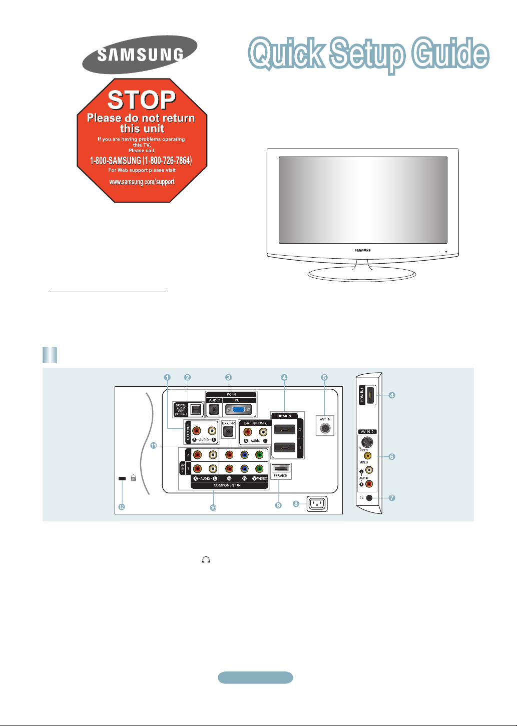
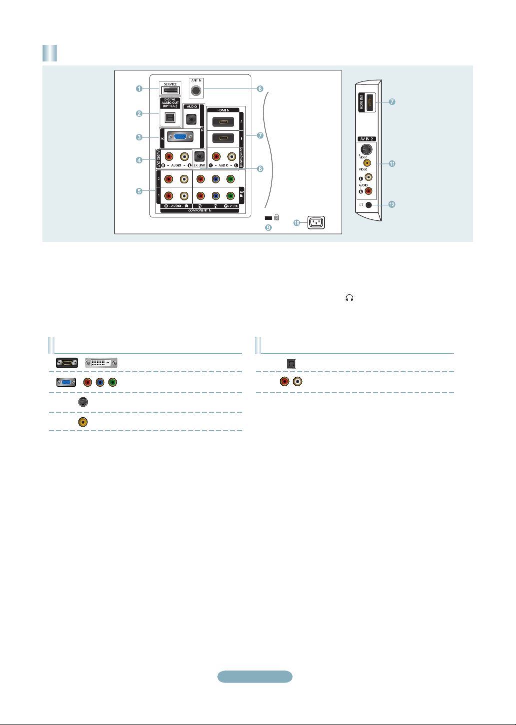
Rear Panel / Side Panel Jacks
1 AUDIO OUT
2 DIGITAL AUDIO OUT (OPTICAL)
3 PC IN [PC] / [AUDIO]
4 HDMI IN 1, 2, 3 / DVI IN (HDMI2)
[R-AUDIO-L]
5 ANT IN
6 AV IN 2
7 HEADPHONE
8 POWER INPUT
(LN26A450C1D, LN40A450C1D)
9 SERVICE
0 COMPONENT IN 1, 2 / AV IN 1
! EX-LINK
@ KENSINGTON LOCK
English-1
Page 2

Rear Panel / Side Panel Jacks
(LN32A450C1D, LN37A450C1D)
1 SERVICE
2 DIGITAL AUDIO OUT (OPTICAL)
3 PC IN [PC] / [AUDIO]
4 AUDIO OUT
5 COMPONENT IN 1, 2 / AV IN 1
6 ANT IN
7 HDMI IN 1, 2, 3 / DVI IN (HDMI1)
[R-AUDIO-L]
8 EX-LINK
Video Input Performance Comparison
/
/
HDMI/DVI
PC/COMPONENT
S-VIDEO
VIDEO
Best
Better
Good
Normal
9 KENSINGTON LOCK
0 POWER INPUT
! AV IN 2
@ HEADPHONE
Audio Output Performance Comparison
OPTICAL (Digital)
AUDIO (Analog)
Best
Normal
English-2
Page 3

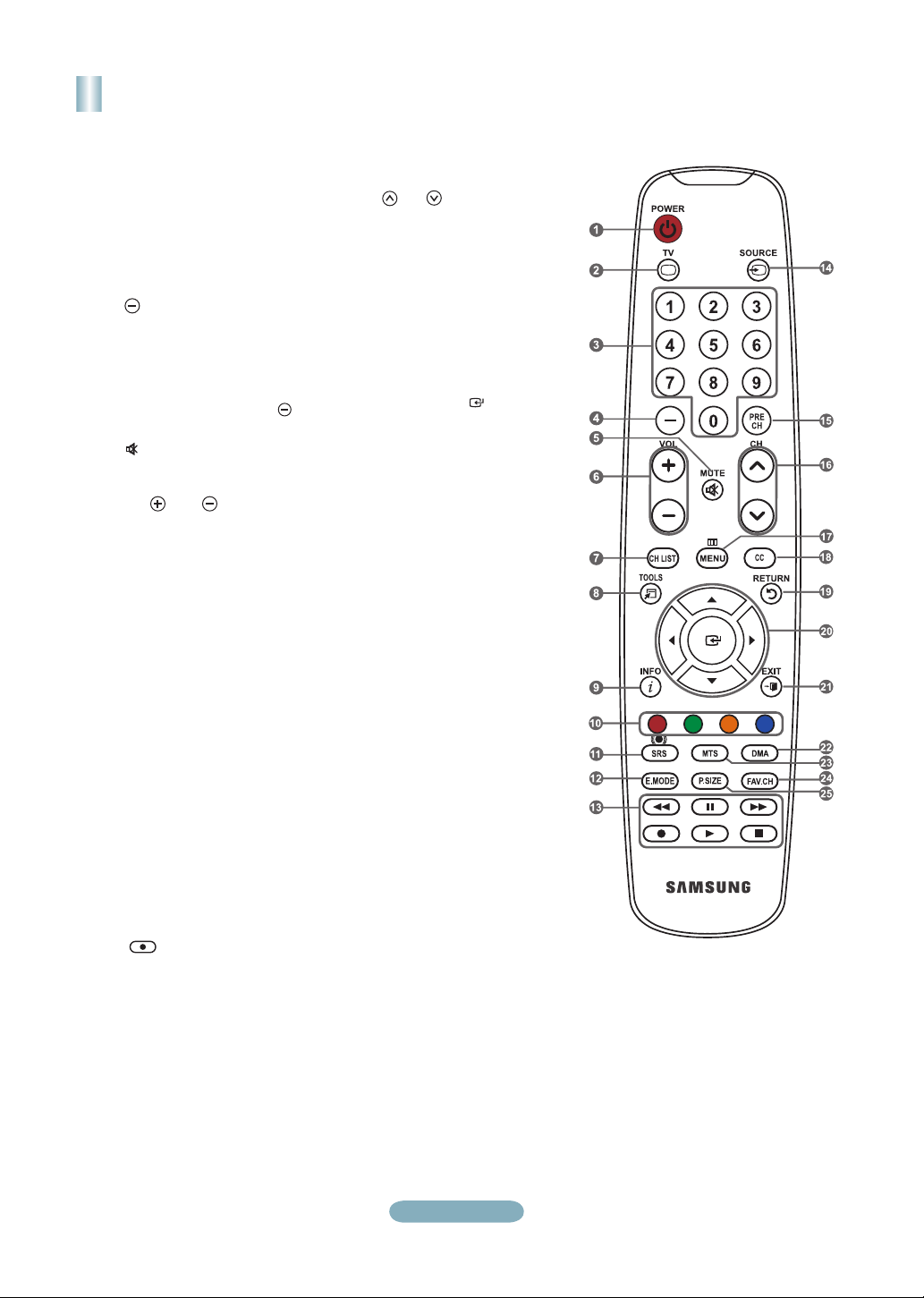
Remote Control
See “Remote Control” in the owner’s instructions for details.
1
POWER
Turns the TV on and off.
2
TV
Selects the TV mode directly.
3
NUMERIC BUTTONS
Press to change the channel.
4
Press to select additional
channels (digital and analog)
being broadcast by the same
station. For example, to select
channel “54-3”, press “54”, then
press “ ” and “3”.
5
(MUTE)
Press to temporarily cut off the
sound.
6
VOL- / VOL+
Press to increase or decrease
the volume.
7
CH LIST
Used to display Channel Lists
on the screen.
8
TOOLS
Use to quickly select frequently
used functions.
9
INFO
Press to display information on
the TV screen.
0
COLOR BUTTONS
Use these buttons in the
Channel list, etc.
!
SRS
Selects SRS TruSurround XT
mode.
@
E.MODE
Press to select the preset
display and sound modes for
sports, cinema and games.
#
Use these buttons in the DMA
and Anynet+ modes.
( : This remote can be
used to control recording on
Samsung recorders with the
Anynet+ feature)
$
SOURCE
Press to display and select the
available video sources.
%
PRE-CH
Tunes to the previous channel.
^
CH> / CH<
Press to change channels.
&
MENU
Displays the main on-screen
menu.
*
CC
Controls the caption decoder.
(
RETURN
Returns to the previous menu.
)
UP▲/DOWN▼/LEFT◄/
RIGHT►/ENTER
Use to select on-screen menu
items and change menu values.
a
EXIT
Press to exit the menu.
b
DMA (Digital Media Adapter)
Use this when connecting
a SAMSUNG DMA device
through an HDMI interface and
switching to DMA mode.
For more information on the
operating procedures, refer to
the user manual of the DMA.
This button is available when
"Anynet+(HDMI-CEC)" is "On".
c
MTS
Press to choose stereo, mono
or Separate Audio Program
(SAP broadcast).
d
FAV.CH
Press to switch to your favorite
channels.
e
P.SIZE
Picture size selection.
English-3
Page 4

Connections (LN26A450C1D, LN40A450C1D)
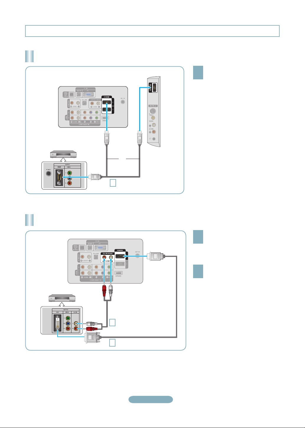
Connecting a DVD Player or Cable Box/Satellite receiver (Set-Top Box) via HDMI
TV Side Panel
TV Rear Panel
DVD Player or Cable Box/
Satellite receiver (Set-Top Box)
or
HDMI Cable (Not supplied)
1
Each DVD Player or Cable Box/Satellite receiver (Set-Top Box) has a different back panel configuration.
➣
Connect an HDMI Cable between
the HDMI IN (1, 2 or 3) jack on
1
the TV and the HDMI jack on the
DVD Player or Cable Box/Satellite
receiver (Set-Top Box).
What is HDMI?
•
HDMI(High-Definition Multimedia
Interface), is an interface that enables the
transmission of digital audio and video
signals using a single cable.
•
The difference between HDMI and DVI
is that the HDMI device is smaller in
size and has the HDCP (High Bandwidth
Digital Copy Protection) coding feature
installed.
Connecting a DVD Player or Cable Box/Satellite receiver (Set-Top Box) via DVI
TV Rear Panel
DVD Player or Cable Box/
Satellite receiver (Set-Top Box)
Audio Cable (Not supplied)
2
DVI to HDMI Cable (Not supplied)
1
Each DVD Player or Cable Box/Satellite receiver (Set-Top Box) has a different back panel configuration.
➣
When connecting a DVD Player or Cable Box/Satellite receiver (Set-Top Box), match the color of the connection terminal to the
➣
cable.
When using an HDMI/DVI cable connection, you must use the HDMI IN 2 jack.
➣
Connect a DVI to HDMI Cable or
DVI-HDMI Adapter between the
1
HDMI IN 2 jack on the TV and the DVI
jack on the DVD Player or Cable Box/
Satellite receiver (Set-Top Box).
Connect Audio Cables between the
DVI IN (HDMI 2) [R-AUDIO-L] jack on
2
the TV and the DVD Player or Cable
Box/Satellite receiver (Set-Top Box).
English-4
Page 5
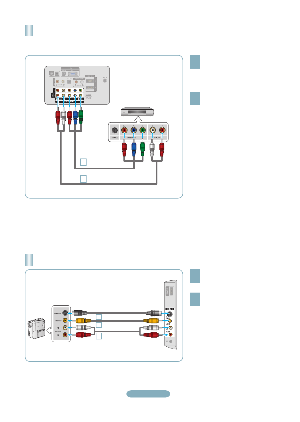
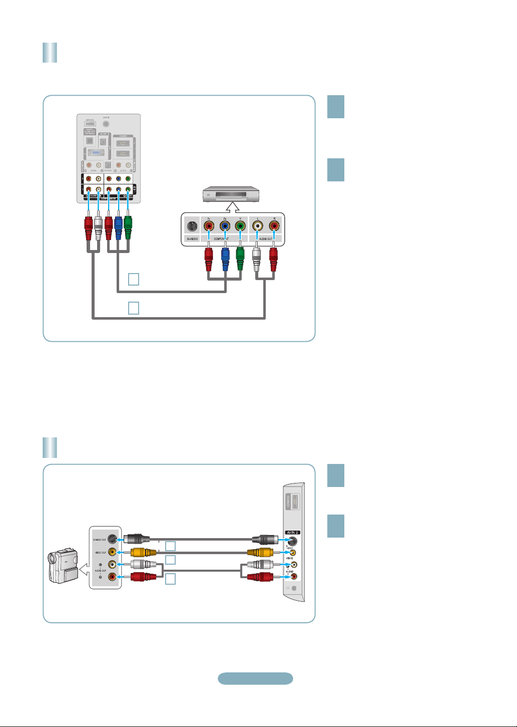
Connecting a DVD Player or Cable Box/Satellite receiver (Set-Top Box)
via Component cables
TV Rear Panel
1
2
DVD Player or Cable Box /
Satellite receiver (Set-Top Box)
Component Cable
(Not supplied)
Audio Cable (Not supplied)
Connect a Component Cable between
the COMPONENT IN (1 or 2)
1
[Y, PB, PR] jacks on the TV and the
COMPONENT [Y, PB, PR] jacks on
the DVD Player or Cable Box/Satellite
receiver (Set-Top Box).
Connect Audio Cables between the
COMPONENT IN(1 or 2) [R-AUDIO-L]
2
jacks on the TV and the AUDIO OUT
jacks on the DVD Player or Cable
Box/Satellite receiver (Set-Top Box).
Component video separates the video
➣
into Y (Luminance (brightness)), Pb
(Blue) and Pr (Red) for enhanced video
quality.
Be sure to match the component video
and audio connections.
For example, if connecting
a Component video cable to
COMPONENT IN 1, connect the audio
cable to COMPONENT IN 1 also.
Each DVD Player or Cable Box/
➣
Satellite receiver (Set-Top Box) has a
different back panel configuration.
When connecting a DVD Player or
➣
Cable Box/Satellite receiver (Set-Top
Box), match the color of the connection
terminal to the cable.
Connecting a Camcorder
Camcoder
S-Video cable (Not supplied)
or
1
Video cable (Not supplied)
1
Audio cable
2
(Not supplied)
English-5
TV Side Panel
Connect a Video Cable (or S-Video
Cable) between the AV IN 2 [VIDEO]
1
(or S-VIDEO) jack on the TV and the
VIDEO OUT jack on the camcorder.
Connect Audio Cables between the
AV IN 2 [R-AUDIO-L] jacks on the
2
TV and the AUDIO OUT jacks on the
camcorder.
Each Camcorder has a different back
➣
panel configuration.
When connecting a Camcorder, match
➣
the color of the connection terminal to
the cable.
Page 6
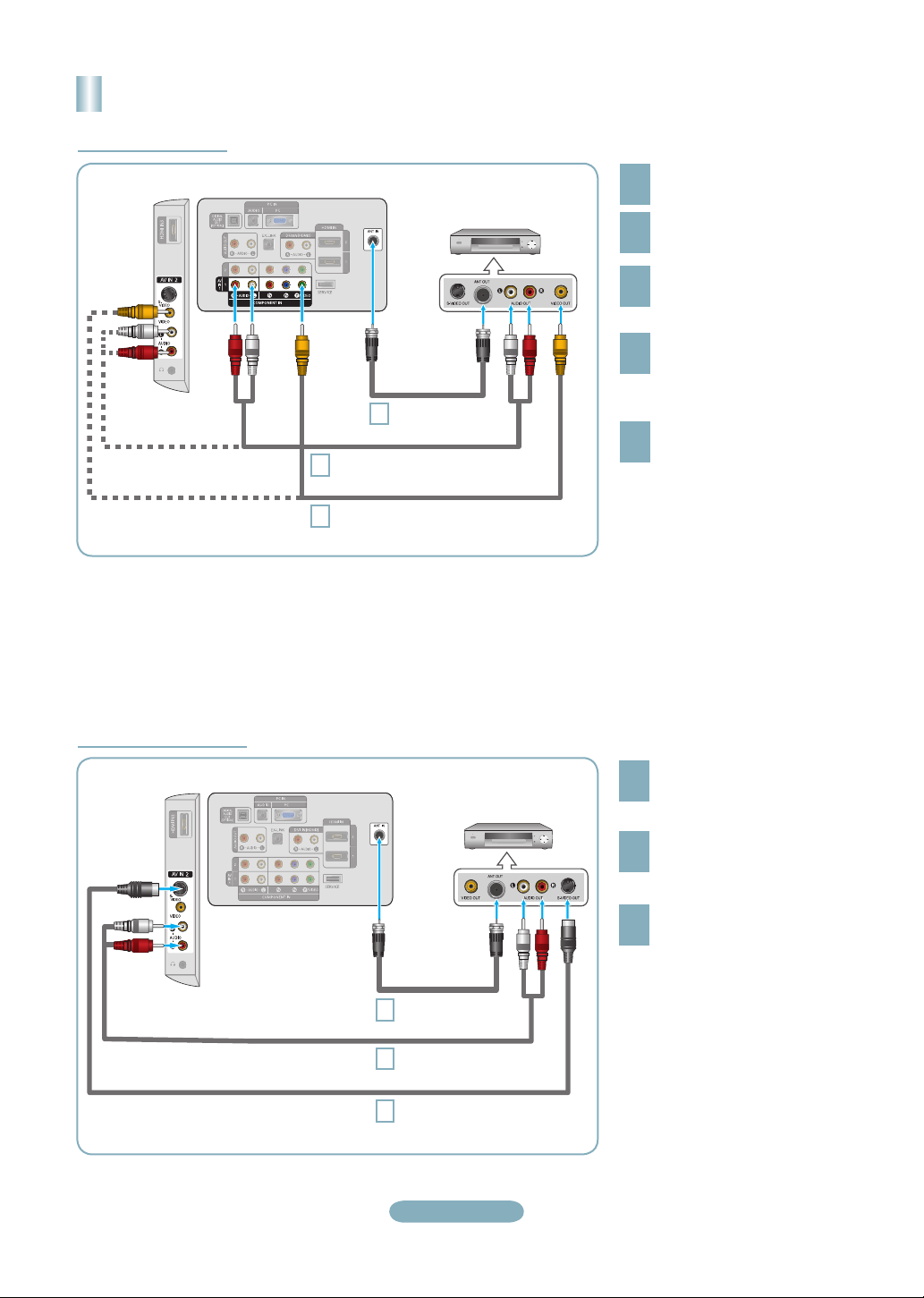
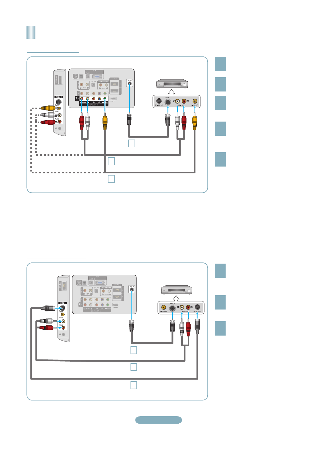
Connecting a VCR
Video Connection
TV Side Panel
Follow the instructions in “Viewing a VCR or Camcorder Tape” to view your VCR tape.
Each VCR has a different back panel configuration.
➣
When connecting a VCR, match the color of the connection terminal to the cable.
➣
When connecting to AV IN 1, the color of the AV IN 1 [Y/VIDEO] jack (Green) does not match the color of the video cable
➣
(Yellow).
TV Rear Panel
RF Cable
3
Audio Cable (Not supplied)
5
Video Cable (Not supplied)
4
VCR Rear Panel
(Not supplied)
Unplug the cable or antenna
from the back of the TV.
1
Connect the cable or antenna
to the ANT IN terminal on the
2
back of the VCR.
Connect an RF Cable between
the ANT OUT terminal on the
3
VCR and the ANT IN terminal
on the TV.
Connect a Video Cable
between the VIDEO OUT jack
4
on the VCR and the AV IN 1
[Y/VIDEO] or AV IN 2 [VIDEO]
jack on the TV.
Connect Audio Cables between
the AUDIO OUT jacks on the
5
VCR and the AV IN 1 (or AV IN 2)
[R-AUDIO-L] jacks on the TV.
If you have a “mono” (non-stereo)
➣
VCR, use a Y-connector (not
supplied) to hook up to the right
and left audio input jacks of the
TV. If your VCR is stereo, you
must connect two cables.
S-Video Connection
TV Side Panel
TV Rear Panel
VCR Rear Panel
RF Cable
1
2
3
(Not supplied)
Audio Cable (Not supplied)
S-Video Cable (Not supplied)
English-6
To begin, follow steps 1–3 in
the previous section to connect
1
the antenna or cable to your
VCR and your TV.
Connect Audio Cables between
the AUDIO OUT jacks on the
2
VCR and the AV IN 2
[R-AUDIO-L] jacks on the TV.
Connect an S-Video Cable
between the S-VIDEO OUT jack
3
on the VCR and the AV IN 2
[S-VIDEO] jack on the TV.
An S-Video cable may be included
with a VCR. (If not, check your local
electronics store.)
Each VCR has a different back
➣
panel configuration.
When connecting a VCR, match
➣
the color of the connection
terminal to the cable.
Page 7
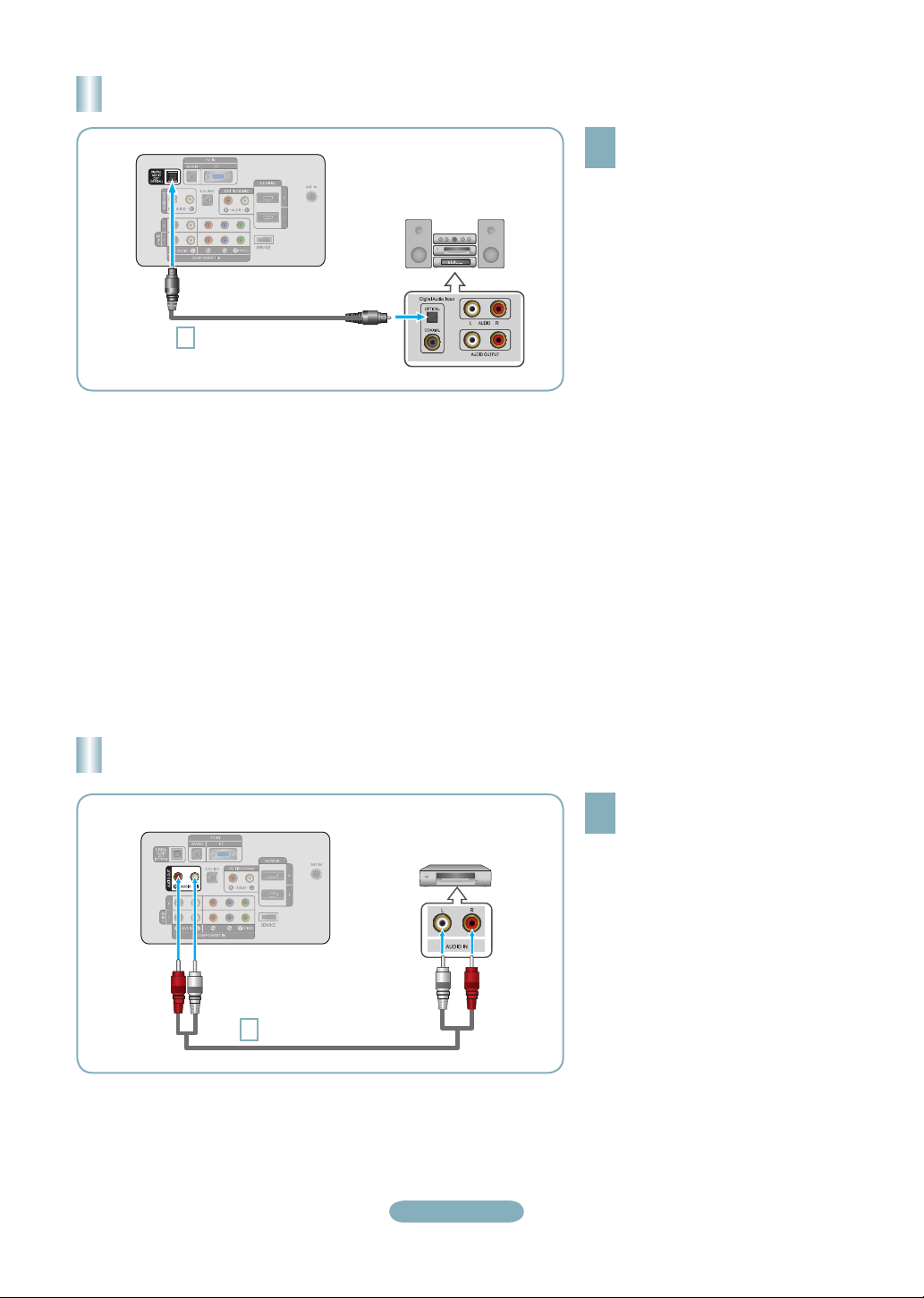
Connecting a Digital Audio System
TV Rear Panel
Optical Cable (Not supplied)
1
Digital Audio System
Connect an Optical Cable between
the “DIGITAL AUDIO OUT
1
(OPTICAL)” jacks on the TV and
the Digital Audio Input jacks on the
Digital Audio System.
When a Digital Audio System is
connected to the “DIGITAL AUDIO
OUT (OPTICAL)” jack: Decrease
the volume of the TV and adjust
the volume level with the system’s
volume control.
5.1CH audio is possible when the TV
➣
is connected to an external device
supporting 5.1CH.
Each Digital Audio System has a
➣
different back panel configuration.
When the receiver (home theater) is
➣
set to On, you can hear sound output
from the TV’s Optical jack. When the TV
is displaying a DTV(air) signal, the TV
will send out 5.1 channel sound to the
Home theater receiver. When the source
is a digital component such as a DVD
and is connected to the TV via HDMI,
only 2 channel sound will be heard from
the Home Theater receiver. If you want
to hear 5.1 channel audio, connect the
DIGITAL AUDIO OUT (OPTICAL) jack
on the DVD player or Cable/Satellite
Box directly to an Amplifier or Home
Theater, not the TV.
Connecting an Amplifier/DVD Home Theater
Connect Audio Cables between the
AUDIO OUT [R-AUDIO-L] jacks on
TV Rear Panel
Audio Cable (Not supplied)
1
Amplifier/DVD Home Theater
English-7
1
the TV and AUDIO IN [R-AUDIO-L]
jacks on the Amplifier/DVD Home
Theater.
When an audio amplifier is
connected to the "AUDIO OUT
[R-AUDIO-L]" jacks: Decrease the
volume of the TV and adjust the
volume level with the Amplifier’s
volume control.
Each Amplifier/DVD Home Theater has
➣
a different back panel configuration.
When connecting an Amplifier/DVD
➣
Home Theater, match the color of the
connection terminal to the cable.
Page 8
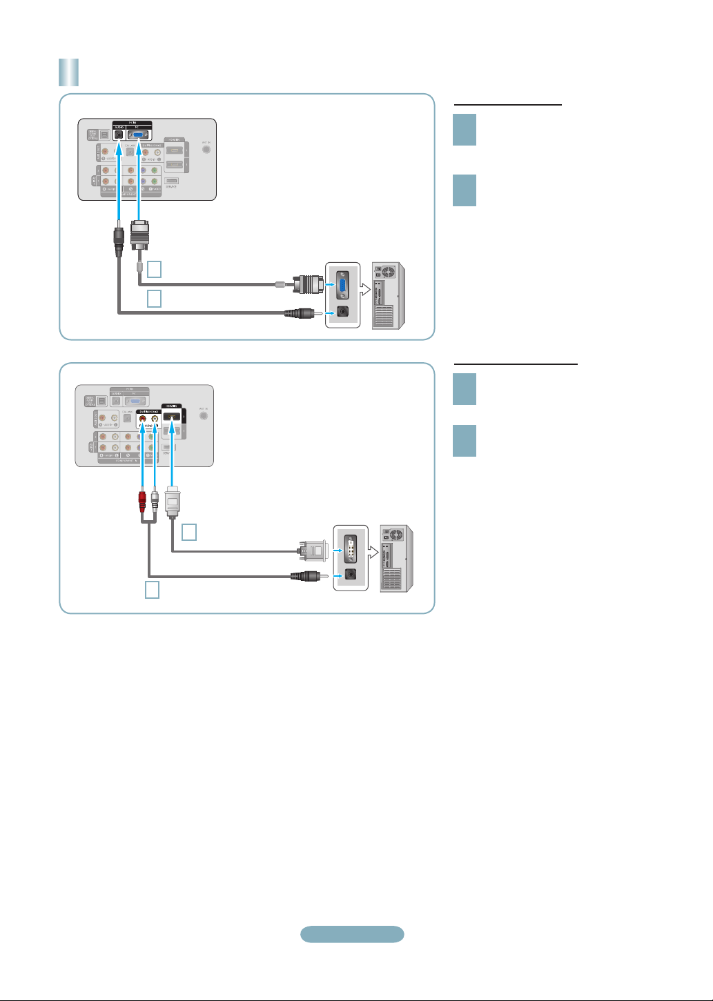
Connecting a PC
TV Rear Panel
D-Sub Cable (Not supplied)
1
PC Audio Cable (Not supplied)
2
TV Rear Panel
PC
Using the D-Sub Cable
Connect a D-Sub Cable between
PC IN [PC] connector on the TV
1
and the PC output connector on
your computer.
Connect a PC Audio Cable
between the PC IN [AUDIO] jack
2
on the TV and the Audio Out jack of
the sound card on your computer.
Using the HDMI/DVI Cable
Connect an HDMI/DVI cable between
the HDMI IN 2 jack on the TV and
1
the PC output jack on your computer.
Connect a 3.5 mm Stereo miniplug/2RCA Cable between the DVI
2
IN(HDMI2) [R-AUDIO-L] jack on the
TV and the Audio Out jack of the
sound card on your computer.
HDMI/DVI Cable (Not supplied)
1
3.5 mm Stereo mini-plug/2RCA Cable (Not supplied)
2
PC
➣
Each PC has a different back panel
configuration.
When connecting a PC, match the
➣
color of the connection terminal to the
cable.
When using an HDMI/DVI cable
➣
connection, you must use the HDMI
IN 2 jack.
English-8
Page 9
Connections (LN32A450C1D, LN37A450C1D)
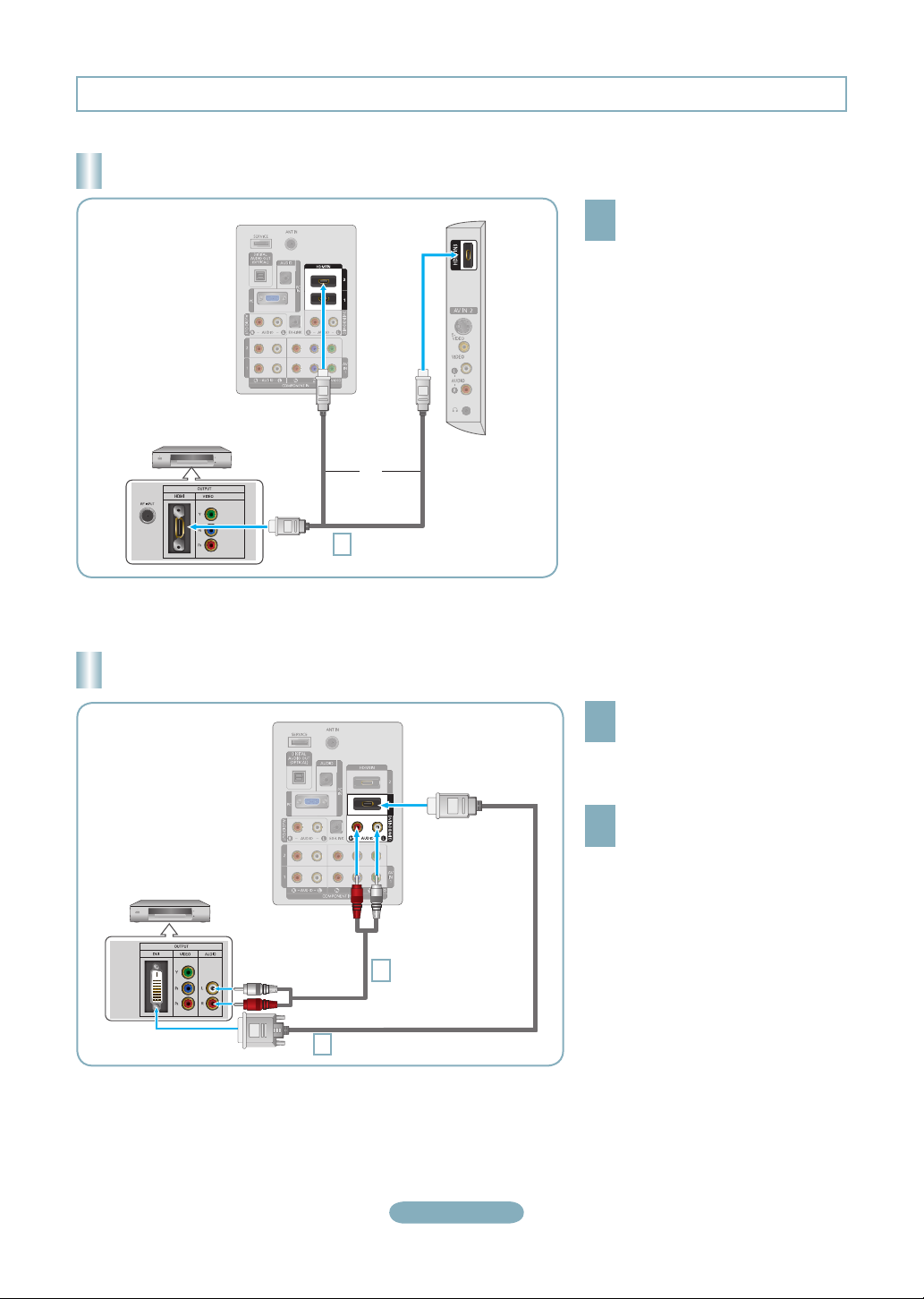
Connecting a DVD Player or Cable Box/Satellite receiver (Set-Top Box) via HDMI
TV Rear Panel
DVD Player or Cable Box/
Satellite receiver (Set-Top Box)
or
HDMI Cable (Not supplied)
1
Each DVD Player or Cable Box/Satellite receiver (Set-Top Box) has a different back panel configuration.
➣
TV Side Panel
Connect an HDMI Cable between
the HDMI IN (1, 2 or 3) jack on
1
the TV and the HDMI jack on the
DVD Player or Cable Box/Satellite
receiver (Set-Top Box).
What is HDMI?
•
HDMI(High-Definition Multimedia
Interface), is an interface that enables the
transmission of digital audio and video
signals using a single cable.
•
The difference between HDMI and DVI
is that the HDMI device is smaller in
size and has the HDCP (High Bandwidth
Digital Copy Protection) coding feature
installed.
Connecting a DVD Player or Cable Box/Satellite receiver (Set-Top Box) via DVI
TV Rear Panel
DVD Player or Cable Box/
Satellite receiver (Set-Top Box)
Audio Cable (Not supplied)
2
DVI to HDMI Cable (Not supplied)
1
Each DVD Player or Cable Box/Satellite receiver (Set-Top Box) has a different back panel configuration.
➣
When connecting a DVD Player or Cable Box/Satellite receiver (Set-Top Box), match the color of the connection terminal to the
➣
cable.
When using an HDMI/DVI cable connection, you must use the HDMI IN 1 jack.
➣
Connect a DVI to HDMI Cable or
DVI-HDMI Adapter between the HDMI
1
IN 1 jack on the TV and the DVI jack
on the DVD Player or Cable Box/
Satellite receiver (Set-Top Box).
Connect Audio Cables between the
DVI IN (HDMI 1) [R-AUDIO-L] jack on
2
the TV and the DVD Player or Cable
Box/Satellite receiver (Set-Top Box).
English-9
Page 10

Connecting a DVD Player or Cable Box/Satellite receiver (Set-Top Box)
via Component cables
TV Rear Panel
Component Cable
1
(Not supplied)
Audio Cable (Not supplied)
2
DVD Player or Cable Box /
Satellite receiver (Set-Top Box)
Connect a Component Cable
between the COMPONENT IN (1 or
1
2) [Y, PB, PR] jacks on the TV and the
COMPONENT [Y, PB, PR] jacks on
the DVD Player or Cable Box/Satellite
receiver (Set-Top Box).
Connect Audio Cables between the
COMPONENT IN(1 or 2) [R-AUDIO-L]
2
jacks on the TV and the AUDIO OUT
jacks on the DVD Player or Cable Box/
Satellite receiver (Set-Top Box).
Component video separates the video
➣
into Y (Luminance (brightness)), Pb
(Blue) and Pr (Red) for enhanced
video quality. Be sure to match
the component video and audio
connections.
For example, if connecting
a Component video cable to
COMPONENT IN 1, connect the audio
cable to COMPONENT IN 1 also.
Each DVD Player or Cable Box/
➣
Satellite receiver (Set-Top Box) has a
different back panel configuration.
When connecting a DVD Player or
➣
Cable Box/Satellite receiver (Set-Top
Box), match the color of the connection
terminal to the cable.
Connecting a Camcorder
Camcoder
S-Video cable (Not supplied)
or
1
Video cable (Not supplied)
1
Audio cable
2
(Not supplied)
English-10
TV Side Panel
Connect a Video Cable (or S-Video
Cable) between the AV IN2 [VIDEO]
1
(or S-VIDEO) jack on the TV and the
VIDEO OUT jack on the camcorder.
Connect Audio Cables between the
AV IN2 [R-AUDIO-L] jacks on the TV
2
and the AUDIO OUT jacks on the
camcorder.
Each Camcorder has a different back
➣
panel configuration.
When connecting a Camcorder, match
➣
the color of the connection terminal to
the cable.
Page 11
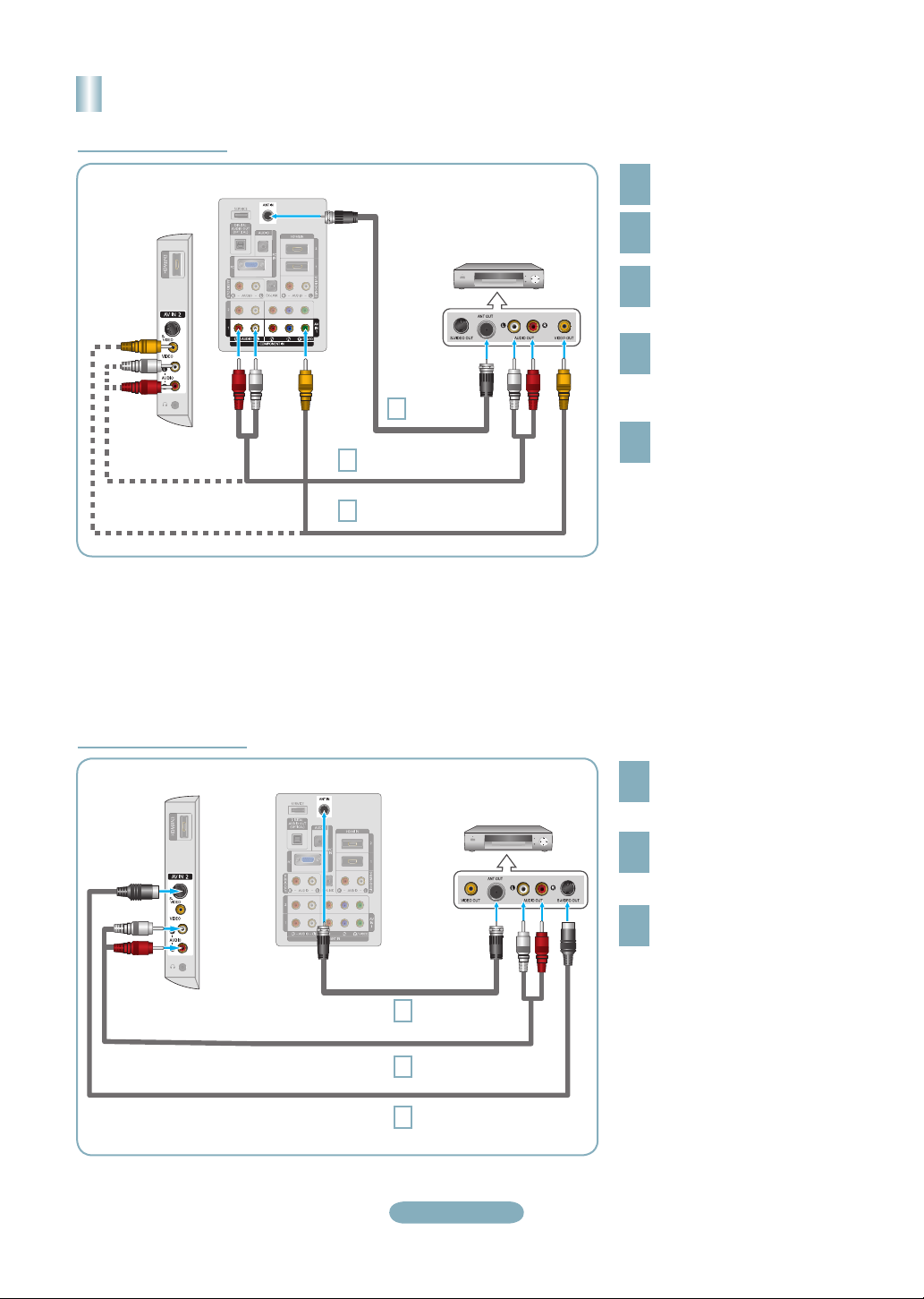
Connecting a VCR
Video Connection
TV Rear Panel
TV Side Panel
VCR Rear Panel
RF Cable
3
(Not supplied)
Audio Cable
5
(Not supplied)
Video Cable
4
(Not supplied)
Follow the instructions in “Viewing a VCR or Camcorder Tape” to view your VCR tape.
Each VCR has a different back panel configuration.
➣
When connecting a VCR, match the color of the connection terminal to the cable.
➣
When connecting to AV IN 1, the color of the AV IN 1 [Y/VIDEO] jack (Green) does not match the color of the video cable
➣
(Yellow).
Unplug the cable or antenna
from the back of the TV.
1
Connect the cable or antenna
to the ANT IN terminal on the
2
back of the VCR.
Connect an RF Cable between
the ANT OUT terminal on the
3
VCR and the ANT IN terminal
on the TV.
Connect a Video Cable
between the VIDEO OUT jack
4
on the VCR and the AV IN 1
[Y/VIDEO] or AV IN 2 [VIDEO]
jack on the TV.
Connect Audio Cables between
the AUDIO OUT jacks on the
5
VCR and the AV IN 1 (or AV IN 2)
[R-AUDIO-L] jacks on the TV.
If you have a “mono” (non-stereo)
➣
VCR, use a Y-connector (not
supplied) to hook up to the right
and left audio input jacks of the
TV. If your VCR is stereo, you
must connect two cables.
S-Video Connection
TV Side Panel
TV Rear Panel
RF Cable
1
(Not supplied)
Audio Cable
2
(Not supplied)
S-Video Cable
3
(Not supplied)
English-11
VCR Rear Panel
To begin, follow steps 1–3 in
the previous section to connect
1
the antenna or cable to your
VCR and your TV.
Connect Audio Cables between
the AUDIO OUT jacks on the
2
VCR and the AV IN 2
[R-AUDIO-L] jacks on the TV.
Connect an S-Video Cable
between the S-VIDEO OUT jack
3
on the VCR and the AV IN 2
[S-VIDEO] jack on the TV.
An S-Video cable may be included
with a VCR. (If not, check your local
electronics store.)
Each VCR has a different back
➣
panel configuration.
When connecting a VCR, match
➣
the color of the connection
terminal to the cable.
Page 12

Connecting a Digital Audio System
TV Rear Panel
Optical Cable (Not supplied)
1
Digital Audio System
Connect an Optical Cable between
the “DIGITAL AUDIO OUT
1
(OPTICAL)” jacks on the TV and
the Digital Audio Input jacks on the
Digital Audio System.
When a Digital Audio System is
connected to the “DIGITAL AUDIO
OUT (OPTICAL)” jack: Decrease
the volume of the TV and adjust
the volume level with the system’s
volume control.
5.1CH audio is possible when the TV
➣
is connected to an external device
supporting 5.1CH.
Each Digital Audio System has a
➣
different back panel configuration.
When the receiver (home theater) is
➣
set to On, you can hear sound output
from the TV’s Optical jack. When the TV
is displaying a DTV(air) signal, the TV
will send out 5.1 channel sound to the
Home theater receiver. When the source
is a digital component such as a DVD
and is connected to the TV via HDMI,
only 2 channel sound will be heard from
the Home Theater receiver. If you want
to hear 5.1 channel audio, connect the
DIGITAL AUDIO OUT (OPTICAL) jack
on the DVD player or Cable/Satellite
Box directly to an Amplifier or Home
Theater, not the TV.
Connecting an Amplifier/DVD Home Theater
TV Rear Panel
Audio Cable (Not supplied)
1
Amplifier/DVD Home Theater
English-12
Connect Audio Cables between the
AUDIO OUT [R-AUDIO-L] jacks on
1
the TV and AUDIO IN [R-AUDIO-L]
jacks on the Amplifier/DVD Home
Theater.
When an audio amplifier is
connected to the "AUDIO OUT
[R-AUDIO-L]" jacks: Decrease the
volume of the TV and adjust the
volume level with the Amplifier’s
volume control.
Each Amplifier/DVD Home Theater has
➣
a different back panel configuration.
When connecting an Amplifier/DVD
➣
Home Theater, match the color of the
connection terminal to the cable.
Page 13

Connecting a PC
TV Rear Panel
D-Sub Cable (Not supplied)
1
PC Audio Cable (Not supplied)
2
TV Rear Panel
PC
Using the D-Sub Cable
Connect a D-Sub Cable between
PC IN [PC] connector on the TV and
1
the PC output connector on your
computer.
Connect a PC Audio Cable between
the PC IN [AUDIO] jack on the TV
2
and the Audio Out jack of the sound
card on your computer.
Using the HDMI/DVI Cable
Connect a HDMI/DVI cable between
the HDMI IN 1 jack on the TV and
1
the PC output jack on your computer.
Connect a 3.5 mm Stereo miniplug/2RCA Cable between the DVI
2
IN(HDMI1) [R-AUDIO-L] jack on the
TV and the Audio Out jack of the
sound card on your computer.
HDMI/DVI Cable (Not supplied)
1
3.5 mm Stereo mini-plug/2RCA Cable (Not supplied)
2
PC
Each PC has a different back panel
➣
configuration.
When connecting a PC, match the
➣
color of the connection terminal to the
cable.
When using an HDMI/DVI cable
➣
connection, you must use the HDMI
IN 1 jack.
English-13
Page 14
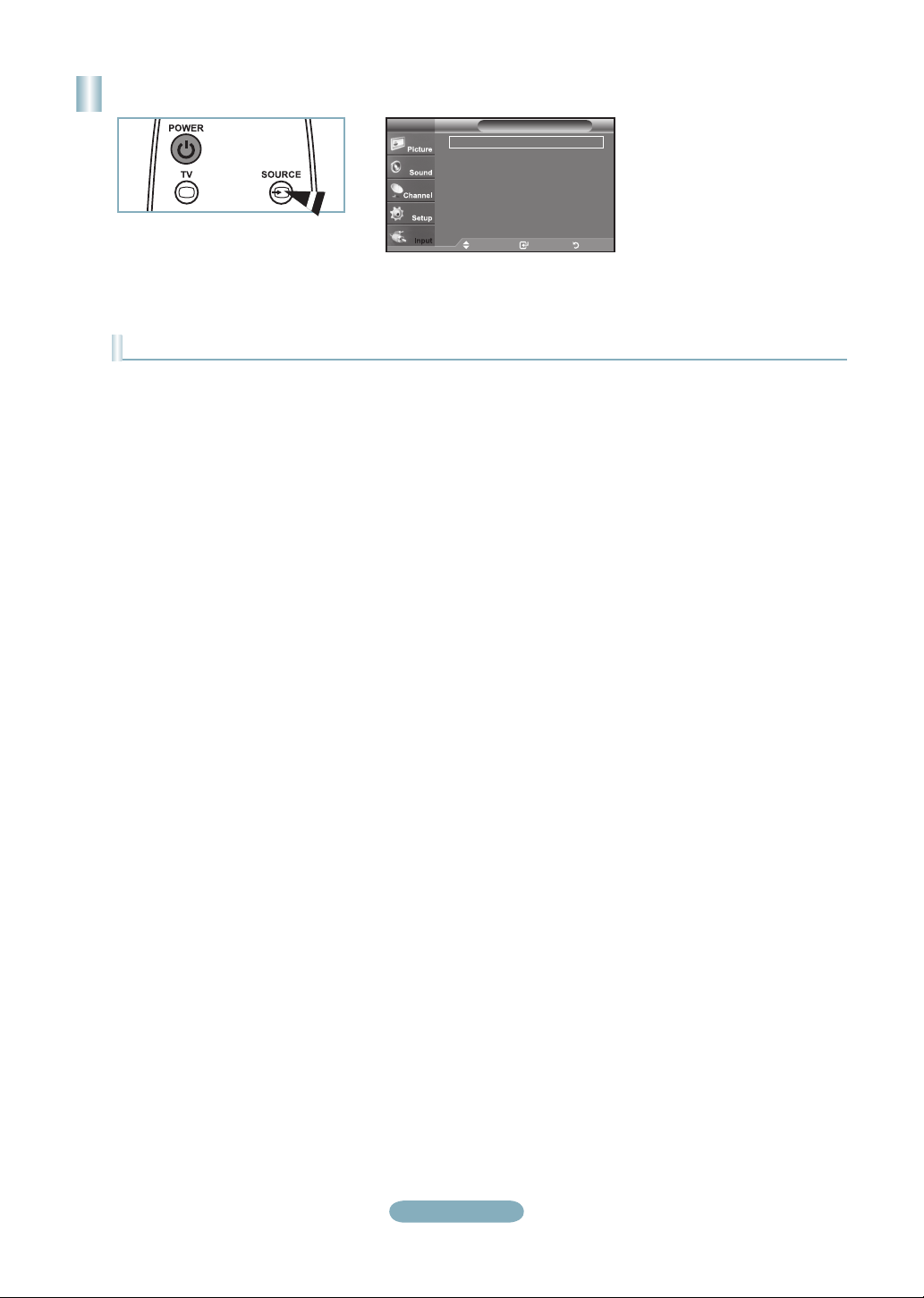
Turning the TV On and Off
Press the POWER button on the remote control.
You can also use the POWER button on the TV.
Viewing the Menus
With the power on, press the MENU button.
The main menu appears on the screen.
1
The menu’s left side has icons:Picture, Sound,
Channel, Setup, Input.
Press the ▲ or ▼ button to select one of the icons.
Then press the ENTER
2
icon’s sub-menu. Press the EXIT button to exit.
The on-screen menus disappear from the
➣
button to access the
screen after about one minute.
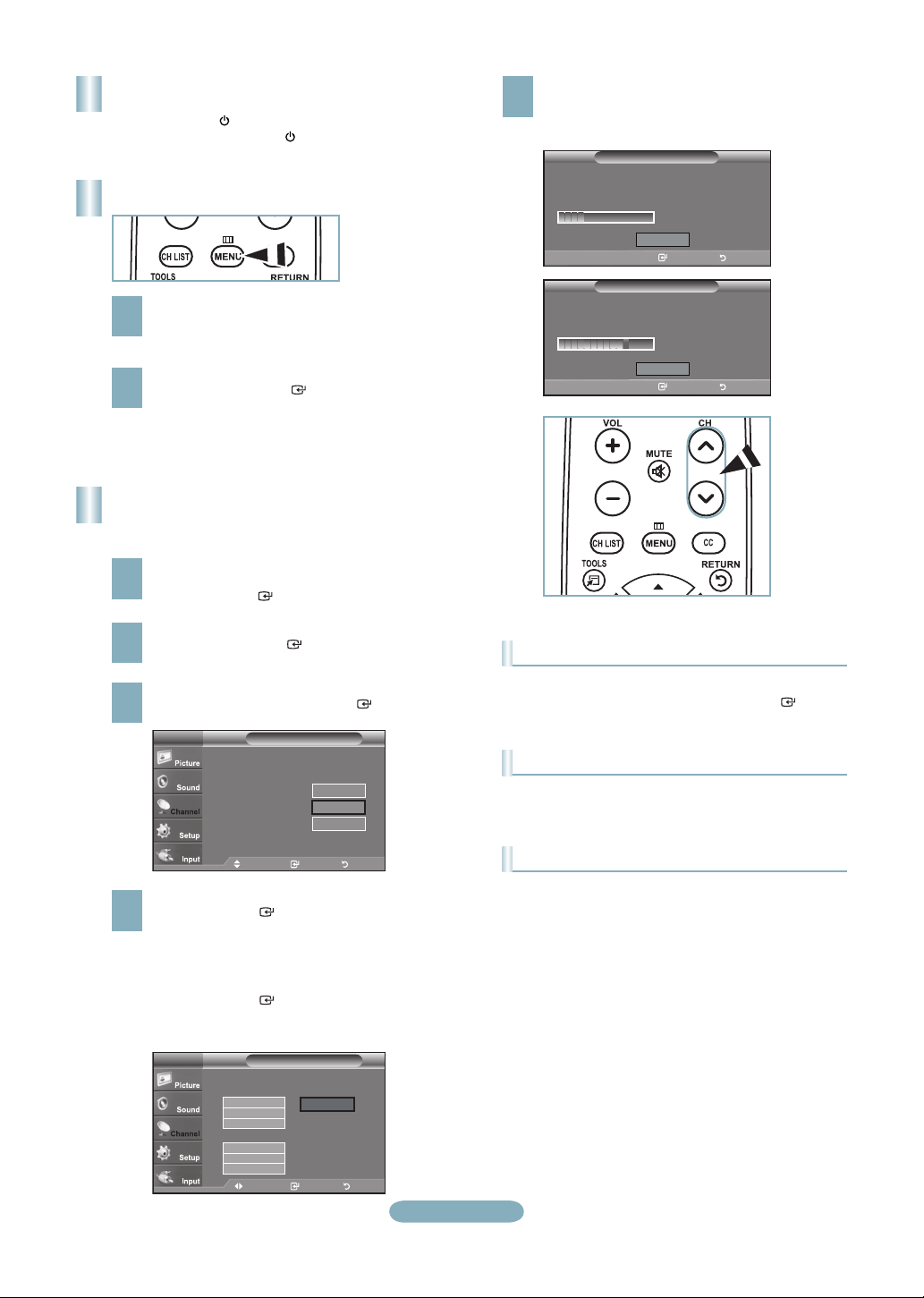
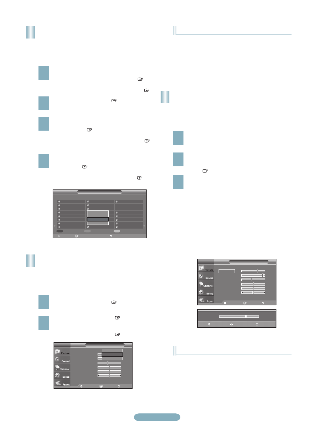
Storing Channels in Memory
(Automatic Method)
Press the MENU button to display the menu.
Press the ▲ or ▼ button to select “Channel”, then
1
press the ENTER button.
The TV begins memorizing all available stations.
After all the available channels are stored, it start to
5
remove scrambled channels.
Press the EXIT button to exit.
Auto Program
Plug & Play
Auto Program in Progress.
DTV Cable : -- Cable : 11
Enter Return
Removing scrambled channel.
Enter Return
Auto Program
Stop
Auto Program
Plug & Play
Auto Program
Stop
Cable 24
11 %
DTV Cable 55
80 %
Press the ▲ or ▼ button to select “Auto Program”,
then press the ENTER button.
2
Press the ▲ or ▼ button to select the antenna
connection, then press the ENTER button.
3
TV
Selects the antenna to execute the Auto
Program function.
Auto Program
Air
Cable
Auto
Move Enter Return
Move Enter Return
Start
Start
Start
When selecting the Cable TV system:
Press the ENTER button to start the auto
4
program.
Press the ◄ or ► button, then press the ▲ or ▼ to
select the correct analog signal cable system source
among “STD”, “HRC”, and “IRC”.
Press the ENTER button.
If you have Digital cable TV, select the cable system
signal source for both Analog and Digital.
TV
Selects a cable signal type for your location.
Auto Program
Analog
STD
HRC
IRC
Digital
STD
HRC
IRC
Move Enter Return
Move Enter Return
Start
English-14
To Stop the Auto Program Function
Press the MENU button while the Auto Program function is
being executed. You can also press the ENTER button
to stop the setup.
Checking to see if Channels were Stored in Memory
Press the CH button. Only the channels stored in memory
will be selected (in order).
Selecting the antennas
• Air: “Air” antenna signal.
• Cable: “Cable” antenna signal.
• Auto: “Air” and “Cable” antenna signals.
Page 15

Setting the Channel List
Picture Mode
Using this menu, you can Add/Delete or set Favorite
channels and use the program guide for digital broadcasts.
To use the Channel List function, first run “Auto Program”.
Press the MENU button. Press the ▲ or ▼ button to
select “Channel”, then press the ENTER button.
1
Press the ▲ or ▼ button to select “Channel List”,
then press the ENTER button.
Press the ENTER button to select “All”.
2
Press the ◄, ►, ▲ or ▼ button to select a channel
to delete, then press the ENTER button.
3
Press the ▲ or ▼ button to select “Delete”, then
press the ENTER button to delete the channel.
Press the ◄, ►, ▲ or ▼ button to select a channel
to add, then press the ENTER button.
4
Press the ▲ or ▼ button to select “Add”, then press
the ENTER button to add the channel.
Air 5 1 / 2
DTV Air 2-1
Air3
Air4
Air 5
Air 6
Air 7
DTV Air 7-1
Air 8
List Mode Delete AllAdd All
Move Enter Return
Channel List / All
Air 9
Air 10
DTV Air 10-1
DTV Air 10-2
Watch
Add
DTV Air 10-3
Delete
DTV Air 10-1
Favorite
DTV Air 10-2
DTV Air 10-3
DTV Air 10-1
DTV Air 10-2
DTV Air 10-3
Air 12
DTV Air 13-1
DTV Air 13-2
DTV Air 13-3
DTV Air 13-4
• Dynamic: Selects the picture for high-definition in a bright
room.
• Standard: Selects the picture for the optimum display in a
normal environment.
• Movie: Selects the picture for viewing movies in a dark
room.
Customizing the Picture Settings
Your television has several setting options that allow you to
control the picture quality.
To select the desired picture mode, follow the
“Changing the Picture Standard” instructions
1
numbers 1 and 2.
Press the ▲ or ▼ button to select “Backlight”,
“Contrast”, “Brightness”, “Sharpness”, “Color” or
2
“Tint”, then press the ENTER button.
Press the ◄ or ► button to decrease or increase
the value of a particular item. Press the EXIT button
3
to exit.
➣
When you make changes to “Backlight”,
“Contrast”, “Brightness”, “Sharpness”, “Color”
or “Tint”, the OSD will be adjusted accordingly.
In PC mode, you can only make changes to
➣
“Backlight”, “Contrast” and “Brightness”.
➣
Settings can be adjusted and stored for each
external device you have connected to an input
of the TV.
Changing the Picture Standard
You can activate either Dynamic, Standard, Movie by
making a selection from the menu.
Press the MENU button to display the menu.
Press the ENTER button, to select “Picture”.
1
Press the ENTER button to select “Mode”.
Press the ▲ or ▼ button to select “Dynamic”,
2
“Standard” or “Movie”.
Press the ENTER button.
Mode : Dynamic
Backlight 7
Contrast 95
Brightness 45
Sharpness 50
Color 50
Tint G 50 R 50
▼More
PictureTV
Dynamic
Standard
Movie
Move Enter Return
English-15
Mode : Standard ►
Backlight 7
Contrast 95
Brightness 45
Sharpness 50
Color 50
Tint G 50 R 50
▼More
▲
Backlight
▼
Move Adjust Return
PictureTV
Move Enter Return
7
Picture Adjustment
• Backlight: Adjusts the brightness of LCD back light.
• Contrast: Adjusts the contrast level of the picture.
• Brightness: Adjusts the brightness level of the picture.
• Sharpness: Adjusts the edge definition of the picture.
• Color: Adjusts color saturation of the picture.
• Tint: Adjusts the color tint of the picture.
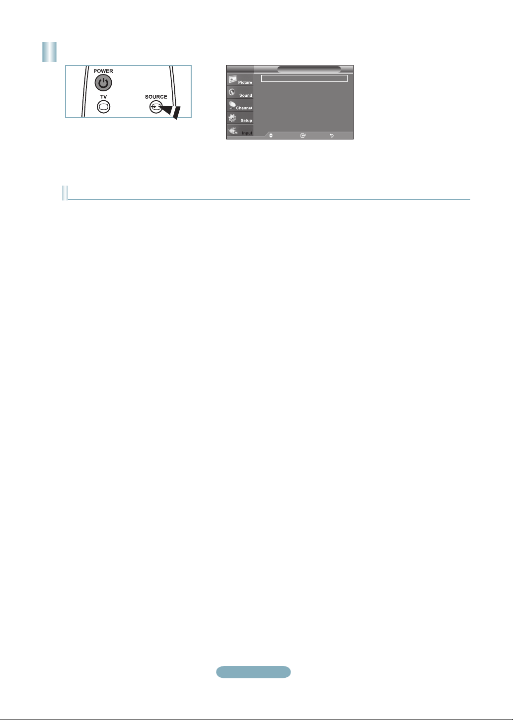
Page 16
To Select the Source
TV
AV1 : ---AV2 : ---S-Video : ---Component1 : ---Component2 : ---PC : ----
▼ more
Source ListTV
Move Enter Return
Press the SOURCE button on the Remote Control
You can select the TV mode or an input source connected to the TV set. Use this button to choose an input source that you
would like to watch.
Available signal sources: TV, AV1, AV2, S-Video, Component1, Component2, PC, HDMI1, HDMI2/DVI, HDMI3.
➣
You can choose only those external devices that are connected to the TV.
➣
English-16
Page 17

Troubleshooting
If the TV seems to have a problem, first try this list of possible problems and solutions.
If none of these troubleshooting tips apply, call Samsung customer service at 1-800-SAMSUNG.
Problem Possible Solution
Poor picture Try another channel. / Adjust the antenna. / Check all wire connections.
Poor sound quality. Try another channel. / Adjust the antenna.
No picture or sound. Try another channel. / Press the SOURCE button. /
No sound or sound is too low at maximum
volume.
Picture rolls vertically. Check all wire connections.
The TV operates erratically. Unplug the TV for 30 seconds, then try operating it again.
The TV won’t turn on. Make sure the wall outlet is working.
Remote control malfunctions Replace the remote control batteries.
“Check signal cable” message. Ensure that the signal cable is rmly connected to the PC source.
“Not Supported Mode” message. Check the maximum resolution and connected device’s Video frequency.
Digital broadcasting screen problem. Please check the digital signal strength and input antenna.
The image is too light or too dark. Adjust the Brightness and Contrast. / Adjust the Fine tuning.
Black bars on the screen. Make sure the broadcast you’re receiving is High Denition (HD).
Picture has a Red/Green or Pink tint. Make sure the Component cables are connected to the correct jacks.
Closed Captioning not working. If you are using a Cable/Satellite box, you must set Closed Captioning on the box,
Snowy picture. Your cable box may need a rmware upgrade. Please contact your Cable
Ghosting on picture This is sometimes caused by compatibility issues with your cable box.
Horizontal bars appear to icker, jitter or
shimmer on the image.
Vertical bars appear to icker, jitter or
shimmer on the image.
Screen is black and power indicator light
blinks steadily.
Image is not centered on the screen. Adjust the horizontal and vertical position.
The picture appears distorted in the
corner of the screen.
The “Resets all settings to the default
values” message appears
Make sure the TV is plugged in. / Check the antenna connections.
First, check the volume of units connected to your TV (digital broadcasting
receiver, DVD, cable broadcasting receiver, VCR, etc.). Then, adjust the TV
volume accordingly.
Clean the upper edge of the remote control (transmission window).
Check the battery terminals.
Compare these values with the data in the Display Modes.
HD channels sometimes broadcast Standard Denition (SD) programming, which
can cause black bars.
Set your cable/satellite box to stretch or widescreen mode to eliminate the bars.
not your TV.
company.
Try connecting Component cables instead.
Adjust the Coarse tuning and then adjust the Fine tuning.
Adjust the Coarse tuning and then adjust the Fine tuning.
On your computer check: Power, Signal Cable.
The TV is using its power management system.
Move the computer's mouse or press any key on the keyboard.
The screen position must be adjusted on the output source (i.e. STB) with a
digital signal.
If "Just Scan" is selected with some external devices, the picture may appear
distorted in the corner of the screen. This symptom is caused by the external
devices, not TV.
This appears when you press and hold the EXIT button for a while. The product
settings are reset to the factory defaults.
English-17
Page 18

Guide d'installation rapide
LN26A450C1D/LN32A450C1D/
LN37A450C1D/LN40A450C1D
1-800-SAMSUNG (7267864)
Samsung Electronics America, Inc.
105 Challenger Road Ridgefield Park, NJ 07660-0511
Samsung Electronics Canada Inc., Customer Service
55 Standish Court Mississauga, Ontario L5R 4B2
Centre d’appel – heures de service (du lundi au dimanche, de 9 h à 12 h (HNE)
Pour enregistrer ce produit, veuillez SVP aller à :
www.samsung.com/global/register.
Panneau arrière / Prises du panneau latéral (LN26A450C1D, LN40A450C1D)
1 AUDIO OUT
2 DIGITAL AUDIO OUT (OPTICAL)
3 PC IN [PC] / [AUDIO]
4 HDMI IN 1, 2, 3 / DVI IN (HDMI2)
[R-AUDIO-L]
5 ANT IN
6 AV IN 2/S-VIDEO
7 AURICULAR
8 ENTRADA DE ALIMENTACIÓN
9 SERVICE
0 COMPONENT IN 1, 2 / AV IN 1
! EX-LINK
@ BLOQUEO KENSINGTON
Français-1
Page 19
Panneau arrière / Prises du panneau latéral (LN32A450C1D, LN37A450C1D)
1 SERVICE
2 DIGITAL AUDIO OUT (OPTICAL)
3 PC IN [PC] / [AUDIO]
4 AUDIO OUT
5 COMPONENT IN 1, 2 / AV IN 1
6 ANT IN
7 HDMI IN 1, 2, 3 / DVI IN (HDMI1)
[R-AUDIO-L]
8 EX-LINK
Entrée vidéo – tableau comparatif des performances
/
/
HDMI/DVI
PC/COMPONENT
S-VIDÉO
VIDÉO
La meilleure
Excellente
Bonne
Normale
9 BLOQUEO KENSINGTON
0 ENTRADA DE ALIMENTACIÓN
! AV IN 2/S-VIDEO
@ AURICULAR
Sortie audio – tableau comparatif des performances
OPTICAL (numérique)
AUDIO (analogique)
La meilleure
Normale
Français-2
Page 20
Télécommande
Reportez-vous à la section « Télécommande » du guide de l’utilisateur pour plus de détails.
1 POWER
Pour allumer et éteindre la
télévision.
2 TV
Pour sélectionner directement le
mode TV.
3 BOUTONS NUMÉRIQUES
Permet de changer de chaîne.
4
Appuyez sur ce bouton pour
sélectionner des canaux
supplémentaires (numériques
et analogiques) diffusées par
la même station. Par exemple,
pour sélectionner le canal “54-3”,
appuyez sur “54”, puis sur “ ” et
sur “3”.
5 (MUTE)
Appuyez sur ce bouton pour
couper temporairement le son.
6 VOL / VOL
Appuyez sur ce bouton pour
augmenter ou baisser le volume.
7 CH LIST
Afficher la liste des canaux à
l’écran.
8 TOOLS
Permettent de sélectionner les
fonctions fréquemment utilisées.
9 INFO
Appuyez sur cette touche pour
afficher de l’information à l’écran.
0 TOUCHES DE COULEUR
Utiliser ces touches à partir de la
liste des canaux, etc.
! SRS
Sélectionne le mode SRS
TruSurround XT.
@ E.MODE
Appuyer sur cette touche pour
sélectionner l’affichage préréglé et
les modes sonores pour les sports,
le cinéma et les jeux.
# Utiliser ces touches pour les
modes DMA et Anynet+.
( : Cette télécommande
peut servir à commander
l’enregistrement sur des
enregistreurs Samsung avec la
fonction Anynet+.)
$ SOURCE
Appuyez sur ce bouton pour
afficher toutes les sources vidéo
disponibles.
% PRE CH
Syntonise sur la canal précédente.
CH / CH
^
Syntonise sur la canal précédente.
& MENU
Pour afficher le menu principal à
l’écran.
*
CC
Permet de commander la fonction
de sous-titrage.
( RETURN
Revient au menu précédent.
UP▲ / DOWN▼ / LEFT◄ /
)
RIGHT► / ENTER
Autiliser pour sélectionner les
éléments du menu à l’écran et
modifier les valeurs du menu.
a EXIT
Appuyez sur ce bouton pour quitter
le menu.
b
DMA (adaptateur pour les
supports numériques)
Utiliser cette fonction lorsqu’un
appareil DMA de SAMSUNG est
branché à une interface HDMI
ou que le téléviseur est en mode
DMA.
Pour plus d’information sur les
procédures d’utilisation, consulter
le guide de l’utilisateur du dispositif
DMA.
Cette touche est active lorsque le
mode “Anynet+(HDMI-CEC)” est
activé.
c MTS
Appuyez sur ce bouton pour choisir
Stéréo, Mono ou Programme audio
séparé (Diffusion de programme
audio séparé).
d FAV.CH
Appuyez sur ce bouton pour
naviguer entre vos chaînes
favorites.
e P.SIZE
Sélection de la taille de l'image.
Français-3
Page 21
Connexions (LN26A450C1D, LN40A450C1D)
Connexion d’un lecteur DVD ou d’un décodeur câble/récepteur satellite (boîtier décodeur) via HDMI
Panneau latéral du
téléviseur
Pannear arrière de la télévision
Lecteur DVD ou décodeur câble/
récepteur satellite (boîtier décodeur)
ou
Câble HDMI (non fourni)
1
La configuration du panneau arrière de chaque lecteur DVD ou de chaque décodeur câble/récepteur satellite (boîtier décodeur) diffère.
➣
Branchez un câble HDMI entre
la prise HDMI IN (1, 2 ou 3) du
1
téléviseur et la prise HDMI du
lecteur DVD ou du décodeur
câble/récepteur satellite (boîtier
décodeur).
Qu’est-ce que le mode HDMI ?
• HDMI ou high-definition multimedia
interface (interface multimédia haute
définition) est une interface de nouvelle
génération qui permet la transmission
de signaux numériques audio et vidéo
à l’aide d’un simple câble et sans
compression.
• La différence entre les interfaces HDMI
et DVI réside dans le fait que la HDMI est
de plus petites dimensions, qu’elle est
dotée du composant de codage HDCP
(protection contre la copie numérique à
large bande passante).
Connexion d’un lecteur DVD ou d’un décodeur câble/récepteur satellite (boîtier décodeur) via DVI
Pannear arrière de la télévision
DVD ou du décodeur câble/récepteur
satellite (boîtier décodeur)
Câble Audio (non fourni)
2
Câble DVI vers HDMI (non fourni)
1
La configuration du panneau arrière de chaque lecteur DVD ou de chaque décodeur câble/récepteur satellite (boîtier décodeur)
➣
diffère.
Lorsque vous branchez un lecteur DVD ou un décodeur câble/récepteur satellite (boîtier décodeur), faites correspondre les
➣
couleurs de la borne de connexion à celles du câble.
La prise d’entrée HDMI IN 2 doit être utilisée pour un branchement de câble HDMI/DVI.
➣
Branchez un câble DVI vers HDMI ou
un adaptateur DVI-HDMI entre la prise
1
HDMI IN 2 du téléviseur et la prise
DVI du lecteur DVD ou du décodeur
câble/récepteur satellite (boîtier
décodeur).
Branchez les câbles audio entre la
prise DVI IN (HDMI 2) [R-AUDIO-L]
2
du téléviseur et le lecteur DVD ou le
décodeur câble/récepteur satellite
(boîtier décodeur).
Français-4
Page 22

Branchement d’un lecteur DVD, câblosélecteur ou récepteur satellite à
l’aide de câbles composantes
Pannear arrière de la télévision
Câble composante
1
(non fourni)
Câble Audio (non fourni)
2
Lecteur DVD ou décodeur câble/
récepteur satellite
(boîtier décodeur)
Branchez un câble composant entre
les prises COMPONENT IN (1 ou 2)
1
[Y, PB, PR] du téléviseur et les prises
COMPONENT [Y, PB, PR] du lecteur
DVD ou du décodeur câble/récepteur
satellite (boîtier décodeur).
Branchez les câbles audio entre les
prises COMPONENT IN (1 ou 2)
2
[R-AUDIO-L] du téléviseur et les prises
AUDIO OUT du lecteur DVD ou du
décodeur câble/récepteur satellite
(boîtier décodeur).
La composante vidéo sépare la vidéo
➣
entre Y (Luminosité), Pb (Bleu) et Pr
(Rouge) pour une qualité vidéo accrue.
Assurez-vous de faire correspondre la
composante vidéo et les connexions
audio.
Par exemple, si un Câble vidéo
Composante est branché à la prise
d’entrée COMPONENT IN 1, le
Câble audio doit être branché à la
prise d’entrée COMPONENT IN 1
également.
La configuration du panneau arrière
➣
de chaque lecteur DVD ou de chaque
décodeur câble/récepteur satellite
(boîtier décodeur) diffère.
Lorsque vous branchez un lecteur
➣
DVD ou un décodeur câble/récepteur
satellite (boîtier décodeur), faites
correspondre les couleurs de la borne
de connexion à celles du câble.
Connexion d’un caméscope
Caméscope
S-Câble Vidéo (non fourni)
ou
1
Câble Vidéo (non fourni)
1
Câble Audio
2
(non fourni)
Panneau latéral du téléviseur
Français-5
Connectez un Câble Vidéo (ou
Câble S-Vidéo) entre les prises
1
AV IN2 [VIDEO] (ou S-VIDEO) du
téléviseur et les prises AUDIO OUT
du caméscope.
Connectez un Câble Audio entre
les prises AV IN 2 [R-AUDIO-L] du
2
téléviseur et les prises AUDIO OUT
du caméscope.
La configuration arrière de chaque
➣
caméscope est différente suivant les
appareils.
Lorsque vous connectez un caméscope,
➣
faites correspondre les couleurs de la
borne et du câble.
Page 23
Branchement d’un magnétoscope
Connexion vidéo
Panneau latéral du
téléviseur
Suivez les instructions de “Visualisation d’une cassette à l’aide d’un magnétoscope ou
d’un caméscope” pour visualiser une cassette à l’aide de votre magnétoscope.
La configuration arrière de chaque magnétoscope est différente suivant les
➣
appareils.
Lorsque vous connectez un magnétoscope, faites correspondre les couleurs de la
➣
borne et du câble.
La couleur de la prise d’entrée AV IN 1 [Y/VIDÉO] (vert) ne correspond pas à la
➣
couleur du Câble vidéo (jaune).
Pannear arrière de la télévision
Câble Audio (non fourni)
5
Câble Vidéo (non fourni)
4
Câble RF (non fourni)
3
Panneau arriére du
magnétoscope
Débranchez l’antenne ou
le câble de l’arrière de la
1
télévision.
Branchez le câble ou l’antenne à
la prise ANT IN située à l’arrière
2
du magnétoscope.
Relier au moyen d’un Câble
RF la borne ANT OUT du
3
magnétoscope et la borne ANT
IN du téléviseur.
Relier au moyen d’un Câble
vidéo la prise de sortie vidéo du
4
magnétoscope et la prise AV IN
1 [Y/VIDEO] ou AV IN 2 [VIDEO]
du téléviseur.
Branchez les Câbles Audio
entre les prises AUDIO OUT du
5
magnétoscope et les prises AV
IN 1 (ou AV IN 2) [R-AUDIO-L]
de la télévision.
Si vous avez un magnétoscope
➣
“mono” (c’est-à-dire qu’il n’est pas
stéréo), utilisez le connecteur Y
(non fourni) pour le brancher aux
prises d’entrée audio droite et
gauche de la télévision. Si votre
magnétoscope fonctionne en
stéréo, vous devez brancher deux
câbles distincts.
Connexion S-Vidéo
Panneau latéral du
téléviseur
Pannear arrière de la télévision
Panneau arriére du
Câble RF (non fourni)
1
Câble Audio (non fourni)
2
Câble S-Vidéo (non fourni)
3
Français-6
magnétoscope
Tout d’abord, suivez les étapes
1 à 3 de la section précédente
1
pour brancher l’antenne ou le
câble à votre magnétoscope et à
votre télévision.
Branchez les Câbles Audio
entre les prises AUDIO OUT du
2
magnétoscope et les prises AV IN
2 [R-AUDIO-L] de la télévision.
Connectez un Câble S-Vidéo
entre la prise S-VIDEO OUT
3
dumagnétoscope et la prise AV
IN 2 [S-VIDEO] du téléviseur.
Votre magnétoscope peut avoir une
prise S-Vidéo. (Sinon, se procurer
les câbles requis dans une boutique
d’électronique.)
Chaque magnétoscope possède
➣
une configuration de panneau
arrière différente.
Lors du branchement d’un
➣
magnétoscope, les couleurs
du câble et de la borne
de branchement doivent
correspondre.
Page 24

Branchement d’un système audio numérique
Pannear arrière de la télévision
Câble Optique (non fourni)
1
Système Audio
Numérique
Branchez un câble optique
entre les prises DIGITAL AUDIO
1
OUT (OPTICAL) (Sortie audio
numérique/Optique) du téléviseur
et les prises d’entrée numérique du
système audio numérique.
Lorsqu’un système audio
numérique est connecté à la borne
“DIGITAL AUDIO OUT (OPTICAL)”:
Baissez le gain (volume) du
téléviseur et réglez le volume à
l’aide de la commande de volume
du système.
La diffusion audio en 5.1 canaux est
➣
possible lorsque le téléviseur est
raccordé à un appareil externe doté de
cette fonction audio.
La configuration du panneau arrière
➣
de chaque système audio numérique
diffère.
Lorsque le récepteur (chaîne de
➣
cinéma maison) est réglé à On, il est
possible d’entendre du son provenant
de la prise optique du téléviseur.
Lorsque le téléviseur émet des signaux
numériques (air), il transmet le son en
5.1 canaux au récepteur de la chaîne
de cinéma maison. Lorsque la source
est un composant numérique, comme
un lecteur DVD, et que ce dernier est
branché au téléviseur à l’aide d’un
Câble HDMI, seul un son deux canaux
sera émis par le récepteur de la chaîne
de cinéma maison.
Connexion d’un amplificateur/home cinéma DVD
Connectez un câble audio entre les
prises AUDIO OUT [R-AUDIO-L] du
Pannear arrière de la télévision
Câble Audio (non fourni)
1
Amplificateur/
Home cinéma DVD
Français-7
1
téléviseur et les prises AUDIO IN
[R-AUDIO-L] de l’amplificateur/home
cinéma DVD.
Lorsqu’un amplificateur audio est
connecté aux bornes “AUDIO OUT
[R-AUDIO-L]”: Baissez le gain
(volume) du téléviseur et réglez le
volume à l’aide de la commande de
volume de l’amplificateur.
La configuration arrière de chaque
➣
amplificateur/home cinéma DVD est
différente suivant les appareils.
Lorsque vous connectez un
➣
amplificateur/home cinéma DVD, faites
correspondre les couleurs de la borne
et du câble.
Page 25

Branchement d’un PC
Pannear arrière de la télévision
Câble D-Sub (non fourni)
1
Câble Audio PC (non fourni)
2
Pannear arrière de la télévision
PC
Utilisation d’un câble secondaire D
Branchez un câble secondaire D
entre le connecteur PC IN [PC] du
1
téléviseur et le connecteur de sortie
PC de votre ordinateur
Branchez un câble audio PC
entre la prise PC IN [AUDIO] du
2
téléviseur et la prise Sortie audio
de la carte son de votre ordinateur.
Utilisation d’un câble HDMI/DVI
Connectez le câble HDMI/DVI à la
prise HDMI IN 2 [PC] à l’arrière de
1
votre unité.
Branchez un câble mini-prise stéréo
3,5 mm/2RCA entre la prise DVI IN
2
(HDMI2) [R-AUDIO-L] du téléviseur
et la prise Sortie audio de la carte
son de votre ordinateur.
Câble HDMI/DVI (non fourni)
1
Câble mini-prise stéréo 3,5 mm/2RCA (non fourni)
2
PC
➣
La configuration arrière de chaque PC
est différente suivant les appareils.
Lorsque vous connectez un PC, faites
➣
correspondre les couleurs de la borne
et du câble.
La prise d’entrée HDMI IN 2 doit être
➣
utilisée pour un branchement de câble
HDMI/DVI.
Français-8
Page 26

Connexions (LN32A450C1D, LN37A450C1D)
Connexion d’un lecteur DVD ou d’un décodeur câble/récepteur satellite (boîtier décodeur) via HDMI
Pannear arrière de la télévision
Lecteur DVD ou décodeur câble/
récepteur satellite (boîtier décodeur)
1
La configuration du panneau arrière de chaque lecteur DVD ou de chaque décodeur câble/récepteur satellite (boîtier décodeur)
➣
diffère.
Panneau latéral du téléviseur
ou
Câble HDMI (non fourni)
Branchez un câble HDMI entre
la prise HDMI IN (1, 2 ou 3) du
1
téléviseur et la prise HDMI du
lecteur DVD ou du décodeur
câble/récepteur satellite (boîtier
décodeur).
Qu’est-ce que le mode HDMI ?
•
HDMI ou high-definition multimedia
interface (interface multimédia haute
définition) est une interface de nouvelle
génération qui permet la transmission
de signaux numériques audio et vidéo
à l’aide d’un simple câble et sans
compression.
•
La différence entre les interfaces HDMI
et DVI réside dans le fait que la HDMI est
de plus petites dimensions, qu’elle est
dotée du composant de codage HDCP
(protection contre la copie numérique à
large bande passante).
Connexion d’un lecteur DVD ou d’un décodeur câble/récepteur satellite (boîtier décodeur) via DVI
Pannear arrière de la télévision
DVD ou du décodeur câble/
récepteur satellite (boîtier
décodeur)
Câble Audio (non fourni)
2
Câble DVI vers HDMI (non fourni)
1
La configuration du panneau arrière de chaque lecteur DVD ou de chaque décodeur câble/récepteur satellite (boîtier décodeur)
➣
diffère.
Lorsque vous branchez un lecteur DVD ou un décodeur câble/récepteur satellite (boîtier décodeur), faites correspondre les
➣
couleurs de la borne de connexion à celles du câble.
La prise d’entrée HDMI IN 1 doit être utilisée pour un branchement de câble HDMI/DVI.
➣
Branchez un câble DVI vers HDMI ou
un adaptateur DVI-HDMI entre la prise
1
HDMI IN 1 du téléviseur et la prise
DVI du lecteur DVD ou du décodeur
câble/récepteur satellite (boîtier
décodeur).
Branchez les câbles audio entre la
prise DVI IN (HDMI 1) [R-AUDIO-L]
2
du téléviseur et le lecteur DVD ou le
décodeur câble/récepteur satellite
(boîtier décodeur).
Français-9
Page 27
Branchement d’un lecteur DVD, câblosélecteur ou récepteur satellite à
l’aide de câbles composantes
Pannear arrière de la télévision
Câble Audio
1
(non fourni)
Câble composante (non fourni)
2
Lecteur DVD ou décodeur câble/
récepteur satellite
(boîtier décodeur)
Branchez un câble composant entre
les prises COMPONENT IN (1 ou 2)
1
[Y, PB, PR] du téléviseur et les prises
COMPONENT [Y, PB, PR] du lecteur
DVD ou du décodeur câble/récepteur
satellite (boîtier décodeur).
Branchez les câbles audio entre les
prises COMPONENT IN (1 ou 2)
2
[R-AUDIO-L] du téléviseur et les prises
AUDIO OUT du lecteur DVD ou du
décodeur câble/récepteur satellite
(boîtier décodeur).
La composante vidéo sépare la vidéo
➣
entre Y (Luminosité), Pb (Bleu) et Pr
(Rouge) pour une qualité vidéo accrue.
Assurez-vous de faire correspondre la
composante vidéo et les connexions
audio.
Par exemple, si un Câble vidéo
Composante est branché à la prise
d’entrée COMPONENT IN 1, le
Câble audio doit être branché à la
prise d’entrée COMPONENT IN 1
également.
La configuration du panneau arrière
➣
de chaque lecteur DVD ou de chaque
décodeur câble/récepteur satellite
(boîtier décodeur) diffère.
Lorsque vous branchez un lecteur
➣
DVD ou un décodeur câble/récepteur
satellite (boîtier décodeur), faites
correspondre les couleurs de la borne
de connexion à celles du câble.
Connexion d’un caméscope
Caméscope
S-Câble Vidéo (non fourni)
ou
1
Câble Vidéo (non fourni)
1
Câble Audio
2
(non fourni)
Panneau latéral du téléviseur
Français-10
Connectez un Câble Vidéo (ou
Câble S-Vidéo) entre les prises
1
AV IN2 [VIDEO] (ou S-VIDEO) du
téléviseur et les prises AUDIO OUT
du caméscope.
Connectez un Câble Audio entre
les prises AV IN 2 [R-AUDIO-L] du
2
téléviseur et les prises AUDIO OUT
du caméscope.
La configuration arrière de chaque
➣
caméscope est différente suivant les
appareils.
Lorsque vous connectez un caméscope,
➣
faites correspondre les couleurs de la
borne et du câble.
Page 28

Branchement d’un magnétoscope
Connexion vidéo
Pannear arrière de la télévision
Panneau latéral
du téléviseur
Câble Audio
5
(non fourni)
Câble Vidéo
4
(non fourni)
Suivez les instructions de “Visualisation d’une cassette à l’aide d’un magnétoscope ou
d’un caméscope” pour visualiser une cassette à l’aide de votre magnétoscope.
La configuration arrière de chaque magnétoscope est différente suivant les appar-
➣
eils.
Lorsque vous connectez un magnétoscope, faites correspondre les couleurs de la
➣
borne et du câble.
La couleur de la prise d’entrée AV IN 1 [Y/VIDÉO] (vert) ne correspond pas à la
➣
couleur du Câble vidéo (jaune).
Câble RF
3
(non fourni)
Panneau arriére du
magnétoscope
Débranchez l’antenne ou
le câble de l’arrière de la
1
télévision.
Branchez le câble ou l’antenne
à la prise ANT IN située à
2
l’arrière du magnétoscope.
Relier au moyen d’un Câble
RF la borne ANT OUT du
3
magnétoscope et la borne ANT
IN du téléviseur.
Relier au moyen d’un Câble
vidéo la prise de sortie vidéo
4
du magnétoscope et la prise
AV IN 1 [Y/VIDEO] ou AV IN 2
[VIDEO] du téléviseur.
Branchez les Câbles Audio
entre les prises AUDIO OUT du
5
magnétoscope et les prises AV
IN 1 (ou AV IN 2) [R-AUDIO-L] de
la télévision.
Si vous avez un magnétoscope
➣
“mono” (c’est-à-dire qu’il n’est pas
stéréo), utilisez le connecteur Y
(non fourni) pour le brancher aux
prises d’entrée audio droite et
gauche de la télévision. Si votre
magnétoscope fonctionne en
stéréo, vous devez brancher deux
câbles distincts.
Connexion S-Vidéo
Panneau latéral du
téléviseur
Pannear arrière de la télévision
Câble RF
1
(non fourni)
Câble Audio
2
(non fourni)
Câble S-Vidéo
3
(non fourni)
Français-11
Panneau arriére du
magnétoscope
Tout d’abord, suivez les étapes
1 à 3 de la section précédente
1
pour brancher l’antenne ou le
câble à votre magnétoscope et
à votre télévision.
Branchez les Câbles Audio
entre les prises AUDIO OUT
2
du magnétoscope et les prises
AV IN 2 [R-AUDIO-L] de la
télévision.
Connectez un Câble S-Vidéo
entre la prise S-VIDEO OUT
3
dumagnétoscope et la prise AV
IN 2 [S-VIDEO] du téléviseur.
Votre magnétoscope peut avoir une
prise S-Vidéo. (Sinon, se procurer
les câbles requis dans une boutique
d’électronique.)
Chaque magnétoscope possède
➣
une configuration de panneau
arrière différente.
Lors du branchement d’un
➣
magnétoscope, les couleurs
du câble et de la borne
de branchement doivent
correspondre.
Page 29

Branchement d’un système audio numérique
Pannear arrière de la télévision
Câble Optique (non fourni)
1
Système Audio
Numérique
Branchez un câble optique entre
les prises DIGITAL AUDIO OUT
1
(OPTICAL) (Sortie audio numérique/
Optique) du téléviseur et les prises
d’entrée numérique du système
audio numérique.
Lorsqu’un système audio numérique
est connecté à la borne “DIGITAL
AUDIO OUT (OPTICAL)”: Baissez le
gain (volume) du téléviseur et réglez
le volume à l’aide de la commande
de volume du système.
La diffusion audio en 5.1 canaux est
➣
possible lorsque le téléviseur est
raccordé à un appareil externe doté de
cette fonction audio.
La configuration du panneau arrière
➣
de chaque système audio numérique
diffère.
Lorsque le récepteur (chaîne de
➣
cinéma maison) est réglé à On, il est
possible d’entendre du son provenant
de la prise optique du téléviseur.
Lorsque le téléviseur émet des signaux
numériques (air), il transmet le son en
5.1 canaux au récepteur de la chaîne
de cinéma maison. Lorsque la source
est un composant numérique, comme
un lecteur DVD, et que ce dernier est
branché au téléviseur à l’aide d’un
Câble HDMI, seul un son deux canaux
sera émis par le récepteur de la chaîne
de cinéma maison.
Connecting an Amplifier/DVD Home Theater
Pannear arrière de la télévision
Câble Audio (non fourni)
1
Amplificateur/
Home cinéma DVD
Français-12
Connectez un câble audio entre les
prises AUDIO OUT [R-AUDIO-L] du
1
téléviseur et les prises AUDIO IN
[R-AUDIO-L] de l’amplificateur/home
cinéma DVD.
Lorsqu’un amplificateur audio est
connecté aux bornes “AUDIO OUT
[R-AUDIO-L]”: Baissez le gain
(volume) du téléviseur et réglez le
volume à l’aide de la commande de
volume de l’amplificateur.
La configuration arrière de chaque
➣
amplificateur/home cinéma DVD est
différente suivant les appareils.
Lorsque vous connectez un
➣
amplificateur/home cinéma DVD, faites
correspondre les couleurs de la borne
et du câble.
Page 30

Branchement d’un PC
Pannear arrière de la télévision
Câble D-Sub (non fourni)
1
Câble Audio PC (non fourni)
2
Pannear arrière de la télévision
PC
Utilisation d’un câble secondaire D
Branchez un câble secondaire D
entre le connecteur PC IN [PC] du
1
téléviseur et le connecteur de sortie
PC de votre ordinateur
Branchez un câble audio PC
entre la prise PC IN [AUDIO] du
2
téléviseur et la prise Sortie audio
de la carte son de votre ordinateur.
Utilisation d’un câble HDMI/DVI
Connectez le câble HDMI/DVI à la
prise HDMI IN 1 [PC] à l’arrière de
1
votre unité.
Branchez un câble mini-prise stéréo
3,5 mm/2RCA entre la prise DVI IN
2
(HDMI1) [R-AUDIO-L] du téléviseur
et la prise Sortie audio de la carte
son de votre ordinateur.
Câble HDMI/DVI (non fourni)
1
Câble mini-prise stéréo 3,5 mm/2RCA (non fourni)
2
PC
➣
La configuration arrière de chaque PC
est différente suivant les appareils.
Lorsque vous connectez un PC, faites
➣
correspondre les couleurs de la borne
et du câble.
La prise d’entrée HDMI IN 1 doit être
➣
utilisée pour un branchement de câble
HDMI/DVI.
Français-13
Page 31

Mise en marche et arrêt de la télévision
Appuyez sur le bouton POWER de la télécommande.
Il est aussi possible d’utiliser la touche POWER du
téléviseur.
Visualisation des menus
Une fois l’appareil allumé, appuyez sur le bouton MENU.
Le menu principal apparaît à l’écran.
1
La partie gauche du menu comprend les icônes suivantes:
Image, Son, Chaîne, Configuration, Entrée.
Appuyer sur la touche ▲ ou ▼ pour sélectionner
une des icônes. Puis appuyez sur ENTER
2
accéder au sous-menu de l’icône. Appuyez sur le
pour
bouton EXIT pour quitter.
Les menus affichés à l’écran disparaissent
➣
après une minute environ.
Enregistrement des canal dans la
mémoire (méthode automatique)
Appuyez sur le bouton MENU pour afficher le menu.
Appuyez sur les bouton ▲ ou ▼ pour sélectionner
1
“Chaîne”, puis appuyez sur le bouton ENTER .
Le téléviseur commence alors à mémoriser tous
les canaux disponibles. Une fois tous les canaux
5
mémorisés, le téléviseur comm ence à éliminer les
canaux brouillés.
Appuyez sur le bouton EXIT pour quitter.
Prog. auto
Plug & Play
Réglage auto . en cours
DTV Câble : -- Câble : 11
Intro. Retour
Suppression des canaux brouillés.
Intro. Retour
Prog. auto
Arrêt
Prog. auto
Plug & Play
Prog. auto
Arrêt
Câble 24
11 %
DTV Câble 55
80 %
Appuyez sur les bouton ▲ ou ▼ pour sélectionner
“Prog. auto”, puis appuyez sur le bouton ENTER .
2
Utilisez les bouton ▲ ou ▼ pour sélectionner l’antenne
souhaitée, puis appuyez sur le bouton ENTER .
3
TV
Choisit l’antenne pour exécuter la
fonction Programmation automatique.
Air
Câble
Auto
Prog. auto
Démarrer
Démarrer
Démarrer
Dépl. Intro. Retour
Dépl. Intro. Sortie
Au moment de la sélection du système de télévision
par Câble :
4
Appuyez sur ENTER pour amorcer la mémorisation
automatique.
Appuyer sur la touche ◄ ou ►, puis sur ▲ ou ▼
pour choisir la source du signal analogique appropriée
“STD”, “HRC” ou “IRC”.
Appuyez sur le bouton ENTER .
Si le Câble est numérique, sélectionner la source de
signal pour une diffusion analogique et numérique.
TV
Choisit un type de signal de câble pour votre emplacement.
STD
HRC
IRC
Numérique
STD
HRC
IRC
Prog. auto
Analogique
Dépl. Intro. Retour
Dépl. Intro. Sortie
Démarrer
Français-14
Pour arrêter la fonction de programmation automatique
Appuyez sur la touche MENU pendant que la fonction
de programmation automatique est en cours d’exécution.
Vous pouvez également appuyer sur ENTER pour
interrompre la configuration.
Pour vérifier si les canaux ont été mémorisés
Appuyez sur la touche CH. Seuls les canaux mémorisés
seront sélectionnés (dans l’ordre).
Sélection du mode de réception
• Air: signal d’antenne de type “Air”.
• Câble: signal d’antenne de type “Câble”.
• Auto: signaux d’antenne de type “Air” et “Câble”.
Page 32
Réglage de la liste de canaux
Mode Image
Ce menu permet d’ajouter et de supprimer ou de définir les
canaux favoris et d’utiliser le télé-horaire pour les diffusions
numériques. Pour utiliser la fonction “Liste des canaux”,
exécuter d’abord la fonction “Auto Program”
Appuyez sur le bouton MENU pour afficher le menu.
Appuyez sur les bouton ▲ ou ▼ pour sélectionner
1
“Chaîne”, puis appuyez sur le bouton ENTER .
Appuyez sur les bouton ▲ ou ▼ pour sélectionner “Liste
des canaux”, puis appuyez sur le bouton ENTER .
Appuyez sur le bouton ENTER pour sélectionner
2
“Tout”.
Appuyez sur les bouton ◄, ►, ▲ ou ▼ pour
sélectionner une chaîne à supprimer, puis appuyez sur
3
le bouton ENTER .
Appuyez sur les bouton ▲ ou ▼ pour sélectionner
“Supprimer”, puis appuyez sur le bouton ENTER
pour supprimer la chaîne.
Appuyez sur les bouton ◄, ►, ▲ ou ▼ pour
sélectionner une chaîne à ajouter, puis appuyez sur le
4
bouton ENTER .
Appuyez sur les bouton ▲ ou ▼ pour sélectionner
“Ajoute”, puis appuyez sur le bouton ENTER pour
supprimer la chaîne.
Air 5 1 / 2
DTV Air 2-1
Air3
Air4
Air 5
Air 6
Air 7
DTV Air 7-1
Air 8
Dépl. Intro. Retour
Liste des canaux / Tout
Air 9
Air 10
DTV Air 10-1
DTV Air 10-2
Regarder
Ajouter
DTV Air 10-3
Supprimer
DTV Air 10-1
Favori
DTV Air 10-2
Mode liste Supprimer toutAjouter tout
DTV Air 10-3
DTV Air 10-1
DTV Air 10-2
DTV Air 10-3
Air 12
DTV Air 13-1
DTV Air 13-2
DTV Air 13-3
DTV Air 13-4
Changement de la définition
normale de l'image
Vous pouvez activer l’un ou l’autre de ces modes en le
sélectionnant dans le menu.
Appuyez sur le bouton MENU pour afficher le menu.
Appuyez sur le bouton ENTER pour sélectionner
1
“Image”.
Appuyez sur le bouton ENTER pour sélectionner
“Mode”. Appuyez sur les bouton ▲ ou ▼ pour
2
sélectionner “Dynamique”, “Standard” ou “Film”.
Appuyez sur le bouton ENTER .
Mode : Dynamic
Contre-jour
Contraste 95
Luminosité 45
Netteté 50
Couleur 50
Teinte V 50 R 50
▼ Plus
ImageTV
Dynamique
7
Standard
Film
Dépl. Intro. Retour
• Dynamique : choisit l’image pour la haute définition dans
une pièce claire.
• Standard : choisit la meilleure image possible dans un
environnement normal.
• Film : choisit une définitiaon d’image pour regarder des
films dans une pièce sombre.
Personnalisation des réglages de
l’image
Vous pouvez activer l’un ou l’autre de ces modes en le
sélectionnant dans le menu.
Pour sélectionner le mode souhaité, suivre les
instructions 1 et 2 de la rubrique ‘Changement du
1
format normal de l’image’.
Appuyez sur les bouton ▲ ou ▼ pour sélectionner
“Contre-jour”, “Contraste”, “Luminosité”, “Netteté”,
2
“Couleur” ou “Teinte”, puis appuyez sur le bouton
ENTER .
Appuyer sur la touche ◄ ou ► pour augmenter ou
réduire la valeur d’un élément particulier. Appuyez sur
3
le bouton EXIT pour quitter.
Après la modification des paramètres “Contre-
➣
jour”, “Contraste”, “Luminosité”, “Netteté”,
“Couleur” et “Teinte”, l’image est ajustée en
conséquence.
➣
En mode PC, il est possible de modifier
uniquement les fonctions “Contre-jour”,
“Contraste” et “Luminosité”.
Les réglages peuvent être définis et mémorisés
➣
pour chacun des appareils externes branchés à
une entrée sur le téléviseur.
Mode : Standard ►
Contre-jour 7
Contraste 95
Luminosité 45
Netteté 50
Couleur 50
Teinte V 50 R 50
▼ Plus
▲
Contre-jour
▼
Dépl. Réglage Retour
Réglage de l’image
• Contre-jour : règle la brillance du rétroéclairage de
• Contraste : règle le niveau de contraste de l’image.
• Luminosité : règle le niveau de luminosité de l’image.
• Netteté : règle la définition du bord de l’image.
• Couleur : règle la saturation des couleurs de l’image.
• Teinte : règle la teinte de couleur de l’image.
l’affichage LCD.
ImageTV
Dépl. Intro. Retour
7
Français-15
Page 33
Pour sélectionner la source
TV
AV1 : ---AV2 : ---S-Vidéo : ---Composante 1 : ---Composante 2 : ---PC : ----
▼ Plus
Liste sourceTV
Dépl. Intro. Retour
Appuyez sur la touche SOURCE de la télécommande.
Vous pouvez sélectionner le mode TV ou une source d’entrée branchée au téléviseur. Cette touche permet de choisir la source
d’entrée désirée.
Sources de signal accessibles : TV, AV1, AV2, S-Vidéo, Composante1, Composante2, PC, HDMI1, HDMI2, HDMI3.
➣
Vous pouvez sélectionner uniquement les appareils externes déjà branchés sur le téléviseur.
➣
Français-16
Page 34

Identification des problèmes
En cas de problème, consultez d’abord la liste des problèmes potentiels et leurs solutions.
Si aucun de ces conseils ne permet de corriger le problème, communiquer avec le service à la clientèle de
Samsung en composant le 1-800-SAMSUNG.
Problème Solution possible
Image de qualité médiocre. Essayez une autre canal./Réglez l’antenne./Vérifiez tous les branchements.
Son de qualité médiocre. Essayez une autre canal./Réglez l’antenne.
Aucune image ou aucun son. Essayez une autre canal./Appuyez sur le bouton SOURCE.
Il n’y a pas de son ou le son est trop
bas alors que le volume est réglé au
maximum.
L’image roule verticalement. Vériez tous les branchements des câbles.
La télévision fonctionne irrégulièrement. Débranchez la télévision pendant 30 secondes puis essayez de nouveau.
Le téléviseur ne s’allume pas. Vériez que la prise électrique fonctionne correctement.
Dysfonctionnement de la télécommande. Remplacez les piles de la télécommande.
Message “Vérier signal câble.”. Assurez- vous que le cle d’interface est solidement branchaux sources PC.
Message “Mode non disponible”. Vérier la résolution maximale et la fréquence vidéo de l’appareil raccordé.
Problème d’écran en diffusion
numérique.
L’image est trop claire ou trop sombre. Réglez la luminosité et le contraste./Utilisez la fonction de réglage n.
Barres noires à l’écran. Assurez-vous que votre réception est en haute dénition (HD).
L’image a une teinte rouge/verte ou rose. Assurez-vous que les câbles pour composants sont branchés aux prises cor-
Le mode Sous-titres ne fonctionne pas. Si vous utilisez un câblosélecteur ou un récepteur satellite, vous devez réglez le
Image embrouillée Le logiciel de votre câblosélecteur a besoin d’une mise à niveau.
Images fantômes La raison peut être une incompatibilité avec votre câblosélecteur.
Des barres horizontales et clignotent,
scintillent ou tremblent sur l’image.
Des barres verticales et clignotent,
scintillent ou tremblent sur l’image.
L’écran est noir et l’Indicateur
d’alimentation clignote.
L’image n’est pas centrée sur l’écran. Réglez la position horizontale et verticale.
L’image semble déformée dans un angle
de l’écran.
Le message 'rétablit tous les paramètres
aux réglages prédénis' s’afche.
Vériez que la télévision est branchée./Vériez les branchements de l’antenne.
Dans un premier temps, vériez le volume pour les éléments branchés sur votre
téléviseur (récepteur de diffusion numérique, DTV, DVD, récepteur de diffusion
par câble, magnétoscope, etc.).
Puis, réglez le volume du téléviseur en conséquence.
Nettoyez la partie supérieure de la télécommande (fenêtre de transmission).
Vériez les bornes de la batterie.
Comparez ces valeurs aux données des modes.
Vériez la puissance du signal numérique et l’entrée de l’antenne.
Les stations des canaux à haute dénition émettent parfois en signaux à dénition
standard (SD), ce qui peut causer la formation de barres noires.
Réglez votre câblosélecteur ou récepteur satellite sur le mode Étirer ou format
large pour éliminer les barres.
respondantes.
mode Sous-titres sur le récepteur et non sur le téléviseur.
Communiquez avec votre câblodistributeur.
Pour supprimer ce problème, branchez les câbles pour composants.
Ajustez la fonction de réglage de base, puis réglez la fonction de réglage n.
Ajustez la fonction de réglage de base, puis réglez la fonction de réglage n.
A partir de votre ordinateur, vériez: l’alimentation, le câble signal.
La télévision est en mode gestion d’énergie.
Déplacez la souris de l’ordinateur ou appuyez sur n’importe quelle touche du clavier.
Ne réglez pas la position de l’écran en Signal Numérique.
Si la fonction “Numérisation seulement” est sélectionnée avec certains appareils
externes, l’image peut sembler déformée dans un angle de l’écran. Ce dommage
est causé par les appareils externes et non par le téléviseur.
Ce message s’afche lorsqu’on maintient la touche EXIT enfoncée pendant
quelques instants. Les paramètres sont rétablis aux réglages prédénis en usine.
Français-17
Page 35

Cette page est laissée
intentionnellement en blanc.
Page 36

Contact SAMSUNG WORLDWIDE
If you have any questions or comments relating to Samsung products, please contact the SAMSUNG
customer care center.
Comment contacter Samsung dans le monde
Si vous avez des suggestions ou des questions concernant les produits Samsung, veuillez contacter le Service
Consommateurs Samsung.
Country
CANADA 1-800-SAMSUNG(726-7864) www.samsung.com/ca
U.S.A 1-800-SAMSUNG(726-7864) www.samsung.com
Customer Care Center
Web Site Address
Samsung Electronics Canada Inc., Customer
Service 55 Standish Court Mississauga,
Ontario L5R 4B2 Canada
Samsung Electronique Canada Inc.,
Service à la Clientèle 55 Standish Court
Mississauga, Ontario L5R 4B2 Canada
Samsung Electronics America, Inc.
105 Challenger Road
Ridgefield Park, NJ 07660-0511
BN68-01396C-00
 Loading...