

Samsung LN40M51BD, LN32M51BD User Manual
BN68-00910B-00
LN-R269D
LN-R329D
LN-R409D
LN-R469D
LN32M51BD
LN40M51BD
LN46M51BD
This device is a Class B digital apparatus.
Register your product at
www.samsung.com/global/register
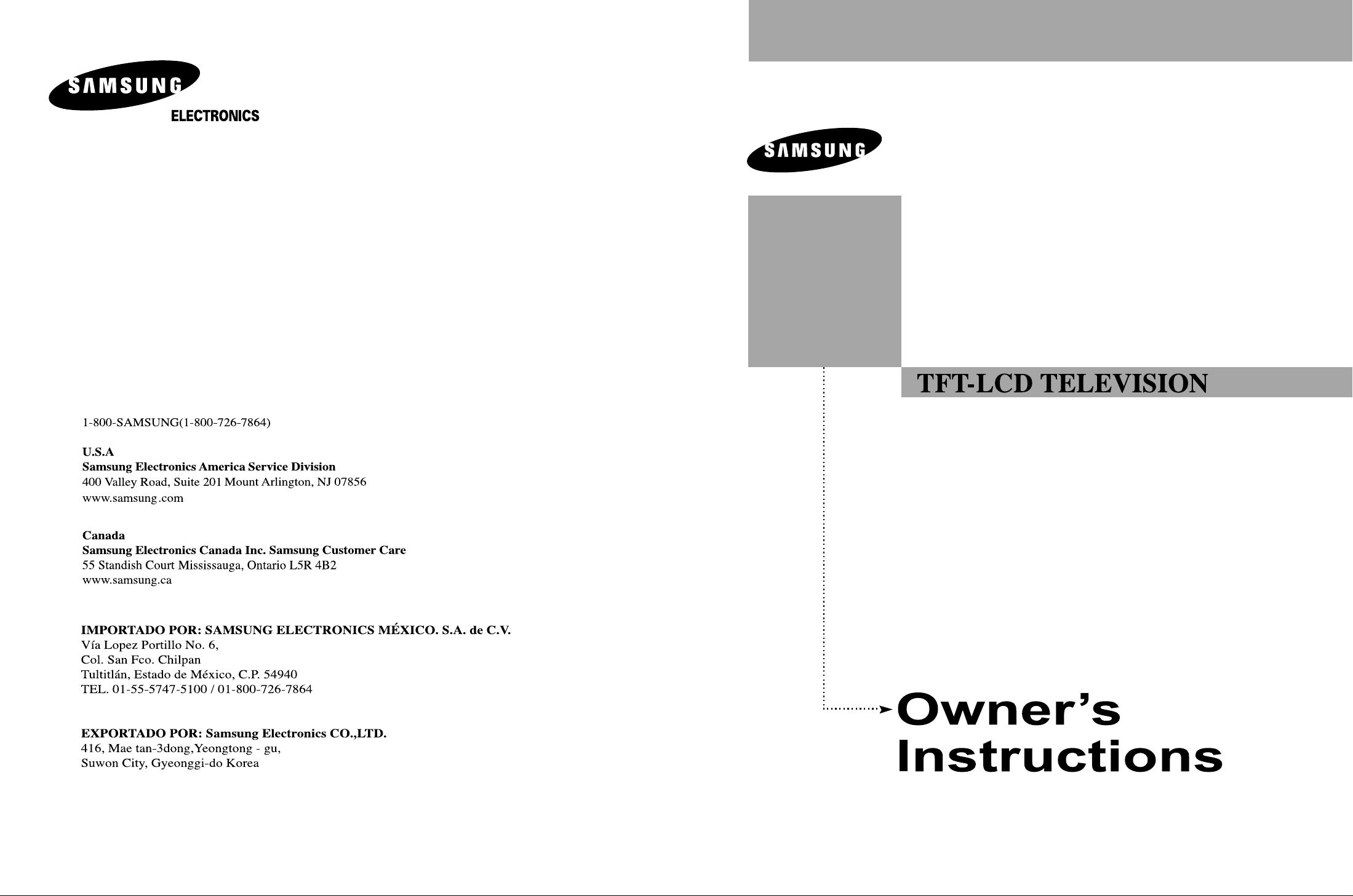
Precautions When Displaying a Still Image
A still image may cause permanent damage to the TV screen.
•
Digital Ready TV: When you
select the regular screen (4:3)
mode to watch an SD-grade
digital broadcast (and the Set-Top
Box output is 480p).
Although digital broadcasting must be in the
wide screen (16:9) HD format, broadcasters
sometimes show programs made originally
in the regular screen format (4:3) by
converting the signals into digital form, in
which case the left and right side edges of
the screen are cropped.
Do not leave the screen in pause mode for
extended periods of time as you may
experience temporary or permanent image
burn.
Note: If the borders at the left, right and the
center of the screen remain fixed for
an extended period of time, the
amount of light transmission will also
remain varied and as a result the
borders may leave traces.
•
Digital Ready TV: When you select
the wide screen (16:9) mode to
watch an SD-grade
digital broadcast (and the Set-Top
Box output is 1080i).
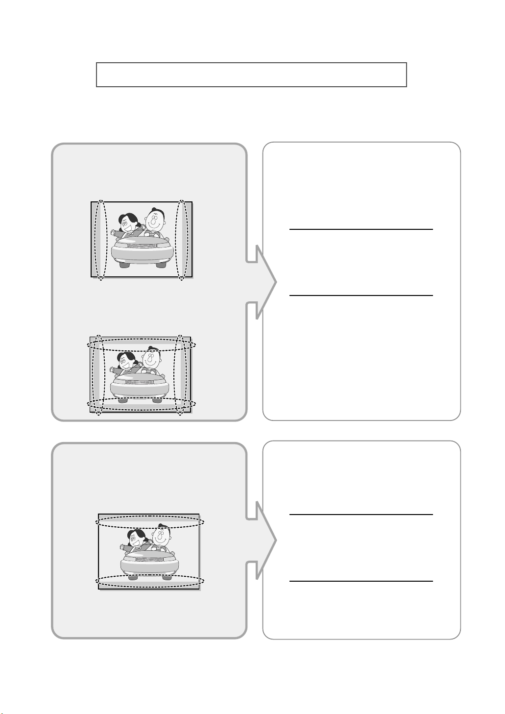
•
Digital Ready TV: When the
TV receives HD-grade signals
(and the Set-Top Box output is
1080i).
When you watch a digital HD-grade broadcast on a regular (4:3) TV with the screen
size "16:9" or "Panorama" selected, you will
be able to watch the program but the top and
bottom edges of the screen will be cropped.
Do not leave the screen in pause mode for
extended periods of time as you may
experience temporary or permanent image
burn.
Note: If the borders at the top, bottom and
the center of the screen remain fixed
for an extended period of time, the
amount of light transmission will also
remain varied and as a result the
borders may leave traces.
• Integrated
Digital TV
(Wide-screen): When the TV
receives SD-grade (regular)
broadcasting signals (receives
480p regular signals).
•
Digital Ready TV
(wide-screen):
digital TV: When the TV receives
SD-grade (regular) broadcasting
signals (with a Set-Top Box).
• When you watch an analog
(regular) broadcast on a
wide-screen TV (with the 4:3 screen
mode selected).
Although digital broadcasting must be in the
wide screen (16:9) HD format, broadcasters
sometimes show programs made originally
in the regular screen format (4:3) by
converting the signals into digital form, in
which case the left and right side edges of
the screen are cropped.
Do not leave the screen in pause mode for
extended periods of time as you may
experience temporary or permanent image
burn.
Note: If the borders at the left, right and the
center of the screen remain fixed for
an extended period of time, the
amount of light transmission will also
remain varied and as a result the
borders may leave traces.
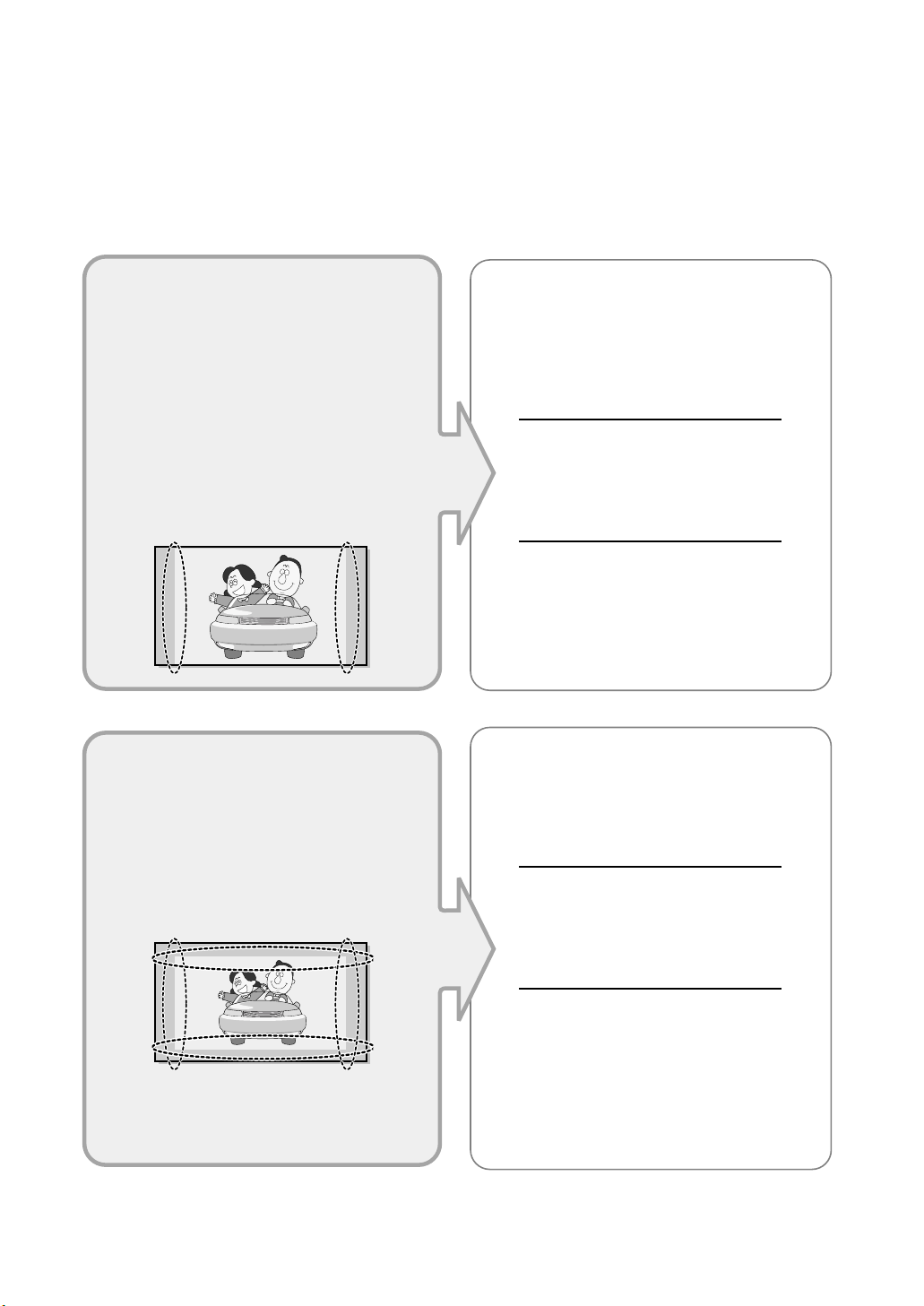
•
When you watch a DVD, CD or a
video in wide-screen (21:9) format
on a wide-screen (16:9) TV.
• When you connect a computer or a
game console to the TV and select
the 4:3 screen mode.
If you connect a DVD player, computer or a
game console to the wide-screen TV and
watch a movie or play a game in regular
(4:3) or wide (21:9) screen mode, the left
and right side edges, or the top and bottom
edges of the screen will be cropped.
Do not leave the screen in pause mode for
extended periods of time as you may
experience temporary or permanent image
burn.
Note: If the borders at the left, right and the
center of the screen remain fixed for
an extended period of time, the
amount of light transmission will also
remain varied and as a result the
borders may leave traces.

Contents-1
CONTENTS
Chapter 1: General Information
List of Features . . . . . . . . . . . . . . . . . . . . . . . . . . . . . . . . . . . . . . . . 1
List of Parts . . . . . . . . . . . . . . . . . . . . . . . . . . . . . . . . . . . . . . . . . . . 1
Familiarizing Yourself with Your New TV . . . . . . . . . . . . . . . . . . . . 2
Buttons on the Lower-Right Part of the Panel . . . . . . . . . . . . . . 2
Rear Panel Jacks . . . . . . . . . . . . . . . . . . . . . . . . . . . . . . . . . . . . 3
Side Panel Jacks
(LN-R329D, LN32M51BD, LN-R409D, LN40M51BD,
LN-R469D, LN46M51BD)
. . . . . . . . . . . . . . . . . . . . . . . . . . . . . . . . 4
Remote Control . . . . . . . . . . . . . . . . . . . . . . . . . . . . . . . . . . . . . . . . 5
Installing Batteries in the Remote Control . . . . . . . . . . . . . . . . . . . . . 7
If the remote control doesn’t work . . . . . . . . . . . . . . . . . . . . . . . . . . . 7
Chapter 2: Connections
Connecting VHF and UHF Antennas . . . . . . . . . . . . . . . . . . . . . . . . 8
Antennas with 300-ohm Flat Twin Leads . . . . . . . . . . . . . . . . . 8
Antennas with 75-ohm Round Leads . . . . . . . . . . . . . . . . . . . . 9
Separate VHF and UHF Antennas . . . . . . . . . . . . . . . . . . . . . . . 9
Connecting Cable TV . . . . . . . . . . . . . . . . . . . . . . . . . . . . . . . . . . . . 9
Cable without a Cable Box . . . . . . . . . . . . . . . . . . . . . . . . . . . . 9
Connecting to a Cable Box that Descrambles All Channels . . . 10
Connecting to a Cable Box that Descrambles Some Channels . 10
Connecting a VCR . . . . . . . . . . . . . . . . . . . . . . . . . . . . . . . . . . . . . 12
Connecting an S-VHS VCR . . . . . . . . . . . . . . . . . . . . . . . . . . . . . . 14
Connecting a Camcorder
(LN-R329D, LN32M51BD, LN-R409D,
LN40M51BD, LN-R469D, LN46M51BD)
. . . . . . . . . . . . . . . . . . . . . . . . 15
Connecting a DVD Player . . . . . . . . . . . . . . . . . . . . . . . . . . . . . . . 15
Connecting a DVD Player/Set-Top Box via DVI . . . . . . . . . . . . . . 16
Connecting a DVD Player/Set-Top Box via HDMI . . . . . . . . . . . . . 16
Connecting a Digital Audio System . . . . . . . . . . . . . . . . . . . . . . . . 17
Connecting an Amplifier/DVD Home Theater . . . . . . . . . . . . . . . . 17
Connecting a PC . . . . . . . . . . . . . . . . . . . . . . . . . . . . . . . . . . . . . . . 17
Connecting CableCARD
(LN-R409D, LN40M51BD, LN-R469D, LN46M51BD) .
18
Chapter 3: Operation
Turning the TV On and Off . . . . . . . . . . . . . . . . . . . . . . . . . . . . . . . 19
Changing Channels . . . . . . . . . . . . . . . . . . . . . . . . . . . . . . . . . . . . . 19
Using the Channel Buttons . . . . . . . . . . . . . . . . . . . . . . . . . . . 19
Using the PRE-CH Button to select the Previous Channel . . . . 19
Adjusting the Volume . . . . . . . . . . . . . . . . . . . . . . . . . . . . . . . . . . . 19
Using Mute . . . . . . . . . . . . . . . . . . . . . . . . . . . . . . . . . . . . . . . . 19
Viewing the Display . . . . . . . . . . . . . . . . . . . . . . . . . . . . . . . . . . . . 20
Viewing the Menus . . . . . . . . . . . . . . . . . . . . . . . . . . . . . . . . . . . . . 20
Plug & Play Feature . . . . . . . . . . . . . . . . . . . . . . . . . . . . . . . . . . . . 21
If you want to reset this feature... . . . . . . . . . . . . . . . . . . . . . . 24
Memorizing the Channels . . . . . . . . . . . . . . . . . . . . . . . . . . . . . . . . 25
Selecting the Video Signal-source . . . . . . . . . . . . . . . . . . . . . . 25
Storing Channels in Memory (Automatic Method) . . . . . . . . . 26
Adding and Erasing Channels (Manual Method) . . . . . . . . . . . 28
Setting Up Your Remote Control . . . . . . . . . . . . . . . . . . . . . . . . . . 29
Remote Control Codes . . . . . . . . . . . . . . . . . . . . . . . . . . . . . . 32
To Select the Source . . . . . . . . . . . . . . . . . . . . . . . . . . . . . . . . . . . . 33
To Edit the Input Source Name . . . . . . . . . . . . . . . . . . . . . . . . . . . . 35

Contents-2
CONTENTS
Chapter 4: Picture Control
Using Automatic Picture Settings . . . . . . . . . . . . . . . . . . . . . . . . . . 37
Adjusting the Color Tone . . . . . . . . . . . . . . . . . . . . . . . . . . . . . . . . 39
DNle (Digital Natural Image engine) . . . . . . . . . . . . . . . . . . . . . . . 40
Changing the Screen Size . . . . . . . . . . . . . . . . . . . . . . . . . . . . . . . . 41
Freezing the Picture . . . . . . . . . . . . . . . . . . . . . . . . . . . . . . . . . . . . 43
Viewing Picture-in-Picture . . . . . . . . . . . . . . . . . . . . . . . . . . . . . . . 44
Activating Picture-in-Picture . . . . . . . . . . . . . . . . . . . . . . . . . . 44
Selecting a Signal Source (External A/V) for PIP . . . . . . . . . . 45
Swapping the Contents of the PIP and Main image . . . . . . . . . 46
Changing the PIP Channel . . . . . . . . . . . . . . . . . . . . . . . . . . . 46
Changing the Position of the PIP Window . . . . . . . . . . . . . . . . 47
Changing the Size of the PIP Window . . . . . . . . . . . . . . . . . . . 47
My Color Control . . . . . . . . . . . . . . . . . . . . . . . . . . . . . . . . . . . . . . 48
Easy Control . . . . . . . . . . . . . . . . . . . . . . . . . . . . . . . . . . . . . . 48
Detail Control . . . . . . . . . . . . . . . . . . . . . . . . . . . . . . . . . . . . . 49
Dynamic Contrast . . . . . . . . . . . . . . . . . . . . . . . . . . . . . . . . . . . . . . 50
Brightness Sensor . . . . . . . . . . . . . . . . . . . . . . . . . . . . . . . . . . . . . . 51
Chapter 5: Sound Control
Customizing the Sound . . . . . . . . . . . . . . . . . . . . . . . . . . . . . . . . . . 52
Using Automatic Sound Settings . . . . . . . . . . . . . . . . . . . . . . . . . . 53
Setting the Trusurround XT . . . . . . . . . . . . . . . . . . . . . . . . . . . . . . 54
Choosing a Multi-Channel Sound(MTS) track - Digital . . . . . . . . . 55
Preferred Language . . . . . . . . . . . . . . . . . . . . . . . . . . . . . . . . . 55
Multi-Track Sound . . . . . . . . . . . . . . . . . . . . . . . . . . . . . . . . . 56
Automatic Volume Control . . . . . . . . . . . . . . . . . . . . . . . . . . . . . . . 57
Selecting the Internal Mute . . . . . . . . . . . . . . . . . . . . . . . . . . . . . . 58
Choosing a Digital Sound Format . . . . . . . . . . . . . . . . . . . . . . . . . . 59
Setting the On/Off Melody . . . . . . . . . . . . . . . . . . . . . . . . . . . . . . . 60
Chapter 6: Channel Control
Selecting the Antenna . . . . . . . . . . . . . . . . . . . . . . . . . . . . . . . . . . . 61
To Set-up Your Favorite Channels . . . . . . . . . . . . . . . . . . . . . . . . . . 62
Labeling Channels . . . . . . . . . . . . . . . . . . . . . . . . . . . . . . . . . . . . . . 63
Viewing the Channel Lists . . . . . . . . . . . . . . . . . . . . . . . . . . . . . . . 64
Editing the Channel Lists . . . . . . . . . . . . . . . . . . . . . . . . . . . . . . . 65
Fine Tuning Analog Channels . . . . . . . . . . . . . . . . . . . . . . . . . . . . 66
Checking the Digital-Signal Strength . . . . . . . . . . . . . . . . . . . . . . 67
LNA (Low Noise Amplifier) . . . . . . . . . . . . . . . . . . . . . . . . . . . . . . 68
Chapter 7: PC Display
Using Your TV as a Computer (PC) Display . . . . . . . . . . . . . . . . . . 69
Setting Up Your PC Software (Based on Windows XP) . . . . . . 69
How to Auto Adjust . . . . . . . . . . . . . . . . . . . . . . . . . . . . . . . . 70
Adjusting the Screen Quality . . . . . . . . . . . . . . . . . . . . . . . . . 71
Changing the Screen Position . . . . . . . . . . . . . . . . . . . . . . . . . 73
Initializing the Screen Position or Color Settings . . . . . . . . . . 75

Contents-3
CONTENTS
Chapter 8: Time Setting
Setting the Clock . . . . . . . . . . . . . . . . . . . . . . . . . . . . . . . . . . . . . . 76
Option 1:Setting the Clock Manually . . . . . . . . . . . . . . . . . . . 76
Option 2:Setting the Clock Automatically . . . . . . . . . . . . . . . . 78
Setting the Sleep Timer . . . . . . . . . . . . . . . . . . . . . . . . . . . . . . 80
Setting the On/Off Timer . . . . . . . . . . . . . . . . . . . . . . . . . . . . 81
Chapter 9: Function Description
Selecting a Menu Language . . . . . . . . . . . . . . . . . . . . . . . . . . . . . . 82
Selecting the Film Mode . . . . . . . . . . . . . . . . . . . . . . . . . . . . . . . . . 83
Digital Noise Reduction . . . . . . . . . . . . . . . . . . . . . . . . . . . . . . . . . 84
Using the Color Weakness Enhancement Option . . . . . . . . . . . . . . . 85
Viewing Closed Captions (On-Screen Text Messages) - Analog . . . 87
Viewing Closed Captions (On-Screen Text Messages) - Digital . . . 89
Menu Transparency Level . . . . . . . . . . . . . . . . . . . . . . . . . . . . . . . 92
Setting the Function Help . . . . . . . . . . . . . . . . . . . . . . . . . . . . . . . . 93
Using the V-Chip . . . . . . . . . . . . . . . . . . . . . . . . . . . . . . . . . . . . . . 95
Setting Up Your Personal ID Number(PIN) . . . . . . . . . . . . . . . 95
How to Enable/Disable the V-Chip . . . . . . . . . . . . . . . . . . . . . 96
How to Set up Restrictions Using the
“TV Parental Guidelines” . . . . . . . . . . . . . . . . . . . . . . . . . . . . . .97
How to Set up Restrictions Using the MPAA Ratings:
G, PG, PG-13, R, NC-17, X, NR . . . . . . . . . . . . . . . . . . . . . . . 99
How to Set up Restrictions Using the ‘Canadian English’ . . . 101
How to Set up Restrictions Using the ‘Canadian French’ . . . 102
How to Reset the TV after the V-Chip Blocks a Channel
(“Emergency Escape”) . . . . . . . . . . . . . . . . . . . . . . . . . . . . . 103
Electronic Program Guide . . . . . . . . . . . . . . . . . . . . . . . . . . . . . . . 104
Viewing the Electronic Program Guide . . . . . . . . . . . . . . . . . 104
Using the Electronic Program Guide . . . . . . . . . . . . . . . . . . . 105
Viewing Information about a Single Channel . . . . . . . . . . . . 106
Viewing Information about Channels . . . . . . . . . . . . . . . . . . 107
Remind List . . . . . . . . . . . . . . . . . . . . . . . . . . . . . . . . . . . . . . . . . 109
Viewing the Remind List . . . . . . . . . . . . . . . . . . . . . . . . . . . 109
To View the Remind List . . . . . . . . . . . . . . . . . . . . . . . . . . . . 110
To Remove the Scheduled Programs . . . . . . . . . . . . . . . . . . . 110
Using the CableCARD (Sold separately)
(LN-R409D, LN40M51BD,
LN-R469D, LN46M51BD)
. . . . . . . . . . . . . . . . . . . . . . . . . . . . . . . . . . 111
Displaying CableCARD related information . . . . . . . . . . . . . 111
Using the CableCARD Setup Function
(LN-R409D, LN40M51BD,
LN-R469D, LN46M51BD)
. . . . . . . . . . . . . . . . . . . . . . . . . . . . . . . . . . 112
CableCARD Reset . . . . . . . . . . . . . . . . . . . . . . . . . . . . . . . . 112
Channel List Reorganization . . . . . . . . . . . . . . . . . . . . . . . . . 113
Chapter 10: Appendix
Identifying Problems . . . . . . . . . . . . . . . . . . . . . . . . . . . . . . . . . . 114
Installing the Stand
(LN-R269D, LN-R329D, LN32M51BD)
. . . . . . . . . 116
Disconnecting the Stand . . . . . . . . . . . . . . . . . . . . . . . . . . . . . . . . 116
Installing the Wall Mount Kit
(LN-R269D)
. . . . . . . . . . . . . . . . . . . 117
Installing the Wall Mount Kit
(LN-R329D, LN32M51BD, LN-R409D,
LN40M51BD, LN-R469D, LN46M51BD)
. . . . . . . . . . . . . . . . . . . . . . . . 118
Using the Anti-Theft Kensington Lock . . . . . . . . . . . . . . . . . . . . . 119
Using Your TV in Another Country . . . . . . . . . . . . . . . . . . . . . . . . 119
CableCARD and Digital Cable Ready TVs . . . . . . . . . . . . . . . . . . 120
Specifications . . . . . . . . . . . . . . . . . . . . . . . . . . . . . . . . . . . . . . . . 121
Display Modes . . . . . . . . . . . . . . . . . . . . . . . . . . . . . . . . . . . . . . . 123
English-1
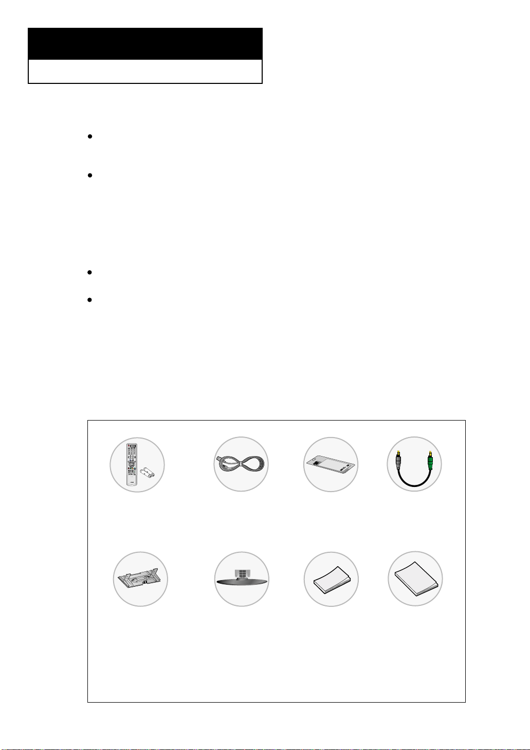
List of Parts
Please make sure the following items are included with your LCD TV.
If any items are missing, contact your dealer.
List of Features
Excellent Digital Interface & Networking :
With a built-in HD digital tuner, this TV supports HD broadcasts with no
Set-Top Box needed, and provides simple access with a single remote control.
Excellent Picture Quality
- DNIe technology provides life-like clear images.
-
My Color Control: Colors can be set to your preference by adjusting Red, Green, Blue,
Yellow, Pink, and White.
- Dynamic Contrast: Automatically detects the input visual signal and adjusts to create
optimum contrast.
- Brightness Sensor: Adjusts the screen brightness automatically depending on the
brightness of the surrounding environment.
SRS TruSurround XT
- SRS TruSurround XT provides a virtual Dolby surround system.
Convenience
- The TV utilizes the HDMI system to implement perfect digital sound and picture quality.
- The Anynet system enables you to easily control Samsung audio-video (AV) devices
from this TV.
- For more information about Anynet, refer to the Anynet AV Owner’s Instructions.
Chapter 1
GENERAL INFORMATION
Owner’s
Instructions
Power Cord
(3903-000085)
Cleaning Cloth
(BN63-001798A)
Remote Control
(BN59-00460A)
& Batteries (AAA x 2)
Stand
LN-R269D:
BN96-02203A
LN-R329D/
LN32M51BD
:
BN96-02202A
Anynet Cable
(BN39-00518B)
Cover-Bottom
LN-R269D/LN-R329D/
LN32M51BD: BN63-01947A
LN-R409D/LN40M51BD:
BN63-01938A
LN-R469D/LN46M51BD:
BN63-01810A
Anynet AV
Owner’s
Instructions
English-2
Familiarizing Yourself with Your New TV
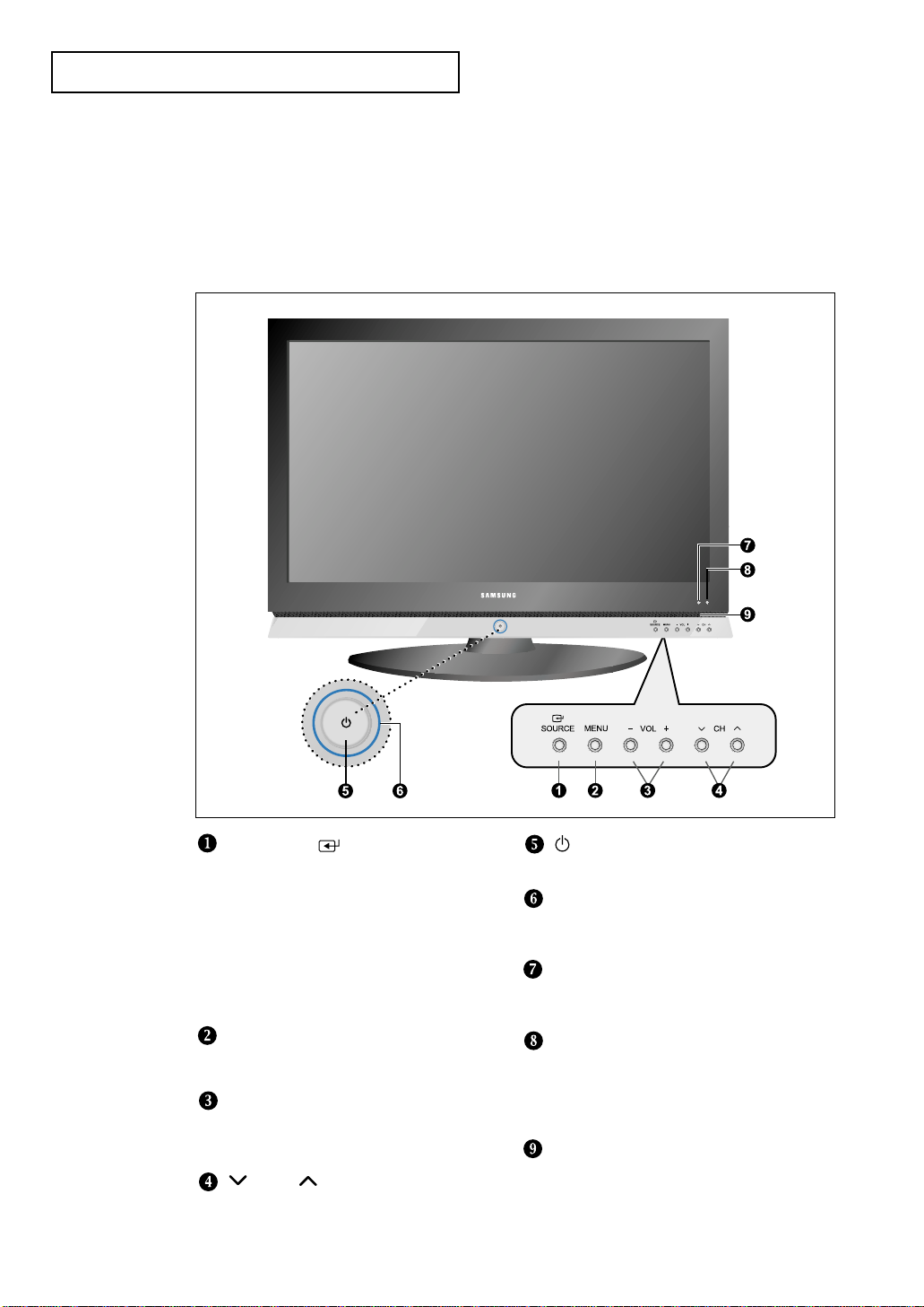
Buttons on the Lower-Right Part of the Panel
The buttons on the lower-right panel control your TV’s basic features, including the
on-screen menu. To use the more advanced features, you must use the remote control.
GENERAL INFORMATION
SOURCE
Displays a menu of all of the available
input sources.
• LN-R269D
- TV, AV, S-VIDEO, Component 1, Component 2,
PC, HDMI
• LN-R329D / LN32M51BD / LN-R409D / LN40M51BD /
LN-R469D / LN46M51BD
- TV, AV 1, AV 2, S-VIDEO 1, S-VIDEO 2,
Component 1, Component 2, PC, HDMI
Also used to confirm your choice on the
on-screen menu.
MENU
Press to see an on-screen menu of
your TV’s features.
–
VOL +
Press to decrease or increase the volume.
Also used to select items on the
on-screen menu.
CH
Press to change channels.
Also press to highlight various items
on the on-screen menu.
(POWER)
Press to turn the TV on and off.
POWER INDICATOR
Blinks and turns off when the power is on and
lights up in stand-by mode.
REMOTE CONTROL SENSOR
Aim the remote control towards this spot
on the TV.
LIGHT DETECTING SENSOR
Adjusts the brightness of the screen
automatically by detecting brightness of the
surrounding environment. This sensor works
when the Brightness Sensor is on.
SPEAKERS
English-3
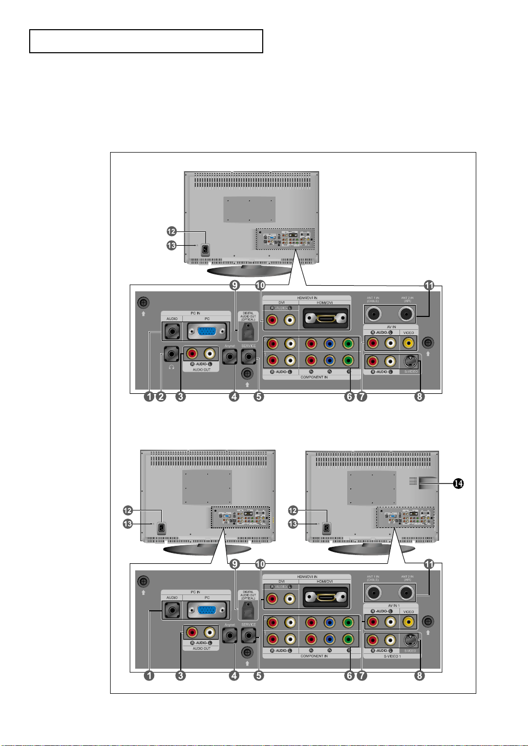
GENERAL INFORMATION
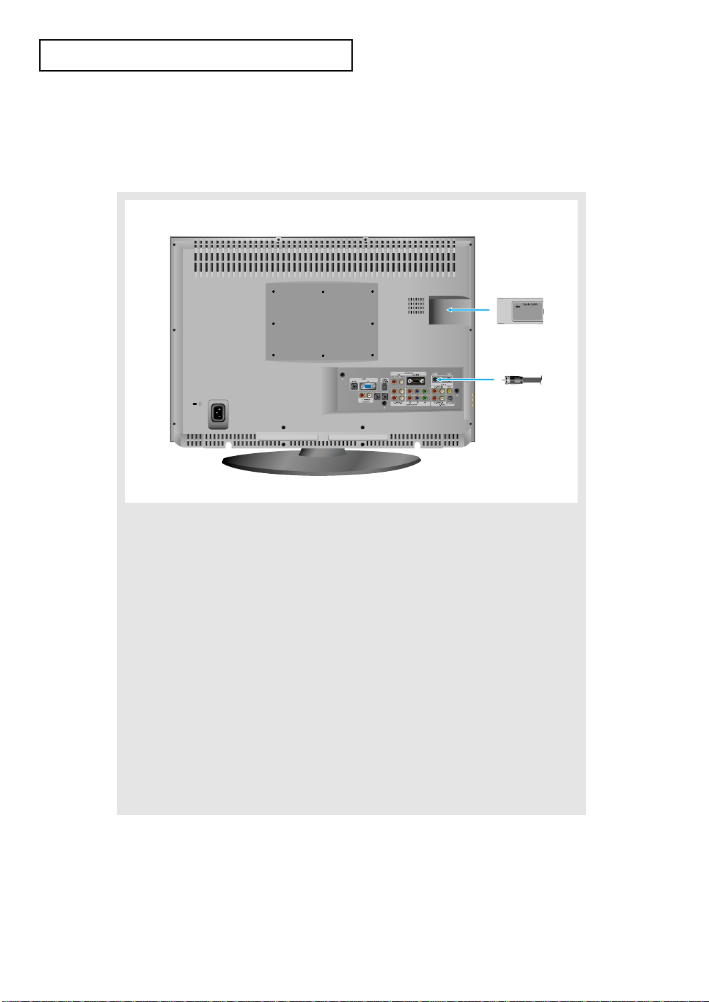
Rear Panel Jacks
Use the rear panel jacks to connect an A/V component that will be connected
continuously, such as a VCR or a DVD player.
For more information on connecting equipment, see pages 8-18.
The TV surface can be different depending on the model.
LN-R269D
LN-R409D/ LN40M51BD / LN-R469D / LN46M51BD
LN-R329D / LN32M51BD
English-4
PC IN
Connect to the video and audio output jacks
on your PC.
HEADPHONE
(LN-R269D)
Connect a set of external headphones for
private
listening.
AUDIO OUT
Connect to the audio input jacks on your
Amplifier/Home theater.
Anynet
Refer to “Anynet AV Owner’s Instructions”.
SERVICE
Connector for service only.
COMPONENT IN
Connect component video/audio from a
DVD/Set-Top Box.
AV IN (1)
Video and audio inputs for external
devices, such as a camcorder or VCR.
S-VIDEO IN (1)
Video inputs for external devices with an
S-Video output, such as a camcorder or VCR.
DIGITAL AUDIO OUT (OPTICAL)
Connect to a Digital Audio component.
HDMI/DVI IN
Connect to the HDMI jack of a device with an HDMI
output. Use the HDMI/DVI
terminal for DVI connection to an
external device. You should use the
DVI to HDMI cable or DVI-HDMI
adapter (DVI to HDMI) for the connection,
and the 'R -AUDIO -L' terminal on DVI-IN for
sound output.
-
HDMI/DVI IN terminal does not support PC.
- No sound connection is needed for an
HDMI to HDMI connection.
ANT IN
Connect to an antenna or to a cable TV system.
(See pages 8-11, 61)
POWER INPUT
Connect the supplied power cord.
KENSINGTON LOCK
Refer to “Using the Anti-Theft Kensington
Lock” on page 119.
CABLE CARD
(
(
LN-R409D/LN40M51BD/
LN-R469D/LN46M51BD
)
Insert the cableCARD into the slot.
Speaker Audio Out
RF AV, S-Video
Component, PC, HDMI
RF
AV, S-VIDEO Component, PC, HDMI
Internal Mute Off
Speaker Output Speaker Output Speaker Output Sound Output Sound Output Sound Output
Internal Mute On
Mute Mute Mute Sound Output Sound Output Sound Output
Video No Signal
Mute Mute Mute Mute Sound Output Sound Output
When “Internal mute” is set to “On”, Sound menus except “Multi-Track Options” and “Digital Output” cannot be adjusted.
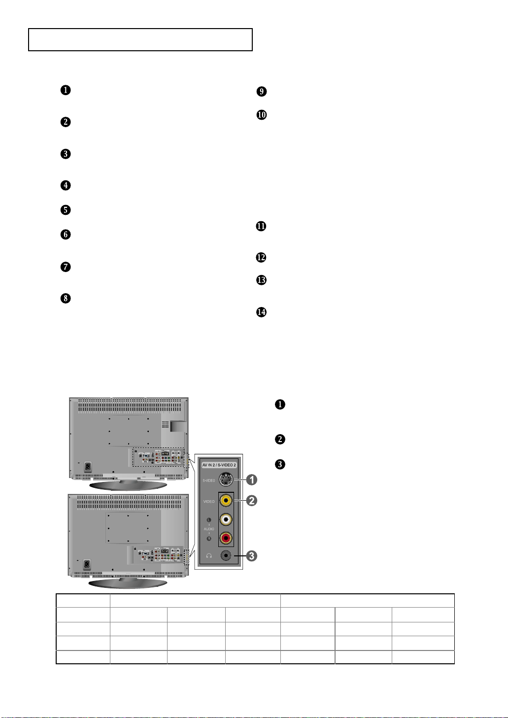
GENERAL INFORMATION
Side Panel Jacks
(LN-R329D, LN32M51BD, LN-R409D, LN40M51BD, LN-R469D, LN46M51BD )
Use the left side panel jacks to connect a component that is used only occasionally,
such as a camcorder or video game. (See page 15)
S-VIDEO IN (2)
Video inputs for external devices with an
S-Video output.
AV IN (2)
Video and audio inputs for external devices.
HEADPHONE
Connect a set of external headphones for
private
listening.
English-5
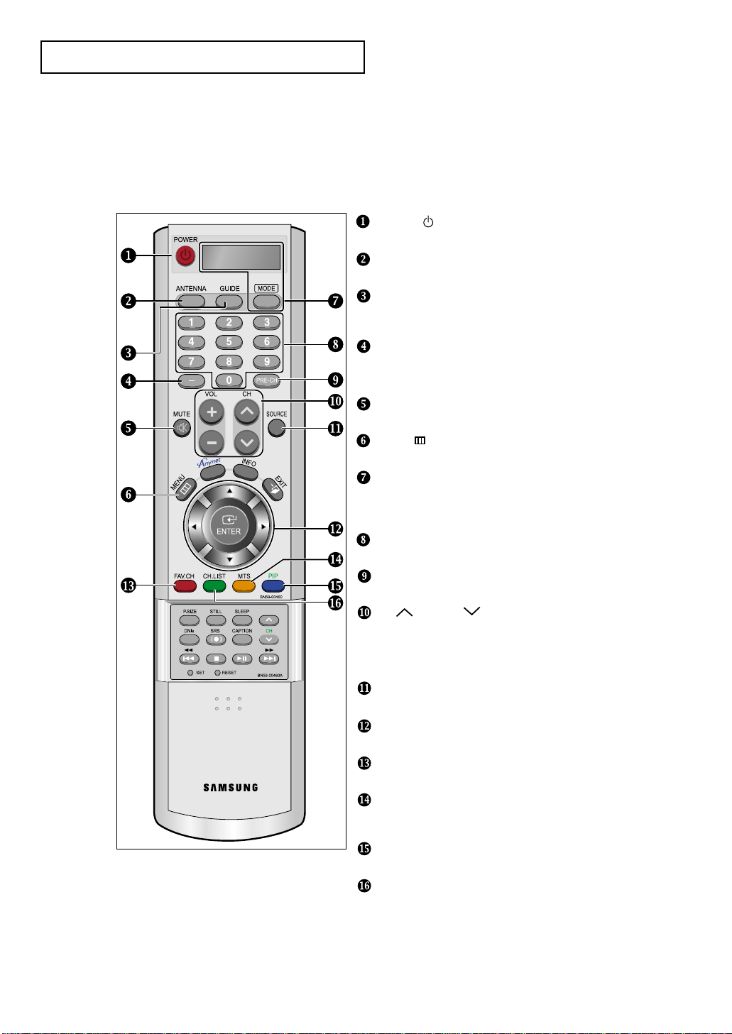
GENERAL INFORMATION
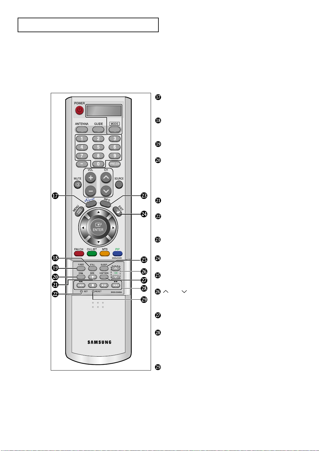
Remote Control
POWER
Turns the TV on and off. (See page 19)
ANTENNA
Press to select “AIR” or “CABLE”. (See pages 8~11)
GUIDE
Press to display the on-screen Electronic Program Guide (EPG).
(See page 104)
-
Press to select additional channels (digital and analog) being
broadcast by the same station. For example, to select channel
“54-3”, press “54”, then press “-” and “3”.
MUTE
Press to temporarily cut off the sound. (See page 19)
MENU
Displays the main on-screen menu. (See page 20)
MODE
Selects a target device to be controlled by the Samsung
remote control (TV, VCR, CATV, DVD, STB).
(See pages 29~31)
NUMERIC BUTTONS
Press to change the channel.
PRE-CH
Turns to the previous channel. (See page 19)
CH and CH (Channel UP/Down)
Press to change channels. (See page 19)
VOL + and VOL -
Press to increase or decrease the volume. (See page 19)
SOURCE
Press to display all of the available video sources.
UP / DOWN / LEFT / RIGHT / ENTER
Use to select on-screen menu items and change menu values.
FAV.CH
Press to switch to your favorite channels. (See page 62)
MTS
Press to choose stereo, mono or Separate Audio Program
(SAP broadcast). (See pages 55~56)
PIP
Picture-in Picture ON/OFF. (See page 44)
CH.LIST
Displays the channel list. (See page 64)
You can use the remote control up to a distance of about 23 feet from the TV. When using the
remote, always point it directly at the TV. You can also use your remote control to operate
your VCR, Cable box, DVD player, or Set-Top Box.
English-6
GENERAL INFORMATION
Anynet
Press the Anynet button to bring up the Anynet menu.
Refer to “Anynet AV Owner’s Instructions”.
STILL
Press to stop the action during a particular scene.
Press again to resume normal video. (See page 43)
P.SIZE
Press to change the screen size. (See page 41~42)
DNIe
Off : DNIe Demo mode is deactivated.
On : The right-hand side of the screen shows the improved DNIe
image.
The left-hand side of the screen shows the original image.
(See page 40)
SRS
Selects TruSurround XT mode. (See page 54)
SET
Adjusts 5 separate devices -
TV, VCR, Cable, DVD, or
Set-Top Box
. (See pages 29~31)
INFO
Use to see information on the current broadcast. (See page 20)
EXIT
Press to exit the menu.
SLEEP
Press to select a preset time interval for automatic shut off.
CH
Displays the available channels in sequence. (These buttons
change channels in the PIP window only.) (See page 46)
CAPTION
Controls the caption decoder. (See pages 87~91)
VCR/DVD Functions (Anynet mode only)
- Rewind
- Stop
- Play/Pause
- Fast/Forward
RESET
When your remote does not work, change the batteries and
press the RESET button for 2-3 seconds before use.
English-7
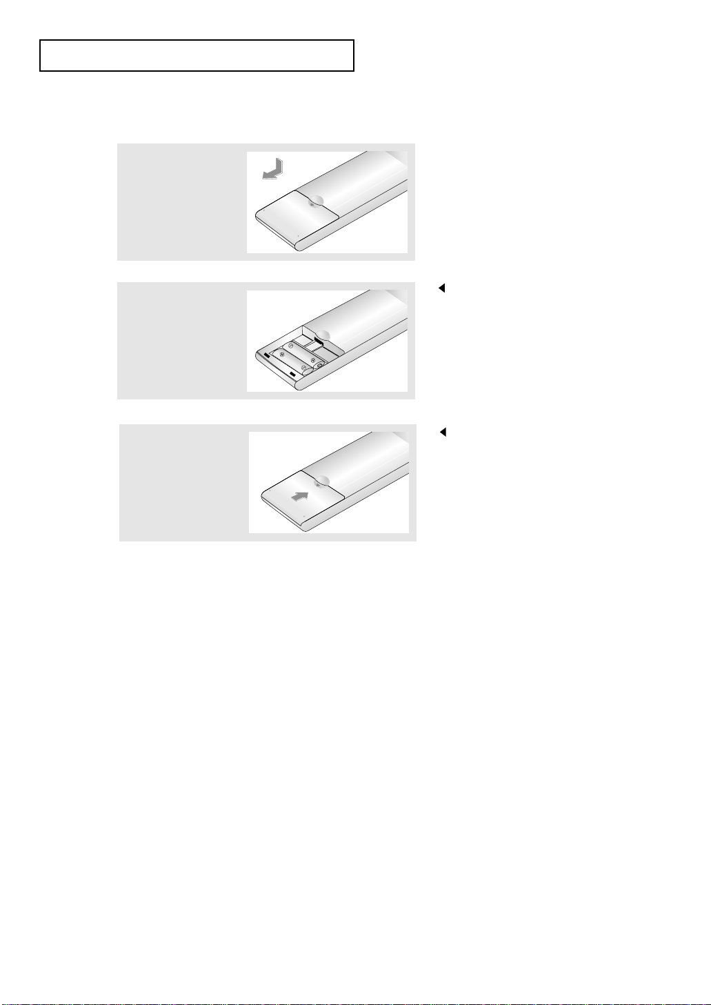
3
Replace the cover.
Remove the batteries and store them
in a cool, dry place if you won’t be
using the remote control for a long
time.
The remote control can be used
up to about 23 feet from the TV.
(Assuming typical TV usage,
the batteries last for about one year.)
2
Install two AAA size
batteries.
Make sure to match the “+” and
“
–” ends of the batteries with the
diagram inside the compartment.
Installing Batteries in the Remote Control
1
Slide the Cover out
completely.
GENERAL INFORMATION
If the remote control doesn’t work
Check the following:
1. Is the TV power on?
2. Are the plus and minus ends of the batteries reversed?
3. Are the batteries drained?
4. Is there a power outage, or is the power cord unplugged?
5. Is there a special fluorescent light or a neon sign nearby?
English-8
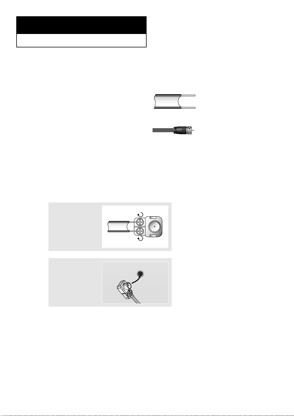
Connecting VHF and UHF Antennas
If your antenna has a set of leads that
look like this, see “Antennas with
300-ohm Flat Twin Leads” below.
If your antenna has one lead that looks
like this, see “Antennas with 75-ohm
Round Leads” on page 9.
If you have two antennas, see “Separate
VHF and UHF Antennas” on page 9.
Antennas with 300-ohm Flat Twin Leads
If you are using an off-air antenna (such as a roof antenna or “rabbit ears”) that has
300-ohm twin flat leads, follow the directions below.
Chapter 2
CONNECTIONS
1
Place the wires from
the twin leads under
the screws on a
300-75 ohm adapter
(not supplied). Use a
screwdriver to tighten
the screws.
2
Plug the adaptor into
the ANT 1 IN
(CABLE) terminal on
the back of the TV.
ANT 1 IN
(CABLE)
English-9
Connecting Cable TV
To connect to a cable TV system, follow the instructions below.
Cable without a Cable Box
1
Plug the incoming
cable into the
ANT 1 IN (CABLE)
terminal on the
back of the TV.
Because this TV is cable-ready,
you do not need a cable box to
view unscrambled cable channels.
2
Plug the combiner
into the ANT 2 IN
(AIR) terminal on
the bottom of the
rear panel.
Antennas with 75-ohm Round Leads
1
Plug the antenna
lead into the ANT 2 IN
(AIR) terminal on the
back of the TV.
Separate VHF and UHF Antennas
If you have two separate antennas for your TV (one VHF and one UHF), you must
combine the two antenna signals before connecting the antennas to the TV. This
procedure requires an optional combiner-adaptor (available at most electronics shops).
1
Connect both antenna
leads to the combiner.
CONNECTIONS
ANT 2 IN
(AIR)
UHF
VHF
ANT 2 IN
(AIR)
UHF
VHF
ANT 1 IN
(CABLE)
English-10
CONNECTIONS
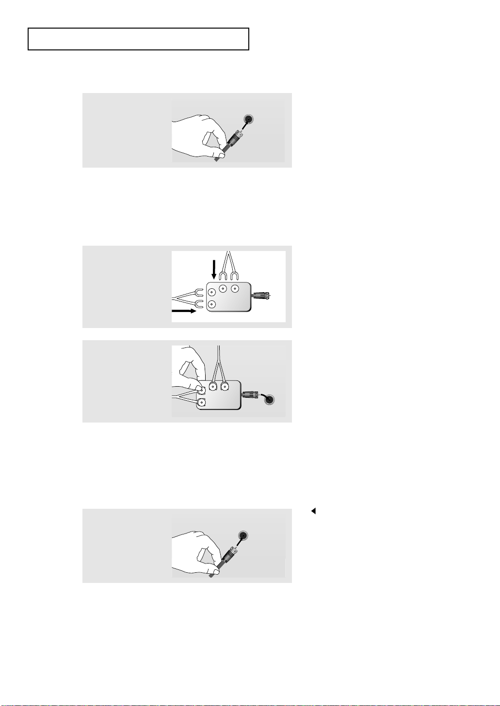
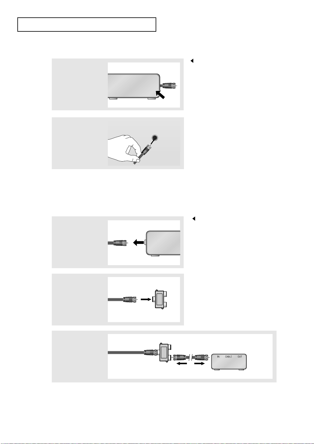
Connecting to a Cable Box that Descrambles All Channels
1
Find the cable that is
connected to the
ANT OUT terminal
on your cable box.
This terminal might be labeled
“ANT OUT”, “VHF OUT” or
simply, “OUT”.
2
Connect the other end
of this cable to the
ANT 1 IN (CABLE)
terminal on the back
of the TV.
Connecting to a Cable Box that Descrambles Some Channels
If your cable box descrambles only some channels (such as premium channels), follow the
instructions below. You will need a two-way splitter, an RF (A/B) switch, and four lengths
of RF cable. (These items are available at most electronics stores.)
1
Find and disconnect
the cable that is
connected to the
ANT IN terminal
on your cable box.
This terminal might be labeled
“ANT IN”, “VHF IN” or simply, “IN”.
2
Connect this cable
to a two-way splitter.
3
Connect an RF
cable between an
OUTPUT terminal on
the splitter and the IN
terminal on the cable
box.
ANT IN
ANT OUT
ANT 1 IN
(CABLE)
ANT IN
Incoming
cable
Splitter
Incoming
cable
Splitter
Cable Box
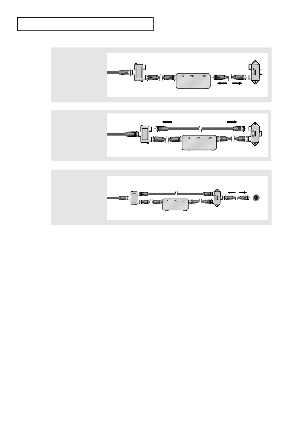
English-11
CONNECTIONS
4
Connect an RF
cable between the
ANT OUT terminal
on the cable box
and the B–IN
terminal on the
RF(A/B) switch.
5
Connect another
cable between the
other OUT terminal
on the splitter and
the A–IN terminal on
the RF (A/B) switch.
6
Connect the last
RF cable between the
OUT terminal on the
RF (A/B) switch and
the ANT 1 IN (CABLE)
terminal on the rear
of the TV.
After you have made this connection, set the A/B switch to the “A” position for normal
viewing. Set the A/B switch to the “B” position to view scrambled channels.
(When you set the A/B switch to “B”, you will need to tune your TV to the cable box’s
output channel, which is usually channel 3 or 4.)
Incoming
cable
Splitter
Cable Box
Incoming
cable
Incoming
cable
Splitter
Splitter
Cable Box
Cable Box
RF (A/B)
Switch
RF (A/B)
Switch
RF (A/B)
Switch
TV Rear
ANT 1IN
(CABLE)
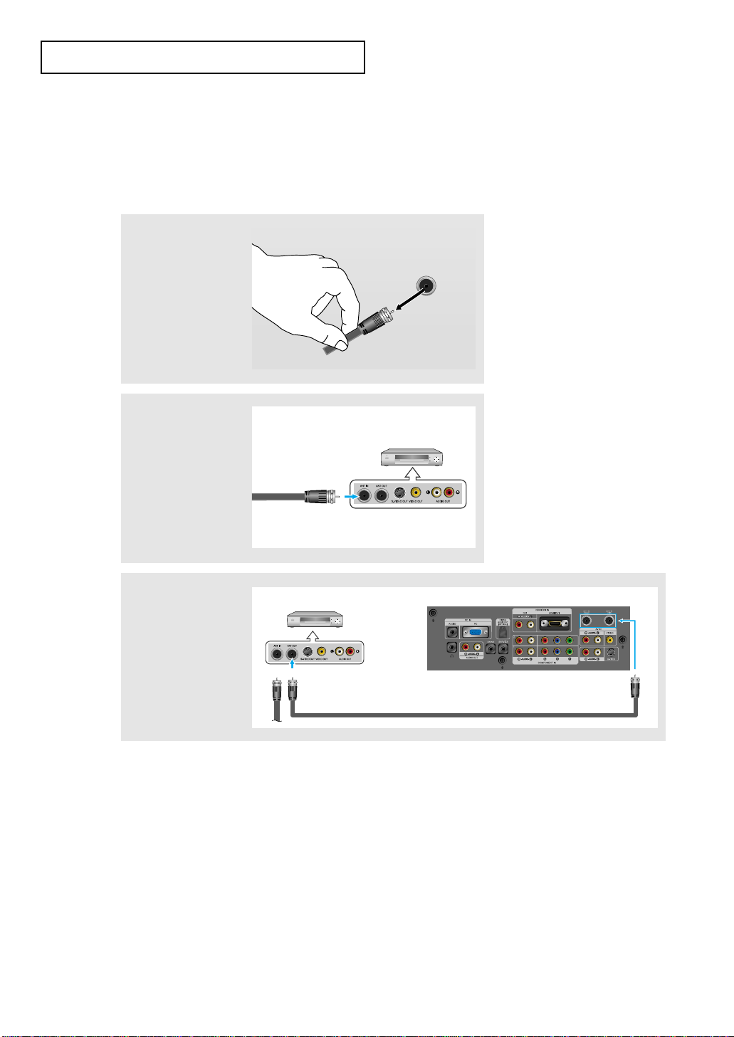
English-12
CONNECTIONS
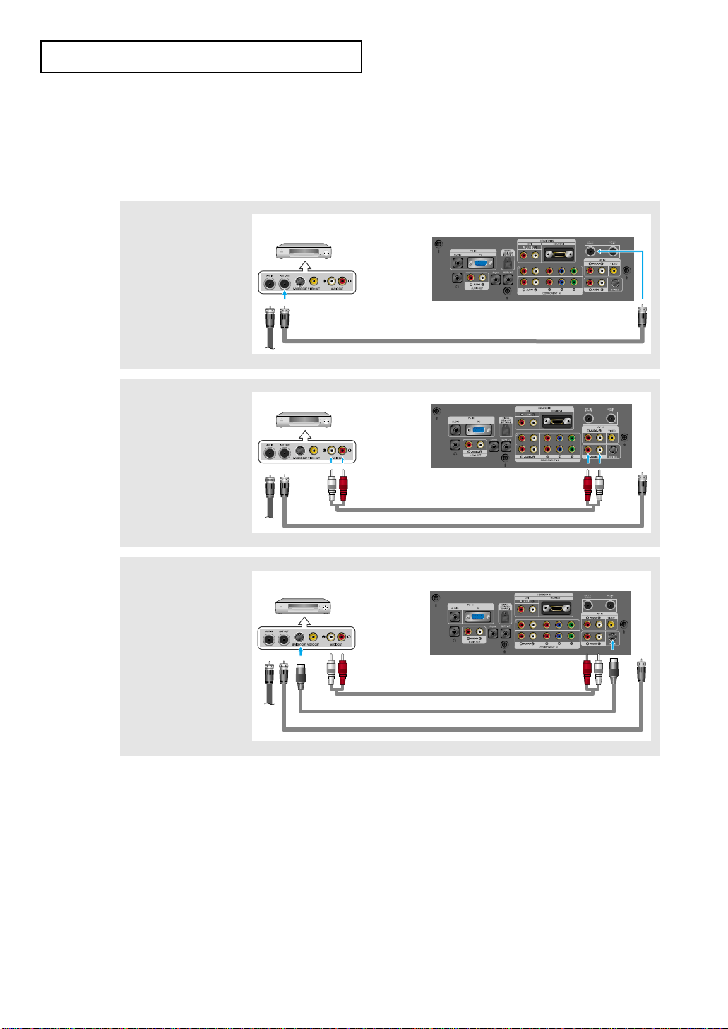
3
Connect an RF cable
between the
ANT OUT terminal
on the VCR and the
ANT 1 IN (CABLE)
or ANT 2 IN (AIR)
terminal on the TV.
Connecting a VCR
These instructions assume that you have already connected your TV to an antenna or a
cable TV system (according to the instructions on pages 8-11).
Skip step 1 if you have not yet connected to an antenna or a cable system.
1
Unplug the cable or
antenna from the
back of the TV.
2
Connect the cable or
antenna to the
ANT IN terminal
on the back of the
VCR.
VCR Rear Panel
Incoming Cable
or Antenna
TV Rear Panel
RF Cable (Option)
VCR Rear Panel
ANT IN
English-13
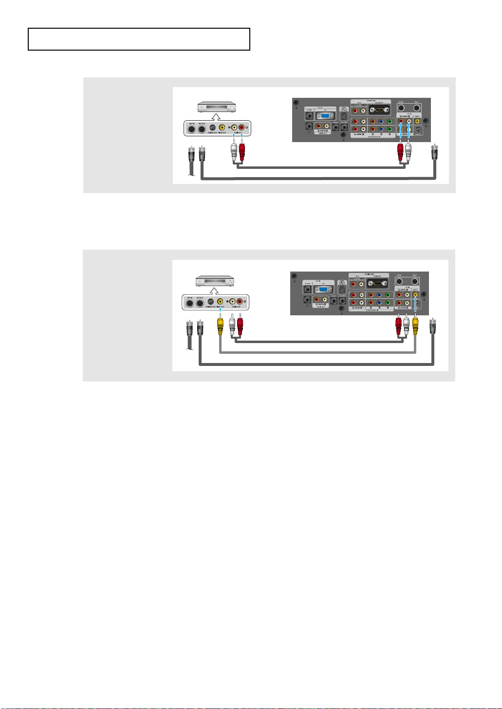
CONNECTIONS
4
Connect an audio
cable between the
AUDIO OUT jacks on
the VCR and the
AV IN [R-AUDIO-L
]
jacks on the TV.
5
Connect a video
cable between the
VIDEO OUT jack on
the VCR and the
AV IN [VIDEO]jack
on the TV.
Follow the instructions in “Viewing a VCR or Camcorder Tape” to view your VCR tape.
* Each external input source device has a different back panel configuration.
If you have a “mono” (non-stereo) VCR, use the Y-connector (not supplied) to hook
up to the right and left audio input jacks of the TV. If your VCR is stereo, you must
connect two cables.
TV Rear Panel
RF Cable (Option)
Audio Cable (Option)
VCR Rear Panel
TV Rear Panel
RF Cable (Option)
Audio Cable (Option)
VCR Rear Panel
Video Cable (Option)
* When connecting an external device, match the color of the connection terminal to the cable.
English-14
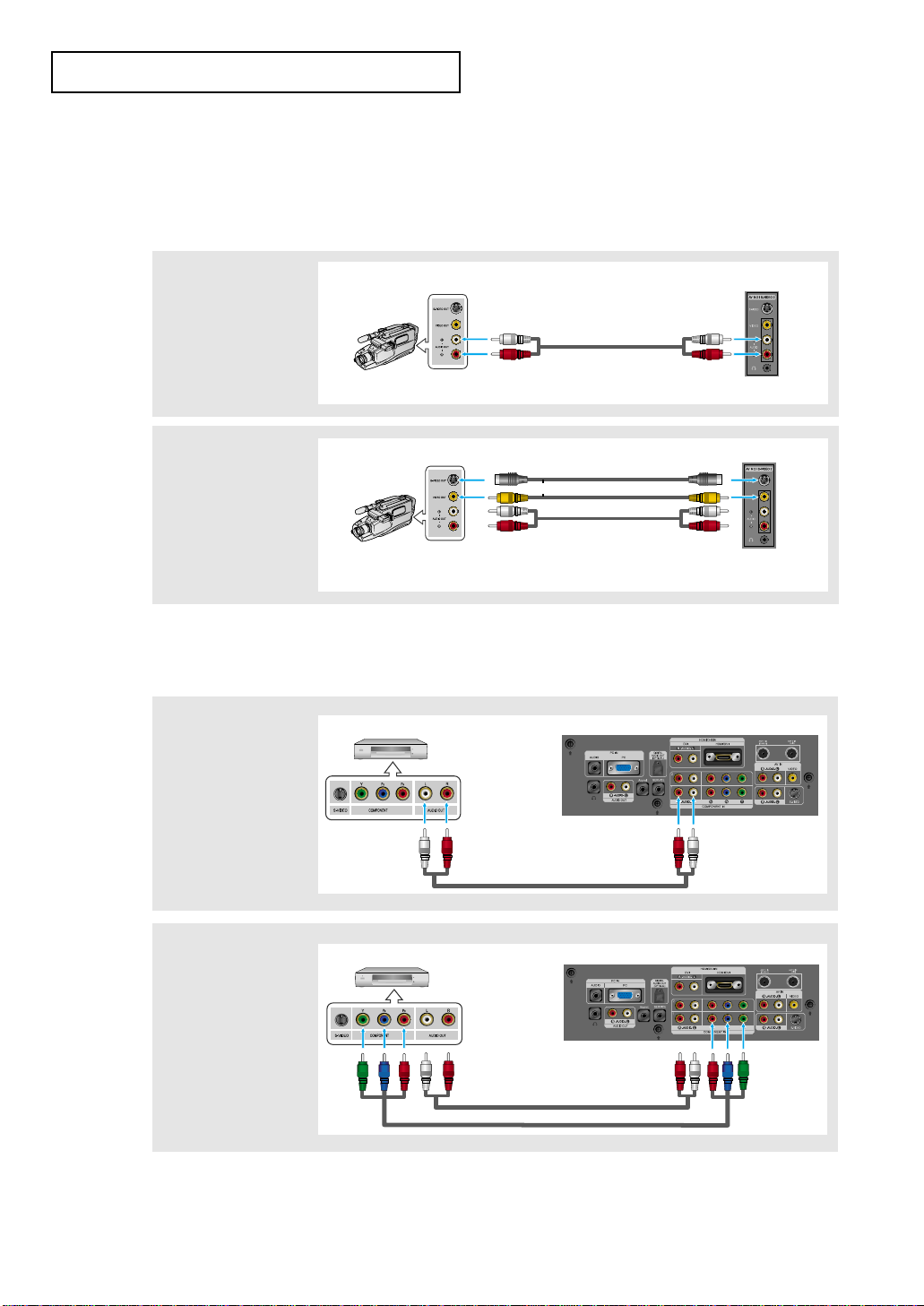
3
Connect an S-video
cable between the
S-VIDEO OUT jack on
the VCR and the
AV IN [S-VIDEO]jack
on the TV.
An S-Video cable is usually included with an S-VHS VCR.
(If not, check your local electronics store.)
* Each external input source device has a different back panel configuration.
1
To begin, follow
steps 1–3 in the
previous section to
connect the antenna
or cable to your
VCR and your TV.
Connecting an S-VHS VCR
Your Samsung TV can be connected to an S-Video signal from an S-VHS VCR.
(This connection delivers a better picture as compared to a standard VHS VCR.)
2
Connect an audio
cable between the
AUDIO OUT jacks on
the VCR and the
AV IN [R-AUDIO-L
]
jacks on the TV.
CONNECTIONS
S-Video Cable (Option)
Audio Cable (Option)
TV Rear Panel
RF Cable (Option)
VCR Rear Panel
Audio Cable (Option)
TV Rear Panel
RF Cable (Option)
VCR Rear Panel
TV Rear Panel
RF Cable (Option)
VCR Rear Panel
* When connecting an external device, match the color of the connection terminal to the cable.
English-15
CONNECTIONS
Note: For an explanation of Component video, see your DVD player owner's manual.
Be sure to match the component video and audio connections. For example, if connecting
the video cable to COMPONENT IN 1, connect the audio cable to COMPONENT IN 1 also.
* Each external input source device has a different back panel configuration.
Connecting a DVD Player
The rear panel jacks on your TV make it easy to connect a DVD player to your TV.
1
Connect an audio
cable between the
COMPONENT IN 1 or
COMPONENT IN 2
[R-AUDIO-L] jacks on
the TV and
the AUDIO OUT jacks
on the DVD player.
2
Connect a
Component Cable
between the
COMPONENT IN 1 or
COMPONENT IN 2
[P
R, PB, Y] jacks on
the TV and the
COMPONENT [Y, PB,
PR] jacks on the DVD
player.
Audio Cable (Option)
Component Cable (Option)
DVD Player Rear Panel
TV Rear Panel
Audio Cable (Option)
DVD Player Rear Panel
TV Rear Panel
Connecting a Camcorder
(LN-R329D, LN32M51BD, LN-R409D, LN40M51BD, LN-R469D, LN46M51BD)
The side panel jacks on your TV make it easy to connect a camcorder to your TV.
They allow you to view the camcorder tapes without using a VCR.
1
Connect an audio
cables between the
AV IN 2 / S-VIDEO 2
[
R-AUDIO-L
]
jacks on the TV and
the AUDIO OUT jacks
on the camcorder.
2
Connect a video cable
between the
AV IN 2 / S-VIDEO 2
[
VIDEO](or S-VIDEO)
jack on the TV and
the VIDEO OUT
jack on the
camcorder.
Audio Cable (Option)
Video Cable (Option)
Camcorder
TV Side Panel
Audio Cable (Option)
Camcorder
TV Side Panel
S-Video Cable (Option)
or
* When connecting an external device, match the color of the connection terminal to the cable.
English-16
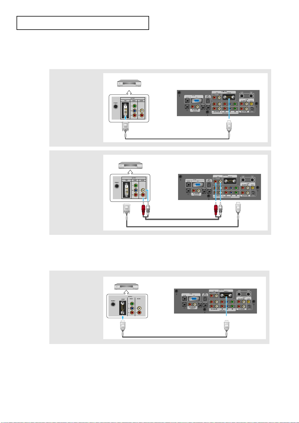
Connecting a DVD Player/Set-Top Box via DVI
This can be applied only if there is a DVI Output connector on the external device.
* Each external input source device has a different back panel configuration.
1
Connect a DVI to HDMI
cable or DVI-HDMI
Adapter between the
HDMI/DVI connector on
the TV and the DVI
connector on the DVD
player/Set-Top Box.
2
Connect an audio
cable between the
DVI IN [R-AUDIO-L
]
jack on the TV and the
AUDIO OUT
jacks on the DVD
player/Set-Top Box.
DVI to HDMI Cable (Option)
Audio Cable (Option)
DVD Player / Set-Top Box
TV Rear Panel
DVI to HDMI Cable (Option)
DVD Player / Set-Top Box
TV Rear Panel
Connecting a DVD Player/Set-Top Box via HDMI
This can be applied only if there is the HDMI Output connector on the external device.
1
Connect an HDMI
cable between the
HDMI/DVI connector
on the TV and the
HDMI connector on
the DVD player/
Set-Top Box.
What is HDMI?
•
HDMI, or high-definition multimedia interface, is a next-generation interface that enables the transmission
of digital audio and video signals using a single cable without compression.
•
“Multimedia interface” is a more accurate name for it especially because it allows multiple channels of
digital audio (5.1 channels). The difference between HDMI and DVI is that the HDMI device is smaller in
size, has the HDCP (High Bandwidth Digital Copy Protection) coding feature installed, and supports
multi-channel digital audio.
HDMI Cable (Option)
DVD Player Rear Panel
TV Rear Panel
CONNECTIONS
* When connecting an external device, match the color of the connection terminal to the cable.
English-17
CONNECTIONS
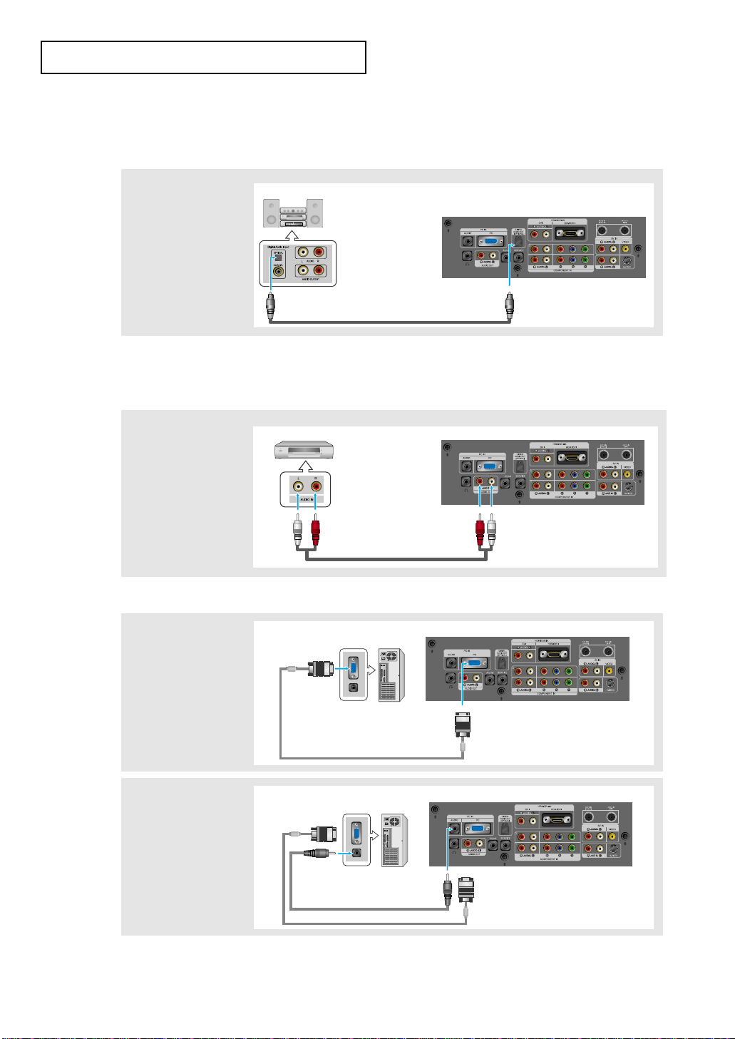
Connecting a PC
TV Rear Panel
D-Sub cable (Option)
PC
1
Connect a D-Sub
cable between PC IN
[PC] connector on the
TV and the PC output
connector on your
computer.
PC Audio Cable (Option)
TV Rear Panel
D-Sub cable (Option)
PC
2
Connect a PC audio
cable between PC IN
[AUDIO] jack on the
TV and the Audio Out
jack of the sound card
on your computer.
Connecting an Amplifier/DVD Home Theater
1
Connect an audio
cable between the
AUDIO OUT
[R-AUDIO-L] on the
TV and AUDIO IN
[R-AUDIO-L] on the
Amplifier/DVD Home
Theater.
Audio Cable (Option)
Amplifier/DVD Home Theater
TV Rear Panel
Note: 5.1CH broadcasting is possible when it is connected to an external device supporting 5.1CH.
For an explanation of Component video, see your Digital Audio System owner's manual.
Connecting a Digital Audio System
The rear panel jacks on your TV make it easy to connect a Digital Audio System to your TV.
1
Connect an optical
cable between the
DIGITAL AUDIO OUT
(OPTICAL) jacks on
the TV and the Digital
Audio Input jacks on
the Digital Audio
System.
Digital Audio System
TV Rear Panel
Optical Cable (Option)
* Each external input source device has a different back panel configuration.
* When connecting an external device, match the color of the connection terminal to the cable.
English-18
CONNECTIONS
Connecting CableCARD
(LN-R409D, LN40M51BD, LN-R469D, LN46M51BD)
You must obtain a CableCARD from a local cable service provider.
TV Rear Panel
1
Insert the CableCARD into the “CableCARD” slot and the message “CableCARD Inserted” is
displayed on the screen. If the channel information does not exist, the message “Updating
Channel List” is displayed during channel information configuration.
It could take several minutes to update the channel information depending on your cable
service provider.
2
The pairing information containing a telephone number, CableCARD ID, Host ID, and other
information will be displayed in about 2~3 minutes. If an error message is displayed, please
contact your service provider.
3
When the channel information configuration has finished, the message “Updating
Completed” is displayed, indicating that the channel list is now updated.
4
The Channel list can now be displayed by pressing the CH.LIST button.
RF Cable
CableCARD
Note
• Once the channel list has been updated, only the channels on the channel list can be selected.
• Remove the cable card by carefully pulling it out with your hands since dropping the cable card may
cause damage to it.

English-19
Chapter 3
OPERATION
Changing Channels
Using the Channel Buttons
1
Press the CH
/
buttons to change channels.
When you press the CH
/
buttons, the TV changes channels in sequence.
You will see all the channels that the TV has memorized. (The TV must have
memorized at least three channels). You will not see channels that were either
erased or not memorized. See pages 21-28 to memorize channels.
Using the PRE-CH Button to select the Previous Channel
1
Press the PRE-CH button.
The TV will switch to the last channel viewed.
To quickly switch between two channels that are far apart, tune to one channel,
then use the number button to select the second channel. Then use the PRE-CH
button to quickly alternate between them.
Adjusting the Volume
1
Press the VOL +/– buttons to increase or decrease the volume.
1
Press MUTE and the sound cuts off.
The word
“”
will appear in
the lower-left corner of the screen.
2
To turn mute off, press the MUTE button again, or simply press the VOL +/- buttons.
Using Mute
At any time, you can cut off the sound using the MUTE button.
Turning the TV On and Off
1
Press the POWER button
on the remote.
You can also use the POWER
button on the front of the panel.
English-20
Viewing the Display
The display identifies the current channel and the status
of certain audio-video settings.
Viewing the Menus
The screen displays
disappear after about ten seconds.
Press the INFO button once more
or wait approximately 10 seconds
and it disappears automatically.
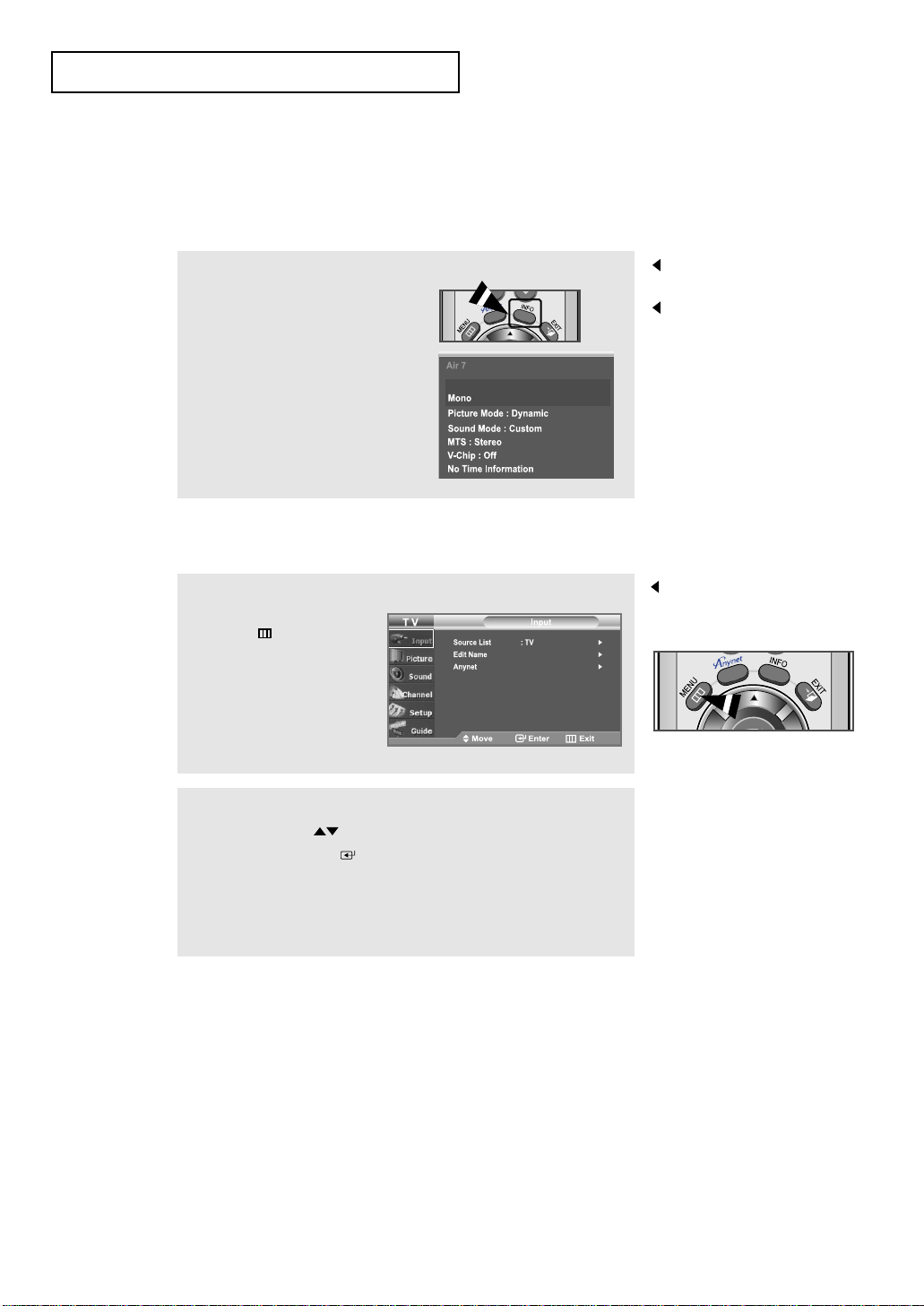
1
Press the INFO button on the
remote control.
The TV will display the
channel, the type of sound,
and the status of certain
picture and sound settings.
1
With the power on, press
the MENU button.
The main menu appears
on the screen. Its left
side has six icons:
Input, Picture, Sound,
Channel, Setup, Guide.
The on-screen menus
disappear from the screen after
about two minutes.
2
Use the UP/DOWN buttons to select one of the six icons.
Then press the ENTER button to access the icon’s
sub-menu.
3
Press the EXIT button to exit.
OPERATION
English-21
OPERATION
Plug & Play Feature
When the TV is initially powered on, two basic customer settings proceed
automatically and subsequently:
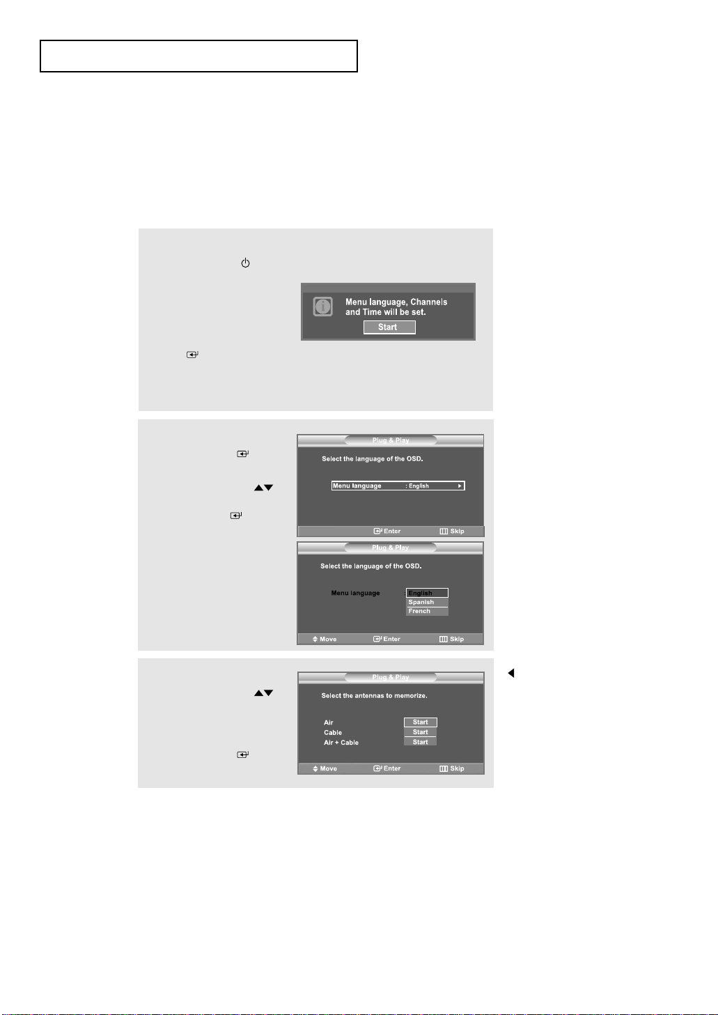
1
Press the POWER button
on the remote control.
The message
“Menu language, Channels
and
Time will be set.”
is displayed
. Press the
ENTER button, then
“Select the language of the
OSD” menu is automatically
displayed.
2
Press the ENTER button
to enter the language.
Press the
UP/DOWN
buttons to select language,
then the ENTER button.
“Select the antennas to
memorize.” menu is
automatically displayed.
3
Press the UP/DOWN
buttons to memorize the
channels of the selected
connection.
Press the
ENTER button
to select “Start”.
• If the antenna is connected
to ANT 1(CABLE),
select “CABLE” and if it is
connected to ANT 2
(AIR), select “AIR”.
• If both ANT 1 and ANT 2
are connected, select
the “Air + Cable”.
• If the CableCARD is
inserted into the
“CableCARD” slot on the
rear panel, “Cable” and
“Air+Cable” are not
available.
Some OSD can be different depending on the model.
English-22
OPERATION
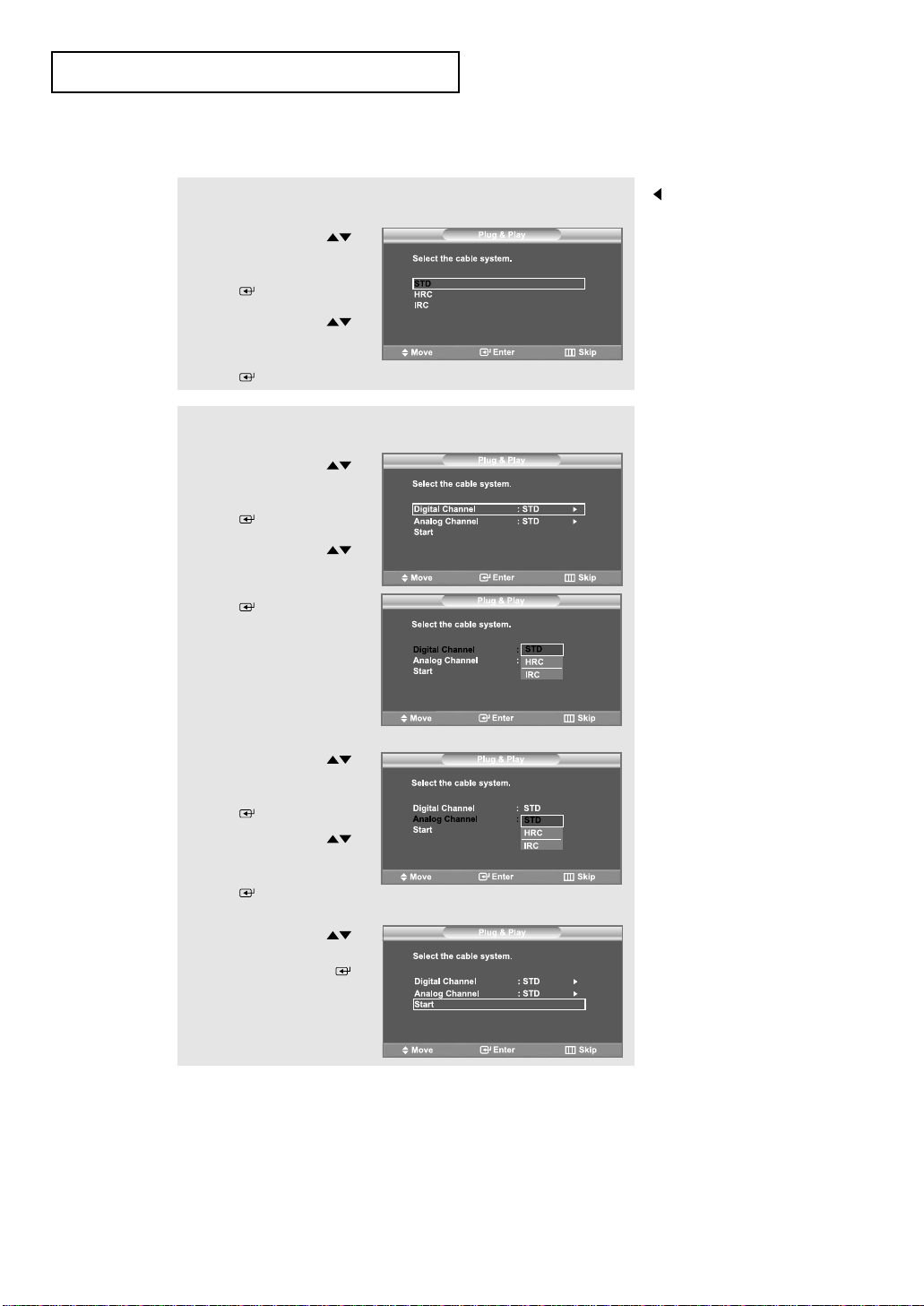
4-1
Press the UP/DOWN
buttons to select “Cable” or
“Air+Cable” then press the
ENTER button.
Press the
UP/DOWN
buttons to select “STD”,
“HRC” or “IRC”, press the
ENTER button.
STD, HRC and IRC
identify various types of
cable TV systems.
Contact your local cable
company to identify the
type of cable system that
exists in your particular
area.
At this point the signal
source has been selected.
Proceed to “Storing
Channels in Memory”.
(LN-R269D / LN-R329D / LN32M51BD)
4-2
Press the UP/DOWN
buttons to select “Digital
Channel”, then press the
ENTER button.
Press the
UP/DOWN
buttons to select “STD”,
“HRC” or “IRC”, press the
ENTER button.
Press the UP/DOWN
buttons to select “Analog
Channel”, then press the
ENTER button.
Press the
UP/DOWN
buttons to select “STD”,
“HRC” or “IRC”, press the
ENTER button.
Press the UP/DOWN
buttons to select “Start”,
then press the ENTER
button to memorize the
channels.
(LN-R409D / LN40M51BD / LN-R469D / LN46M51BD)
English-23
OPERATION
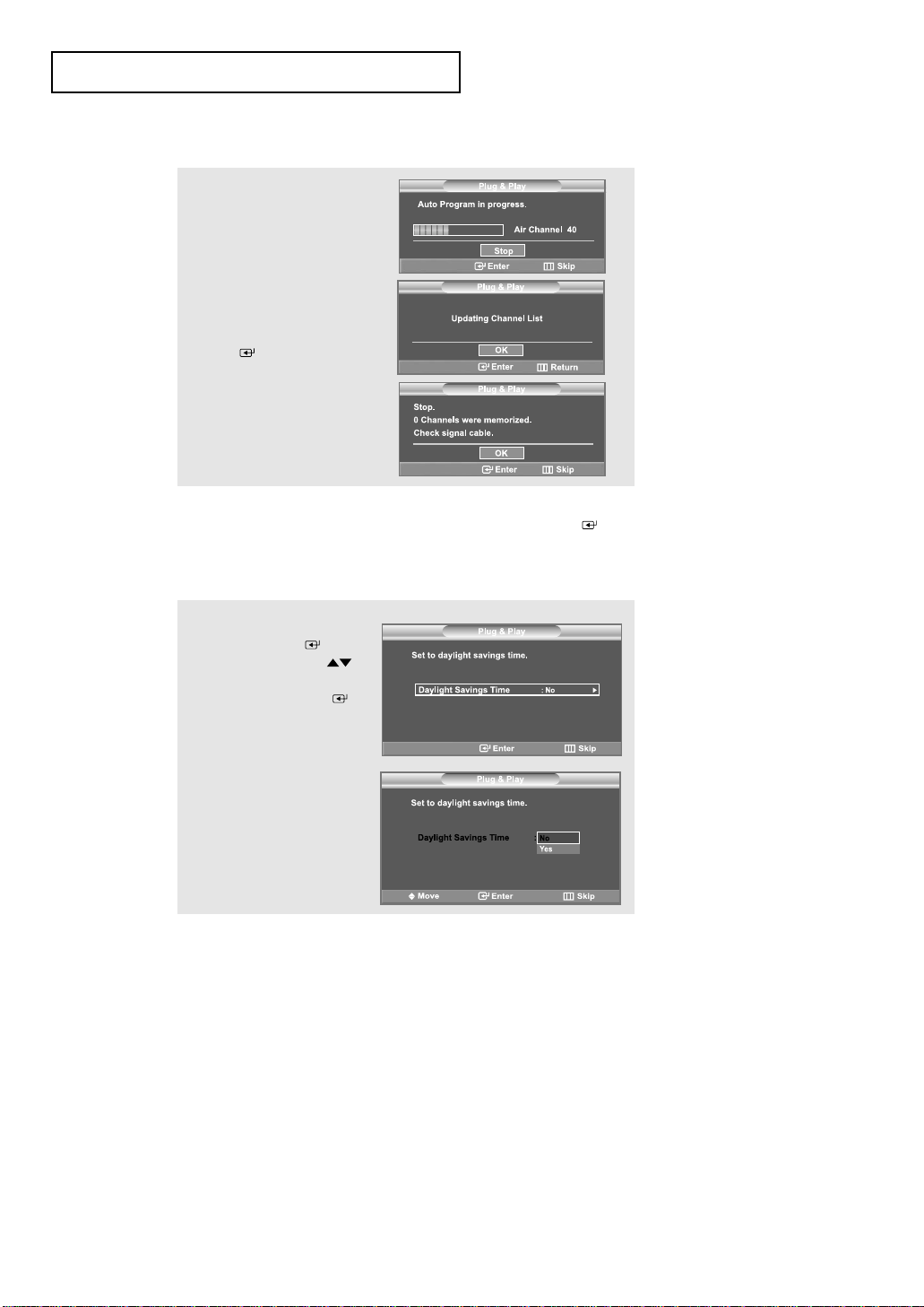
5
The TV will begin
memorizing all of the
available channels.
After all the available
channels are stored, the
Auto program menu
reappears. Press the
ENTER button when
channel memorization is
complete. “Set to daylight
savings time.” menu is
automatically displayed.
6
Press the ENTER button.
Press the UP/DOWN
buttons to select “Yes” or
“No”, then the ENTER
button. “Select your time
zone in which you live”
menu is automatically
displayed.
Note
• To stop the search before it has finished, press the
ENTER button with stop selected.
English-24
OPERATION
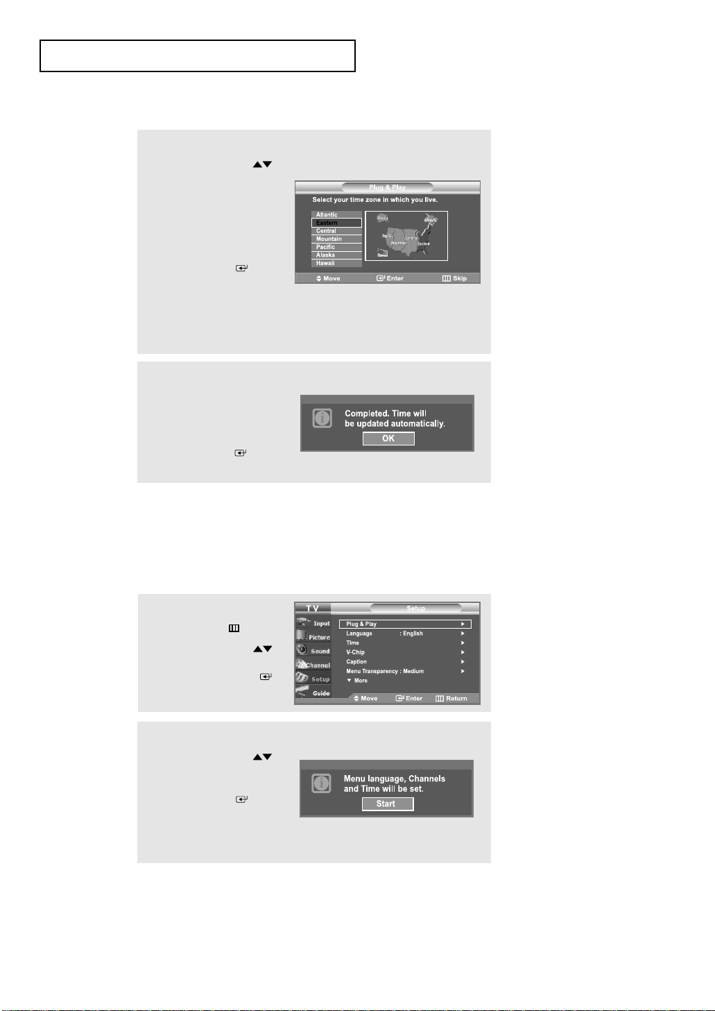
If you want to reset this feature...
1
Press the
MENU
button.
Press the UP/DOWN
buttons to select “Setup”,
then press the ENTER
button.
2
Press the UP/DOWN
buttons to select
“Plug & Play”.
Press the
ENTER button.
For further details on setting
up options, refer to the
previous page.
Note
• Plug and Play can only be accessed in the TV mode.
7
Press the UP/DOWN
buttons to highlight the time
zone for your local area
(and to move the highlight
to the appropriate time
zone on the map of the
United States).
Press the
ENTER
button. If you have received
a digital signal, the time will
be set automatically.
If not, see page 76 to set
the clock.
8
The message “Completed.
Time will be updated
automatically.” is displayed.
When you have finished,
press the
ENTER
button.
 Loading...