

Page 1
English-1
1-800-SAMSUNG (7267864)
Samsung Electronics America, Inc.
105 Challenger Road Ridgefield Park, NJ 07660-0511
Samsung Electronics Canada Inc., Customer Service
55 Standish Court Mississauga, Ontario L5R 4B2
Call center hours of operation (Mon-Sun 9AM-12AM EST).
To register this product please visit
www.samsung.com/global/register.
LN32A620A1F/LN40A620A1F
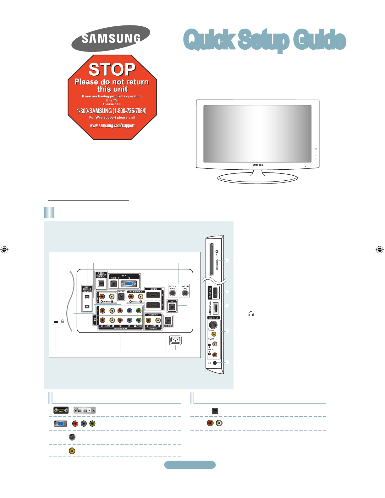
Rear Panel / Side Panel Jacks
1 2 3 4 5 6
@#$%&
7
5
9
0
8
^
!
1 D-NET (IEEE1394) S400MPEG
2 AUDIO OUT
3 DIGITAL AUDIO OUT (OPTICAL)
4 PC IN [PC] / [AUDIO]
5 HDMI IN 1, 2, 3 /
DVI IN(HDMI2)[R-AUDIO-L]
6 ANT 1 IN (CABLE) / ANT 2 IN (AIR)
7 CABLECARD™
8 WISELINK
9 AV IN 2 / S-VIDEO
0 HEADPHONE
! RJP
@ POWER INPUT
# VOL-CTRL
$ AUDIO OUT [R-AUDIO-L] /
VARIABLE [R-AUDIO-L]
% COMPONENT IN 1, 2 / AV IN 1
^ EX-LINK
& KENSINGTON LOCK
Audio Output Performance Comparison
OPTICAL (Digital)
AUDIO (Analog)
Best
Normal
Video Input Performance Comparison
HDMI/DVI
PC/COMPONENT
S-VIDEO
VIDEO
Best
Better
Good
Normal
/
/
Quick Setup Guide
Page 2
English-2
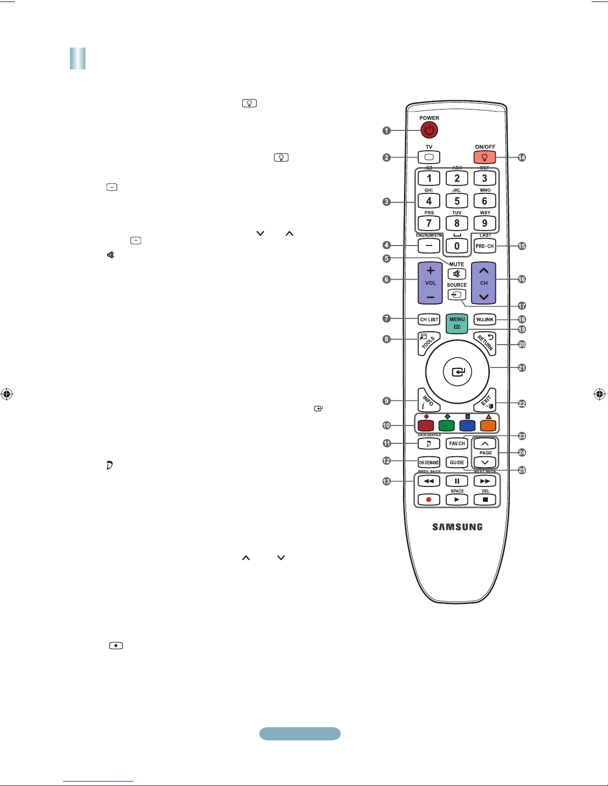
Remote Control
See “Remote Control” in the owner’s instructions for details.
1
POWER
Turns the TV on and off.
2
TV
Selects the TV mode directly.
3
NUMERIC BUTTONS
Press to directly select the
channel.
4
Press to select additional
channels (digital and analog)
being broadcast by the same
station. For example, to select
channel “54-3”, press “54”, then
press “ ” and “3”.
5
(MUTE)
Press to temporarily cut off the
sound.
6
VOL – / VOL +
Press to increase or decrease
the volume.
7
CH LIST
Used to display Channel Lists
on the screen.
8
TOOLS
Use to quickly select frequently
used functions.
9
INFO
Press to display information on
the TV screen.
0
COLOR BUTTONS
Use these buttons in the
Channel list, WISELINK, menus
etc.
!
BUTTON
Press to display the Data
Application list. You can run an
application by selecting from
the list.
@
ON-DEMAND
Press to display the MOD
(Movie on Demand) menu when
the feature is available.
(MOD is a new type of video
service that provides movies
over the cable TV network.
Subscribers can choose movies,
and then control playback,
search the index, as well as
send queries.)
#
Use these buttons in the
DMA, WISELINK and Anynet+
modes.
( : This remote can be
used to control recording on
Samsung recorders with the
Anynet+ feature)
$
ON/OFF
Press to backlight the buttons
on the remote. This function is
convenient for using at night or
when the room is dark. (Using
the remote control with the
ON/OFF light button set to
On will reduce the battery usage
time.)
%
PRE-CH
Enables you to return to the
previous channel you were
watching.
^
CH / CH
Press to change channels.
&
SOURCE
Press to display and select the
available video sources.
*
W.LINK (WISELINK)
This function enables you to
view and play photo and music
files from an external device.
(
MENU
Displays the main on-screen
menu.
)
RETURN
Returns to the previous menu.
a
UP▲/DOWN▼/LEFT◄ /
RIGHT►/ENTER
Press the Up/Down/Left/Right
sections of the wheel button and
Enter to select on-screen menu
items and change menu values.
You can navigate up and down
the menu, switch channels and
adjust the volume by turning the
wheel button.
b
EXIT
Press to exit the menu.
c
FAV.CH
Press to switch to your favorite
channels.
d
PAGE
Use to scroll the screen or text in
the Data Application downloaded.
e
GUIDE
Press to display the TV Guide
menu when the guide is provided
from the downloaded application.
When no TV Guide is available
in the downloaded application,
the EPG is not displayed and the
“No Available Banner” message
appears.
Page 3
English-3
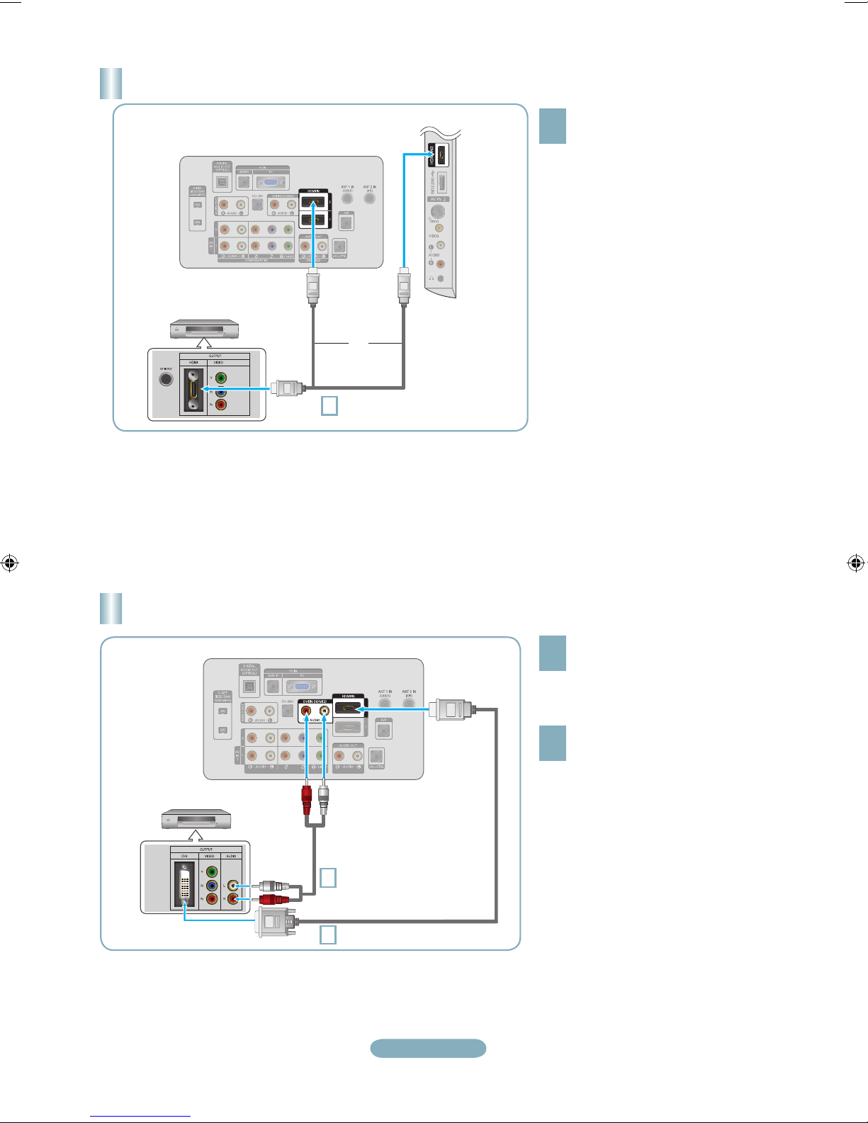
Connecting a DVD/Blu-Ray player/Satellite receiver (Set-Top Box) via DVI
TV Rear Panel
1
DVI to HDMI Cable (Not supplied)
2
Audio Cable (Not supplied)
1
Connect a DVI to HDMI Cable or
DVI-HDMI Adapter between the HDMI
IN 2 jack on the TV and the DVI jack
on the DVD/Blu-Ray player/Satellite
receiver (Set-Top Box).
2
Connect Audio Cables between the
DVI IN (HDMI 2) [R-AUDIO-L] jack on
the TV and the DVD/Blu-Ray player/
Satellite receiver (Set-Top Box).
Connecting a DVD/Blu-Ray player/Satellite receiver (Set-Top Box) via HDMI
1
What is HDMI?
•
HDMI(High-Definition Multimedia
Interface), is an interface that enables the
transmission of digital audio and video
signals using a single cable.
•
The difference between HDMI and DVI
is that the HDMI device is smaller in
size and has the HDCP (High Bandwidth
Digital Copy Protection) coding feature
installed.
Connect an HDMI Cable between
the HDMI IN (1, 2 or 3) jack on
the TV and the HDMI jack on
the DVD/Blu-Ray player/Satellite
receiver (Set-Top Box).
DVD/Blu-Ray player/
Satellite receiver (Set-Top Box)
Each DVD/Blu-Ray player/Satellite receiver (Set-Top Box) has a different back panel configuration.
When connecting a DVD/Blu-Ray player/Satellite receiver (Set-Top Box), match the color of the connection terminal to the cable.
When using an HDMI/DVI cable connection, you must use the HDMI IN 2 jack.
➣
➣
➣
TV Rear Panel
TV Side Panel
HDMI Cable (Not supplied)
1
or
Each DVD/Blu-Ray player/Satellite receiver (Set-Top Box) has a different back panel configuration.
The TV may not output sound and pictures may be displayed with abnormal color when DVD players/Satellite receivers
supporting HDMI versions older than 1.3 are connected. When connecting an older HDMI cable and there is no sound, connect
the HDMI cable to the HDMI IN 2 jack and the audio cables to the DVI IN (HDMI2) [R-AUDIO-L] jacks on the back of the TV. If
this happens, contact the company that provided the DVD player/Satellite receiver to confirm the HDMI version, then request an
upgrade.
HDMI cables that are not 1.3 may cause annoying flicker or no screen display.
➣
➣
➣
DVD/Blu-Ray player/
Satellite receiver
(Set-Top Box) Rear Panel
Page 4

English-4
Connecting a DVD/Blu-Ray player/Satellite receiver (Set-Top Box) via
Component cables
TV Rear Panel
1
Component Cable
(Not supplied)
DVD/Blu-Ray player/
Satellite receiver (Set-Top Box)
2
Audio Cable (Not supplied)
1
Connect a Component Cable between
the COMPONENT IN (1 or 2)
[Y, PB, PR] jacks on the TV and the
COMPONENT [Y, PB, PR] jacks on the
DVD/Blu-Ray player/Satellite receiver
(Set-Top Box).
2
Connect Audio Cables between the
COMPONENT IN(1 or 2) [R-AUDIO-L]
jacks on the TV and the AUDIO OUT
jacks on the DVD/Blu-Ray player/
Satellite receiver (Set-Top Box).
Component video separates the video
into Y (Luminance (brightness)), Pb
(Blue) and Pr (Red) for enhanced video
quality. Be sure to match the component
video and audio connections.
For example, if connecting a Component
video cable to COMPONENT IN 1,
connect the audio cable to
COMPONENT IN 1 also.
Each DVD/Blu-Ray player/Satellite
receiver (Set-Top Box) has a different
back panel configuration.
When connecting a DVD/Blu-Ray player/
Satellite receiver (Set-Top Box), match
the color of the connection terminal to
the cable.
➣
➣
➣
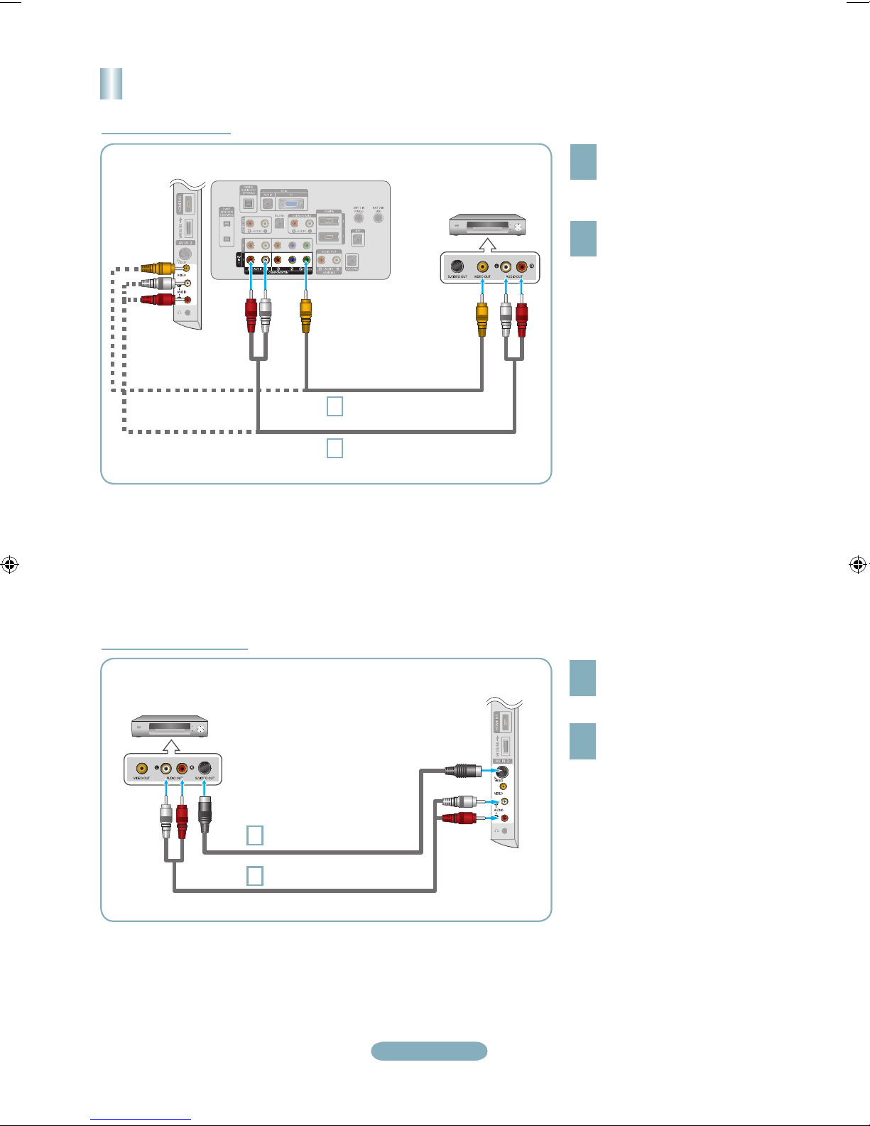
Connecting a Camcorder
1
Connect a Video Cable (or S-Video
Cable) between the AV IN2 [VIDEO]
(or S-VIDEO) jack on the TV and the
VIDEO OUT jack on the camcorder.
2
Connect Audio Cables between the
AV IN2 [R-AUDIO-L] jacks on the TV
and the AUDIO OUT jacks on the
camcorder.
Each Camcorder has a different back
panel configuration.
When connecting a Camcorder, match
the color of the connection terminal to
the cable.
➣
➣
or
2
Camcoder
1
1
TV Side Panel
Audio cable
(Not supplied)
S-Video cable (Not supplied)
Audio cable (Not supplied)
Page 5
English-5
Connecting a VCR
1
If you have a “mono” (non-stereo) VCR,
use a Y-connector (not supplied) to
connect to the right and left audio input
jacks of the TV. Alternatively, connect
the cable to the “R” jack. If your VCR is
stereo, you must connect two cables.
➣
Follow the instructions in “Viewing a VCR or Camcorder Tape” to view your VCR tape.
Each VCR has a different back panel configuration.
When connecting a VCR, match the color of the connection terminal to the cable.
When connecting to AV NI 1, the color of the AV IN 1 [Y/VIDEO] jack (Green) does not match the color of the video cable
(Yellow).
➣
➣
➣
TV Rear Panel
1
Video Cable (Not supplied)
VCR Rear Panel
2
Audio Cable (Not supplied)
2
Connect a Video Cable
between the VIDEO OUT jack
on the VCR and the AV IN 1
[Y/VIDEO] or AV IN 2 [VIDEO]
jack on the TV.
Connect Audio Cables between
the AUDIO OUT jacks on the
VCR and the AV IN 1 (or AV IN 2)
[R-AUDIO-L] jacks on the TV.
Video Connection
S-Video Connection
2
Audio Cable (Not supplied)
VCR Rear Panel
1
Connect an S-Video Cable
between the S-VIDEO OUT jack
on the VCR and the AV IN 2
[S-VIDEO] jack on the TV.
2
Connect Audio Cables between
the AUDIO OUT jacks on the VCR
and the AV IN 2 [R-AUDIO-L]
jacks on the TV.
An S-Video cable may be included
with a VCR. (If not, check your local
electronics store.)
Each VCR has a different back
panel configuration.
When connecting a VCR, match
the color of the connection
terminal to the cable.
➣
➣
1
S-Video Cable (Not supplied)
TV Side Panel
TV Side Panel
Page 6
English-6
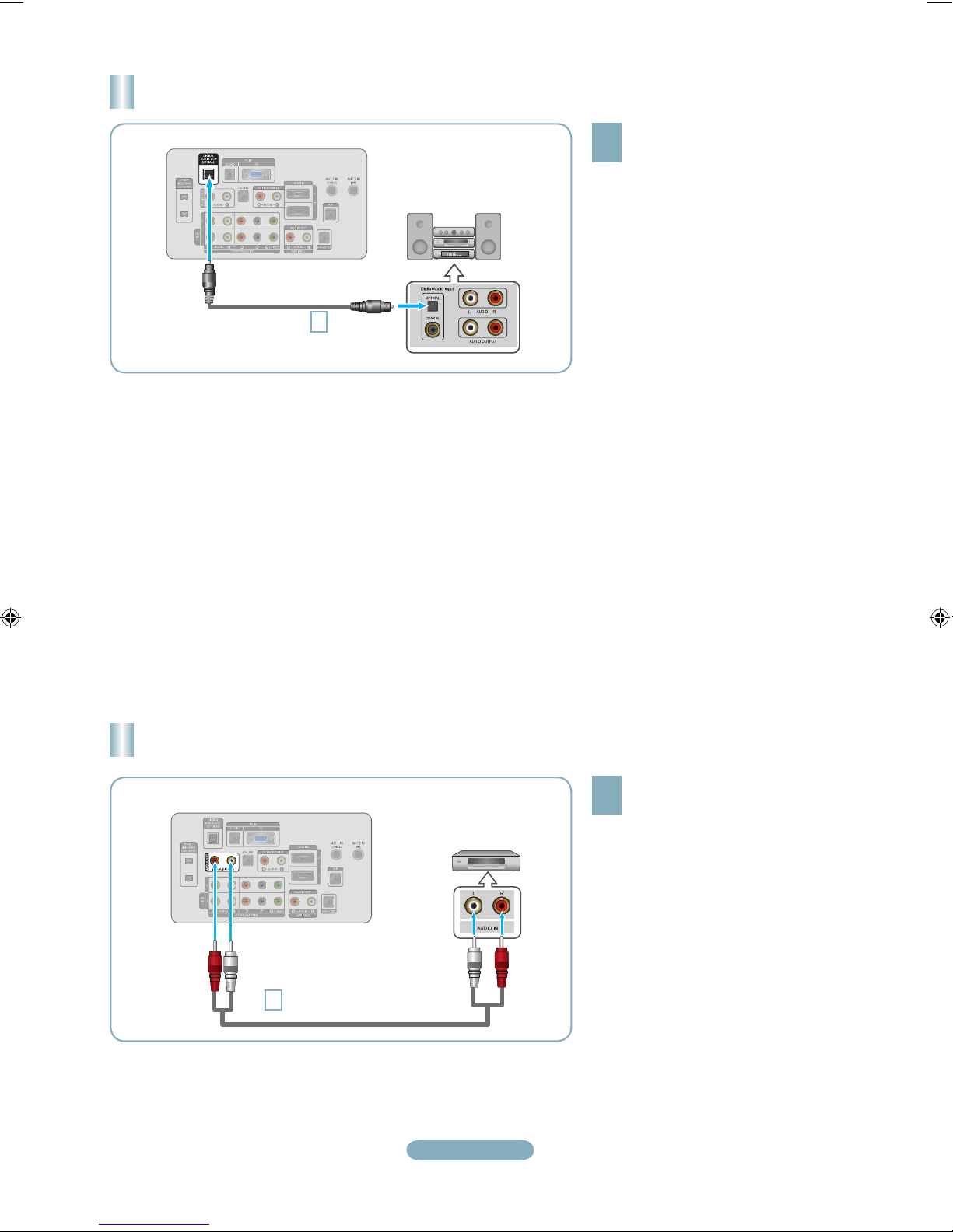
Connecting a Digital Audio System
TV Rear Panel
1
Optical Cable
(Not supplied)
Digital Audio System
1
Connect an Optical Cable between
the “DIGITAL AUDIO OUT
(OPTICAL)” jacks on the TV and
the Digital Audio Input jacks on the
Digital Audio System.
When a Digital Audio System is
connected to the “DIGITAL AUDIO
OUT (OPTICAL)” jack: Decrease
the volume of the TV and adjust
the volume level with the system’s
volume control.
5.1CH audio is possible when the TV
is connected to an external device
supporting 5.1CH.
Each Digital Audio System has a
different back panel configuration.
When the receiver (home theater) is
set to On, you can hear sound output
from the TV’s Optical jack. When the
TV is displaying a DTV(air) signal, the
TV will send out 5.1 channel sound to
the Home theater receiver. When the
source is a digital component such as
a DVD and is connected to the TV via
HDMI, only 2 channel sound will be
heard from the Home Theater receiver.
If you want to hear 5.1 channel audio,
connect the DIGITAL AUDIO OUT
(OPTICAL) jack on the DVD player
or Cable/Satellite Box directly to an
Amplifier or Home Theater, not the TV.
➣
➣
➣
Connecting an Amplifier/DVD Home Theater
TV Rear Panel
1
Audio Cable (Not supplied)
Amplifier/DVD Home Theater
1
Connect Audio Cables between the
AUDIO OUT [R-AUDIO-L] jacks on
the TV and AUDIO IN [R-AUDIO-L]
jacks on the Amplifier/DVD Home
Theater.
When an audio amplifier is connected
to the “AUDIO OUT [R-AUDIO-L]”
jack: Decrease the volume of the TV
and adjust the volume level with the
Amplifier’s volume control.
Each Amplifier/DVD Home Theater has
a different back panel configuration.
When connecting an Amplifier/DVD
Home Theater, match the color of the
connection terminal to the cable.
➣
➣
Page 7
English-7
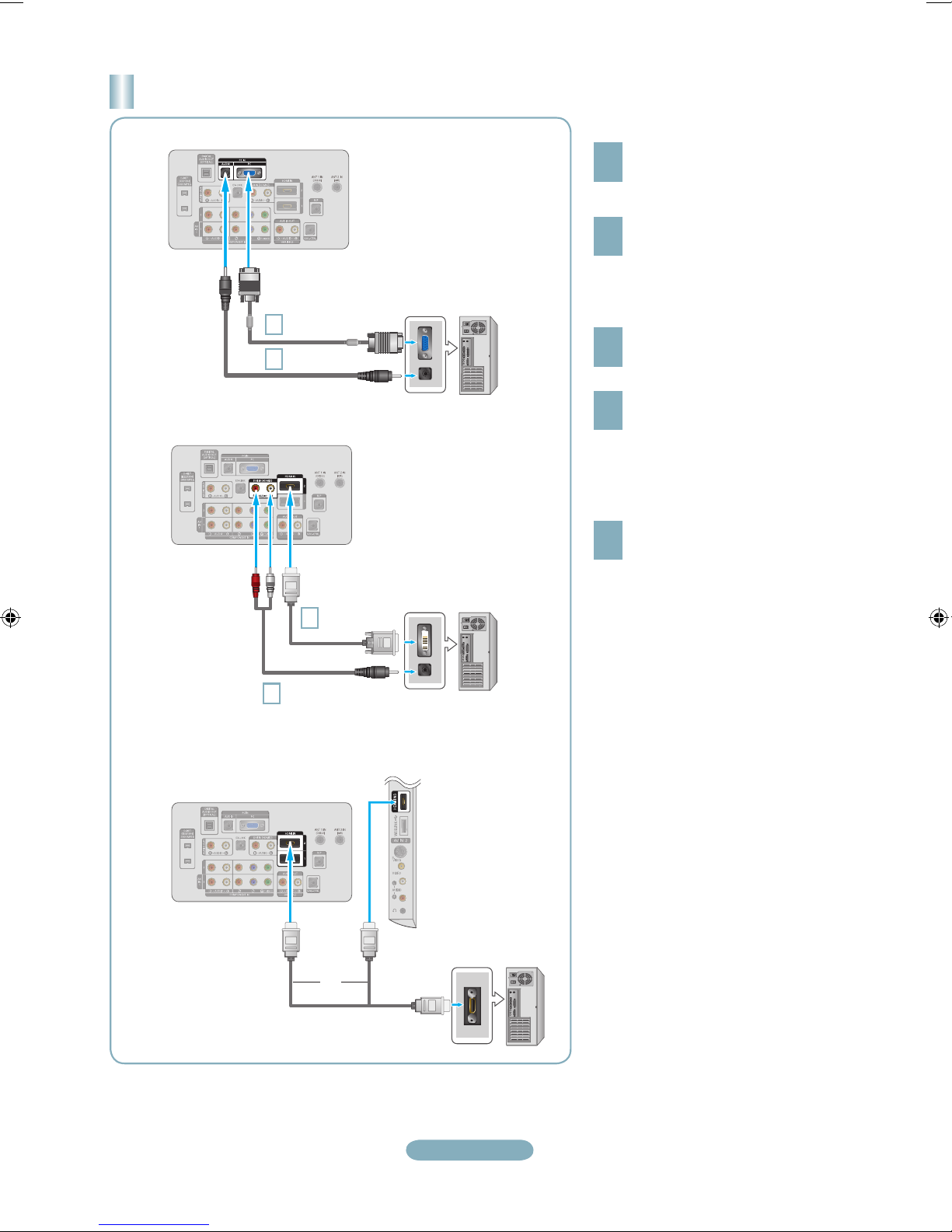
Connecting a PC
TV Rear Panel
1
D-Sub Cable
(Not supplied)
PC
2
PC Audio Cable
(Not supplied)
1
Connect a D-Sub Cable between
PC IN [PC] connector on the TV and
the PC output connector on your
computer.
2
Connect a PC Audio Cable between
the PC IN [AUDIO] jack on the TV
and the Audio Out jack of the sound
card on your computer.
Each PC has a different back panel
configuration.
When connecting a PC, match the
color of the connection terminal to the
cable.
When using an HDMI/DVI cable
connection, you must use the HDMI
IN 2 terminal.
➣
➣
➣
Using the D-Sub Cable
1
Connect an HDMI/DVI cable between
the HDMI IN 2 jack on the TV and
the PC output jack on your computer.
2
Connect a 3.5 mm Stereo miniplug/2RCA Cable between the DVI
IN(HDMI2) [R-AUDIO-L] jack on the
TV and the Audio Out jack of the
sound card on your computer.
Using the HDMI/DVI Cable
Using the D-Sub Cable
TV Rear Panel
PC
1
HDMI/DVI Cable
(Not supplied)
2
3.5 mm Stereo mini-plug/
2RCA Cable (Not supplied)
Using the HDMI/DVI Cable
TV Rear Panel
Using the HDMI Cable
TV Side Panel
HDMI Cable (Not supplied)
PC
or
1
Connect an HDMI cable between
the HDMI IN(1, 2 or 3) jack on the
TV and the PC output jack on your
computer.
Using the HDMI Cable
Page 8
English-8
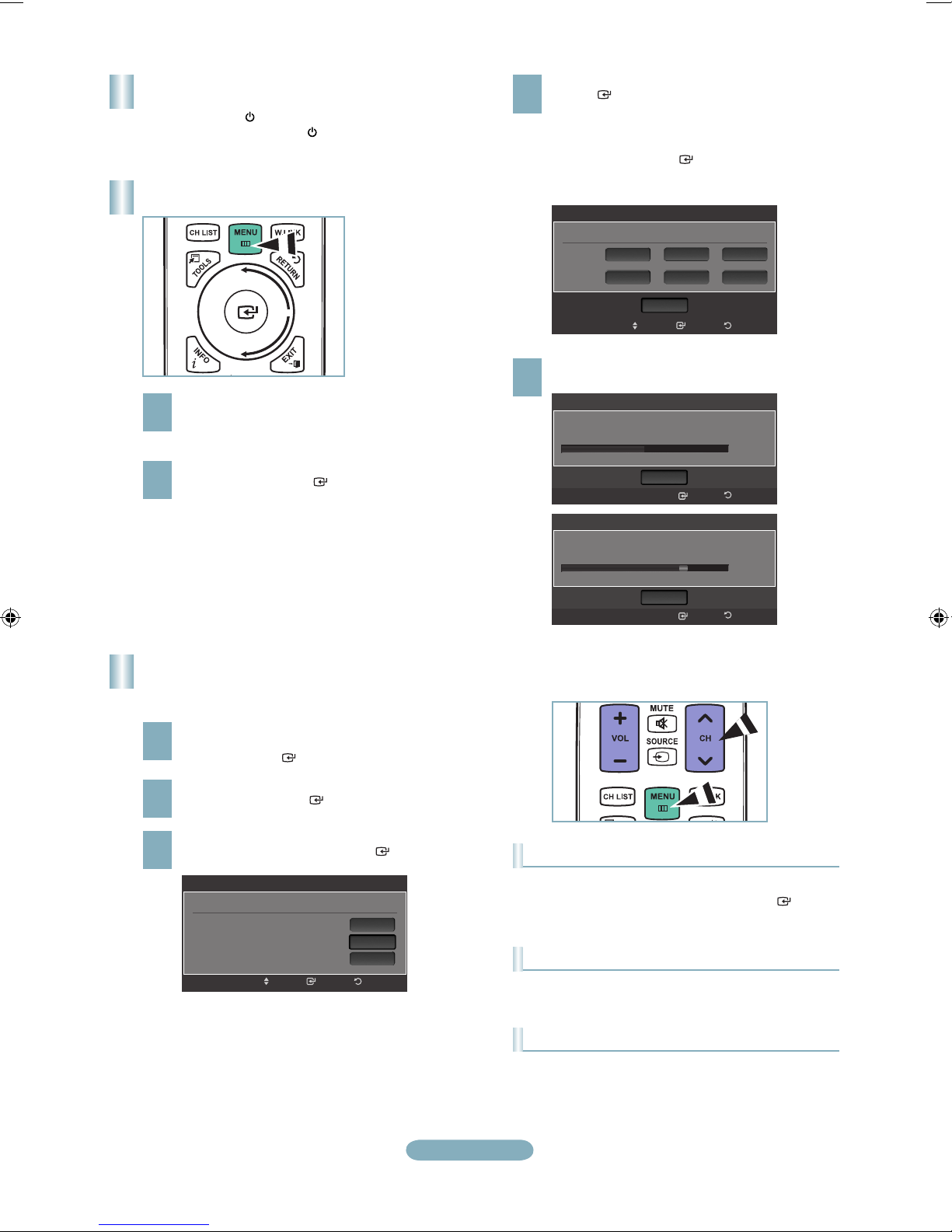
Turning the TV On and Off
Press the POWER button on the remote control.
You can also use the POWER button on the TV.
1
2
With the power on, press the MENU button.
The main menu appears on the screen.
The menu’s left side has icons: Picture, Sound,
Channel, Setup, Input, Application.
Press the ▲ or ▼ button to select one of the icons.
Then press the ENTER
button to access the
icon’s sub-menu. Press the EXIT button to exit.
To move to a lower menu, turn the wheel
clockwise when the menu Display is displayed.
To move to a higher menu, turn the wheel
counterclockwise.
The on-screen menus disappear from the
screen after about one minute.
➣
➣
Storing Channels in Memory
(Automatic Method)
1
Press the MENU button to display the menu.
Press the ▲ or ▼ button to select “Channel”, then
press the ENTER button.
2
Press the ▲ or ▼ button to select “Auto Program”,
then press the ENTER button.
3
Press the ▲ or ▼ button to select the antenna
connection, then press the ENTER button.
4
When selecting the Cable TV system: Press the
ENTER
button to start the auto program.
Press the ▲,▼, ◄ or ► to select the correct analog
signal cable system source among “STD”, “HRC”,
and “IRC”. Press the ▲ or ▼ button to select “Start”,
then press the ENTER
button. If you have Digital
cable TV, select the cable system signal source for
both Analog and Digital.
Viewing the Menus
5
The TV begins memorizing all available stations.
Press the EXIT button to exit.
To Stop the Auto Program Function
Press the MENU button while the Auto Program function is
being executed. You can also press the ENTER button
to stop the setup.
Checking to see if Channels were Stored in Memory
Press the CH button. Only the channels stored in memory
will be selected (in order).
Selecting the antennas
• Air: “Air” antenna signal.
• Cable: “Cable” antenna signal.
• Air+Cable: “Air” and “Cable” antenna signals.
Auto Program
Auto Program in Progress.
Stop
Enter
Cable 38
50%
Return
DTV Cable : 12 Cable : 32
Auto Program
Removing scrambled channel.
Stop
Enter
DTV Cable 41
77%
Return
DTV Cable : 16 Cable : 45
After all the available channels are stored, it
starts to remove scrambled channels. The Auto
program menu then reappears.
➣
ReturnEnter
Auto Program
Selects the cable system.
Analog
Digital
HRC IRC
HRC IRC
Move
STD
Start
STD
Auto Program
Select the Antenna source to memorize.
Air
Cable
Air+Cable
Start
Start
Start
ReturnEnterMove
Page 9
English-9
Mode : Standard
Backlight : 7
►
Contrast : 95
Brightness : 45
Sharpness : 50
Color : 50
Tint (G/R) : G50/R50
Detailed Settings
Picture
Option
Picture
7Backlight
Enter Return
AdjustMove
2 Air
4 Air
4-2 ♥ TV #8
8 Air
13 Air
13-1 ♥ TV #3 M. Spillane’s mike Hammer
All Channels
Air
Antenna Zoom Select
Option
Delete
Add to Favorite
Timer Viewing
Channel Name Edit
Select All
Auto Program
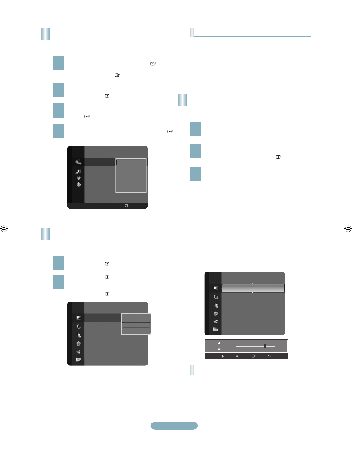
Setting the Channel List
You can delete or add a channel to display the channels
you want.
1
Press the MENU button. Press the ▲ or ▼ button to
select “Channel”, then press the ENTER button.
Press the ▲ or ▼ button to select “Channel List”,
then press the ENTER button.
2
Press the ◄ button to select “Added Channels”.
Press the ▲ or ▼ button to select “All Channels”.
Press the ENTER button.
3
Press the ▲ or ▼ button to select a channel to
delete, then press the TOOLS button. Press the
ENTER button to select “Delete”.
4
Press the ▲ or ▼ button to select a channel to add,
then press the TOOLS button. Press the ENTER
button to select “Add”.
Changing the Picture Standard
You can select the type of picture which best corresponds
to your viewing requirements.
1
Press the MENU button to display the menu.
Press the ENTER button, to select “Picture”.
2
Press the ENTER button to select “Mode”.
Press the ▲ or ▼ button to select “Dynamic”,
“Standard” or “Movie”.
Press the ENTER button.
Customizing the Picture Settings
Your television has several setting options that allow you to
control the picture quality.
1
To select the desired picture mode, follow the
“Changing the Picture Standard” instructions
numbers 1 and 2.
2
Press the ▲ or ▼ button to select “Backlight”,
“Contrast”, “Brightness”, “Sharpness”, “Color” or
“Tint(G/R)”, then press the ENTER button.
Picture Mode
• Dynamic: Selects the picture for high-definition in a bright
room.
• Standard: Selects the picture for the optimum display in a
normal environment.
• Movie: Selects the picture for viewing movies in a dark
room.
3
Press the ◄ or ► button to decrease or increase
the value of a particular item. Press the EXIT button
to exit.
When you make changes to “Backlight”,
“Contrast”, “Brightness”, “Sharpness”, “Color”
or “Tint(G/R)”, the OSD will be adjusted
accordingly.
In PC mode, you can only make changes to
“Backlight”, “Contrast” and “Brightness”.
Settings can be adjusted and stored for each
external device you have connected to an input
of the TV.
The energy consumed during use can be
significantly reduced if the level of brightness of
the picture is reduced, and that this will reduce
the overall running cost.
➣
➣
➣
➣
Picture Adjustment
• Backlight: Adjusts the brightness of LCD back light.
• Contrast: Adjusts the contrast level of the picture.
• Brightness: Adjusts the brightness level of the picture.
• Sharpness: Adjusts the edge definition of the picture.
• Color: Adjusts color saturation of the picture.
• Tint(G/R): Adjusts the color tint of the picture.
Picture
Mode
:
Standard
►
Backlight : 7
Contrast : 95
Brightness : 45
Sharpness : 50
Color : 50
Tint (G/R) : G50/R50
Detailed Settings
Dynamic
Standard
Movie
Page 10
English-10
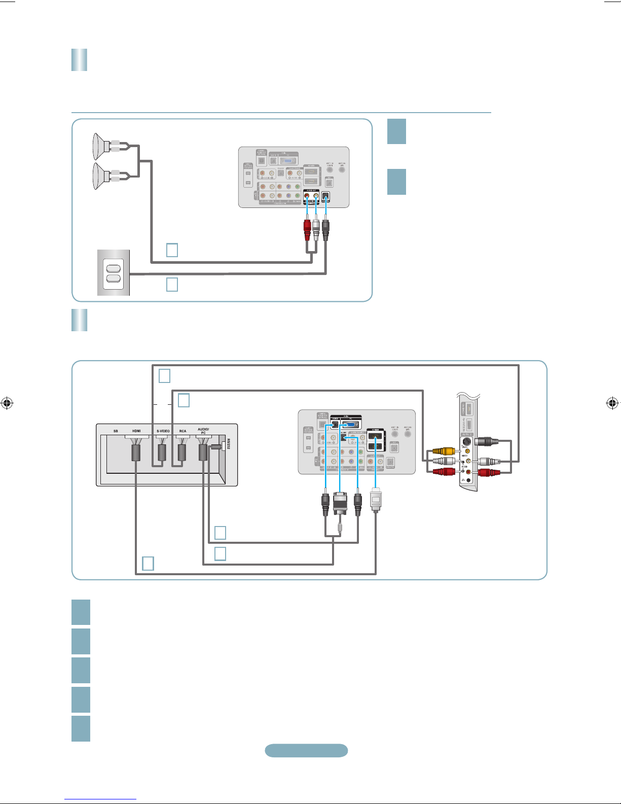
Connecting the Bathroom Speakers
VOL +
VOL
-
L
-
L +
R
-
R +
Connecting through the Variable Output (available without an external amplifier)
See 'Connecting the Bathroom Speakers' in the owner’s instructions for details.
This function is only available when the TV is installed in a hotel.
➣
➣
TV Rear Panel
1
Red : Right / White : Left
Speaker
Volume Control Box
2
1
Connect the VARIABLE AUDIO
[R-AUDIO-L] port of the TV to the
Bathroom Wall Speakers of the
hotel.
2
Connect the [VOL-CTRL] jack of
the TV to the Volume Control Box
Switch port of the Bathroom Wall of
the hotel.
Each VCR has a different back
panel configuration.
➣
TV Rear Panel
2
Video / Audio Cable
RJP Rear
3
S-Video / Audio Cable
5
1
D-sub / PC Audio cable
4
HDMI cable
TV Side Panel
or
1
Connect the PC IN [PC] / [AUDIO] port of the TV to the PC/AUDIO port of the RJP.
2
Connect the AV IN [VIDEO]/[R-AUDIO-L] port of the TV to the RCA port of the RJP.
3
Connect the S-VIDEO / AV IN[R-AUDIO-L] port of the TV to the S-VIDEO port of the RJP.
You cannot connect and use the AV and S-VIDEO ports at the same time.
➣
4
Connect the [HDMI] port of the TV and the HDMI port of the RJP.
5
Connect the EX-LINK port of the TV and the RS/232 port of the RJP.
The RJP (Remote Jack Pack) compatible with this Samsung TV is TeleAdapt TA-7610.
➣
Output of any external source connected to RJP on hotel desk.
Connecting the RJP(Remote Jack Pack)
See 'Connecting the RJP(Remote Jack Pack)' in the owner’s instructions for details.
➣
This function is only available when the TV is installed in a hotel.
➣
Page 11

English-11
Troubleshooting
If the TV seems to have a problem, first try this list of possible problems and solutions.
If none of these troubleshooting tips apply, call Samsung customer service at 1-800-SAMSUNG.
Problem Possible Solution
Poor picture Try another channel. / Adjust the antenna. / Check all wire connections.
Poor sound quality. Try another channel. / Adjust the antenna.
No picture or sound. Try another channel. / Press the SOURCE button. /
Make sure the TV is plugged in. / Check the antenna connections.
No sound or sound is too low at maximum
volume.
First, check the volume of units connected to your TV (digital broadcasting
receiver, DVD, cable broadcasting receiver, VCR, etc.). Then, adjust the TV
volume accordingly.
Picture rolls vertically. Check all wire connections.
There is a problem with the picture Run the Picture test in the Self diagnostic menu.
There is a problem with the sound Run the Sound test in the Self diagnostic menu.
The TV operates erratically. Unplug the TV for 30 seconds, then try operating it again.
The TV won’t turn on. Make sure the wall outlet is working.
Remote control malfunctions Replace the remote control batteries.
Clean the upper edge of the remote control (transmission window).
Check the battery terminals.
“Check signal cable” message. Ensure that the signal cable is rmly connected to the PC source.
“Not Supported Mode” message. Check the maximum resolution and connected device’s Video frequency.
Compare these values with the data in the Display Modes.
Digital broadcasting screen problem. Please check the digital signal strength and input antenna.
The image is too light or too dark. Adjust the Brightness and Contrast. / Adjust the Fine tuning.
Black bars on the screen. Make sure the broadcast you’re receiving is High Denition (HD).
HD channels sometimes broadcast Standard Denition (SD) programming, which
can cause black bars.
Set your cable/satellite box to stretch or widescreen mode to eliminate the bars.
Picture has a Red/Green or Pink tint. Make sure the Component cables are connected to the correct jacks.
Closed Captioning not working. If you are using a Cable/Satellite box, you must set Closed Captioning on the box,
not your TV.
Snowy picture. Your cable box may need a rmware upgrade. Please contact your Cable
company.
Ghosting on picture This is sometimes caused by compatibility issues with your cable box.
Try connecting Component cables instead.
Horizontal bars appear to icker, jitter or
shimmer on the image.
Adjust the Coarse tuning and then adjust the Fine tuning.
Vertical bars appear to icker, jitter or
shimmer on the image.
Adjust the Coarse tuning and then adjust the Fine tuning.
Screen is black and power indicator light
blinks steadily.
On your computer check: Power, Signal Cable.
The TV is using its power management system.
Move the computer's mouse or press any key on the keyboard.
Image is not centered on the screen. Adjust the horizontal and vertical position.
The screen position must be adjusted on the output source (i.e. STB) with a
digital signal.
The picture appears distorted in the
corner of the screen.
If "Just Scan" is selected with some external devices, the picture may appear
distorted in the corner of the screen. This symptom is caused by the external
devices, not TV.
The "Resets all settings to the default
values" message appears.
This appears when you press and hold the EXIT button for a while. The product
settings are reset to the factory defaults.
You may see small particles if you
look closely at the edge of the bezel
surrounding the TV screen.
This is part of the product's design and is not a defect.
Page 12
BN68-01801A-01
Contact SAMSUNG WORLDWIDE
If you have any questions or comments relating to Samsung products, please contact the SAMSUNG customer care center.
Contacte con SAMSUNG WORLDWIDE
Si tiene alguna pregunta o comentario referente a nuestros productos, por favor contacte con nuestro Servicio de Atención al
Cliente.
Country
Customer Care Center
Web Site Address
CANADA 1-800-SAMSUNG(726-7864) www.samsung.com/ca
Samsung Electronics Canada Inc., Customer
Service 55 Standish Court Mississauga,
Ontario L5R 4B2 Canada
Samsung Electronique Canada Inc.,
Service à la Clientèle 55 Standish Court
Mississauga, Ontario L5R 4B2 Canada
U.S.A 1-800-SAMSUNG(726-7864) www.samsung.com/us
Samsung Electronics America, Inc.
105 Challenger Road
Ridgefield Park, NJ 07660-0511
 Loading...