

Samsung LH015I SERIES, LH020I SERIES, LH025I SERIES Installation Manual
Samsung Electronics LED Display Installation
LED Display
Installation Manual
LH015I ***** (P1.5)
LH020I ***** (P2.0)
LH025I ***** (P2.5)
Ver. 2.1

Samsung Electronics LED Display Installation
Table of Contents
1. Specification
1-1 Product Concept
1-2 Specification
1-3 Dimension spec
1-4 Exploded View
1-5 Viewing the Connection
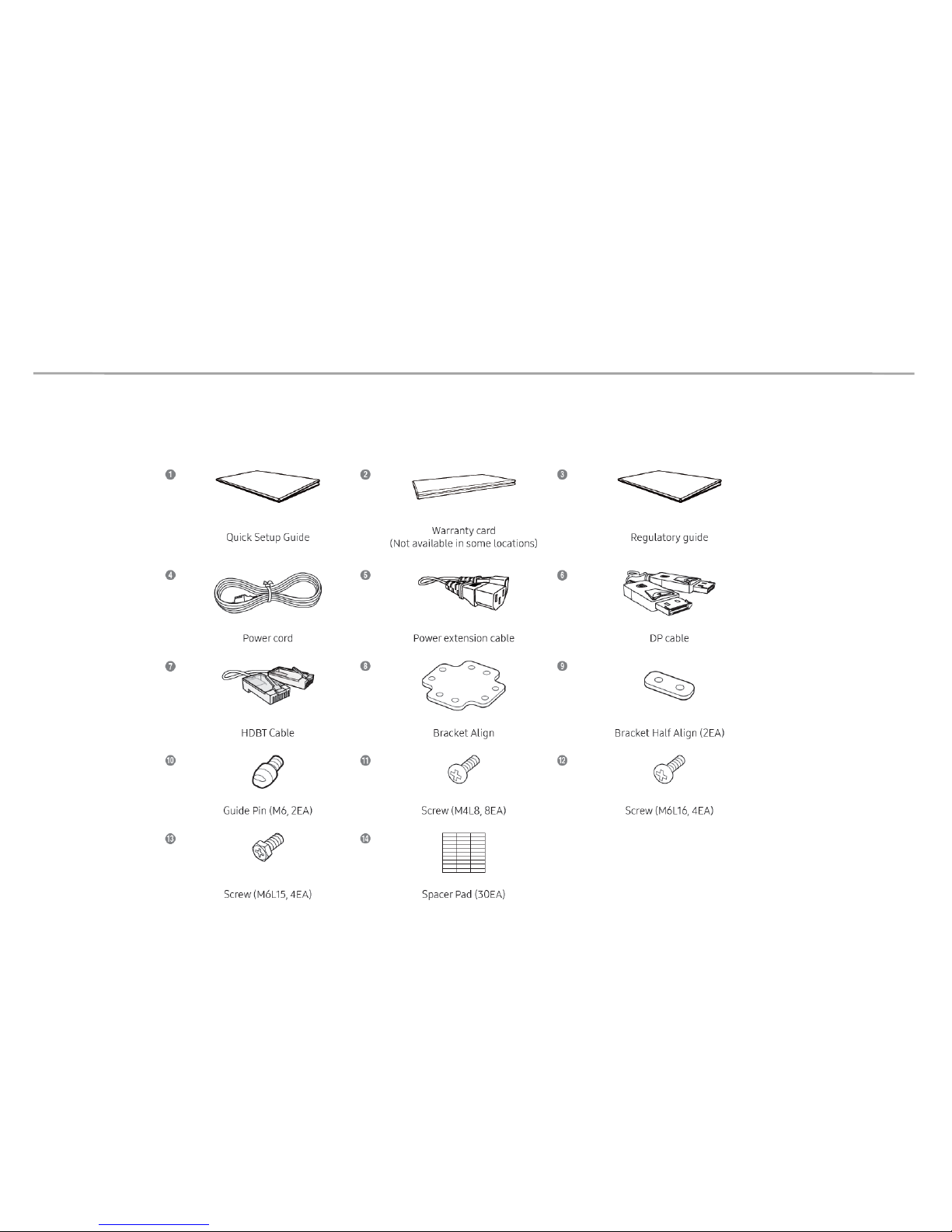
1-6 Accessary [Components]
2. How to install
2-1 How to handle (warning/caution)
2-2 Installation Requirements
2-3 Physical Installation
2-4 Data cabling
2-5 Power cabling
3. Example of Installation
4. Feature
4-1 PC Control Program
4-2 LED Color correction
Samsung Electronics LED Display Installation
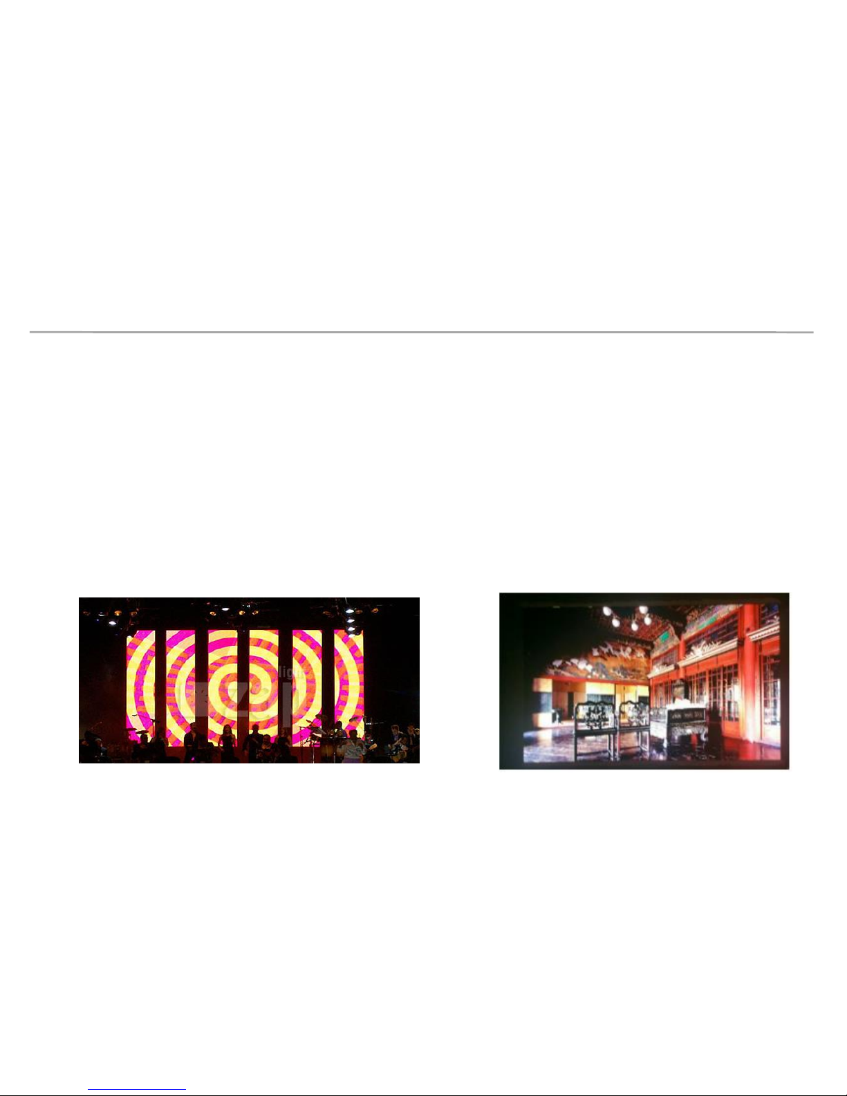
[Leeum, Samsung Museum of Art, P1.5 8x4]
1. Specification
1-1 Product Concept
1. LED Display of high-brightness for Indoors
- Product's lineup consist of 1.5mm ,2.0mm and 2.5mm pixel pitch.
- High brightness product for Indoor display(1.5mm/2.0mm 800nit, 2.5mm 2000nit)
- Various sizes of screen configuration
: Users can configure multiple size of screen by LED cabinet unit
Samsung Electronics LED Display Installation
1. Specification
1-1 Product Concept
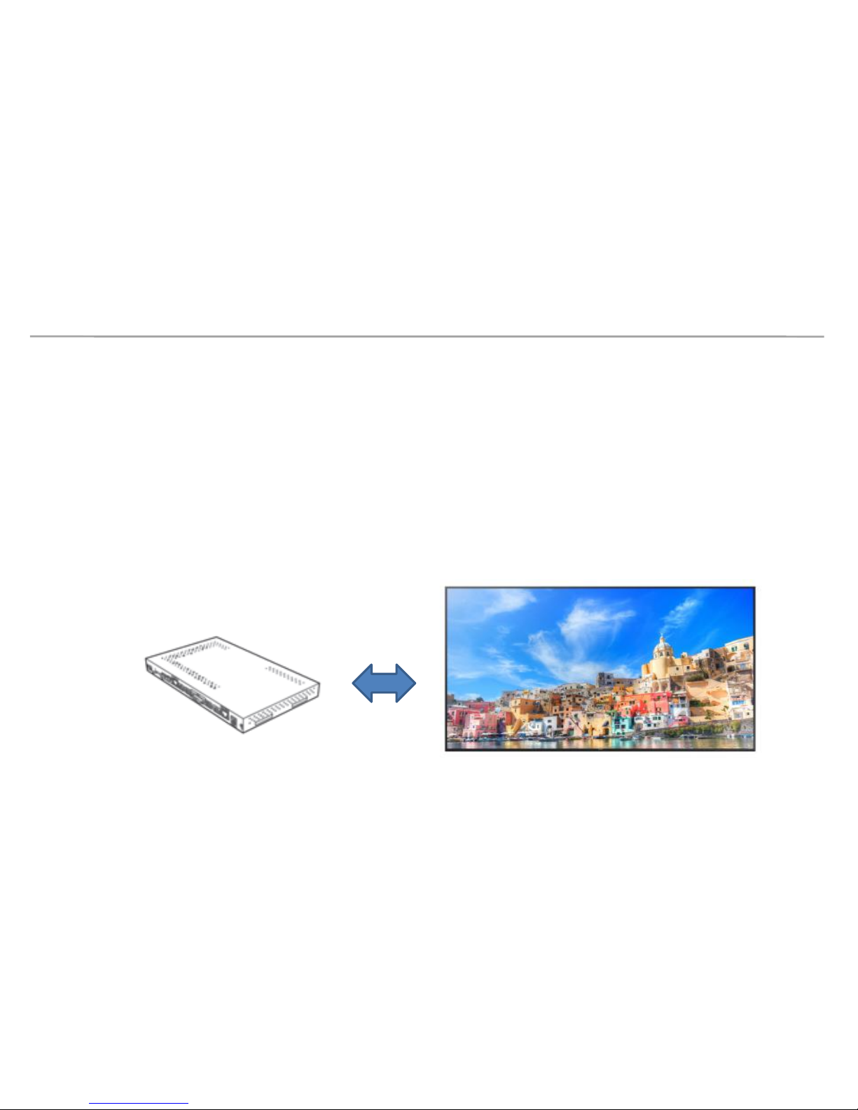
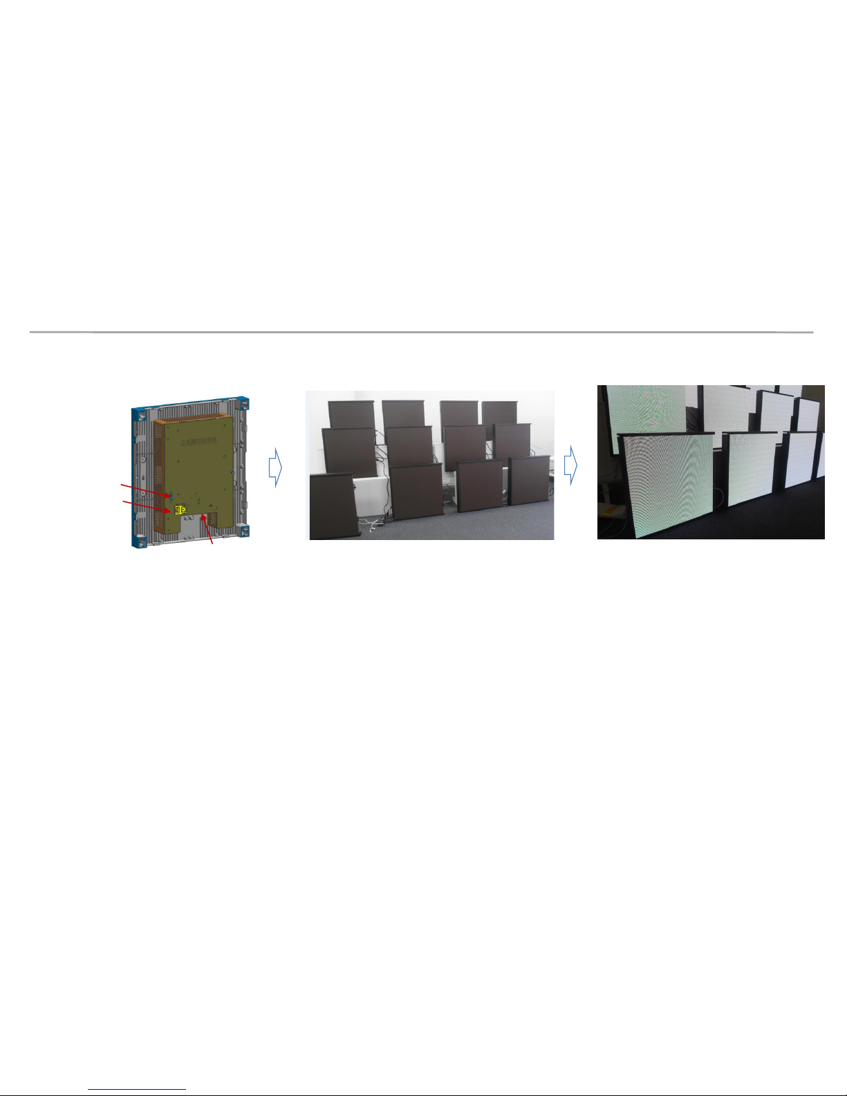
2. S-BOX solution for Picture Quality Enhancement and various video input
- Support various modes
- Able to adjust picture quality (Brightness, Contrast, etc.,)
- Support HDBT input and output for long distance video signals and control transmission
- Various input port : DP, HDMI, DVI, USB, RJ45
LED Signage BOX LED Display
Samsung Electronics LED Display Installation
Category
P1.5 Cabinet P2.0 Cabinet P2.5 Cabinet
LED
Cabinet
Pixel Pitch 1.5mm 2.0mm 2.5mm
LED Package RGB 3 In 1 1010 RGB 3 In 1 1010 RGB 3 In 1 2121
Pixel 320x360 240x270 192x216
Size 480x540x96.3mm 480x540x96.3mm 480x540x96.7mm
Area 0.26㎡ 0.26㎡ 0.26㎡
Aspect Ratio 8:9 8:9 8:9
Weight 9.2kg 9.2kg 9.2kg
Brightness (max)
Min : 25% of max
800nits 800nits 2,000nits
C/R 3,000:1 3,000:1 5,000:1
Brightness Level 15.5bit 15.5bit 15.5bit
Power Consumption 210W 210W 150W
Name of Work Temp 0~40℃ 0~40℃ 0~40℃
FHD Size 133.1”(3x6) 173.5”(4x8) 216.8”(5x10)
1. Specification
1-2 Specification
Samsung Electronics LED Display Installation
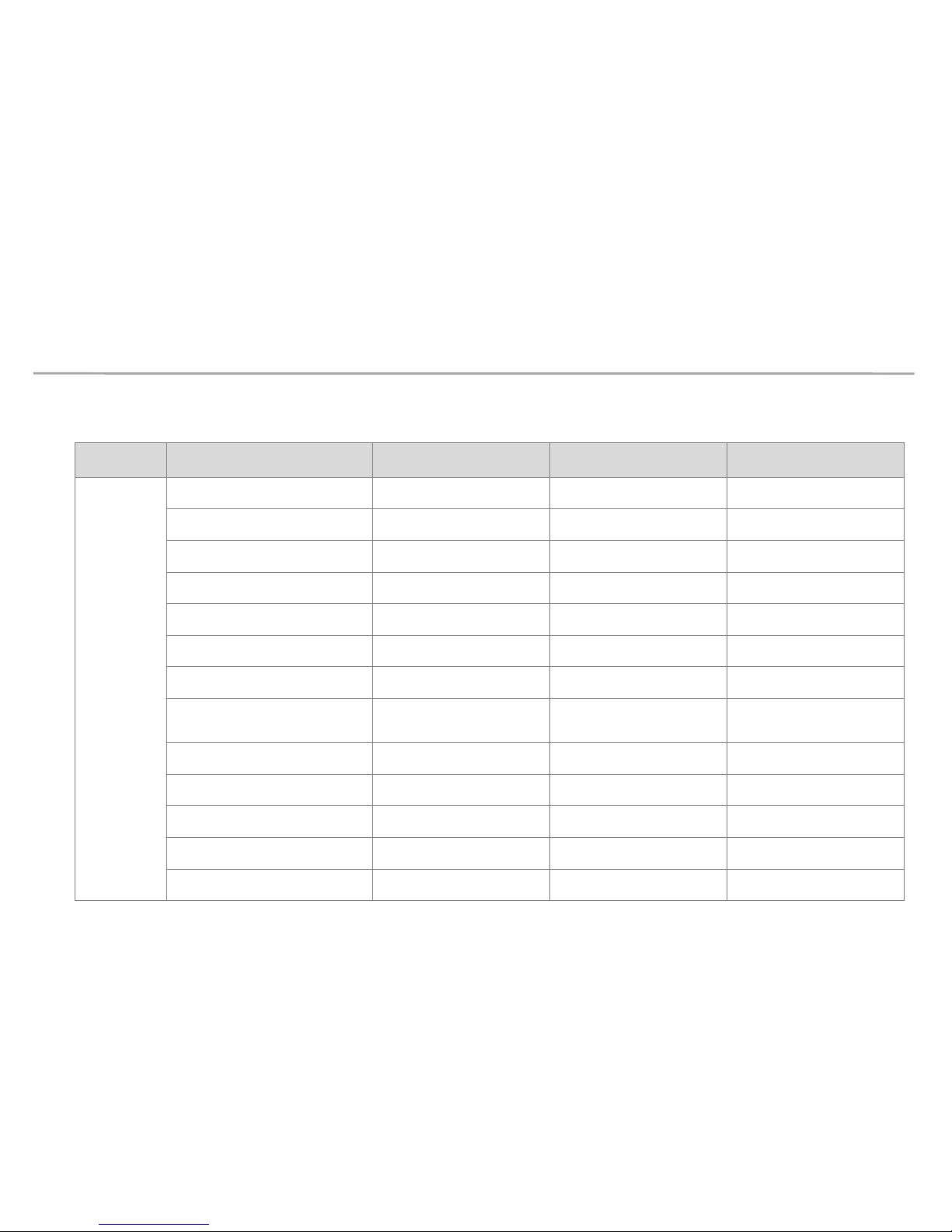
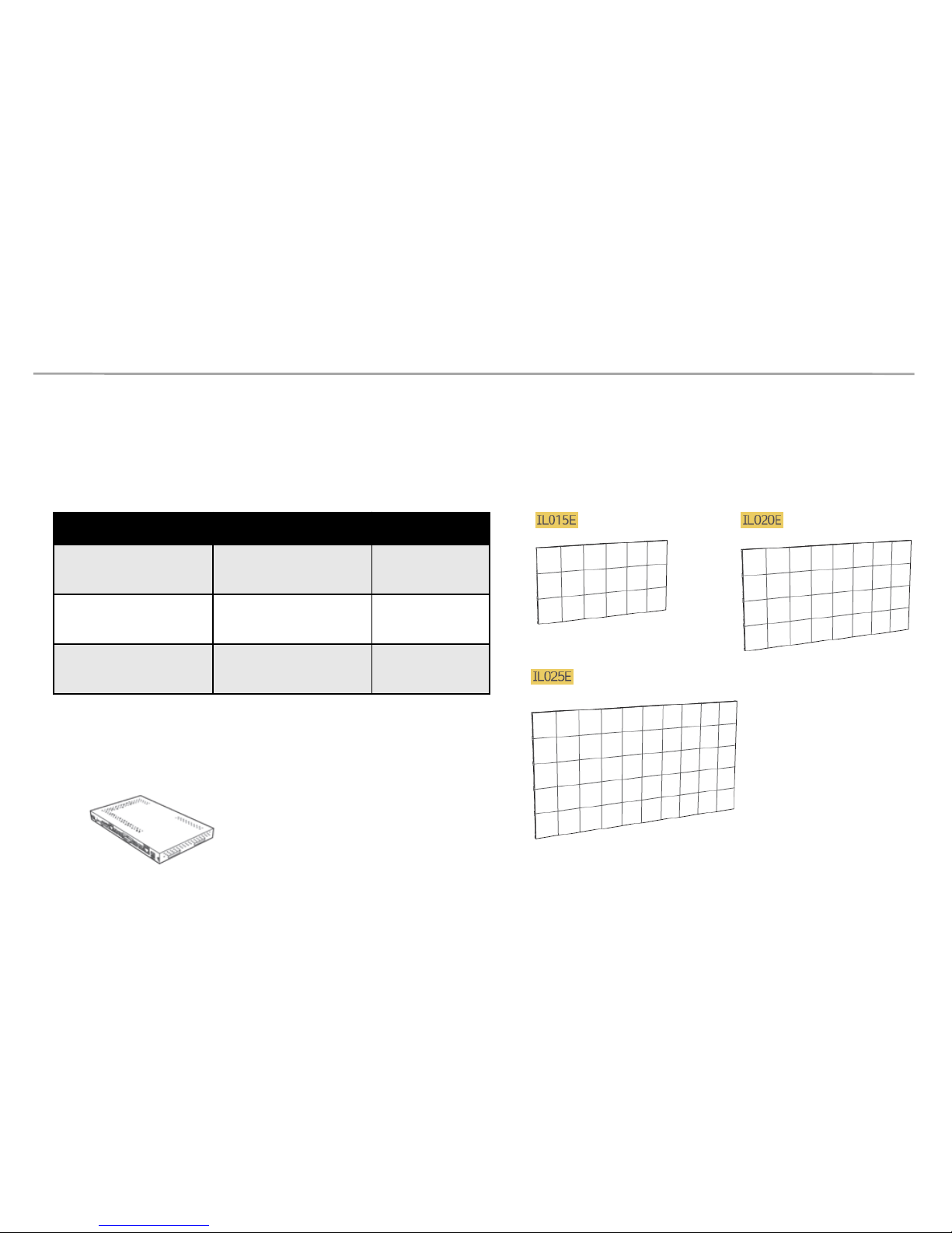
1-2 Specification
Cabinet Composition and the Number of Cabinets
in the standard of Full HD
SBB-IS08E Reference Picture
(LED Signage Box)
1. Specification
Model Cabinet SBB-IS08E
LH015I*****
(Pitch 1.5)
3 x 6 (18 units)
1 unit
LH020I*****
(Pitch 2.0)
4 x 8 (32 units)
1 unit
LH025I*****
(Pitch 2.5)
5 x 10
(50 units
)
1 unit
Samsung Electronics LED Display Installation
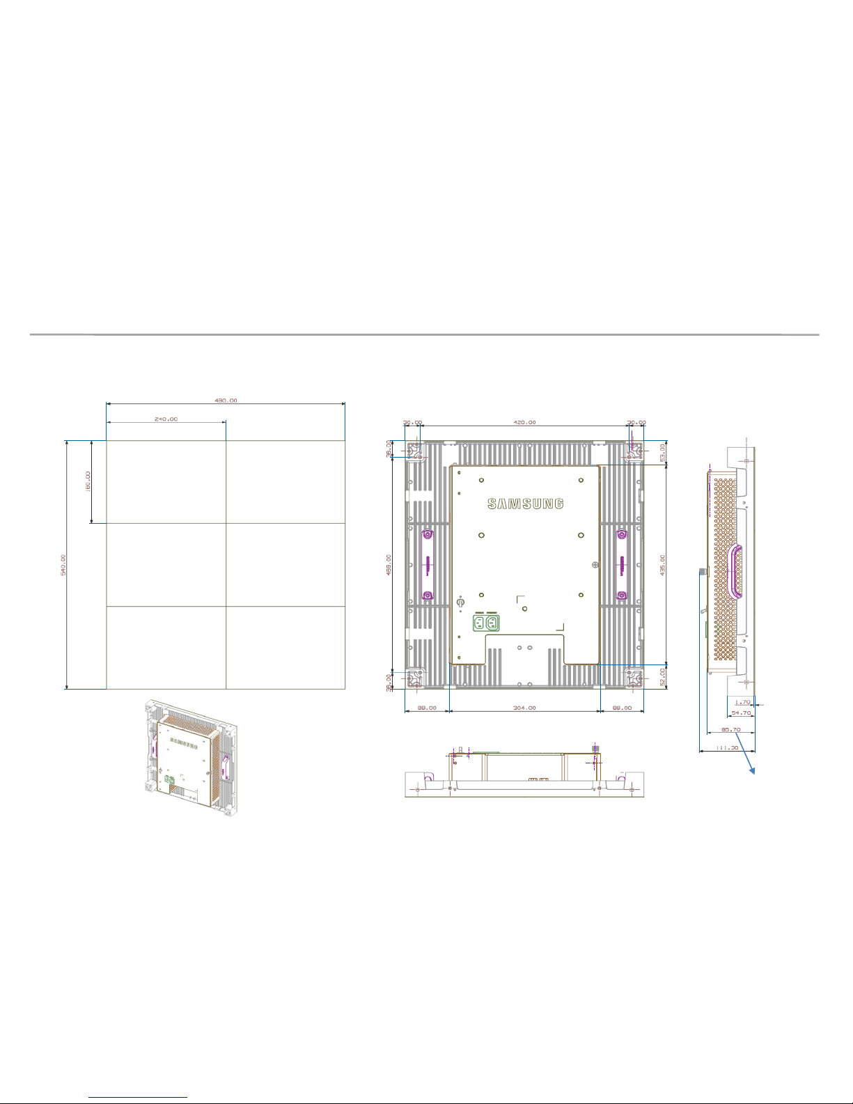
1. Specification
1-3 Dimension spec (unit : mm)
[except the depth of LED ]
P1.5/P2.0: 0.6mm
P2.5 : 1.0mm
Samsung Electronics LED Display Installation
1. Specification
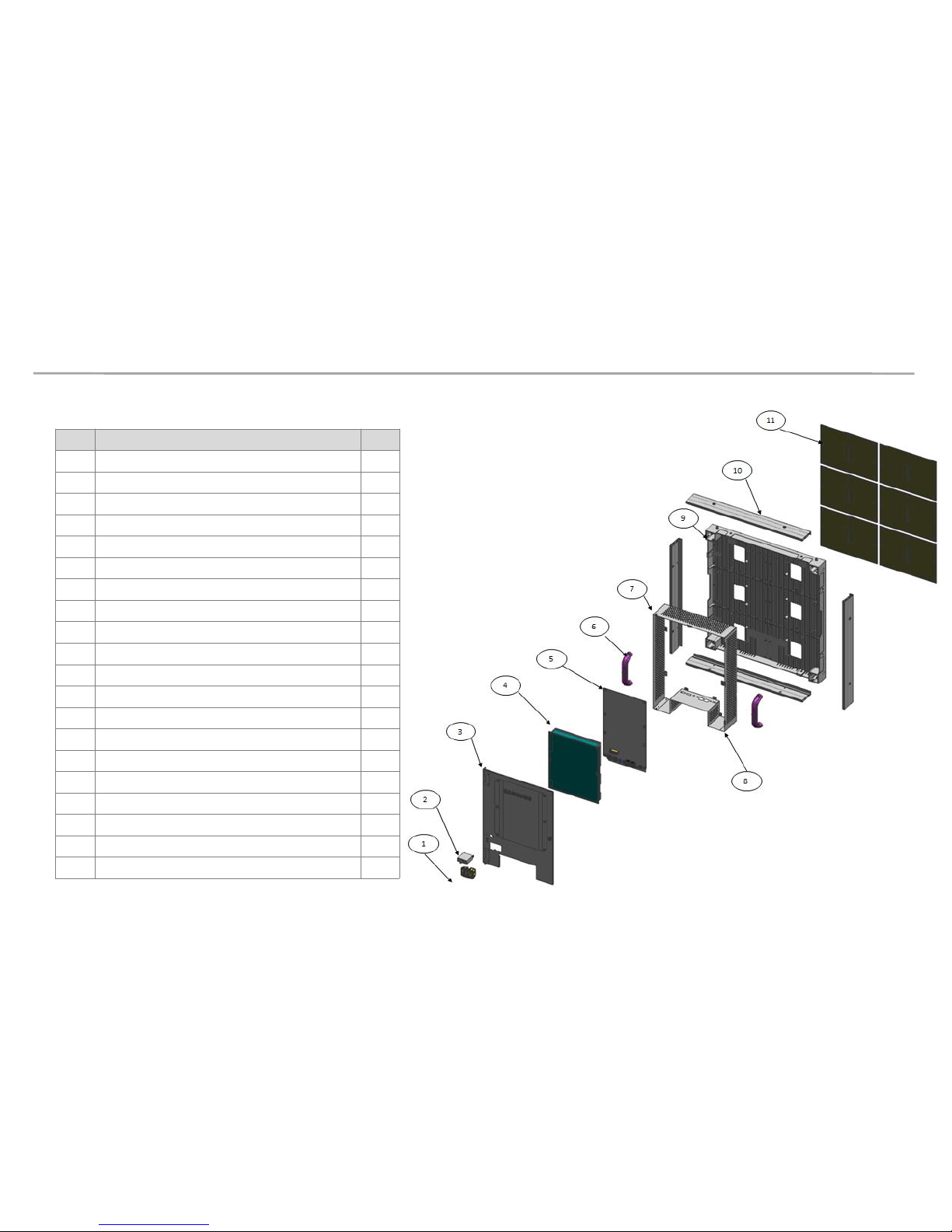
1-4 Exploded View
No.
Item
Qty.
1
POWER INLET
1
2
CIRCUIT BREAKER
1
3
ASSY COVER P
-REAR 1
3.1
COVER REAR
1
3.2
HINGE
2
3.3
CAPTIVE SCREW
1
3.4
SHEET INSULATOR
1
4
SMPS
1
5
MAIN PCB
1
6
COVER HANDLE
2
7
COVER FRAME TOP
1
8
COVER FRAME BOTTOM
1
9
ASSY BRACKET P
-FRONT 1
9.1
BRAKET
-FRONT 1
9.2
INLAY
TERMINAL 1
9.3
HOLDER
-WIRE 2
9.4
HOLDER MAGNET
48
9.5
MAGNET
48
10
COVER
-TOP
BOTTOM LEFT RIGHT
4
11
LED MODULE
6
Samsung Electronics LED Display Installation
1. Specification
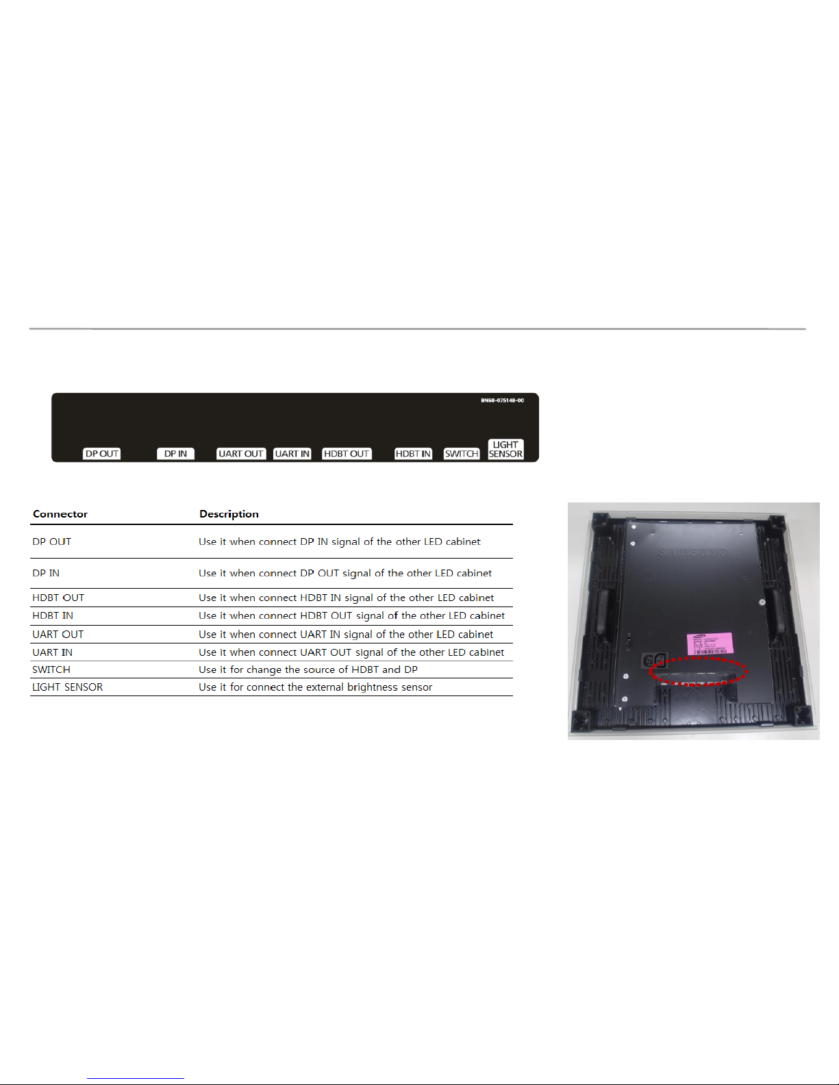
1-5 Viewing the Connection
Samsung Electronics LED Display Installation
1. Specification
1-6 Accessary [Components]
Components may vary based on the country.
Samsung Electronics LED Display Installation
2. How to Install
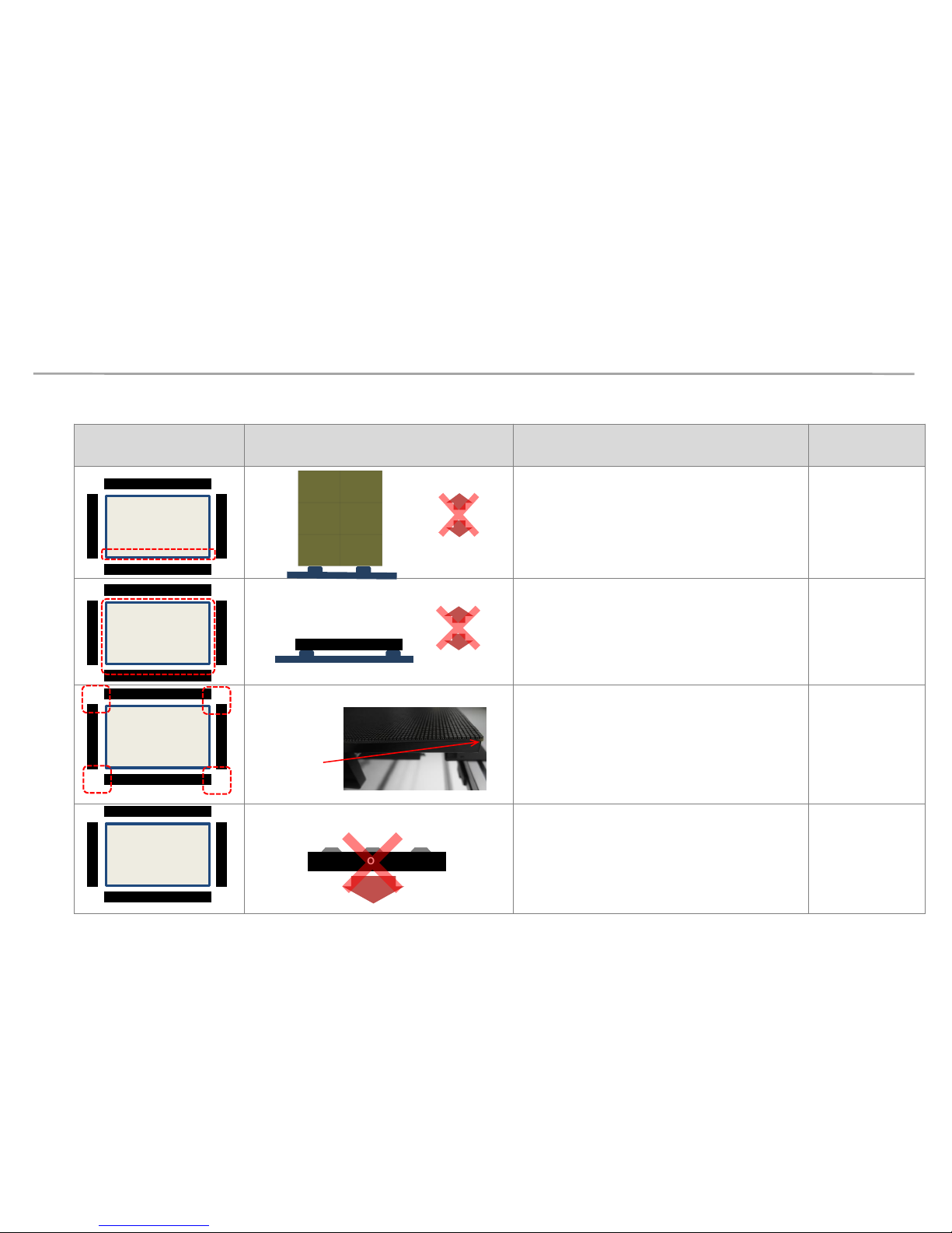
2-1 How to Handle (Warning / Caution)
Location Picture Cautions
Estimated
Failure Issue
[No Vibration, Shock or Drop]
▶
Do not give shocks to the LED side or
drop the SET after uncovering the
protection from the product before .
LED cracked
▶
Beware not to lay the product over a
vibrating subject or drop the set on the
back side of the product.
LED cracked
[Caution for Corner Damage]
▶
Beware of corner damage on the LED
module particularly, due to contacts on
the exterior.
LED cracked
[Do not let panel face down]
▶ Do not lay the product having the LED
side as the bottom side after uncovering
the protection from the product before
LED cracked
Front
Upper – Long
Right - Short
Left – Short
Lower – Long
MODULE
Corner edge
MODULE
Front
Front
Upper – Long
Right - Short
Left – Short
Lower – Long
Front
Upper – Long
Right - Short
Left – Short
Lower – Long
Front
Upper – Long
Right - Short
Left – Short
Lower – Long
MODULE
Samsung Electronics LED Display Installation
2. How to install
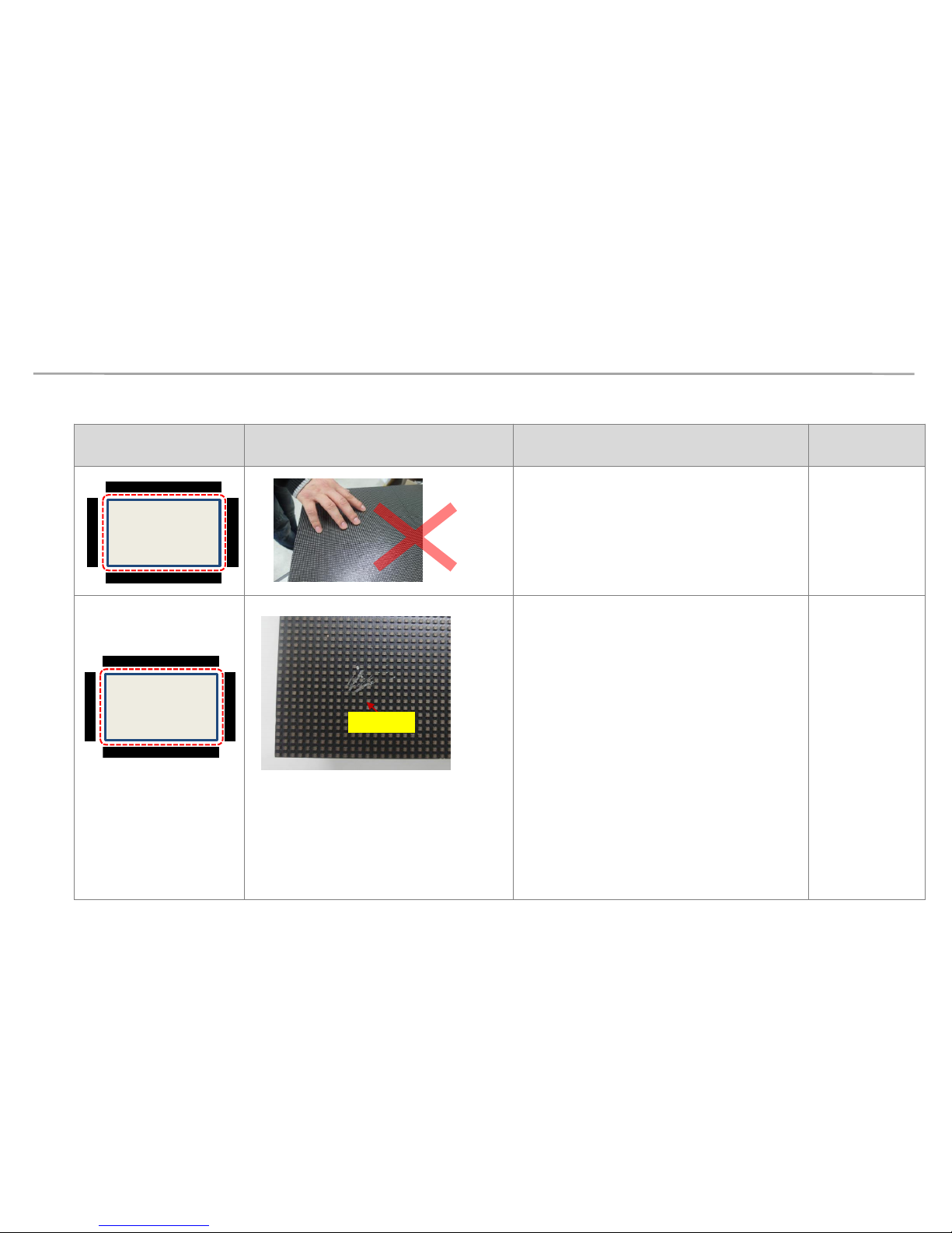
Location Picture Cautions
Estimated
Failure Issue
[Beware of LED Damage due to Static]
▶
Do not work on the LED surface with
hands not wearing antistatic glove
LED cracked
[Beware of LED Damage due to
Attachment of Metal Substances]
▶
There is magnetic on the front side of
LED. Beware not to have any metal
substances be attached to the surface.
▶
When any metal substances are
attached, use air gun or magnetic to
remove them. When you use magnetic to
remove the substances, the module may
be unlocked. So determine whether to
remove after separating it or having it
attached depending on the attachment
status.
LED damage in
the shape of
magnetic goods
that were used
during the
damage
Front
Upper – Long
Right - Short
Left – Short
Lower – Long
Front
Upper – Long
Right - Short
Left – Short
Lower – Long
Metal Dust
2-1 How to Handle (Warning / Caution)
Samsung Electronics LED Display Installation
2. How to install
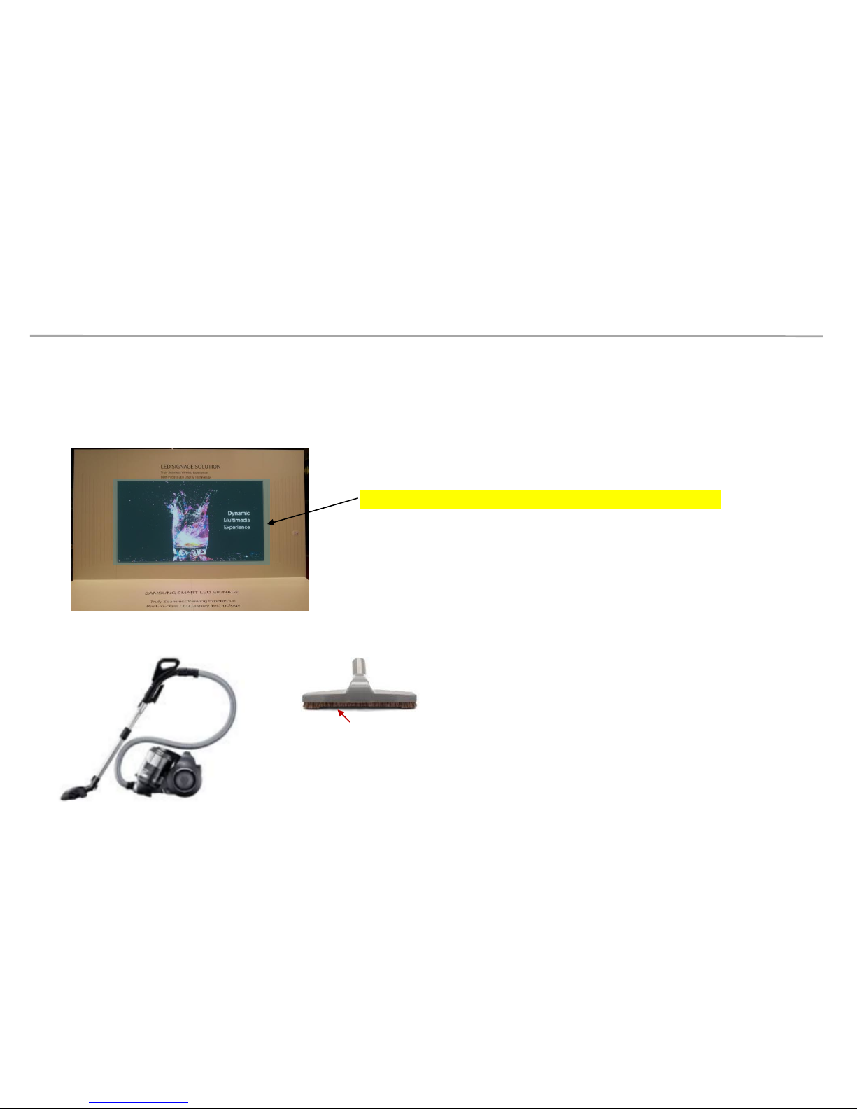
1. If LED display area is under construction, you should cover the LED surface with
protection sheet to prevent dust (metal dust) stick to LED surface.
LED surface must be cover if display area is under construction
2-1 How to Handle (Cleaning metal dust)
2. Clean dust on the LED surface with Cleaner machine (must use a soft brush head)
Soft brush
Samsung Electronics LED Display Installation
2. How to install
2-1 How to Handle (Cleaning metal dust)
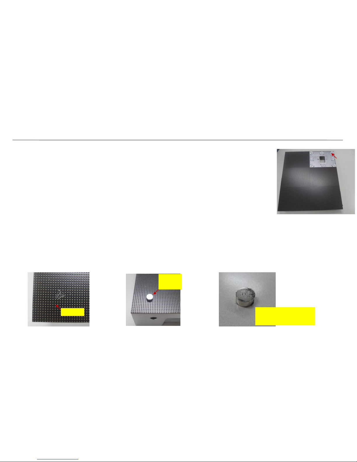
Magnet
3. Each LED Module have 8 magnet positions (picture 1)
So depend on environment , the metal dust may stick to LED surface.
So have to check the LED surface again at Magnet position.
Incase of Metal Dust stick to LED surface, we can remove it by
- Remove LED module with metal dust (Refer to page 45)
- Putting a magnet clock on LED surface
- Slowly move it around the metal dust area.
- Metal Dust will stick to Magnet Block.
- Remove Magnet Block and clean it for next times using.
Metal Dust
Magnet
block
Magnet block after
removing from LED surface
[Picture 1]

Samsung Electronics LED Display Installation
2. How to install
2-2 Installation Requirements (Circuit)
Samsung Electronics LED Display Installation
2. How to install
2-2 Installation Requirements (Circuit)
Static Electricity Precautions
Samsung Electronics LED Display Installation
2. How to install
2-2 Installation Requirements (Circuit)
Installation Precautions

Samsung Electronics LED Display Installation
2. How to install
2-2 Installation Requirements (Software)
- Desktop or Notebook PC installed with Operating System of below:
∙ Windows 7 32bit/64bit
∙ Windows 8 32bit/64bit
- Software
∙ .Net Framework 4.5 or above

Samsung Electronics LED Display Installation
2. How to install
2-2 Installation Requirements (Mechanical)
- Support structure for Product Installation
The types of support structure may vary, because it is determined differently according to
the customers’ taste and needs. Thus, spec all differs. Below items should be considered in
detail before is carried out.
1. Weight tolerances : Check whether the SET structure gets to be supported by the floor
or to be hung on a wall. Installation should be done considering the weight of the
product.
2. Environmental conditions : If the level of humidity and temperatures are high in the
surroundings, those conditions should be considered.
3. Locations : This product is for indoors, and should be located in a place where the
product is not likely to be affected by direct sunlight.
4. Ground stability
5. Front clearances: Check whether there are enough space and viewing angle in front of
the display to provide the most optimal impact to viewers.
6. Rear clearances : Needs to secure enough space to a worker in all kinds of structure.
7. Local regulations should be considered for each type of
Samsung Electronics LED Display Installation
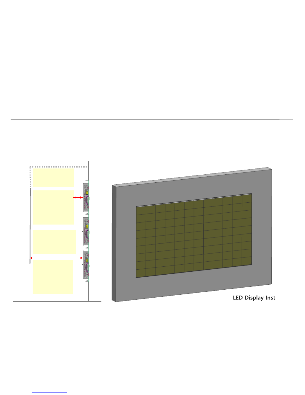
2. How to install
2-2 Installation Requirements
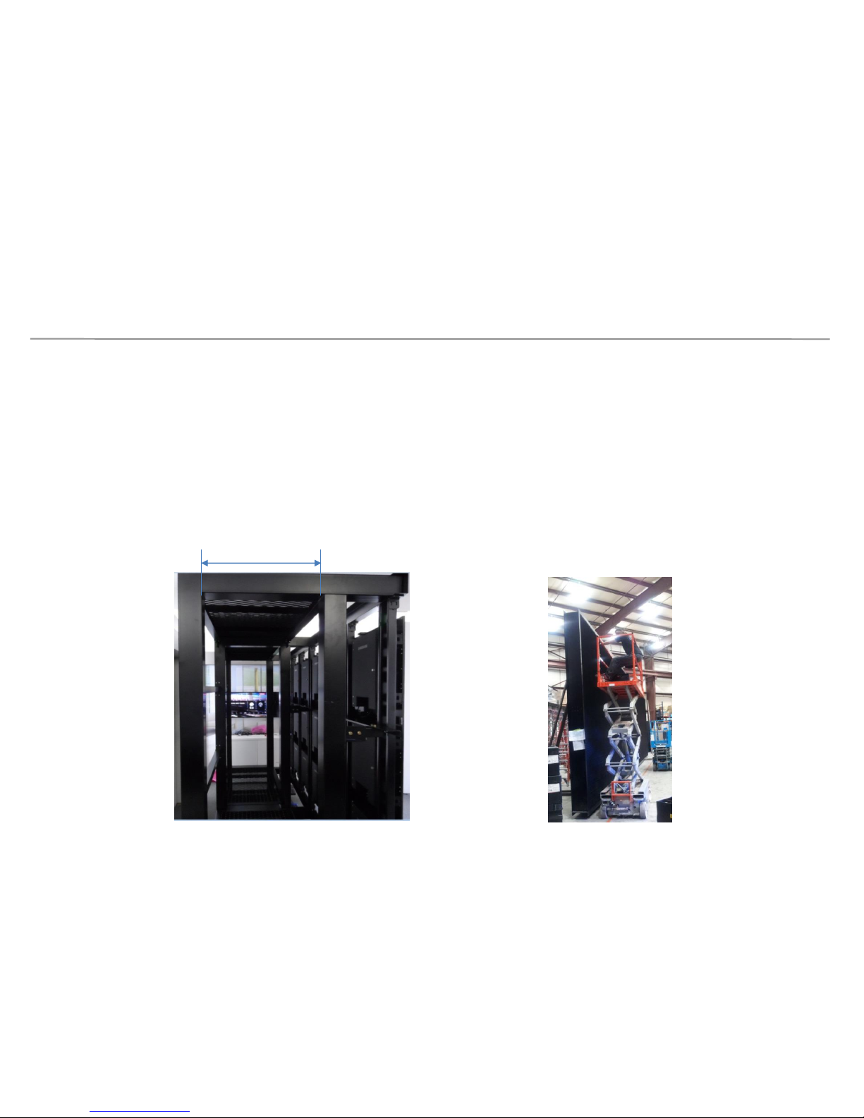
- Make sure to have enough space at least 60cm from the rear of set, when a
support structure is installed on the floor, to accommodate a worker and a tool,
for a example, ladder, etc. When the height of a structure is too high, Samsung
recommend to install ‘ Cat Walk’ at the rear of set and a lift in the front of set so
that workers can work easily in a high area.
At least 60cm
Cat Walk
Lift

Samsung Electronics LED Display Installation
2. How to install
2-2 Installation Requirements : Wall Mount Type
- When the support structure is fixed on the wall, make a big hole at the back of
the wall so that a worker can work at rear of set.
- When it is difficult to make a hole in the wall, apply a separate structure (ex:
wheel, hydraulic cylinder) on the set to enable moving the Cabinet.
- Check the status of the wall (Types, Thickness, Floor Plan)
- If the wall to have flat display installed is not flat, after , appearance quality may
become poor because the gap between the set widens.
- When the structure is installed in a pocket shape, the surrounding temperature
should be maintained below 35C degree and it is recommended to make more
than 10cm of space from the wall.
Samsung Electronics LED Display Installation
2. How to install
2-2 Installation Requirements : Thermal condition
- Operation Ambient Temperature in the standard of one product unit : 0~40℃
- If less than three stores vertically in LED Cabinet, recommended external temperature below 35℃
If exceed over three stores vertically in LED Cabinet, recommended external temperature below 30℃.
- If impossible to secure enough space for absorption/emission of air as recommended below,
install Fan or Air-Conditioner and have the backside area of LED Cabinet not exceed 40℃ at maximum.
The 30mm point
at the central
back area of the
SET to be
managed below
Max 40℃.
Secure enough
working space
and heat
rejection area at
the back area of
the SET.
Do not close the
upper side of the
back in the SET.
Secure space for
absorbing air at
the back under
area of the SET.

Samsung Electronics LED Display Installation
2. How to install
2-2 Installation Requirements : Free space behind the Set
Door open: 480*540*379mm
=> FREE SPACE behind Cabinet should
be over 300mm for door opening space.
Door open
379
540
480
300
Samsung Electronics LED Display Installation
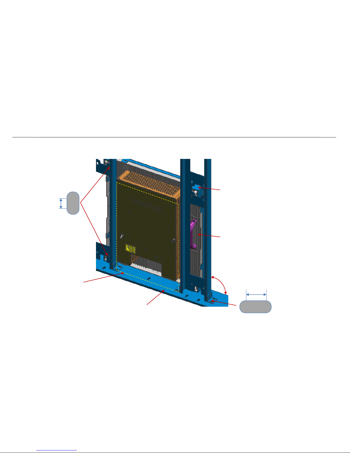
2. How to install
2-2 Installation Requirements : Standard Installation Frame
Free space for Door opening
Flat base
Hole for handles and
Hex bolt
Open space for
Bracket Align
Rounded rectangle hole for Frame
position left-right adjustment
Rounded rectangle
hole for SET fixing
10.0mm
8.0mm
Vertical frame
90°
Samsung Electronics LED Display Installation
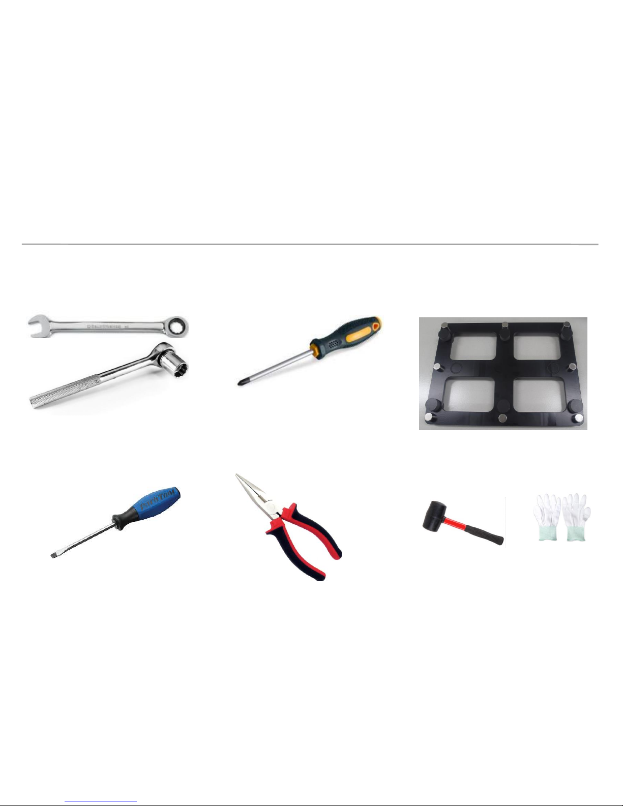
2. How to install
2-2 Installation Requirements : Tool for Installation
OR
Wrench 10.0mm
socket ratchet
Phillips head crew driver
Pliers
LED MODULE JIG
(model name: CY-LJFNAS)
Flat head crew driver
Rubber
hammer
Antistatic
Glove
Samsung Electronics LED Display Installation
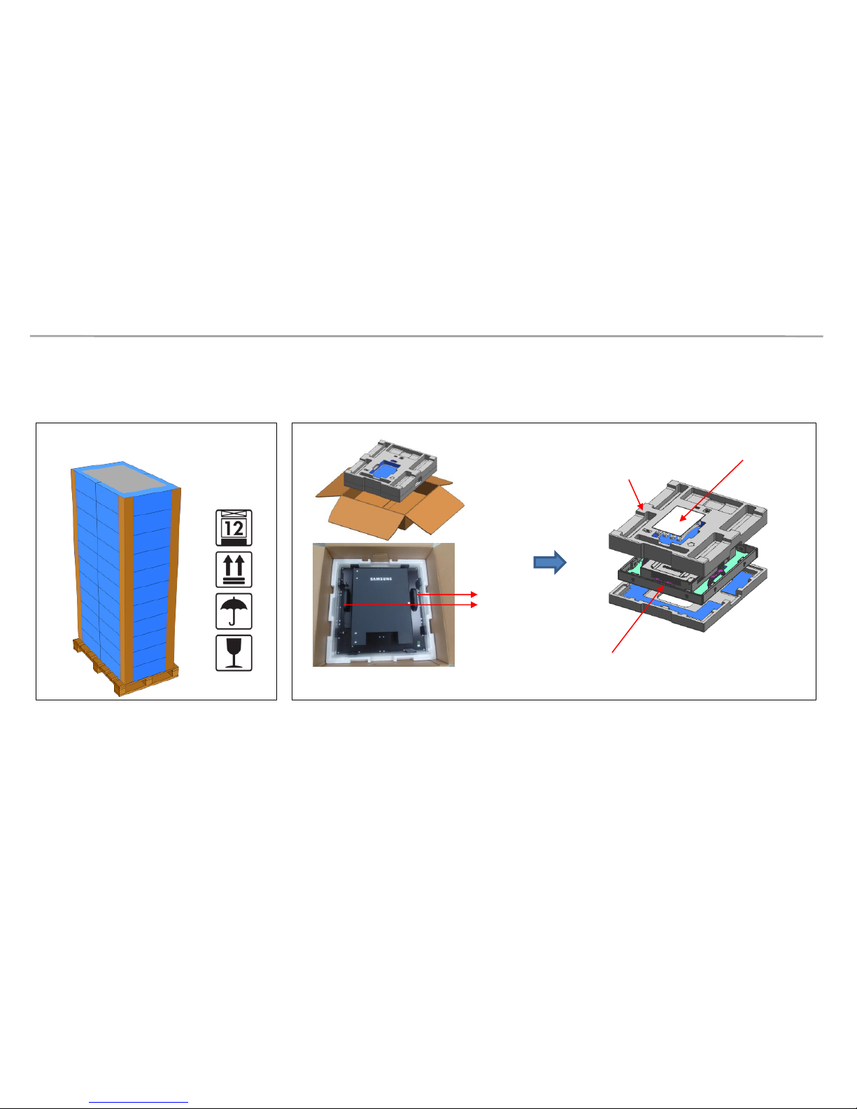
[ Before Unpacking ]
[ Unpacking ]
2. How to install
2-3 Physical Installation : Open Packaging
Stack to maximum 12 layers
IB & cable
LED set
Top-Cushion
handle
1) Remove the tape from the upper side of the box, and then open up.
2) Remove the Top–Cushion
3) Take out the set while holding the handle inside the PE-Bag, and then remove the
PE-bag
* Do not keep the LED display face down to ground
Samsung Electronics LED Display Installation
2. How to install
Connect Power Cable to SET
Use internal pattern to check dead pixel or any damage with screen
* Internal white pattern :
- Turn on Power
- Push Source button 5 seconds and release,
- Wait for display, push one more times. (color rotation : W -> R-> G -> B)
2-3 Physical Installation: Check the SET Condition
Source Button
Power Switch
Power Inlet
Samsung Electronics LED Display Installation
2. How to install
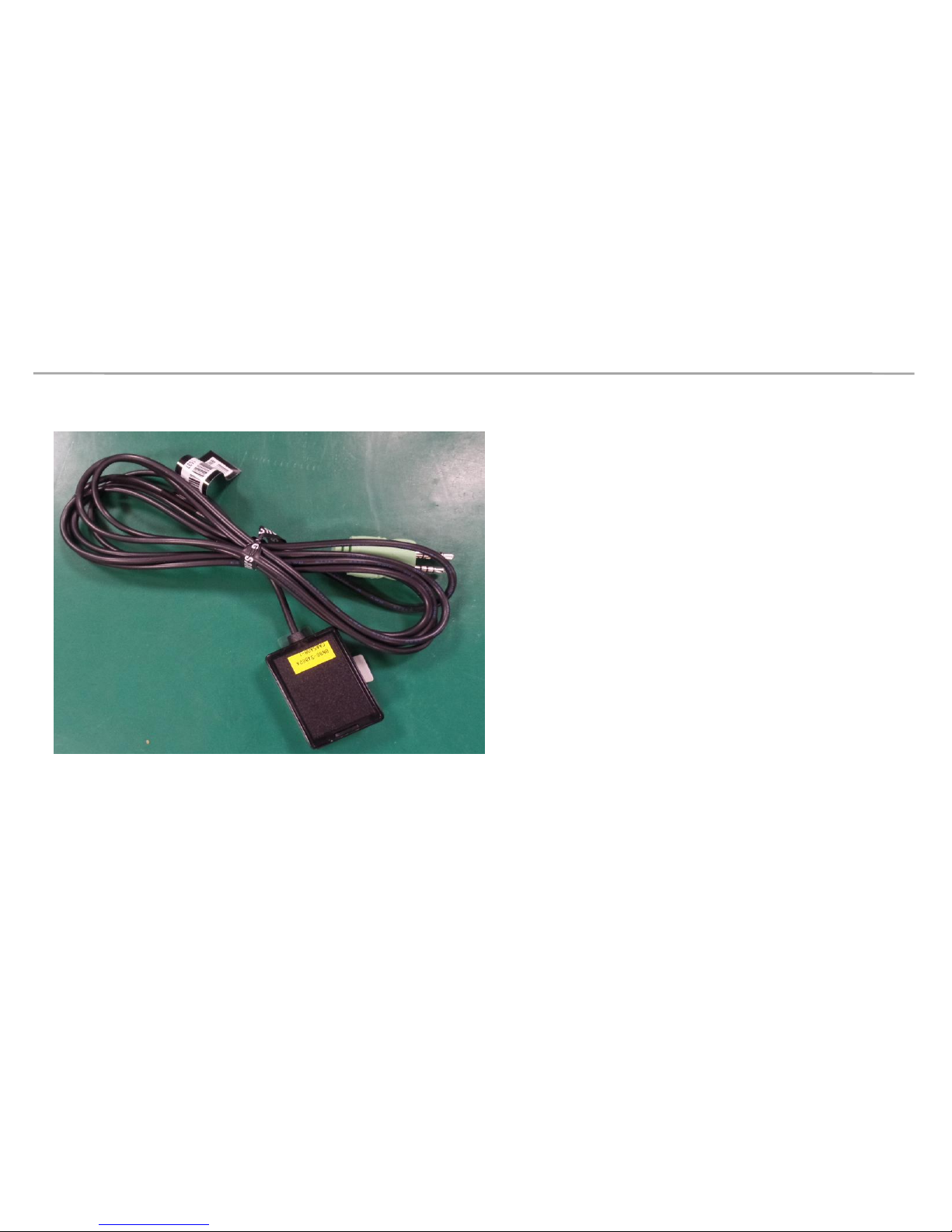
2-3 Physical Installation: Illumination Intensity Sensor Introduction
Sensor for
Illumination
Intensity
If the sensor for illumination intensity is
needed, secure enough space for the
location of sensor and the place for
assembly, and have it be attached on
the edge of the display.
(As the sensor area has magnetic
properties, able to be attached on the
metallic objects.
Illumination Intensity Sensor is included
in LED Signage Box accessory)
Samsung Electronics LED Display Installation
2. How to install
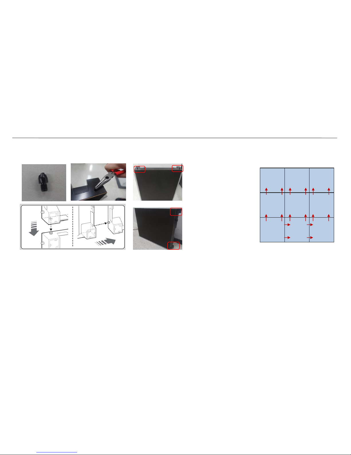
2-3 Physical Installation: Stud-Guide Introduction
9 7 8
6 4 5
3 1 2
Example: 3*3 cabinets
Bottom row: side use
From 2nd row: Top use
Stud guide used to guide position between 2 cabinets. (tolerance 0.2mm)
- For bottom row use them on side(Left-right)
- From the second row use it on Top (refer example picture)
Tool : Plier
Samsung Electronics LED Display Installation
2. How to install
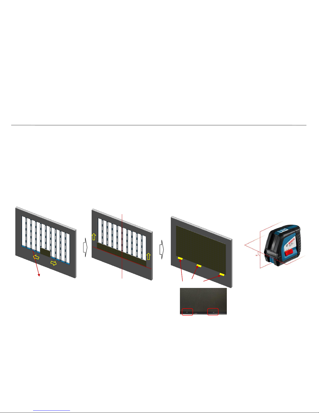
2-3 Physical Installation: Base Guide
It is more convenient to install from the bottom to the top side when the sets are
to be installed on a floor.
- First row alignment is most important
- Must use line lasers level tool to align Vertical / Horizontal
- When rubber pad or a bracket is input between bottom of LED module and a cover-frame,
it can reduce a gap of module~module by preventing a sagging of LED module.
(Refer to the bottom figure and page 70)
line lasers
line lasers level tool
Base Guide side
Rubber pad
 Loading...