

Samsung LH008IWJ Series Installation Manual

Samsung Electronics
LED Display
Installation Manual
LH008IWJ*** (P0.84)
SNOW-18010U
Ver. 1.4
Samsung Electronics
Check first before Installation (1/2)
1
• For HDBT signal stability, use the cable above CAT6 *STP, *FTP level. ( Length 15m~100m )
- Do not use “comb” or “pinstripe” cable.
“CAT6 UTP can not be allowed”
• All Power cables and OCM cable must be connected firmly
• Do not mix cabinet which have different Project number, each cabinet have its own project
number.
Module Cabinet
Box

Samsung Electronics
Check first before Installation (2/2)
2
• Install the device only using SNOW-1810U and its supplied IG.
※ Please check below Cabinet and S-box compatibility table information
S-Box
SNOW-1810U
SNOW-1703ULD
SNOW-1703U
I/G
BN91-20525A BN91-19993A BN91-19100A
Cabinet
IF015H,
IF020H,
IF025H,
IF025H-D,
IF040H-D,
IF060H-D,
IF012J,
IW008J
IF015H,
IF020H,
IF025H,
IF025H-D,
IF040H-D,
IF060H-D,
IF012J
IF015H,
IF020H,
IF025H,
IF025H-D,
IF040H-D,
IF060H-D

Samsung Electronics
Table of Contents
1. Product Information and Precautions for Installation
2. Check Point about the Radiant Heat
3. Preparation for Cabinet Installation
4. Frame Installation
5. Cabinet + Frame Installation
6. Disassembly & Front Service
7. S-BOX Installation and Connection
8. Settings and How to Use
9. Issue and Solution
10. Cable Connection
11. Bezel Installation
3

Samsung Electronics
Fig.3 S-Box Fig.4 I/G
(Interface Gender)
◇ Frame Kit Composition (Refer to Page 16)
1. Product Information and
Precautions for Installation
Frame Kit Composition Note
VG-LFJ08SWW
1x1 (1 Set)
-
VG-LFJ08FWW
2x2 (4 Set)
FHD Installation
VG-LFJ08TWW
3x3 (9 Set)
-
VG-LFJ08UWW
4x4 (16 Set)
UHD Installation
◇ SBB-SNOWJAU (S-Box, I/G)
◇ Cabinet Product Information
4
<1x1>
<2x2>
<3x3> <4x4>
※ Power system should be designed
according to Screen composition. 1 FHD
Screen should be in same power system.
(Refer to page 19 )
Samsung Electronics
◇ Storage Condition
1. Product Information and
Precautions for Installation
5
◇ Pre-heating Process
should be conducted before installation& operation after storage. (refer to page 18)
Condition Value Recommend
Temperature -20℃ ~ +45℃ -20℃ ~ +45℃
Humidity 5~95% 5~65%
Hight 3000m 3000m
Step condition Brightness Time
1 Lighting up display with 10 gray scale 5% 2 hr
2 Lighting up display with 20 gray scale 8% 2 hr
3 Lighting up display with 30 gray scale 10% 2 hr
4 Lighting up display with 40 gray scale 15% 2 hr
5 Lighting up display with 50 gray scale 20% 2 hr
6 Lighting up display with 70 gray scale 25% 2 hr
7 Lighting up display with 90 gray scale 35% 2 hr
8 Lighting up display with 120 gray scale 45% 2 hr
9 Lighting up display with 150 gray scale 60% 2 hr
10 Lighting up display with 180 gray scale 70% 2 hr
11 Lighting up display with 200 gray scale 80% 2 hr
12 Lighting up display with 255 gray scale 100% 2 hr
Samsung Electronics
1. Product Information and
Precautions for Installation
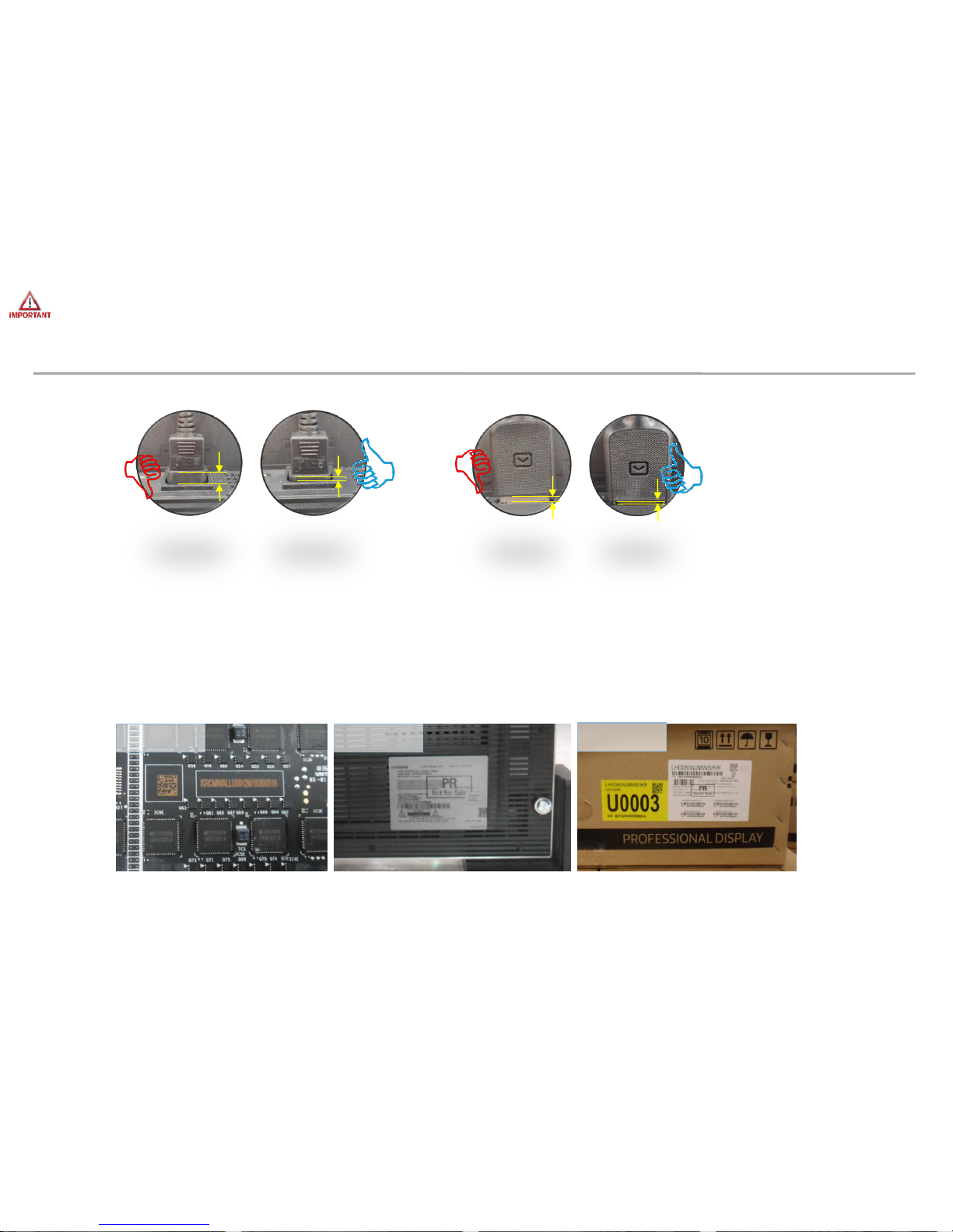
• Precautions for Installation (LED damage)
6
Caution Image
[ Beware of Outside Impact, Fall]
① Beware not to cause any impact on the LED screen or drop the product on the floor
after the protection gets taken off for installation.
② Beware not to put the LED side headed downwards to the floor after the protection
gets taken off for installation.
③ Beware not to have the corner area of LED module be damaged due to the contact
with the outside.
④
Beware not to put more than 12 layers.
①
②
③
④
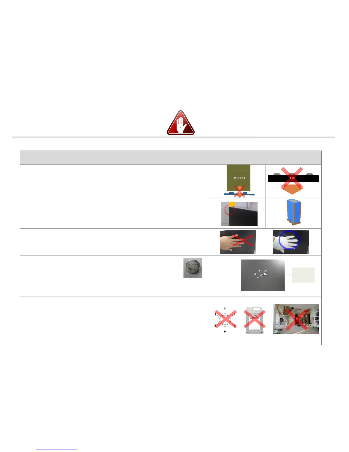
[Beware of LED Damage due to Static Electricity]
▶
Beware not to touch LED screen with bare hands without putting gloves on.
[Beware of LED & Film Damage due to Metallic Substances]
▶
Beware not to have metallic substances pulled in to the surface
due to the magnetic force on the front side of the LED.
▶
If any metallic substances get drawn in on the surface, please disassemble the
module and then remove the pollutants by using a magnet.
[Beware of LED Damage due to chemicals.]
▶
Beware not to contact water, waxes, benzene, thinners, mosquito repellents,
lubricants, cleaners, solvents or surfactants on LED.
▶
When installing on the construction site, it should be installed after construction & cleaning.
▶
If the installation site requires construction work, the product is covered with a
curtain and operated 50% white or video for 2 hours every day.
MODULE
Front
LED &
Film

Samsung Electronics
1. Product Information and
Precautions for Installation
◇ Caution for cleaning screen
7
- Wipe lightly with the soft cleaning cloth provided with the product
(Watch out for surface LED damage)
- Hard stuff on screen surface can damage LED chip and film during cleaning.
Clear screen surface before cleaning
- Watch out for damage when cleaning gap between HalfCabinets
- Watch out for damage when cleaning gap between Modules
- Do not insert any cleaning tool or spay cleaner directly into
the gap
- Do not wipe the LED surface with hard materials such as
paper towels, brushes comb or brush, acrylic or steel.
- Do not use chemicals such as wax, benzene, cinna, mosquito
repellent, air freshener, lubricant, and detergent in products
(Recommendation: Use of glass detergent for alcohol or
surfactant)
★Caution★

Samsung Electronics
1. Product Information and
Precautions for Installation
• Preparations for Installation
8
MAGNET JIG
(BN81-17114A)
(-) (+) driver
Absorber
(BN81-17124A)
Adjustment tool
(BN81-17112A)
GAP-TOOL
(BN81-17113A)
Glove
(RA00400E-002539)
Hex Wrench
2mm, 6mm
PLIER
(BN81-17541A)
• Provided in Frame Kit. (VG-LFJ08*WW).
• Provided in accessory kit. (CY-WJJPWP).
Samsung Electronics
2. Check Point about the Radiant Heat
9
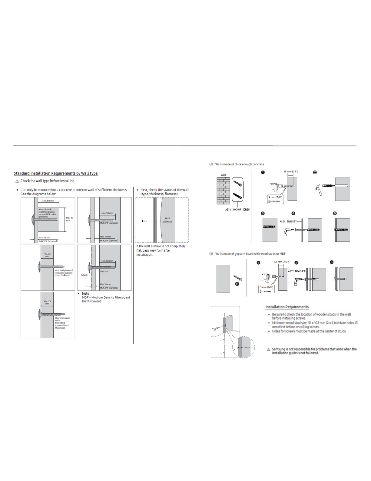
Standard and condition for indoor installation
- Standard for using ‘SAMSUNG WALL MOUNT’ (Fulfill ADA)
∙ The gap between the front of a product and a wall: 98.6mm
∙ The gap between the back of a product and a wall: 26.1mm
- When sunlight enters
∙ If a sunlight enters through a window or outside walls of a building,
an additional inquiry is needed.
- The effect of warm/cold air from a duct system
∙ Make sure the warm/cold breeze(especially warm air) from a duct system not to affect a product.
- The measuring location for ambient temperature
∙ Either right in the center of a product or Air inlet part
※ ADA(American’s with Disabilities Act
98.6mm
26.1mm
wall
Measuring
location for
ambient
temperature
Measuring
location for
ambient
temperature
※ Written under ‘Full white, (back light 7)’ standard
Written under ‘Video, (back light 10)’ standard
◇ Ventilation Guide
Samsung Electronics
2. Check Point about the Radiant Heat
10
Minimum spacing for buried installation
(Specification for no Fan & Samsung Frame Kit installation)
Min 60mm
WALL
Min 60mm
Airvent area
Min 60mm
Min 60mm
Min 60mm
Air vent area
Min 300mm (floor)
Min 500mm (ceiling)

Samsung Electronics
2. Check Point about the Radiant Heat
11
Minimum spacing for wall installation
(Specification for no Fan & Samsung Frame Kit installation)
WALL
Min 90mm
Min 300mm (floor)
Min 500mm (ceiling)
Airvent area
Airvent area
Airvent area
Airvent area
Samsung Electronics
2. Check Point about the Radiant Heat
◇ FAN Using condition
- Air Vent : install at bottom
- Top: Seal except fan hole
FAN
Seal except fan hole
WALL
FAN
좌우측면 밀폐
A
B
d
c
◇ Vent specification
Using over 70% open ratio vent
- Open ratio (%) =
𝑐 𝑋 𝑑 𝑋 𝑁𝑜. 𝑜𝑓 𝑣𝑒𝑛𝑡 ℎ𝑜𝑙𝑒
𝐴 𝑋 𝐵
Seal right and left side
12
Air vent area
(Bottom only)
Samsung Electronics
13
Under 30℃ Guidance
Columns
Rows
2. Check Point about the Radiant Heat
※ SAMSUNG WALL MOUNT , Full white, back light 7, VENT 60%
8
7
6
5
4
3
2
1
1 2 3 4 5 6 7 8
FAN
unnecessary
Samsung Electronics
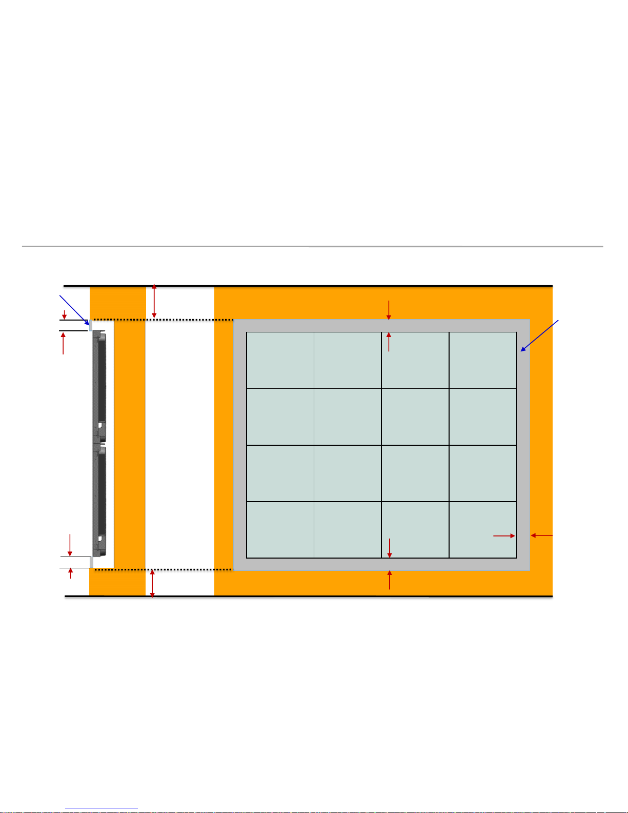
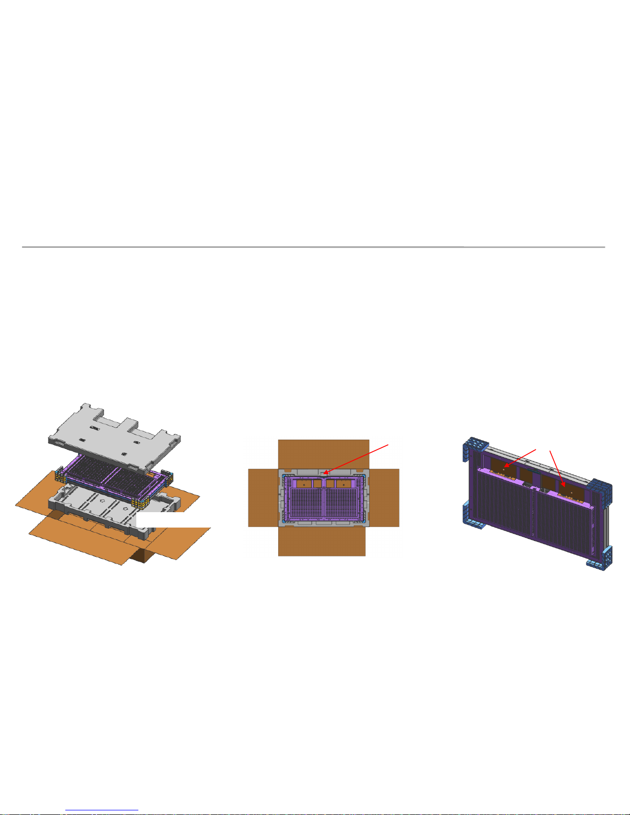
3. Preparation for Cabinet Installation
• Preparations Before Installation
14
① Remove the Box tape at the upper area and then open up the box. (Fig.2)
② Remove the Top–Cushion and hold the handle inside PE-Bag and pull out the set then remove PE bag.
(Fig.2)
③ Check whether there is any abnormality on the screen by connecting the power cable.(Fig.3)
※ Process of Screen check (Page.14)
Fig.1 Packing & Product
Fig. 2 Opening up
HANDLE
BOX
CUSHION-TOP
CUSHION-BOTTOM
LED-SET
Fig.3 Check the Screen
SWITCH
Samsung Electronics
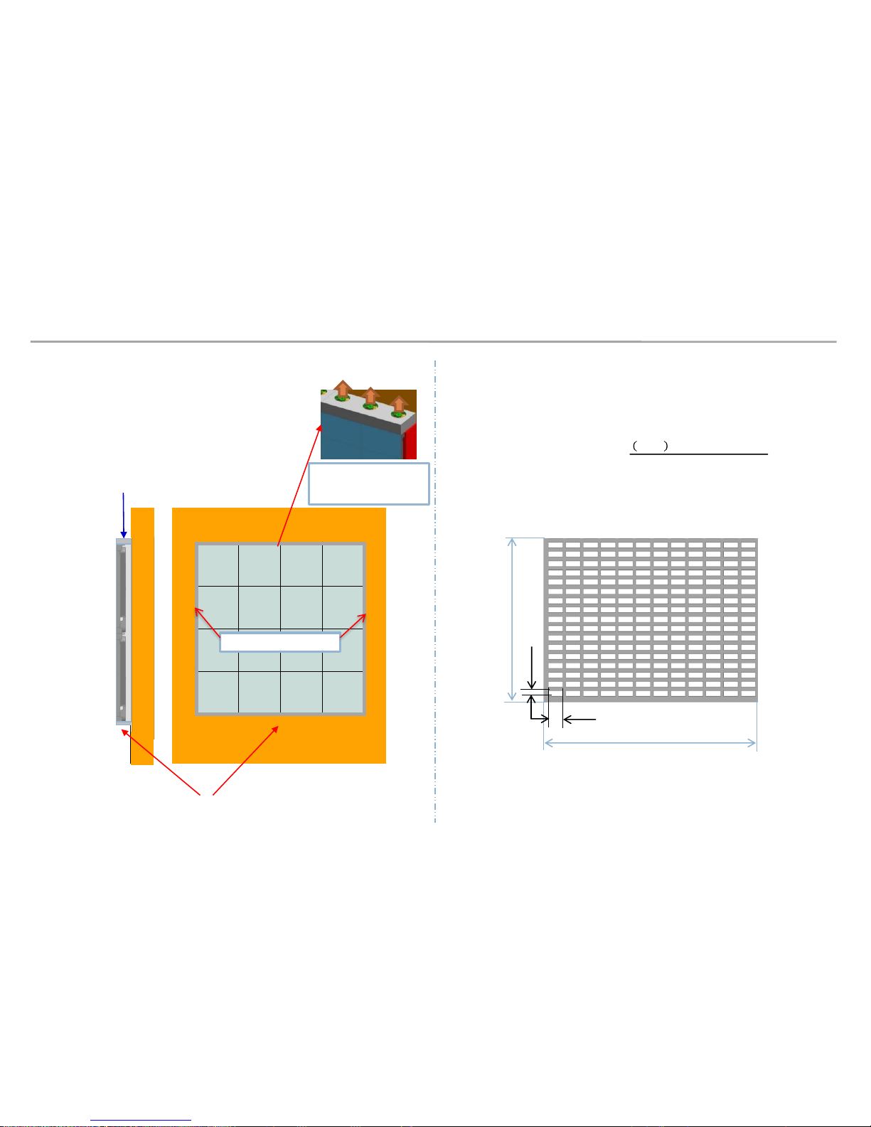
3. Preparation for Cabinet Installation
15
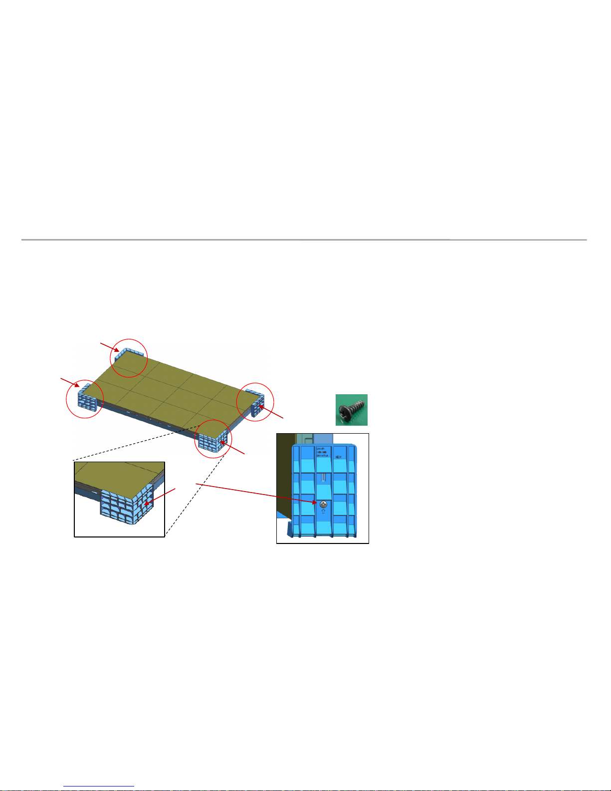
④ Unfasten the 4 screws on the Cover Corner area to separate those screws and
Remove the protective sheet attached to the two sides (Top/Bottom). (Fig.4)
Fig.4 Cover Corner Removal
SCREW
SCREW-MACHINE (6003-000133)
X4
Samsung Electronics
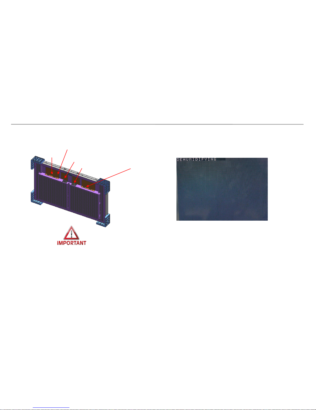
◈ Internal dehumidify pattern :
- After turn on power, press the ‘toggle switch’ button for five(5) seconds.
- dehumidification screen comes out
- There are two ‘toggle swtich’. Please press each one.
3. Preparation for Cabinet Installation
◈ Reference : Process of Dehumidification
16
※ Caution:
1. IWJ (LH008IWJ Doesn’t Power On in STB mode(switch) When you install IWJ, please switch to O mode
2. Do not turn on the white pattern over 10seconds before dehumidification
3. LED defects are prevented by dehumidification, Please dehumidify cabinet before working cabinet
4. Using LSM, dehumidification can be done. Please see ‘8. Settings and How to Use’ Section
POWER INLET
POWER OUTLET
SWITCH
TOGGLE SWITCH
TOGGLE SWITCH

Samsung Electronics
3. Preparation for Cabinet Installation
◈ Reference : Process of Dehumidification
- The Dehumidification process progresses automatically for 24 hours as the brightness increases gradually.
Step condition Brightness Time
1 Lighting up display with 10 gray scale 5% 2 hr
2 Lighting up display with 20 gray scale 8% 2 hr
3 Lighting up display with 30 gray scale 10% 2 hr
4 Lighting up display with 40 gray scale 15% 2 hr
5 Lighting up display with 50 gray scale 20% 2 hr
6 Lighting up display with 70 gray scale 25% 2 hr
7 Lighting up display with 90 gray scale 35% 2 hr
8 Lighting up display with 120 gray scale 45% 2 hr
9 Lighting up display with 150 gray scale 60% 2 hr
10 Lighting up display with 180 gray scale 70% 2 hr
11 Lighting up display with 200 gray scale 80% 2 hr
12 Lighting up display with 255 gray scale 100% 2 hr
Samsung Electronics
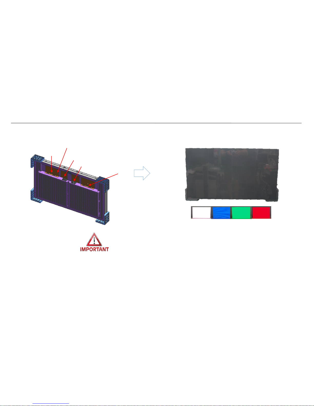
3. Preparation for Cabinet Installation
◈ Reference : Process of Screen check
18
화면 검사 사진 확인
Check the picture of the screen
◈ Internal white pattern
1. After turn on power, press the toggle swtich button for five seconds
2. Dehumidification screen comes out, push the toggle swtich twice
3. when the white screen is displayed, check the defective LED by sequentially pressing toggle switch
* Do not turn on the white pattern over 10 seconds before dehumidification
4. if you need more brighter pattern, push ‘toggle switch’ button for five seconds in white pattern
5. push toggle switch for 5 seconds again to exit factory OSD
POWER INLET
POWER OUTLET
SWITCH
TOGGLE SWITCH
TOGGLE SWITCH

Samsung Electronics
3. Preparation for Cabinet Installation
◈ Reference : Power system design
19
◈ Power system design
1. Power system should be designed according to Screen composition
2. Cabinets that consist same screen (4 for FHD / 8 for UHD) must be powered by same power system.
3. Cabinets that connected to same I/G Board (whether or not it makes FHD/UHD screen) must be powered by
same power system.
▶ S-BOX gives IDs to connected cabinets and it transfer data in order. If the former ID is off while the latter ID is
on, error may occur in data transfer.
I/G #1 I/G #2
I/G #4I/G #3
I/G #1 I/G #2
I/G #4I/G #3
Power 1 Power 2 Power 1 Power 2
Power 3
Samsung Electronics
4. Frame Installation
20
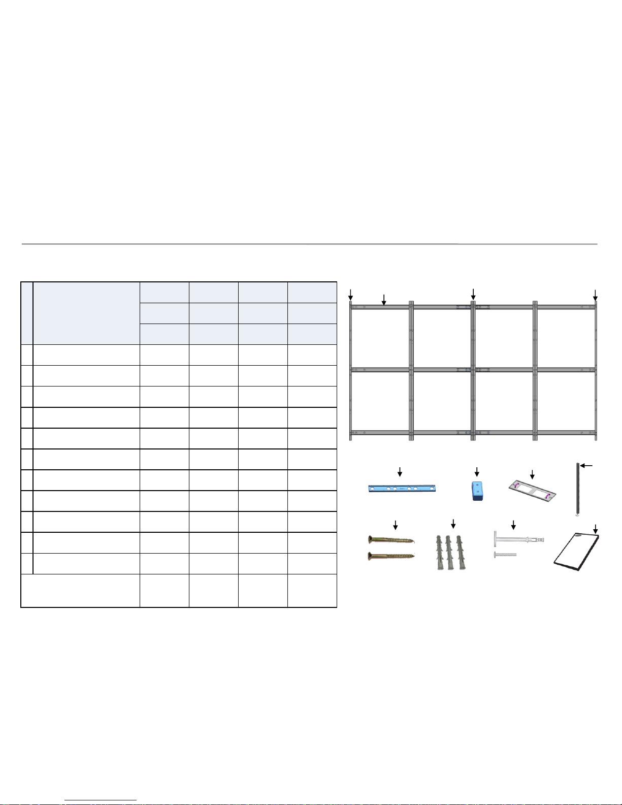
◇ Frame Kit Composition.
No
.
Item
VG-LFJ08SWW
VG-LFJ08FWW
VG-LFJ08TWW
VG-LFJ08UWW
1x1 2x2 3x3 4x4
Units Units Units Units
ⓐ
BRACKET H (horizontal)
2 2 2 6
ⓑ
BRACKET SIDE (vertical)
2 2 2 2
ⓒ
BRACKET
MIDDLE (vertical) - 2 3 4
ⓓ
JOINT H 2 2 2 3
ⓔ
JOINT V 2 4 6 8
ⓕ
BRACKET JIG 1 1 1 1
ⓖ
LEVELER - 2 2 2
ⓗ
SCREW 4 6 6 15
ⓘ
Anchor
4 6 6 15
ⓙ
DRY WALL SCREW
4 6 6 15
ⓚ
MANUAL-INSTALL
1 1 1 1
Size of the Installation
Screen(mm)
806.4x453.6
1612.8x907.2
2419.2*1360.8
3225.6*1814.4
ⓐ
ⓑ
ⓓ
ⓗ
M5,L65
ⓔ
ⓘ
ⓒ
ⓑ
ⓙ
ⓕ
ⓖ
ⓚ
Samsung Electronics
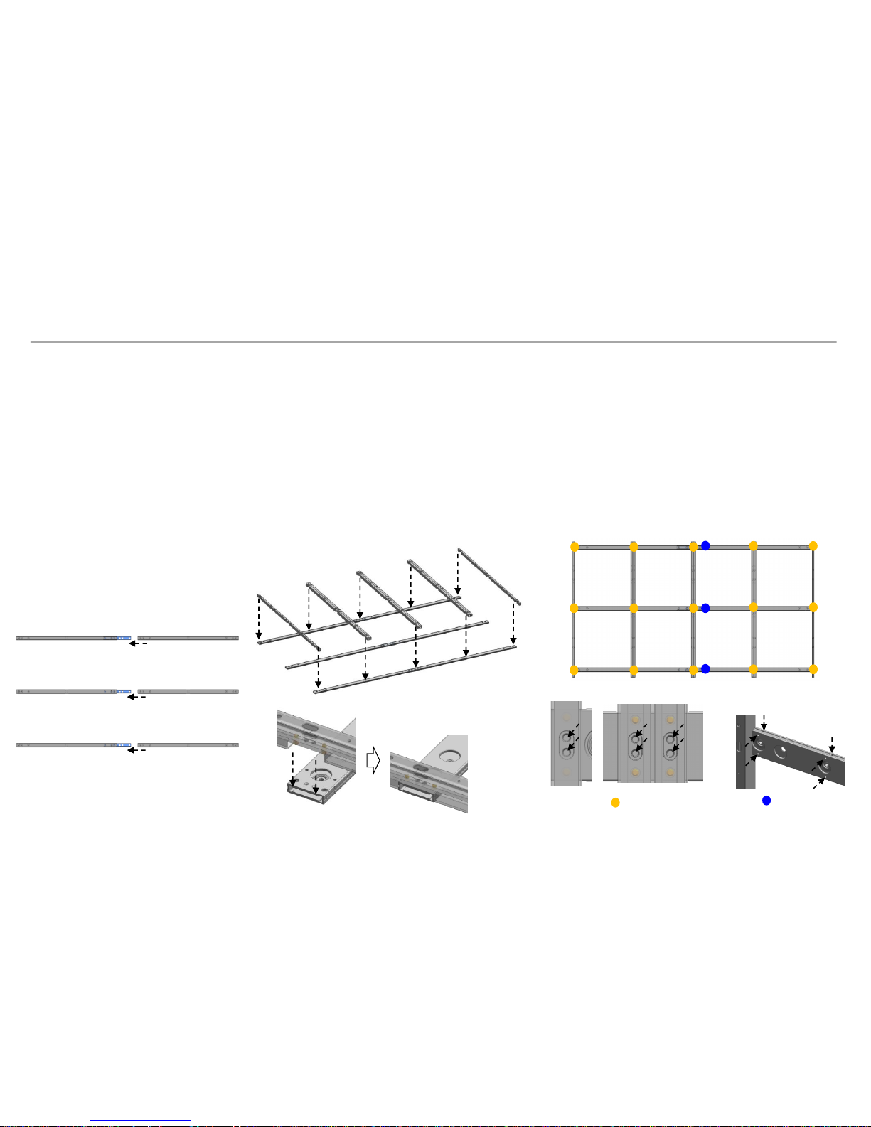
4. Frame Installation
① Assemble Bracket Side/Middle with Bracket H.
- First insert ⓐBracket H to assembled Joint H and Bracket H. (Fig.1)
- Second put 3 groups of Bracket H on ground. And insert Bracket Side/Middle to Bracket H. (Fig.2)
. ⓑ Bracket Side used at side position, ⓒ Bracket Middle used at middle position.
- Then fasten up the screws. (Fig.3)
21
Fig.1 Insert Bracket H
Fig.2 Insert Bracket V to Bracket H
Fig.3 Fix Bracket with screw
M4L8
M6L8
ⓐ
ⓑ,ⓒ
ⓑ
ⓒ
ⓐ
ⓐ

Samsung Electronics
4. Frame Installation
② Assemble Leveler on the Bracket Side at required height position.
- Put Leveler on Bracket side at required height position with moving up and down. (Fig.1)
22
Fig.1 Assemble Leveler
M4 Screw

Samsung Electronics
4. Frame Installation
③ Install assembled Frame on the wall.
- After put assembled Frame on the wall, fasten 1 point at center-top which is closest hole with BRACKET H.
By using Leveler, adjust horizontal level of Frame.
- Place assembled Frame on the wall and measure if there is a height difference among them.
If a height differences is found, adjust Leveling bolt to make same level.
Use a hex wrench(6mm) to adjust height difference of fastening points from wall.(Fig.2)
23
Fig.1 Make horizontal and Fasten 1point Fig.2 Adjust leveling bolt
1Pt Fastening
Adjustment level
Leveling Bolt
Max. +2mm

Samsung Electronics
4. Frame Installation
- Fasten 7 points which are closest hole with Bracket V with using more screws. (Fig.3)
- It may need more fastening screw according to wall condition.
- After fastening, remove the Leveler.
24
Fig.3 Fix Frame with screw
Concrete Wall
Wood Stud Wall
Samsung Electronics
4. Frame Installation
※ Precautions for Fastening the Screws
25

Samsung Electronics
4. Frame Installation
※ Extent Frame Installation to Horizontal / Vertical.
- Assemble Joint C / Joint V into second assembled Frame.
26
<Horizontal Extension>
Fastening
Fastening
<Vertical Extension>
- Insert the second FRAME to first FRAME.
<Vertical Extension>
<Horizontal Extension>

Samsung Electronics
4. Frame Installation
※ Extent Frame Installation to Horizontal
- Mount the Jig by connecting first frame to second frame. And fasten screws.
27
<Vertical Extension>
<Horizontal Extension>
Fastening
Fastening
Samsung Electronics
5. Cabinet + Frame Installation
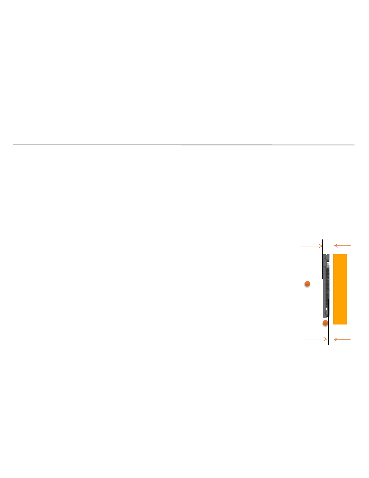
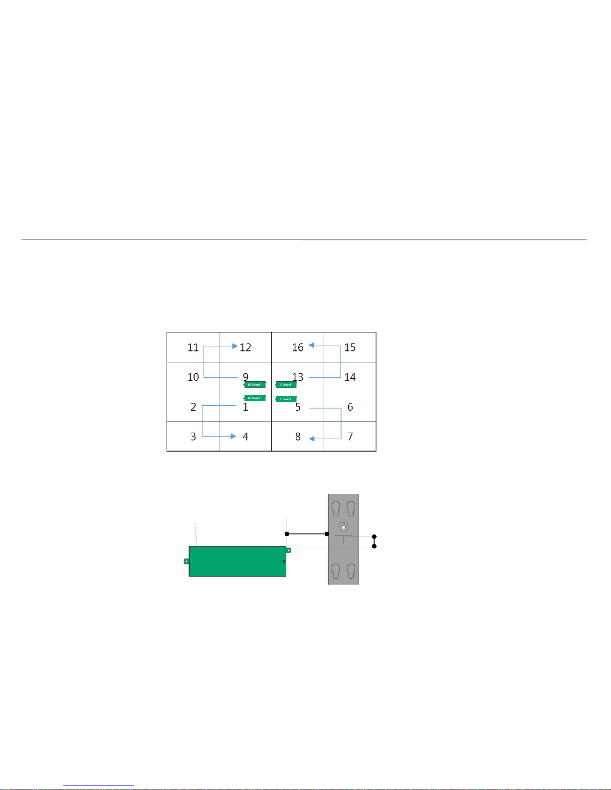
Install I/G first on the back side of the Cabinet of each Type. (Fig.1)
※ Location to Install: Locate the I/G at the point 50~55mm below, which is the standard for carving at the right side of the frame,
and then fasten the screws.(Fig.2)
50~55mm
I/G
• Fix I/G Location
Fig1. Location to Fix the I/G and Order of OCM cable
Fig2. Location to Fix I/G
120~125mm
28
Samsung Electronics
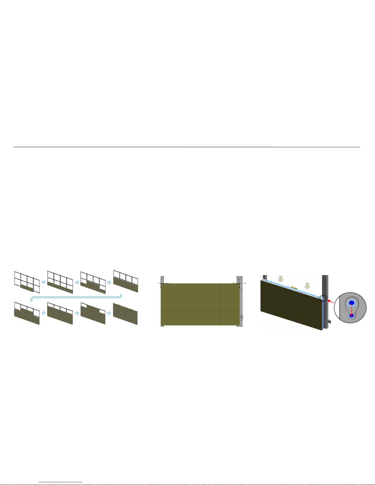
5. Cabinet + Frame Installation
① After installing Frame and I/G, install cabinets on the bottom line first.
※ Refer to the order of installing cabinets. (Bottom to top, Center to side.) (Fig.1)
② Adjust the Corners of the Cabinet to each of the cravings to be closer to the Frame. (Fig.2)
③ Press the upper side of the Frame and assemble so that it slides towards downward. (Fig.3)
• Install main body to Frame
29
Fig.1 Install first cabinet to Frame
Sliding Screw
Fig.2 Adjust the corners to guide line
Guide line
Guide line
Fig.3 Sliding cabinet to Frame
 Loading...