

Samsung 940MW, LDO19CS, LDO19WS, 940MG Service Manual
SERVICE
Manual
LCD Monitor
Fashion Feature
LCD-Monitor
Chassis LDO19WS
LDO19CS
Model 940MW
940MG
- MFM Model
- VCT49xy
- W/W model
- High Contrast Ratio(700:1)
- High Luminance(300cd/m2)

ii
Copyright
©2005 by Samsung Electronics Co., Ltd.
All rights reserved.
This manual may not, in whole or in part, be copied,
photocopied, reproduced, translated, or converted to
any electronic or machine readable form without prior
written permission of Samsung Electronics Co., Ltd.
LDO19WS Service Manual
First edition September 2005.
Printed in Korea.
Trademarks
Samsung is the registered trademark of Samsung
Electronics Co., Ltd.
LDO19WS and MacMaster Cable Adapter are
trademarks of Samsung Electronics Co., Ltd.
Macintosh, Power Macintosh are trademarks of Apple
Computer, Inc.
All other trademarks are the property of their respective
owners.

11. Precautions
………………………………………………………………………………………………………………………………………
11-1
1-1. Safety Precautions ………………………………………………………………………………………………………………………1-1
1-2. Servicing Precautions ……………………………………………………………………………………………………………………1-2
1-3. Static Electricity Precautions ……………………………………………………………………………………………………………1-2
1-4. Install Precautions …………………………………………………………………………………………………………………………1-3
2
2. Product specifications
…………………………………………………………………………………………………………………………
22-1
2-1. Fashion Feature ………………………………………………………………………………………………………………………… 2-1
2-2. Specifications Comparison to the Old Model …………………………………………………………………………………………2-1
2-3. Specifications ………………………………………………………………………………………………………………………………2-2
2-4. Option Specification ………………………………………………………………………………………………………………………2-3
3
3. Alignments and Adjustments
…………………………………………………………………………………………………………………
33-1
3-1. Program Upgrade …………………………………………………………………………………………………………………………3-1
3-2. DDC JIG Installation ……………………………………………………………………………………………………………………3-2
3-3. EDID Installation with Windows Program ………………………………………………………………………………………………3-3
3-4. Factory Mode Adjustments ………………………………………………………………………………………………………………3-4
4
4. Troubleshooting
………………………………………………………………………………………………………………………………
44-1
4-1. No Power
………………………………………………………………………………………………………………………………… 4-1
4-2. No Picture (PC Signal) ………………………………………………………………………………………………………………… 4-2
4-3. No Picture (TV)
…………………………………………………………………………………………………………………………… 4-4
4-4. No Picture (Video/S-Video/Scart)
……………………………………………………………………………………………………… 4-6
4-5. No Picture (Component) ………………………………………………………………………………………………………………… 4-8
4-6. No Sound (TV) ………………………………………………………………………………………………………………………… 4-10
4-7. No Sound (Component) ……………………………………………………………………………………………………………… 4-12
5
5. Exploded View and Parts List
…………………………………………………………………………………………………………………
55-1
6. EElectrical Parts List
……………………………………………………………………………………………………………………………
66-1
7. BBlock Diagram
…………………………………………………………………………………………………………………………………
77-1
8. WWiring Diagram
…………………………………………………………………………………………………………………………………
88-1
9. SSchematic Diagrams
……………………………………………………………………………………………………………………………
99-1
Contents

110. Operating Instructions and Installation
……………………………………………………………………………………………………
110-1
10-1. Front …………………………………………………………………………………………………………………………………… 10-1
10-2. Rear …………………………………………………………………………………………………………………………………… 10-2
10-3. Remote Control ……………………………………………………………………………………………………………………… 10-5
1
11. Disassembly and Reassembly
………………………………………………………………………………………………………………
111-1
11-1. Disassembly …………………………………………………………………………………………………………………………… 11-1
11-3. Reassembly …………………………………………………………………………………………………………………………… 11-3
1
12. PCB Diagram
…………………………………………………………………………………………………………………………………
112-1
13. CCircuit Descriptions
……………………………………………………………………………………………………………………………
113-1
13-1. Block description ……………………………………………………………………………………………………………………… 13-1
1
14. Reference Infomation
…………………………………………………………………………………………………………………………
114-1
14-1. Technical Terms ……………………………………………………………………………………………………………………… 14-1
14-2. Connecting Your Monitor …………………………………………………………………………………………………………… 14-4
14-3. Connecting to Others devices ……………………………………………………………………………………………………… 14-5
14-4. Pin Assignment ……………………………………………………………………………………………………………………… 14-8
14-5. Timing Chart …………………………………………………………………………………………………………………………… 14-9
14-6. Preset Timing Modes ……………………………………………………………………………………………………………… 14-10
14-7. Panel Description …………………………………………………………………………………………………………………… 14-11
Contents

Samsung Electronics Co.,Ltd.
416, Maetan-3Dong, Yeongtong-Gu, Suwon City,
Gyeonggi-Do, Korea, 443-742
Printed in Korea
P/N : BN82-00125C-01
URL : http://itself.sec.samsung.co.kr/
-This Service Manual is a property of Samsung
Electronics Co., Ltd.
Any unauthorized use of Manual can be punished
under applicable International and/or domestic
law.

10 Operating Instructions and Installation
10-1
10 Operating Instructions and Installation
10-1 Front
1. SOURCE
Switches from PC Mode to Video mode.
Changing the source is allowed only in external
devices that are connected to the monitor at the
time.
To switch Screen modes:
[PC] - [DVI] - [TV] - [Ext.] - [AV] - [S-Video] [Component]
2. PIP ( Available in PC/DVI/Component Mode )
In PC Mode, turns on Video or TV screens in PIP
mode.
3. MENU
Use this button for open the on-screen menu and
exits from the menu screen or closes screen
adjustment menu.
4. CH
Moves from one menu item to another vertically or
adjusts selected menu values.
In TV mode, selects TV channels.
5. VOL
Moves from one menu item to another horizontally
or adjusts selected menu values.
Adjusts the audio volume.
6. [ ] Enter button
Activates a highlighted menu item.
7. [ ] Power button
Use this button to turn the monitor on and off.
8. Power indicator
Power Indicator shows PowerSaver mode by
green blinking.
9. Remote Control Sensor
Aim the remote control towards this spot on the
monitor.
10. Speaker
You can hear sound by connecting the soundcard
of your PC to the monitor.
10 Operating Instructions and Installation
10-2
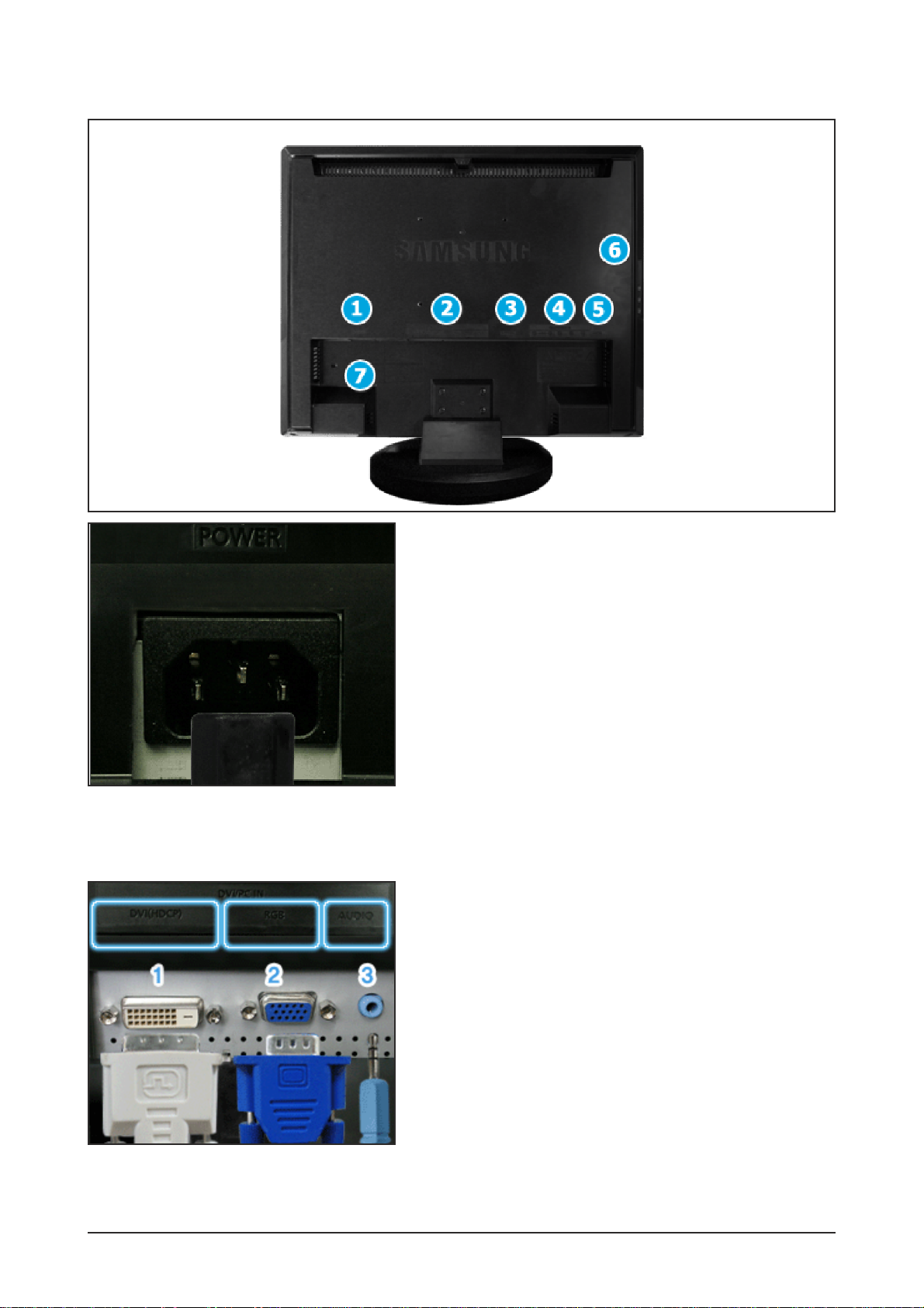
10-2 Rear
1. POWER
Power terminal
Connect the power cord for your monitor to the
POWER on the back of the monitor.
This product may be used with 100 ~ 240VAC
(+/- 10%).
2.DVI/PC IN
1) DVI(HDCP)
: Connect the DVI cable to the DVI(HDCP) port
on the back of your monitor.
2) RGB
: Connect the signal cable to the RGB port on
the back of your monitor.
3) AUDIO
: PC sound terminal (input)

10 Operating Instructions and Installation
10-3
3. EXT(RGB)
External device terminal
EXT(RGB) is mainly used in Europe.
As for EXT(RGB) port of the monitor, it makes TV
or Video signal input and output.
4. COMPONENT IN
1) R - AUDIO - L
: DVD/DTV sound input terminal (left/right)
2) PR, PB,Y
: DVD/DTV video input terminal(PR, PB,Y)
5. ANT IN
TV antenna terminal
10 Operating Instructions and Installation
10-4
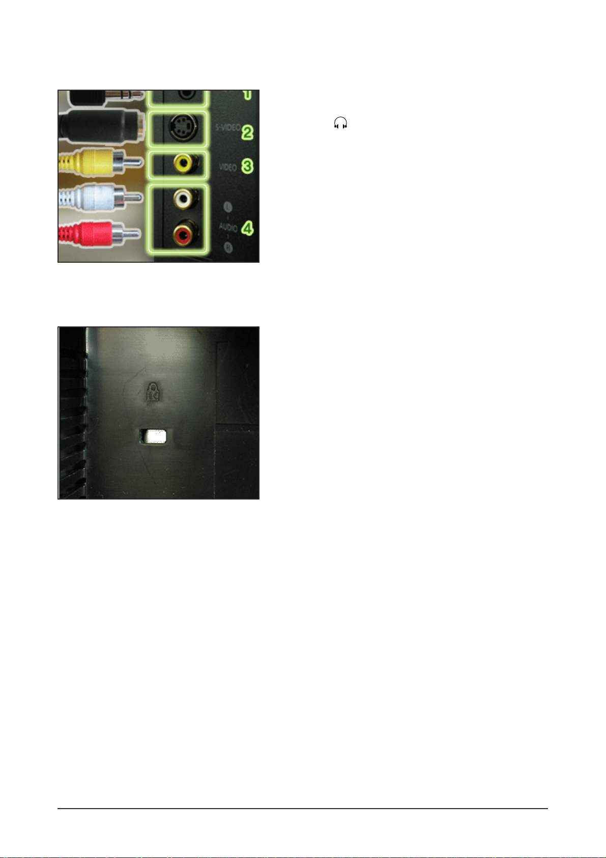
7. Kensington Lock
The Kensington lock is a device used to physically
fix the system when using it in a public place.
(The locking device has to be purchased separately.)
For using a locking device, contact where you
purchase it.
6. AV connection terminal
1)
: Headphone sound output terminal
2) S-VIDEO
: External device (S-video) input terminal
3) VIDEO
: External device (video) input terminal
4) R - AUDIO - L
: External device sound input terminal
10 Operating Instructions and Installation
10-5
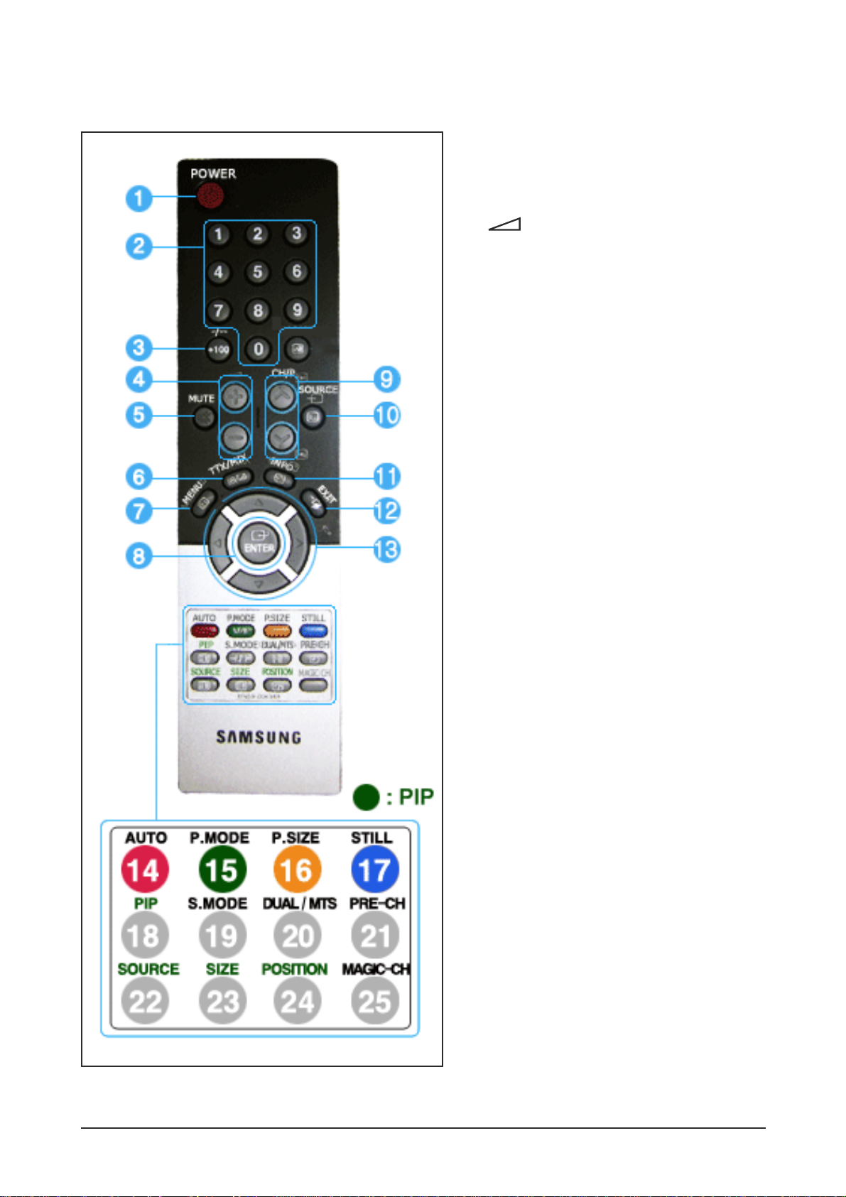
10-3 Remote Control
1. POWER
2. Number button
3. +100, -/--
4. - +
5. MUTE
6. TTX/MIX
7. MENU
8. ENTER
9. CH/P
10. SOURCE
11. INFO
12. EXIT
13. Up-Down Left-Right buttons
14. AUTO
15. P.MODE, M/B (MagicBright¢â)
16. P.SIZE
17. STILL
18. PIP
19. S.MODE
20. DUAL/MTS
21. PRE-CH
22. SOURCE
23. SIZE
24. POSITION
25. MAGIC-CH

1. POWER
Use this button to turn the monitor on and off.
2. Number button
Selects TV channels in the TV mode.
You may use this button in PIP mode as well.
3. +100
Press to select channels over 100.
For example, to select channel 121, press "+100",
then press "2" and "1".
-/-- (One/Two-Digit channel selection )
Use to select a channel numbered ten or over.
Press this button, and the "--" symbol is displayed.
Enter the two-digit channel number.
This function is available only in Europe.
4. - +
Adjusts the audio volume.
5. MUTE
Pauses (mutes) the audio output temporarily.
Displays on the lower left corner of the screen.
The audio resumes if mute or - + is pressed
in the Mute mode.
6. TTX/MIX
TV channels provide written information services
via teletext.
This function is available only in Europe.
7. MENU
Use this button to open the on-screen menu and
exit from the menu screen or close screen
adjustment menu.
8. ENTER
Activates a highlighted menu item.
9. CH/P
In TV mode, selects TV channels.
10. SOURCE
Switches from PC Mode to Video mode.
Changing the source is allowed only in external
devices that are connected to the monitor at the
time.
11. INFO
Current picture information is displayed on the
upper left corner of the screen.
12. EXIT
Exits from the menu screen.
13. Up-Down Left-Right buttons
Moves from one menu item to another horizontally,
vertically or adjusts selected menu values.
14. AUTO - Available in PC Mode Only
Adjusts the screen display automatically.
15. P.MODE, M/B (MagicBright¢â)
When you press this button, current mode is
displayed on the lower center of the screen.
TV / AV / Ext. / S-Video /Component Mode :
P.MODE( Picture Mode )
The monitor has four automatic picture settings
that are preset at the factory.
Then push button again to circle through available
preconfigured modes.
( Dynamic ¡æ Standard ¡æ Movie ¡æ Custom )
PC / DVI Mode : M/B ( MagicBright¢â )
MagicBright¢â is a new feature providing the
optimum viewing environment depending on the
contents of the image you are watching.
Then push button again to circle through available
preconfigured modes.
( Entertain¡æ Internet ¡æ Text ¡æ Custom )
16. P.SIZE - Not available in PC/DVI Mode
Press to change the screen size.
(Auto Wide ¡æ Wide ¡æ Panorama ¡æ Zoom1 ¡æ
Zoom2 ¡æ 4:3)
Panorama, Zoom1, Zoom2 are not available in
1080i(or over 720p) of DTV.
17. STILL - Not available in PC/DVI/Component
Mode
Press the button once to freeze the screen. Press
it again to unfreeze.
18. PIP - Available in PC/DVI/Component Mode
Push the PIP button to turn PIP screen On/Off.
19. S.MODE ( Sound Mode )
When you press this button, current mode is
displayed on the lower center of the screen.
The monitor has a built-in high fidelity stereo
amplifier.
Then push button again to circle through available
preconfigured modes.
(Standard ¡æ Music ¡æ Movie ¡æ Speech ¡æ Custom)
20. DUAL / MTS
DUAL : STEREO/MONO, DUAL l / DUAL ll and
MONO/NICAM MONO/NICAM STEREO can be
operated depending on broadcasting type by using
DUAL button on the remote control while watching
TV.
MTS : You can select the MTS (Multichannel
Television Stereo) mode.
- Mono, Stereo, SAP (Separate Audio Program)
Set 'MTS' to ON to choose Mono, Stereo or SAP.
10 Operating Instructions and Installation
10-6

21. PRE-CH
This button is used to return to the immediately
previous channel.
22. SOURCE - Available in PIP Mode
Selects the Video source.
23. SIZE - Available in PIP Mode
You can switch the PIP picture size.
24. POSITION - Available in PIP Mode
Changes the Position of the PIP window.
25. MAGIC-CH
MagicChannel enables you to watch only certain
channels.
This function is available only in Korea.
10 Operating Instructions and Installation
10-7

Memo
10 Operating Instructions and Installation
10-8
11 Disassembly and Reassembly
11-1
11 Disassembly and Reassembly
This section of the service manual describes the disassembly and reassembly procedures for the
LDO19WS TFT-LCD monitors.
WARNING: This monitor contains electrostatically sensitive devices. Use caution when handling
these components.
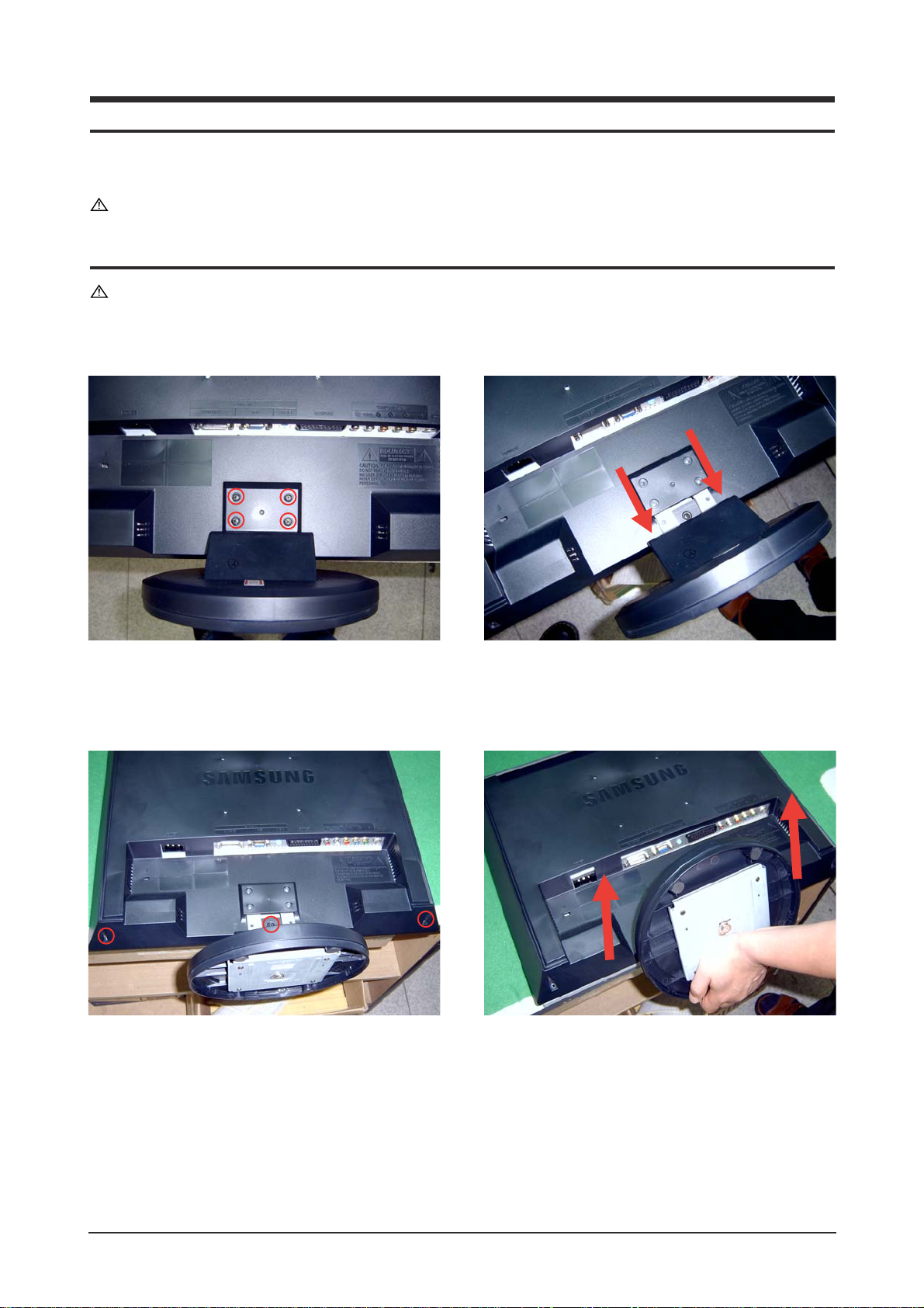
11-1 Disassembly
Cautions: 1. Disconnect the monitor from the power source before disassembly.
2. Follow these directions carefully; never use metal instruments to pry apart the cabinet.
1. Place monitor face down on cushioned table. Remove 4 screws from the stand.
2. Remove 3 screws from the rear-cover. Lift up the rear-cover.

11 Disassembly and Reassembly
11-2
3. Remove 4 screws from the shield-cover.
4. Remove 2 screws from the side connector. Lift up the shield-cover.
5. Remove 9 screws from the boards. Remove 9 screws from the BRKT.

11 Disassembly and Reassembly
11-3
11-2 Reassembly
-Reassembly procedures are in the reverse order of disassembly procedures.
6. Lift up the Panel-BRKT.

Memo
11 Disassembly and Reassembly
11-4
12 PCB Layout
12-1
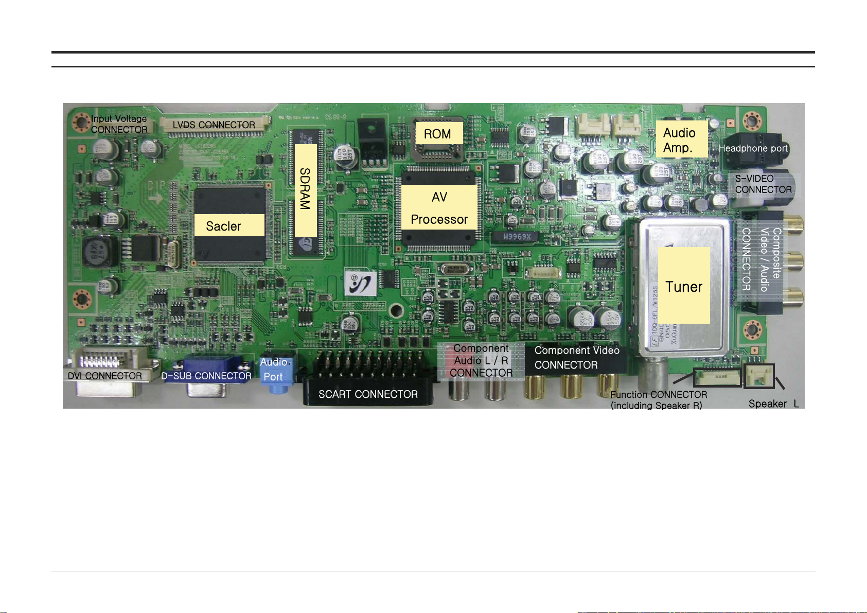
12 PCB Diagram12 PCB Diagram
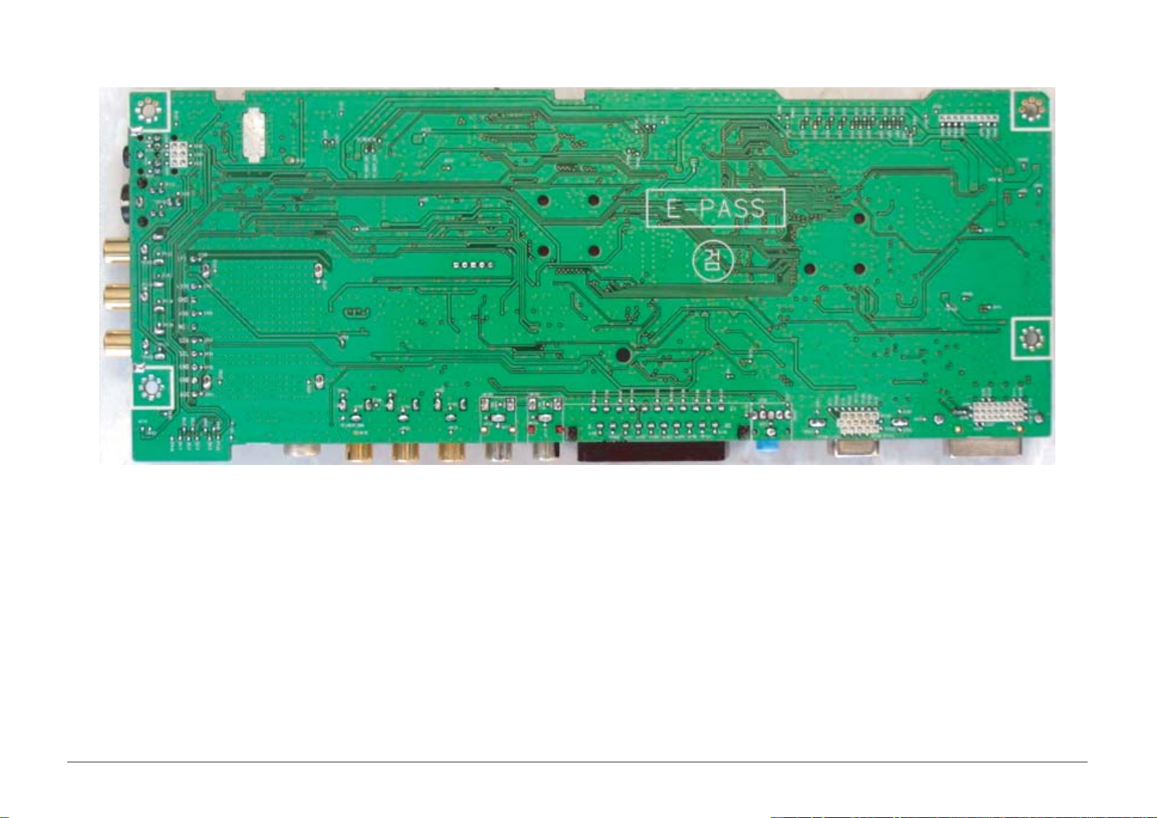
12 PCB Layout
12-2

13 Circuit Descriptions
13-1
13 Circuit Descriptions
13-1 Block description

13 Circuit Descriptions
13-2
13-1-1 VCT49XYI (IC700)
13-1-2 VSP Block
: CVBS, S-Video, RF(IF), SCART
(RGB) Convert 656 format to video
input and transfer to MST51510

13 Circuit Descriptions
13-3
13-1-3 MSP Block
: PC, Sound L/R, SCART,
Receive audio input and send
out to AMP.
13-1-4 SE6181(IC301)
- Scaler(MFM)
- Support Digital Video Input
- Internal LVDS IC
- Support PIP
- OSD controller engine

13 Circuit Descriptions
13-4
13-1-5 Connect a Function Board to a Main Board

- TFT-LCD
(Thin film Transistor Liquid Crystal Display)
ADC(Analog to Digital Converter)
This is a circuit that converts from analog signal to
digital signals.
- PLL(Phase Locked Loop)
During progressing ADC, Device makes clock syn-
chronizing HSYNC with Video clock
- Inverter
Device that supply Power to LCD panel lamp. this
device gernerate about 1,500~2,000V.
- AC Adapter
Device that converts AC(90V~240V) to DC(+12V
or 14V)
- SMPS(Switching Mode Power Supply)
Switching Mode Power supply. This design tech-
nology is used to step up/down the input power by
switching on/off
- FRC(Frame Rate Controller)
Technology that change image frame quantity dis-
played on screen for one second.
Actually TFT-LCD panel require 60 pcs of frame
for one second.
so,this technology is needed to convert input
image to 60 pcs regardless input frame quantity.
- Image Scaler
Technology that convert various input resolution to
other resolution.(ex. 640* 480 to 1024*768)
- Auto Configuration(Auto adjustment)
This is an algorithm to adjust monitor to optimum
condition by pushing one key.
- OSD(On Screen Display)
On screen display. customer can control the
screen easily with this.
- Image Lock
This means "Fineness adjustment " in LCD
Monitor, the features are "Fine" and "Coarse"
- FINE
"Fine" adjustment is used to adjust visibility by
control phase difference.
- COARSE
This is a adjustment by tuning with Video colck
and PLL clock.
- DVI (Digital Visual Interface)
This provides a high speed digital connection for
visual data types that is display technology inde-
pendent. this interface is primarily forcused at pro-
viding a connection between a computer and
its display device.
- L.V.D.S.(Low Voltage Differential Signaling)
a kind of transmission method for Digital.It can be
used from Main PBA to Panel.
- T.M.D.S
(Transition minimized Differential Signaling)
a kind of transmission method for Digital.
It can be used from Video card to Main PBA.
- DDC(Display data channel)
It is a communication method between Host
Computer and related equipment.
It can make it Plug and Play between PC and
Monitor.
- EDID
Extended Display Identification Data PC can rec-
ognize the monitor information as Product data,
Product name,Display mode,Serial number and
Signal source,etc through DDC Line communicat-
ing with PC and Monitor.
14 Reference Infomation
14-1
14 Reference Infomation
14-1 Technical Terms

14 Reference Infomation
14-2
- Dot Pitch
The image on a monitor is composed of red, green
and blue dots. The closer the dots, the higher the
resolution. The distance between two dots of the
same color is called the 'Dot Pitch'. Unit: mm
- Vertical Frequency
The screen must be redrawn several times per
second in order to create and display an image for
the user. The frequency of this repetition per second is called Vertical Frequency or Refresh Rate.
Unit: Hz
Example: If the same light repeats itself 60 times
per second, this is regarded as 60 Hz.
- Horizontal Frequency
The time to scan one line connecting the right
edge to the left edge of the screen horizontally is
called Horizontal Cycle. The inverse number of the
Horizontal Cycle is called Horizontal Frequency.
Unit: kHz
- Interlace and Non-Interlace Methods
Showing the horizontal lines of the screen from the
top to the bottom in order is called the NonInterlace method while showing odd lines and then
even lines in turn is called the Interlace method.
The Non-Interlace method is used for the majority
of monitors to ensure a clear image. The Interlace
method is the same as that used in TVs.
- Plug & Play
This is a function that provides the best quality
screen for the user by allowing the computer and
the monitor to exchange information automatically.
This monitor follows the international standard
VESA DDC for the Plug & Play function.
- Resolution
The number of horizontal and vertical dots used to
compose the screen image is called 'resolution'.
This number shows the accuracy of the display.
High resolution is good for performing multiple
tasks as more image information can be shown on
the screen.
Example: If the resolution is 1280 x 1024 , this
means the screen is composed of 1280 horizontal
dots (horizontal resolution) and 1024 vertical lines
(vertical resolution).
- DVD
A type of digital disk technology that takes up only
the benefits of CD and LD, to implement a high
resolution/quality, which enables the user to enjoy
clearer images.
- DTV
Broadcasting (Digital TV Broadcasting)
An enhanced broadcasting technology to process
digital video signals using a set-top box, which
implements a high resolution and clearer digital
images on the screen.
- A2
This system uses two carriers to transmit voice
data. Countries such as South Korea and
Germany use this system.
- BTSC
Broadcast Television System Committee
The stereo broadcasting system that is used in
most of the countries that have adopted the NTSC
system, including the United States, Canada,
Chile, Venezuela and Taiwan. It also refers to the
organization that has been organized to promote
its development and management.
- EIAJ
Electronic Industries Association of Japan.
- RF Cable
A round signal cable generally used for TV antennas.
- Satellite Broadcasting
Broadcasting service provided via satellite.
Enables high picture quality and clear sound
throughout the country regardless of the location of
the viewer.
- Sound Balance
Balances the levels of the sound coming from
each speaker in televisions with two speakers.
- Cable TV
Whereas the terrestrial broadcasting is delivered
via frequency signals through the air, cable broadcasting is transmitted via a cable network. In order
to view cable TV, one must purchase a cable
receiver and hook it up to the cable network.
- CATV
"CATV" refers to the broadcasting service offered
at hotels, schools and other buildings through their
own broadcasting system, apart from VHF or UHF
broadcasting by terrestrial broadcasters. The
CATV programs may include movies, entertainment and educational programs. (Different from
cable TV.)
CATV can be viewed only within the area in which
the CATV service is offered.
- S-Video
Short for "Super Video." S-Video allows up to 800
lines of horizontal resolution, enabling high-quality
video.

- VHF/UHF
VHF indicates TV channels 2 to 13, and UHF indi-
cates channels 14 through 69.
- Channel Fine Tuning
This feature allows the viewer to fine-tune the TV
channel to obtain the best viewing conditions. The
Samsung LCD TV has both automatic and manual
channel fine-tuning features to enable the viewer
to adjust their desired settings.
- External Device Input
External device input refers to video input from
such external video device as VCR, camcorder
and DVD player, separate from a TV broadcast.
- LNA (Low Noise Amplifier)
This derives from artificial satellite technology that
amplifies weak signals even in poor reception
areas for sharper images.
- Antenna Converter
A connection part that is used to link a wide
antenna cable (feeder cable) to the TV.
- English Caption (= Caption Setting)
A kind of language selection feature that provides
English subtitles (caption) or character information
services from broadcasting services (ex: AFKN) or
video tapes (marked CC), and which are especially
useful for studying English.
14 Reference Infomation
14-3
14 Reference Infomation
14-4
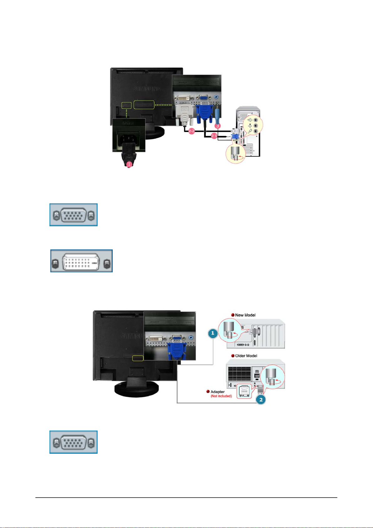
14-2 Connecting the Monitor
1. Connect the power cord for your monitor to the POWER on the back of the monitor.
Plug the power cord for the monitor into a nearby outlet.
2-1. Using the D-sub (Analog) connector on the video card.
Connect the signal cable to the 15-pin, RGB port on the back of your monitor.
2-2. Using the DVI (Digital) connector on the video card.
Connect the DVI Cable to the DVI Port on the back of your Monitor.
3. Connect the audio cable for your monitor to the audio port on the back of your computer.
4. Turn on both your computer and the monitor.
1. Using the D-sub (Analog) connector on the video card.
Connect the signal cable to the D-SUB port on the Macintosh computer.
2. For older model Macintoshes, you need to adjust the resolution control DIP switch on the Macintosh
adapter (optional) referring to the switch configuration table shown on its rear.
3. Turn on the monitor and Macintosh.
- Connecting to a monitor
-Connecting to a Macintosh

14 Reference Infomation
14-5
14-3 Connecting to Other devices
1. Input devices such as DVD, VCR or Camcorder are connected to the VIDEO or S-VIDEO terminal of
the monitor using the Video or S-Video cable.
*
S-Video, Video cable and EXT(RGB) cable is optional.
2. Connect the Audio (R) and Audio (L) terminals of a DVD, VCR or Camcorders to the monitor's R and L
audio input terminals using audio cables.
3. Then, start the DVD, VCR or Camcorders with a DVD disc or tape inserted.
4. Select AV or S-Video using the SOURCE.
- Connecting AV Devices
1. Connect a video cable between the EXT(RGB) jacks on the monitor and the EXT(RGB) jacks on the
DVD Player.
2. Select Ext. using the SOURCE.
-
Connecting EXT.(RGB) - It only applies to AV DEVICE that supports SCART.

14 Reference Infomation
14-6
1. Connect the CATV or antenna coaxial cable to the Antenna terminal on the rear of the monitor.
You need to use a coaxial antenna cable.
- When using an interior antenna terminal:
Check the antenna terminal on the wall first and connect the antenna cable.
- When using an outdoor antenna:
If you are using an outdoor antenna, use a professional for installation if possible.
- To connect the RF cable to the antenna input terminal:
Keep the copper wire portion of the RF cable straight.
2. Turn on the monitor.
3. Select TV using SOURCE button among the external signal adjustment buttons.
4. Select a desired TV channel.
- Connecting TV
1. Connect the Audio (R) and Audio (L) outputs on the DVD / DTV set top box to the Audio (R) and Audio
(L) inputs on the monitor using audio cables.
2. Connect a video cable between the component( P
R, PB,Y) jacks on the monitor and the PR, PB,Y
jacks on the DVD / DTV set top box.
3. Select Component using the SOURCE.
- Connecting DVD/DTV Set Top Box
14 Reference Infomation
14-7
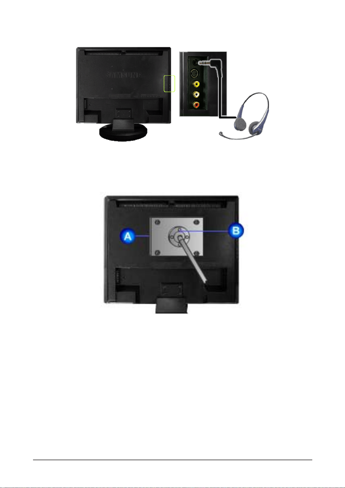
1. Connect your headphones to the Headphone connection terminal.
- Connecting Headphone
A. Monitor
B. Mounting interface pad (Sold separately)
1. Turn off your monitor and unplug its power cord.
2. Lay the LCD monitor face-down on a flat surface with a cushion beneath it to protect the screen.
3. Remove four screws and then remove the Stand from the LCD monitor.
4. Align the Mounting Interface Pad with the holes in the Rear Cover Mounting Pad and secure it with four
screws that came with the arm-type base, wall mount hanger or other base.
*
This monitor accepts a 100 mm x 100 mm VESA-compliant mounting interface pad.
-Attaching a Base
 Loading...