

Samsung LA32S81B Schematic
TFT-LCD TV
Chassis GJA32SSA
GJA37SSA
GJA40SSA
GJA46ASA
Model LA32S81B
LA37S81B
LA40S81B
LA46S81B
Manual
SERVICE
TFT-LCD TV Fashion Feature
- Luxurious Slim Design
- Supreme Picture Quality
- Supreme Sound Quality
- Supreme Convenience Quality
- Convenience for Users

ii
Copyright
ⓒ 2007 by Samsung Electronics Co., Ltd.
All rights reserved.
This manual may not, in whole or in part, be copied,
photocopied, reproduced, translated, or converted to any
electronic or machine readable form without prior
written permission of Samsung Electronics Co., Ltd.
LA32S81B/LA37S81B/LA40S81B/LA46S81B
Service Manual
First edition June 2007.
Printed in Korea.
Trademarks
Samsung is the registered trademark of Samsung
Electronics Co., Ltd.
LA32S81B/LA37S81B/LA40S81B/LA46S81B and
Macmaster Cable Adapter are trademarks of Samsung
Electronics Co., Ltd.
Macintosh and Power Macintosh are trademarks of
Apple Computer, Inc.
All other trademarks are the property of their respective
owners.

Contents
11. Precautions
………………………………………………………………………………………………………………………………………
11-1
1-1 Safety Precautions ……………………………………………………………………………………………………………………… 1-1
1-2 Servicing Precautions …………………………………………………………………………………………………………………… 1-2
1-3 Static Electricity Precautions …………………………………………………………………………………………………………… 1-2
1-4 Installation Precautions…………………………………………………………………………………………………………………… 1-3
2
2. Product specifications
…………………………………………………………………………………………………………………………
22-1
2-1 Fashion Feature…………………………………………………………………………………………………………………………… 2-1
2-2 LA32S81B Specifications ………………………………………………………………………………………………………………… 2-2
2-3 LA37S81B Specifications ………………………………………………………………………………………………………………… 2-3
2-4 LA32S81B Specifications ………………………………………………………………………………………………………………… 2-4
2-5 LA46S81B Specifications ………………………………………………………………………………………………………………… 2-5
2-5 Spec Comparison ………………………………………………………………………………………………………………………… 2-6
2-6 Option Specification ……………………………………………………………………………………………………………………… 2-7
3
3. Alignments and Adjustments
…………………………………………………………………………………………………………………
33-1
3-1 Service Instruction ……………………………………………………………………………………………………………………… 3-1
3-2 How to Access Service Mode …………………………………………………………………………………………………………… 3-2
3-3 Factory Data ……………………………………………………………………………………………………………………………… 3-3
3-4 Service Adjustment ……………………………………………………………………………………………………………………… 3-12
3-5 Software Upgrade ……………………………………………………………………………………………………………………… 3-15
4
4. Troubleshooting
………………………………………………………………………………………………………………………………
44-1
4-1 First Checklist for Troubleshooting ………………………………………………………………………………………………………4-1
4-2 Checkpoints by Error Mode ……………………………………………………………………………………………………………… 4-2
5
5. Exploded View and Parts List
…………………………………………………………………………………………………………………
55-1
5-1 LA32S81B Exploded View ……………………………………………………………………………………………………………… 5-1
5-2 LA32S81B Parts list ……………………………………………………………………………………………………………………… 5-2
5-3 LA37S81B Exploded View ……………………………………………………………………………………………………………… 5-3
5-4 LA37S81B Parts list ……………………………………………………………………………………………………………………… 5-4
5-5 LA40S81B Exploded View ……………………………………………………………………………………………………………… 5-5
5-6 LA40S81B Parts list ……………………………………………………………………………………………………………………… 5-6
5-7 LA46S81B Exploded View ……………………………………………………………………………………………………………… 5-7
5-8 LA46S81B Parts list ……………………………………………………………………………………………………………………… 5-8
6
6. Electrical Parts List
……………………………………………………………………………………………………………………………
66-1
6-1 LA32S81B Parts List ……………………………………………………………………………………………………………………… 6-1
6-2 LA37S81B Parts List …………………………………………………………………………………………………………………… 6-20
6-3 LA40S81B Parts List …………………………………………………………………………………………………………………… 6-35
6-4 LA46S81B Parts List …………………………………………………………………………………………………………………… 6-35
7
7. Block Diagram
…………………………………………………………………………………………………………………………………
77-1

Contents
88. Wiring Diagram
…………………………………………………………………………………………………………………………………
88-1
8-1 Wiring Diagram ……………………………………………………………………………………………………………………………8-1
8-2 Main Board Layout ……………………………………………………………………………………………………………………… 8-2
8-3 PIN characteristic ………………………………………………………………………………………………………………………… 8-3
8-4 Power Board Layout ……………………………………………………………………………………………………………………… 8-6
99. Schematic Diagrams
……………………………………………………………………………………………………………………………
99-1
10. O
Operating Instructions and Installation
………………………………………………………………………………………………………
110-1
10-1 Front …………………………………………………………………………………………………………………………………… 10-1
10-2 Connection Panel ……………………………………………………………………………………………………………………… 10-2
10-3 Remote control ………………………………………………………………………………………………………………………… 10-4
10-4 Installing the Stand …………………………………………………………………………………………………………………… 10-5
10-5 Installing the Wall Mount Kit ………………………………………………………………………………………………………… 10-5
1
11. Disassembly and Reassembly
………………………………………………………………………………………………………………
111-1
11-1 Disassembly …………………………………………………………………………………………………………………………… 11-1
11-2 Reassembly …………………………………………………………………………………………………………………………… 11-5
1
12. PCB Diagram
…………………………………………………………………………………………………………………………………
112-1
13. CCircuit Descriptions
……………………………………………………………………………………………………………………………
113-1
13-1 Block description ……………………………………………………………………………………………………………………… 13-1
13-2 Main Block ……………………………………………………………………………………………………………………………… 13-3
13-3 SMPS Board …………………………………………………………………………………………………………………………… 13-4
1
14. Reference Infomation
………………………………………………………………………………………………………………………
114-1
14-1 Technical Terms ……………………………………………………………………………………………………………………… 14-1
14-2 Pin Assignments ……………………………………………………………………………………………………………………… 14-4
14-3 Timing Chart …………………………………………………………………………………………………………………………… 14-7
14-4 Panel Description …………………………………………………………………………………………………………………… 14-11

Samsung Electronics Co.,Ltd.
416, Maetan-3Dong, Yeongtong-Gu, Suwon City,
Gyeonggi-Do, Korea, 443-742
Printed in Korea
P/N : BN82-00202A-00
URL : http://itself.sec.samsung.co.kr/
- This Service Manual is a property of
Samsung Electronics Co., Ltd.
Any unauthorized use of Manual can be
punished under applicable International
and/or domestic law.

3 Alignments and Adjustments
3-1
3 Alignments and Adjustments
3-1 Ser vice Instr uction
1. Usually, a color TV-VCR needs only slight touch-up adjustment upon installation.
Check the basic characteristics such as height, horizontal and vertical sync.
2. Use the specified test equipment or its equivalent.
3. Correct impedance matching is essential.
4. Avoid overload. Excessive signal from a sweep generator might overload the front-end
of the TV. When inserting signal markers, do not allow the marker generator to distort
test result.
5. Connect the TV only to an AC power source with voltage and frequency as specified on
the backcover nameplate.
6. Do not attempt to connect or disconnect any wire while the TV is turned on. Make sure
that the power cord is disconnected before replacing any parts.
7. To protect aganist shock hazard, use an isolation transform.
3 Alignments and Adjustments
3-2
3-2 How to Access Service Mode
3-2-1 Entering Factory Mode
1. To enter "Service Mode" Press the remote -control keys in this sequence :
- If you do not have Factory remote - control
- If you have Factory remote - control
- The buttons are active in the service mode.
1. Remote - Control Key : Power, Arrow Up, Arrow Down, Arrow Left
Arrow Right, Menu, Enter, Number Key(0~9)
2. Function - Control Key : Power, CH +, CH -, VOL +, VOL -, Menu, TV/VIDEO(Enter)
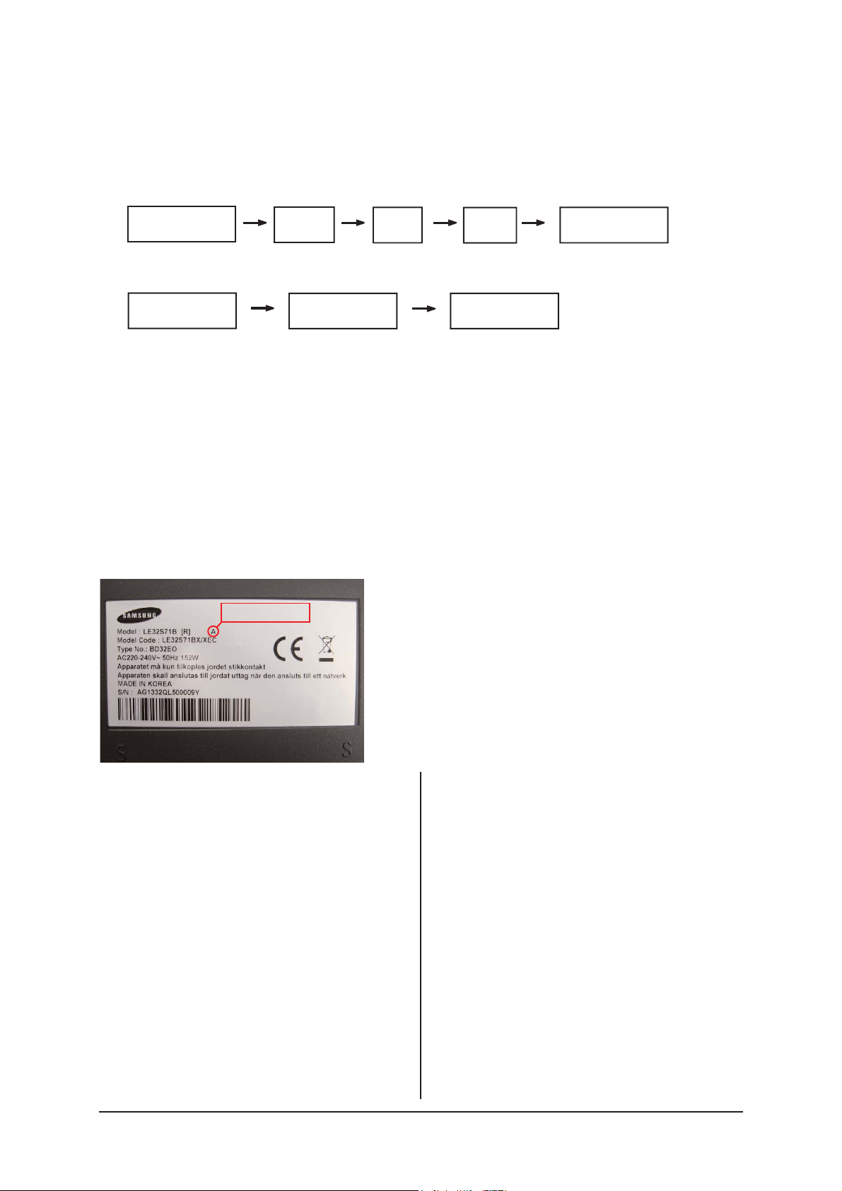
3-2-2 Panel Check
Specially for LE26,32R7**, You have to check Panel Maker Because of different adjustments as follows.
First of all, Check the label rating!
1) Label Rating File
If Panel Mark is "A", Set the factory mode
indicating as follows.
Panel BOM(Bill of material) : BN07-00289A
Connector between Panel and Power Unit
: BN39-00603M (300mm)
* Option Byte
1. Gamma "AUO"
2. Panel Option "AUO"
If Panel Mark is "S" or not printed.
Set the factory mode indicating as follows.
Panel BOM(Bill of material) : BN07-00247A
Connector between Panel and Power Unit
: BN39-00603M (300mm)
* Option Byte
1. Gamma "AMLCD"
2. Panel Option "AMLCD_INT"
If Panel Mark is "C" , Set the Factory mode
indicating as follows.
Panel BOM(Bill of Material) : BN07-00207A
Connecotor between Panel and Powe Unit :
BN39-00659A(200mm)
* Option Byte
1. Gamma " CMO "
2. Panel Option " CMO "
Others are same shown below.
PANEL MAKER
Power OFF
PICTURE ON
INFO
DISPLAY
MENU
MUTE
FACTORY
Power ON

3 Alignments and Adjustments
3-3
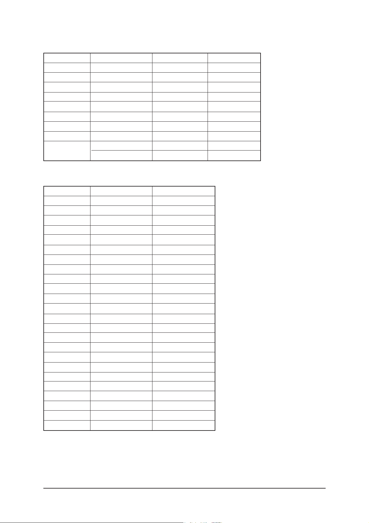
3-3 Factory Data
1. Calibration
2. Option Table XXXX XXXX
3. W/B
4. W/B Movie
5. MTK8202
6. FBE2 option
7. Sound
8. Sound AMP
9. YC Delay
10. Adjust
11. Bus Stop
12. Password 80 80 80 80
13. Checksum 0000
14. Dynamic Contrast
15. Spread Spectrum
16. Reset
HDCP Write Success..(or Failure..)
T_JSMMPEU-1000 (Main Micom Ver) Month/ Day / Year / Hour/ Min./Sec.
T-BRPMNSAS-1000 (Sub Micom Ver. Only BDX Plus)
Panel On Time(Hour) XXXXX
1. Calibration
1) AV Calibration
2) DTV Calibration
3) PC Calibration
4) HDMI Calibration
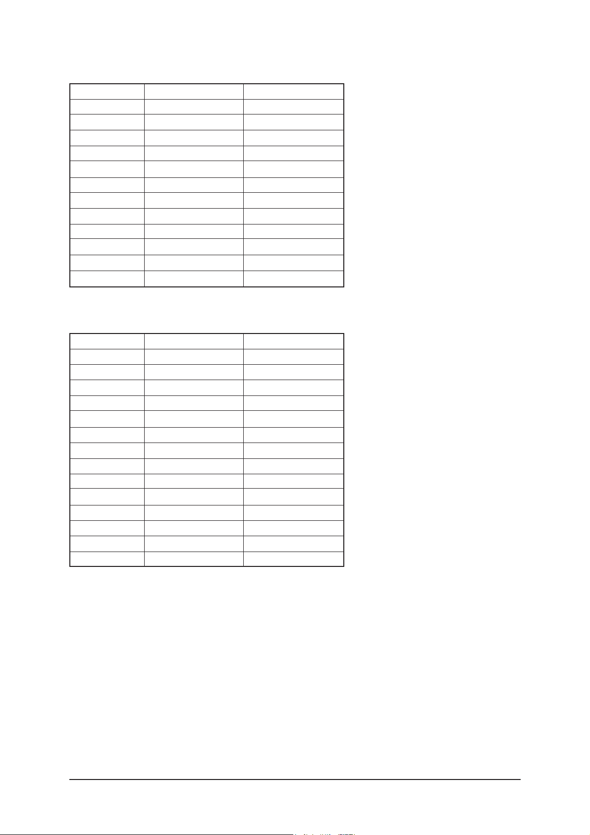
2. Option Byte
NO
1
2
3
4
5
6
7
8
9
10
11
12
13
14
15
16
17
18
19
item
Panel Inch
Panel Vender
Dimming
Gamma
Auto Power
Hotel Mode
Shop Mode
High Devi
Carrier Mute
TTX
TTX List
TTX Group
TTX ATM
HDMI Select
Volume Table
Sound Wattage
HP Position
Language
HP Detect
CMO 32"
32
CMO
INTERNAL
Off
On
Off
Off
Off
Off
On
Flof
User OSD
Off
2HDMI
Small
LCD 10W
Side
English
Active High
3 Alignments and Adjustments
3-4
3. White Balance
No
1
2
3
4
5
6
7
8
»ç¾ç
item
SubBright
Roffset
Goffset
Boffset
SubContrast
RGain
GGain
BGain
Low Light
High Light
RF/AV Component
4. W/B Movie
NO
1
2
3
4
5
6
7
8
9
10
11
12
13
14
15
16
17
18
19
20
21
22
23
24
item
Service P Mode
Service Color Tone
MSub Brightness
MSub Contrast
Warm1 Red Gain
Warm1 Blue Gain
Warm1 Red Offset
Warm1 Blue Offset
Warm2 Red Gain
Warm2 Blue Gain
Warm2 Red Offset
Warm2 Blue Offset
Normal Red Gain
Normal Blue Gain
Normal Red Offset
Normal Blue Offset
Cool2 Red Gain
Cool2 Blue Gain
Cool2 Red Offset
Cool2 Blue Offset
Mov. Contrast
Mov. Brightness
Mov. Color
Mov. Sharpness
RF/AV/S_video
Dynamic
Cool1
128
128
143
111
128
127
142
101
127
128
134
121
127
126
128
134
128
128
80
50
25
45

3 Alignments and Adjustments
3-5
5. MTK8202
1) Cal. Adjustment
2) Cal. Target
NO
1
2
3
4
5
6
7
8
9
10
11
12
13
14
15
16
17
18
19
20
21
22
23
24
25
item
R_Offset
G_Offset
B_Offset
R_Gain
G_Gain
B_Gain
Y_Offset
Cb_Offset
Cr_Offset
Y_Gain
Cb_Gain
Cr_Gain
CVBS Offset
CVBS Gain
CVBS U
CVBS V
HDMI R_Gain Ref.
HDMI G_Gain Ref.
HDMI B_Gain Ref.
HDMI R_Offset Ref.
HDMI G_Offset Ref.
HDMI B_Offset Ref.
2nd Cal Error AV
2nd Cal Error DTV
LVDS Control
value
30
32
23
77
85
89
21
39
41
41
41
41
55
52
0
0
229
229
229
16
16
16
2
2
55
NO
1
2
item
Black Target
White Target
value
1
235
3) Scart RGB
NO
1
2
3
4
5
6
item
SC1_R_Offset
SC1_G_Offset
SC1_B_Offset
SC1_R_Gain
SC1_G_Gain
SC1_B_Gain
ALL Mode
115
115
115
70
70
70
3 Alignments and Adjustments
3-6
4) Picture enhance 1
NO
1
2
3
4
5
6
7
8
9
10
11
12
item
Dynamic Contrast
Dynamic CE
Dynamic Dimming
Black_Min
Black_Middle
Black_Max
Cut Off
Upper
Center L Lmt
Center R Lmt
Ugain Max
Lgain Max
value
on
on
on
14
26
36
4
28
6
26
16
8
5) Picture enhance 2
NO
1
2
3
4
5
6
7
8
9
10
11
12
13
14
item
PreLGain_Main
PreMGain_Main
PreHGain_Main
PreLGain_Sub
PreMGain_Sub
PreHGain_Sub
LocalLGain
LocalMGain
LocalHGain
PostLGain
PostMGain
PostHGain
Vgain
Sub Color
value
64
64
64
64
64
64
72
80
64
72
72
84
0
28
3 Alignments and Adjustments
3-7
6) FBE2 option
NO
1
2
3
4
5
6
7
8
9
10
11
12
13
14
15
16
17
18
19
20
21
22
23
item
Patt-Sel
B-Slope gain
B-Tilt min
B-Tilt max
B-Tilt slpe
Lfunc-Basis
Hfunc-Basis
Mean-Offset1
Mean-Offset2
Mean-Slope
Input-Offset
Input-gain
ACR-Offset
ACR-Th1
ACR-Th2
Skin-Enable
Skin-Tu
Skin-Tv
M-Skin-Tu
M-Skin-Tv
Sub color
M-Au-Sub color
M-Wi-Sub color
value
0
64
20
120
128
75
88
75
150
41
128
128
30
30
100
On
22
22
128
128
143
128
128

3 Alignments and Adjustments
3-8
7) Sound
NO
1
2
3
4
5
6
7
8
9
10
11
12
13
14
15
16
17
18
19
20
21
22
23
24
25
26
item
AM Mute
AM_mute Th_High
AM_mute Th_Low
FM Mute
FM_mute Th_High
FM_mute Th_Low
Correct Threshold
Sync Loop
Error Threshold
Parity Error Thrd
Every Num Frames
Num of Check
Num of Double Chk
Mono Weight
Stereo Weight
Dual Weight
M2S Threshold
S2M Threshold
NICAM FINE VOL
FM FINE VOL
AM FINE VOL
FINE TUNE VOL
SC1 Fine Vol
SC2 Fine Vol
Output Matrix
Speaker EQ
value
Off
9
8
Off
34
32
6
201
8
48
512
10
10
1
1
1
10
10
20
20
19
20
21
21
Bypass
Off
8) SOUND AMP
1
2
Amp Volume
Speaker EQ
17
OFF
3 Alignments and Adjustments
3-9
9) YC Delay
NO
1
2
3
4
5
6
7
8
9
10
11
12
13
14
15
item
RF PAL-B/G
RF PAL-D/K
RF PAL- I
RF PAL- L/L'
RF SECAM-B/G
RF SECAM-D/K
RF SECAM-I
RF SECAM-L/L'
RF NTSC3.58
RF NTSC4.43
AV PAL
AV SECAM
AV NTSC 3.58
AV NTSC4.43
AV PAL60
TV/AV/S_Video
6
5
5
5
7
5
5
5
5
6
3
7
6
6
5
9. Adjust
NO
1
2
3
4
5
6
7
8
9
10
11
12
13
14
15
16
item
TTX PWM
Dyn. Contrast
Dyn. Brightness
Dyn. Color
Dyn. Sharpness
Std. Contrast
Std. Brightness
Std. Color
Std. Sharpness
Melody Volume
Brightness Center
Contrast Gain
MTK_Dyn.Contrast
DSP Recovery
Channel Table
Video Mute Time
value
30
100
45
55
75
80
50
55
50
20
38
64
On
Off
Suwon
10
1) User Control Initial

3 Alignments and Adjustments
3-10
NO
1
2
3
4
5
6
7
8
9
item
LNA Plus
RF_dB0_TH
RF_dB1_TH
RF_dB2_TH
RF_dB3_TH
NR1_Coring
NR2_Coring
NR3_Coring
NR4_Coring
value
On
5
15
43
64
16
32
32
32
2) LNA PLUS
NO
1
2
3
4
5
6
item
Power On Channel
Power On Band
Power On Volume
Max Volume
Local Key Lock
Power On Source
value
1
Air
10
100
OFF
TV
3) Hotel Option
NO
1
2
3
4
5
item
Main Loop
Eeprom
Tuner
Normal
Watch Dog
value
Off
Off
Off
Off
On
10. Bus Stop
11. Password : 80 80 80 80
12. Checksum XXXX

3 Alignments and Adjustments
3-11
NO
1
2
3
item
Dynamic CE
Dynamic Dimming
FBE2 Y_MEAN Read
value
On
On
50
13. Dynamic Contrast
NO
1
2
3
4
5
6
7
8
9
10
11
12
13
14
15
16
17
input resolution
Spread Spectrum
Step_480I/576I
Range_480I/576I
Step_480P/576P
Range_480P/576P
Step_720P
Range_720P
Step_1080I
Range_1080I
Step_640_480
Range_640_480
Step_800_600
Range_800_600
Step_1024_768
Range_1024_768
Step_1360_768
Range_1360_768
value
On
40
50
30
50
30
45
30
45
40
50
40
55
40
55
40
55
14. Spread Spectrum
15. Reset

3 Alignments and Adjustments
3-12
3-4-1 White Balance - Calibration
If picture color is wrong, do calibration first.
Equipment : CA210, Patten : chess pattern
Execute calibration in Factory Mode
Source AV : PAL composite, Component : 1280*720/60Hz
PC : 1024*768/60Hz
3-4-2 White Balance - Adjustment
If picture color is wrong, check White Balance condition.
Equipment : CA210, Patten : Toshiba
Adjust W/B in Factory Mode
Sub brightness and R/G/B Offset controls low light region
Sub contrast and R/G/B Gain controls high light region
Source AV : PAL composite, Component : 1280*720/60Hz
HDMI[DVI] : 1280*720/60Hz
W/B Patten
[ Test Pattern : MSPG-945 Series Pattern #92 ]
*Color temperature
1500K +/-500, -6 ~-20 MPCD
*Color coordinate
H/L : 267/263 +/- 2 35.0 Ft +/- 2.0Ft
L/L : 270/260 +/- 3 1.5 Ft +/- 0.2Ft
( chess patten )

3 Alignments and Adjustments
3-13
3-4-3 Conditions for Measurement
1. On the basis of toshiba ABL pattern : High Light level (57 IRE)
- INPUT SIGNAL GENERATOR : MSPG-925LTH
* Mode NO 1 : 744X484@60 Hz
NO 2 : 744X484@60 Hz
NO 6 : 1280X720@60 Hz
NO 21 : 1024X768@60 Hz
* Pattern NO 36 : 16 Color Pattern
NO 16 : Toshiba ABL Pattern
NO 92 : W/B Pattern
2. Optical measuring device : CA210 (FL)
Please use the MSPG-925 LTH generator for model
LA32S81B/ LA37S81B/ LA40S81B/ LA46S81B
.
3-4-4 Method of Adjustment
1. Adjust the white balance of AV, Component and DVI Modes.
(AV Component)
a) Set the input to the mode in which the adjustment will be made
(RF DTV PC DVI).
* Input signal - VIDEO Mode : Model #2 (744*484 Mode), Pattern #16
- DTV,DVI Mode : Model #6 (1280*720 Mode), Pattern #16
- HDMI Mode: Model #6(1280*720 Mode), Pattern #16
b) Enter factory color control, confirm the data.
c) Adjust the low light. (Refer to table 1, 2 in adjustment position by mode)
- Adjust sub - Brightness to set the 'Y' value.
- Adjust red offset ('x') and blue offset ('y') to the color coordinates.
* Do not adjust green offset data.
d) Adjust the high light. (Refer to table 1, 2 in adjustment position by mode)
- Adjust red gain ('x') and blue gain ('y') to the color coordinates.
* Do not adjust the green gain and sub-contrast (Y) data.
Picture 4-2 W/B Patten

3 Alignments and Adjustments
3-14
Picture 4-3 W/B Patten

3 Alignments and Adjustments
3-15
3-5 Software Upgrade
3-5-1 How to Update Flash ROM (with RS-232C Cable)
1. Installthe Flash Downloader
ConnectSet(Service Jack)and Jig Cable to execute Program Update.
2. Turn on the Set (or on Stand by mode)
- Run "MTKtool"
3. Turn off (= AC Power off) the Set (waiting a few seconds) and turn on again.
- Click Reset
- Choose MT8202 (1)
- Select Com Port (2) (Auto Detect)
- Select Bin file, by browse (3)
- Click Upgrade button (4)
3 Alignments and Adjustments
3-16
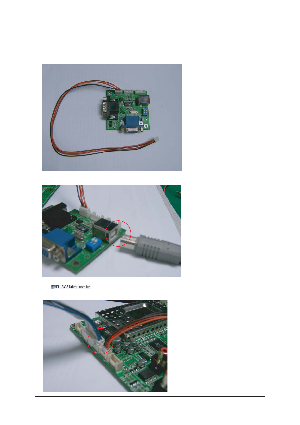
3-5-2 How to Update Flash ROM (with UART JIG)
¡Ø In the usual cases, Update S/W by using RS-232C Cable.
If some problems occur under this condition, update S/W by using UART JIG.
You can use UART JIG with USB Connection.
Install in your PC before using the JIG
Connect 4P Lead connector to Main Board(CN501)
3 Alignments and Adjustments
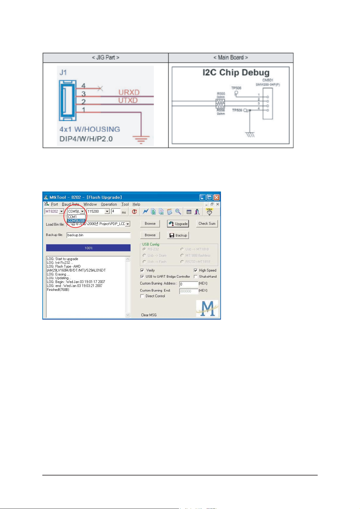
3-17
* Pin Assignment
Turn on the Set (or on Stand by mode)
- Run "MTKtool"
When you run "MTKtool", this Program can detect USB port automatically
Choose USB interface and Update S/W as RS-232C case.

3 Alignments and Adjustments
3-18
Memo
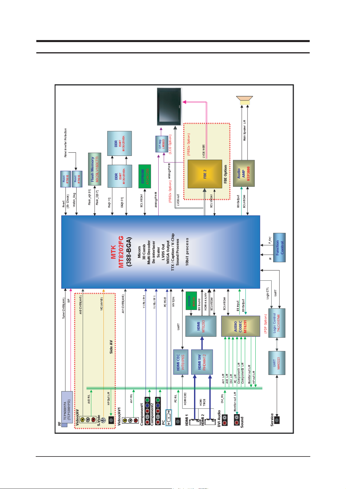
7 Block Diagrams
7-1
7 Block Diagram
- This Document can not be used without Samsung’s authorization

7 Block Diagrams
7-2
Memo

13 Circuit Descriptions
13-1
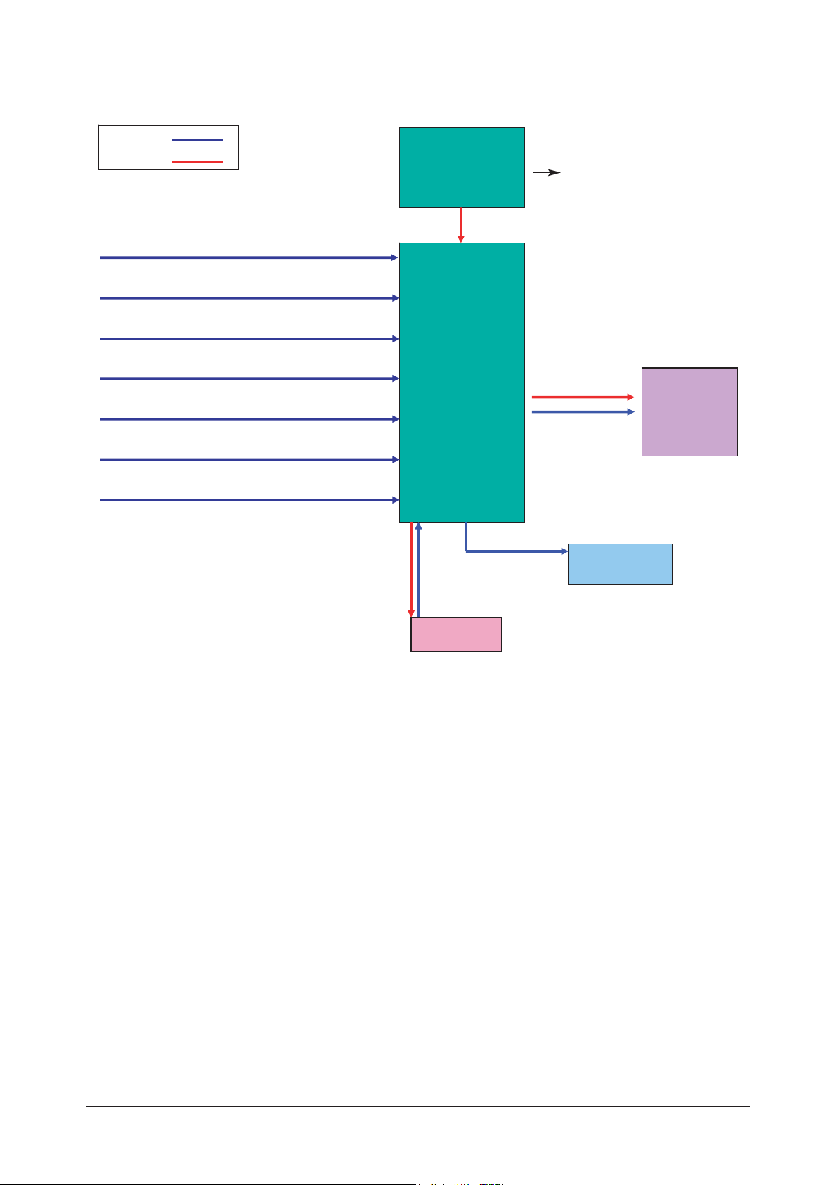
13 Circuit Descriptions
13-1 Block description
RF IN
Scart 1,2
A/V
S-Video
Component
HDMI 1, 2
PC
Main
Board
Panel
T-con
Board
Speaker
IR/LED
Signal
Power
Bordeaux consists of three main blocks
1. Main board : Video signal processing
2. IP board : Power supply & Inverter
3. T-con board : LCD Panel control
IP Board
13 Circuit Descriptions
13-2
Bordeaux consists of three main blocks
1. Main board : Video signal processing
2. SMPS : Power supply
3. T-con board : LCD Panel control
SMPS
INVERTER
RF IN
Scart 1,2
A/V
S-Video
Component
HDMI 1, 2
Main
Board
Panel
T-con
Board
Speaker
IR/LED
Signal
Power
PC
13 Circuit Descriptions
13-3
13-2 Main Block
13 Circuit Descriptions
13-4
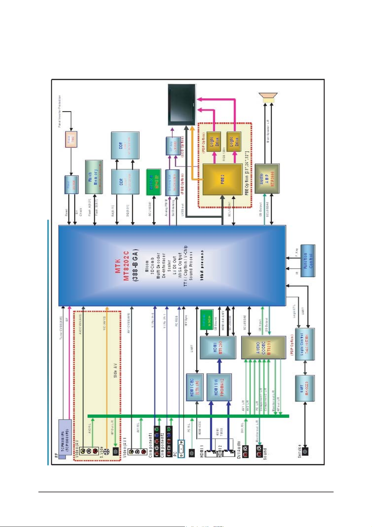
13-3 SMPS Board
13-3-1 26", 32" Power Block
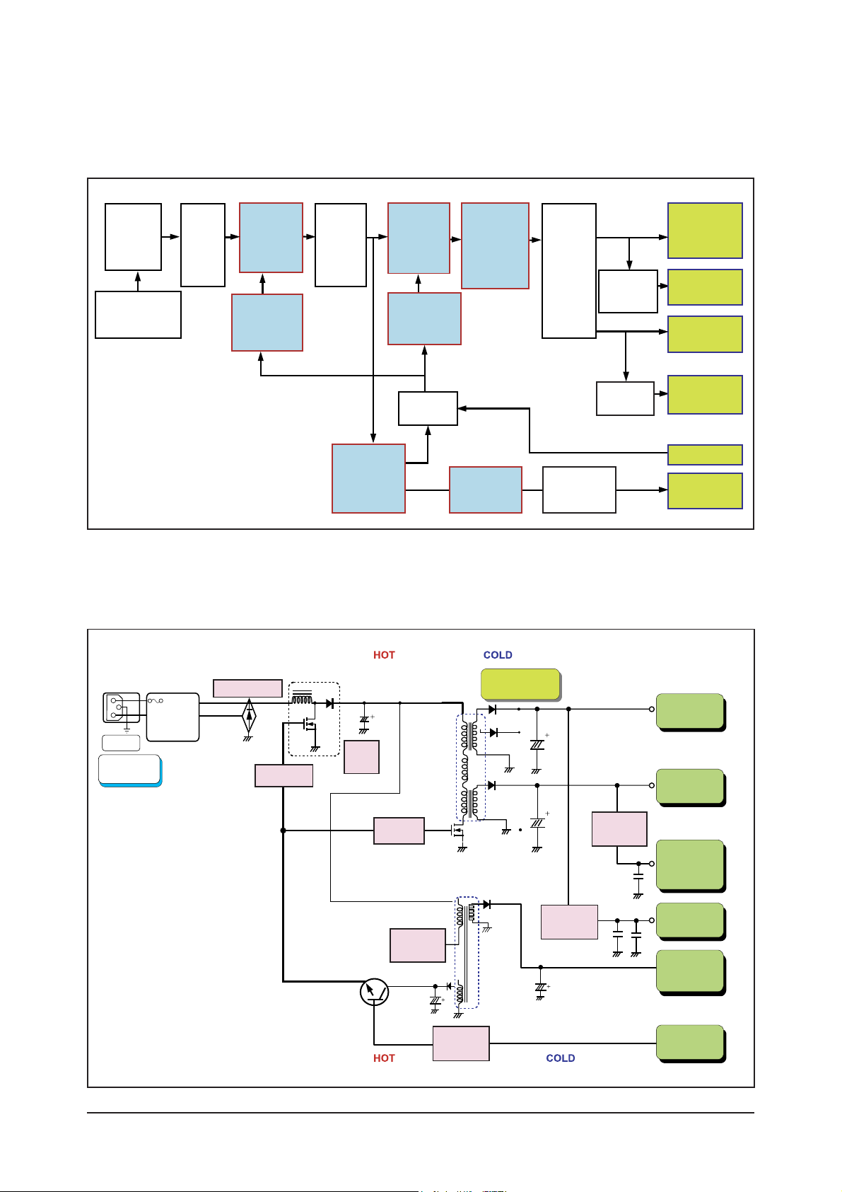
13-3-2 26", 32" SMPS Diagram
Line
Filter
Part
PFC
Switching
Part
Resonance
Switching
Part
Resonance
Transformer
Output
Rectifier
Part
DC/DC
SI-8008HFE
or AP1501A
Inverter
SMPS
24V
Signal
5.3V
Signal
13V
Sound
12V
Stand-By
5.2V
Regulator
KA278R12
Resonance
Controller
MC33067
PFC
Controler
TDA4863
Stand-By
Controller
STR-A6159
AC Input
(90Vac~264Vac)
AC
Rectifier
PFC
Rectifier
On/Off
Control
On/Off
EMI
FILTER
AC Input
90V~264V
INPUT
Rectifier
MC33067
STR-A6159
Current
Resonant Type
450V
150uF
TDA4863
PFC DC
Output
Trans EER4445
Trans EE2020
PFC
Regulator
Sound
+12V
V5D
+5.3V
Stand-By
5.2V
INVERTER
24V
Main
+13V
DC/DC
Converter
On/Off
Control
Power On/Off
Signal
ST-BY
Transformer
Output
Rectifier
Part

13 Circuit Descriptions
13-5
Output
Name
Output Voltage Output Current
Load Characteristics PCB Loc.
Usage Remark
Normal
24.5V
5.3V
12.7V
9.2V
8.0V
0.1V
0.1V
0.01V
0.01V
0.1V
4.0V
5.0V
0.5V
1.1V
0.6V
Pulsating Main B'D Drive -
-
-
-
-
Sound
Stand-by
Drive, Logic,
Buffer,
Image Digital
Image Analog
Main B'D
Main B'D
Main B'D
Main B'D
Constant
Constant
Constant
Constant
3.0V
3.0V
0.3V
0.3V
0.3V
23.52V
~25.48V
5.13V
~5.67V
11.9V
~13.7V
8.83V
~9.57V
5.58V
~8.5V
±
4
±
5
±
7
±
4
±
5
Min Typical PeakRegulation(%) Variable Range
24V
13V
Vamp
ST-BY
5.3V
 Loading...