

Samsung LA26R71B Schematic
TFT-LCD TV
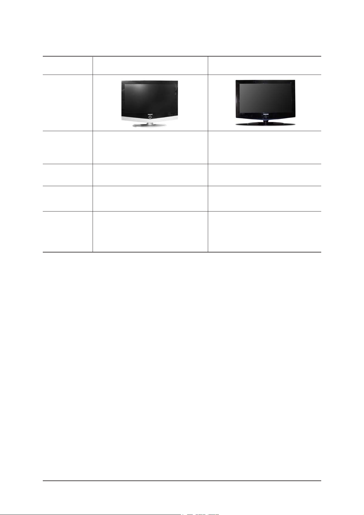
Chassis Model
GBD26KS LA26R71B
GBD32KS LA32R71B
GBD40KS LA40R71B
GBD32KS LA32R71W
Manual
SERVICE
TFT-LCD TV Feature
- Luxurious Slim Design
- Supreme Picture Quality
- Supreme Sound Quality
- Supreme Convenience Quality
- Convenience for Users

ii
Copyright
ⓒ 2006 by Samsung Electronics Co., Ltd.
All rights reserved.
This manual may not, in whole or in part, be copied,
photocopied, reproduced, translated, or converted to any
electronic or machine readable form without prior
written permission of Samsung Electronics Co., Ltd.
LA26R71B / LA32R71B / LA40R71B / LA32R71W
Service Manual
First edition March 2006.
Printed in Korea.
Trademarks
Samsung is the registered trademark of Samsung
Electronics Co., Ltd.
LA26R71B / LA32R71B / LA40R71B / LA32R71W
and Macmaster Cable Adapter are trademarks of
Samsung Electronics Co., Ltd.
Macintosh and Power Macintosh are trademarks of
Apple Computer, Inc.
All other trademarks are the property of their respective
owners.

Contents
11. Precautions
………………………………………………………………………………………………………………………………………
11-1
1-1 Safety Precautions ……………………………………………………………………………………………………………………… 1-1
1-2 Servicing Precautions …………………………………………………………………………………………………………………… 1-2
1-3 Static Electricity Precautions …………………………………………………………………………………………………………… 1-2
1-4 Installation Precautions…………………………………………………………………………………………………………………… 1-3
2
2. Product specifications
…………………………………………………………………………………………………………………………
22-1
2-1 Fashion Feature…………………………………………………………………………………………………………………………… 2-1
2-2 LA26R71B Specifications………………………………………………………………………………………………………………… 2-2
2-3 LA32R71B / LA32R71W Specifications ………………………………………………………………………………………………… 2-3
2-4 LA40R71B Specifications………………………………………………………………………………………………………………… 2-4
2-5 Spec Comparison ………………………………………………………………………………………………………………………… 2-5
2-6 Option Specification ……………………………………………………………………………………………………………………… 2-6
3
3. Alignments and Adjustments
…………………………………………………………………………………………………………………
33-1
3-1 Service Instruction ……………………………………………………………………………………………………………………… 3-1
3-2 How to Access Service Mode …………………………………………………………………………………………………………… 3-2
3-3 Factory Data ……………………………………………………………………………………………………………………………… 3-3
3-4 Service Adjustment ……………………………………………………………………………………………………………………… 3-9
3-5 Software Upgrade ……………………………………………………………………………………………………………………… 3-12
4
4. Troubleshooting
………………………………………………………………………………………………………………………………
44-1
4-1 First Checklist for Troubleshooting ………………………………………………………………………………………………………4-1
4-2 Checkpoints by Error Mode ……………………………………………………………………………………………………………… 4-2
5
5. Exploded View and Parts List
…………………………………………………………………………………………………………………
55-1
5-1 LA26R71B Exploded View ……………………………………………………………………………………………………………… 5-1
5-2 LA26R71B Parts list ……………………………………………………………………………………………………………………… 5-2
5-3 LA32R71B Exploded View ……………………………………………………………………………………………………………… 5-3
5-4 LA32R71B Parts list ……………………………………………………………………………………………………………………… 5-4
5-5 LA32R71W Parts list ……………………………………………………………………………………………………………………… 5-4
5-6 LA40R71B Exploded View ……………………………………………………………………………………………………………… 5-5
5-7 LA40R71B Parts list ……………………………………………………………………………………………………………………… 5-6
6
6.
Electrical Parts List
……………………………………………………………………………………………………………………………
6
6-1
6-1 LA26R71B Parts List……………………………………………………………………………………………………………………… 6-1
6-2 LA32R71B Parts List …………………………………………………………………………………………………………………… 6-19
6-3 LA40R71B Parts List …………………………………………………………………………………………………………………… 6-35
6-4 LA32R71W Parts List …………………………………………………………………………………………………………………… 6-52
7
7. Block Diagram
…………………………………………………………………………………………………………………………………
77-1

Contents
88. Wiring Diagram
…………………………………………………………………………………………………………………………………
88-1
8-1 LA26R71B / LA32R71B / LA40R71B / LA32R71W Wiring Diagram………………………………………………………………… 8-1
8-2 Main Board Layout ……………………………………………………………………………………………………………………… 8-2
8-3 PIN characteristic ………………………………………………………………………………………………………………………… 8-3
8-4 Power Board Layout ……………………………………………………………………………………………………………………… 8-6
9
9. Schematic Diagrams
……………………………………………………………………………………………………………………………
99-1
9-1 Power_Sound Schematic Diagram ……………………………………………………………………………………………………… 9-1
9-2 Jack Schematic Diagram ………………………………………………………………………………………………………………… 9-2
9-3 Micom Schematic Diagram ……………………………………………………………………………………………………………… 9-3
9-4 SVP-PX/PX-Power/LBE-Option Schematic Diagram ………………………………………………………………………………… 9-4
9-5 Application Schematic Diagram ………………………………………………………………………………………………………… 9-5
1
10. Operating Instructions and Installation
………………………………………………………………………………………………………
110-1
10-1 Front …………………………………………………………………………………………………………………………………… 10-1
10-2 Connection Panel ……………………………………………………………………………………………………………………… 10-2
10-3 Remote control ………………………………………………………………………………………………………………………… 10-5
10-4 Installing the Stand …………………………………………………………………………………………………………………… 10-6
10-5 Installing the Wall Mount Kit ………………………………………………………………………………………………………… 10-6
1
11. Disassembly and Reassembly
………………………………………………………………………………………………………………
111-1
11-1 Disassembly …………………………………………………………………………………………………………………………… 11-1
11-2 Reassembly …………………………………………………………………………………………………………………………… 11-5
1
12. PCB Diagram
…………………………………………………………………………………………………………………………………
112-1
12-1 26" Main PCB Diagram ……………………………………………………………………………………………………………… 12-1
12-2 32", 40" Main PCB Diagram ……………………………………………………………………………………………………………12-2
12-3 26" SMPS board ……………………………………………………………………………………………………………………… 12-3
12-4 32" SMPS board ……………………………………………………………………………………………………………………… 12-4
12-5 40" IP Board …………………………………………………………………………………………………………………………… 12-5
1
13. Circuit Descriptions
……………………………………………………………………………………………………………………………
113-1
13-1 Block description ……………………………………………………………………………………………………………………… 13-1
13-2 Main Block ……………………………………………………………………………………………………………………………… 13-3
13-3 SMPS Board …………………………………………………………………………………………………………………………… 13-4
1
14. Reference Infomation
………………………………………………………………………………………………………………………
114-1
14-1 Technical Terms ……………………………………………………………………………………………………………………… 14-1
14-2 Pin Assignments ……………………………………………………………………………………………………………………… 14-4
14-3 Timing Chart …………………………………………………………………………………………………………………………… 14-6
14-4 Panel Description …………………………………………………………………………………………………………………… 14-10

Samsung Electronics Co.,Ltd.
416, Maetan-3Dong, Yeongtong-Gu, Suwon City,
Gyeonggi-Do, Korea, 443-742
Printed in Korea
P/N : BN82-00139H-01
URL : http://itself.sec.samsung.co.kr/
- This Service Manual is a property of
Samsung Electronics Co., Ltd.
Any unauthorized use of Manual can be
punished under applicable International
and/or domestic law.

2 Product Specifications
2-1
2 Product specifications
2-1 Fashion Feature
Supreme Digital Interface & Networking
-With a built-in HD digital tuner, it supports HD broadcasting with no particular set-top box and provides
simple access with a single remote control.
Excellent Picture Quality
-DNIe technology provides life-like clear images.
Dynamic Contrast
-Automatically detects the input visual signal and adjusts to create optimum contrast.
Energy saving
-Adjusts the brightness of TV so as to reduce the power consumption.
SRS TruSurround XT
-SRS TruSurround XT provides a virtual Dolby surround system.
Convenience
-The TV utilizes the HDMI system to implement perfect digital sound and picture quality.
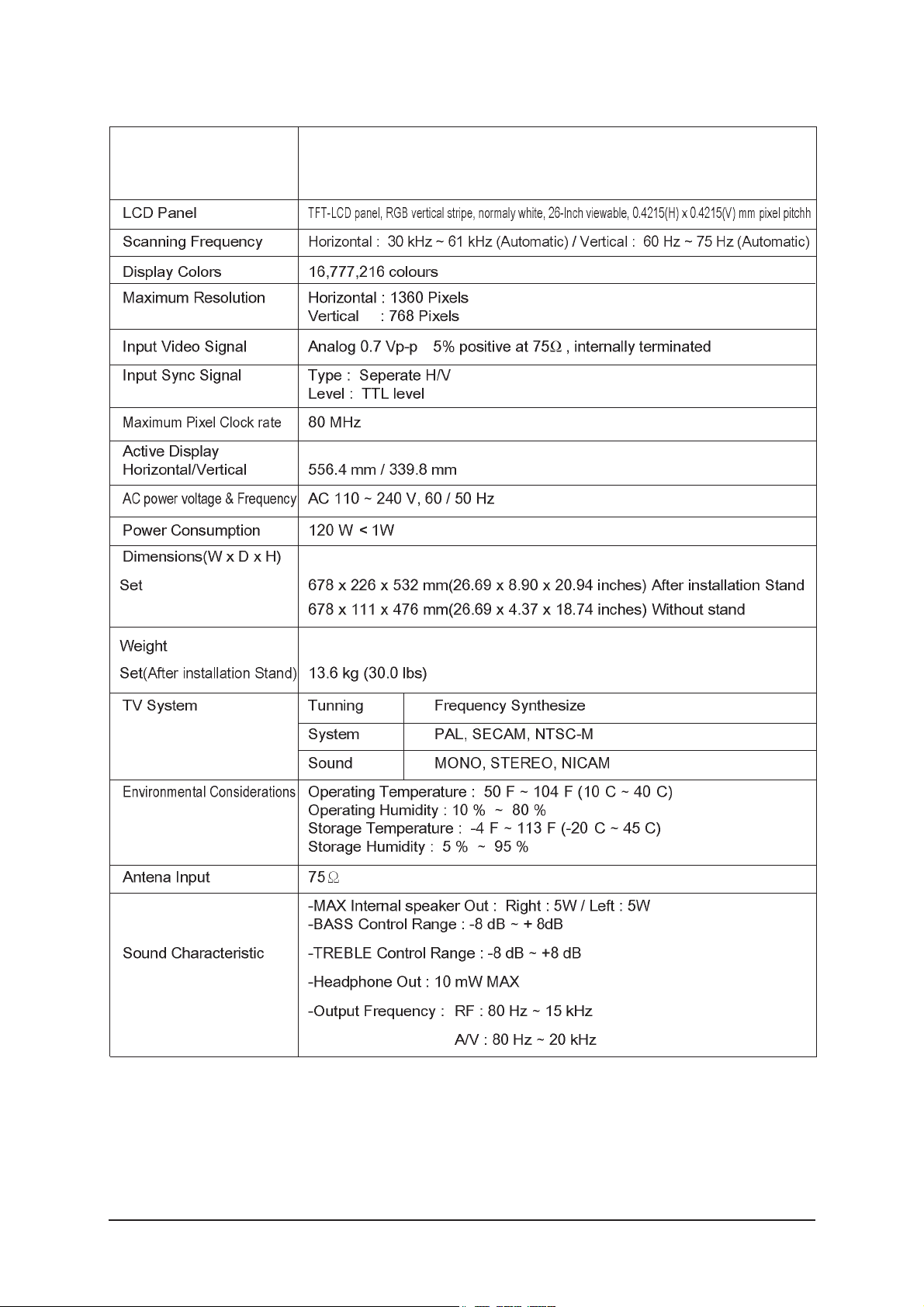
2-2 LA26R71B / LA26R71W Specifications
±
° ° ° °
° ° ° °
2 Product Specifications
2-2
Item
Description
2 Product Specifications
2-3
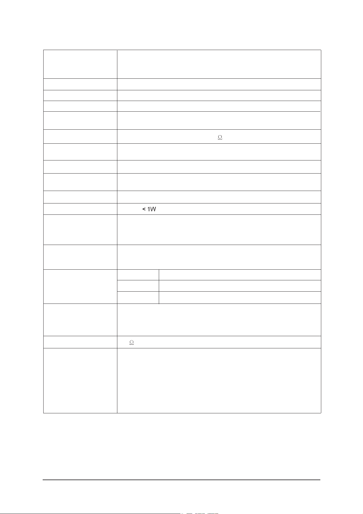
2-3 LA32R71B / LA32R71W Specifications
LCD Panel
TFT-LCD panel, RGB vertical stripe, normaly white, 32-Inch viewable, 0.511 (H) x 0.511 (V) mm pixel pitchh
Scanning Frequency Horizontal : 30 kHz ~ 61 kHz (Automatic) / Vertical : 60 Hz ~ 75 Hz (Automatic)
Display Colors 16,777,216 colours
Maximum Resolution Horizontal : 1360 Pixels
Vertical : 768 Pixels
Input Video Signal Analog 0.7 Vp-p ± 5% positive at 75
, internally terminated
Input Sync Signal Type : Seperate H/V
Level : TTL level
Maximum Pixel Clock rate
80 MHz
Active Display
Horizontal/Vertical 556.4 mm / 339.8 mm
AC power voltage & Frequency AC 110 ~ 240V, 60 / 50 Hz
Power Consumption 152 W
Dimensions(W x D x H)
Set 800 x 252 x 602.5 mm(31.5 x 9.92 x 23.72 inches)After installation Stand
800 x 79.6 x 564 mm(31.5 x 3.13 x 22.20 inches) Without stand
Weight
Set
(After installation Stand) 14.8 kg (32.62 lbs)
TV System Tunning Frequency Synthesize
System PAL, SECAM, NTSC-M
Sound MONO, STEREO, NICAM
Environmental Operating Temperature : 50°F ~ 104°F (10°C ~ 40°C)
Considerations Operating Humidity : 10 % ~ 80 %
Storage Temperature : -4°F ~ 113°F (-20°C ~ 45°C)
Storage Humidity : 5 % ~ 95 %
Antena Input 75
-MAX Internal speaker Out : Right : 10W / Left : 10W
-BASS Control Range : -8 dB ~ + 8dB
Sound Characteristic -TREBLE Control Range : -8 dB ~ +8 dB
-Headphone Out : 10 mW MAX
-Output Frequency : RF : 80 Hz ~ 15 kHz
A/V : 80 Hz ~ 20 kHz
Item
Description
2 Product Specifications
2-4
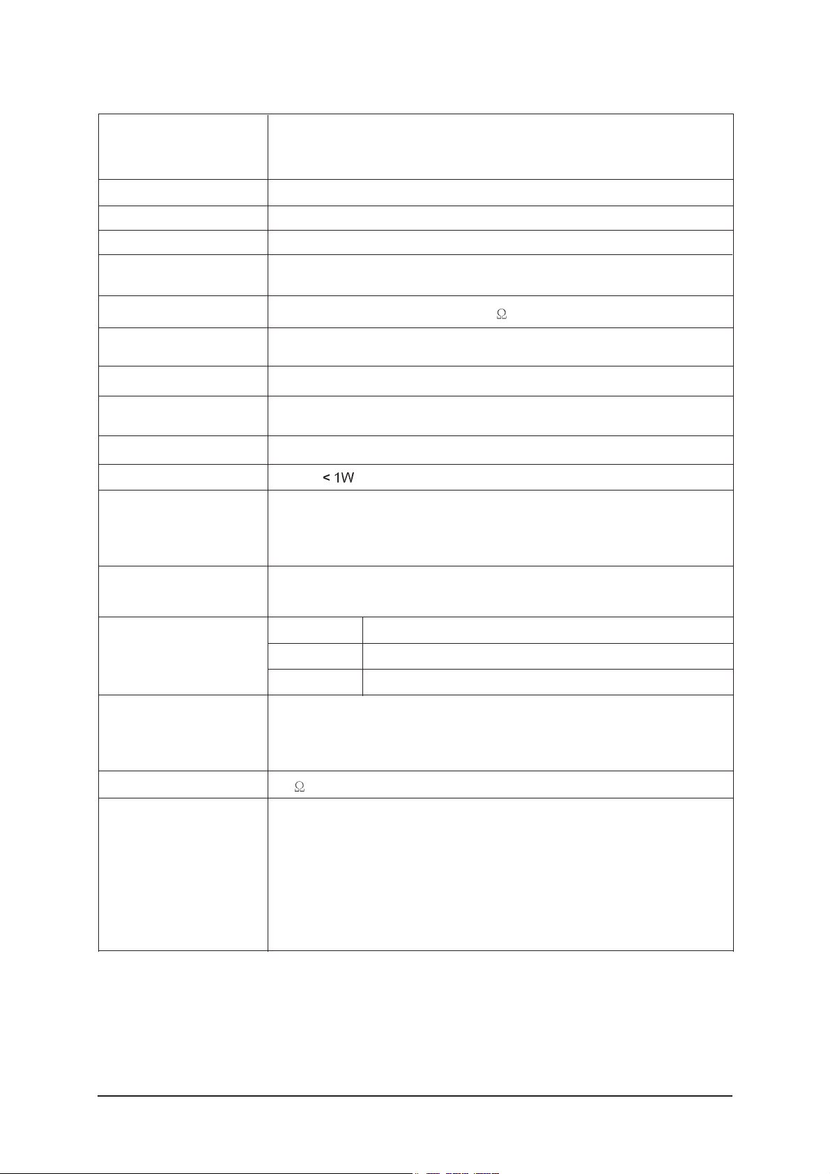
2-4 LA40R71B Specifications
LCD Panel
TFT-LCD panel, RGB vertical stripe, normaly white, 40-Inch viewable, 0.648(H) x 0.216(V) mm pixel pitch
Scanning Frequency Horizontal : 30 kHz ~ 61 kHz (Automatic) / Vertical : 60 Hz ~ 75 Hz (Automatic)
Display Colors 16,777,216 colours
Maximum Resolution Horizontal : 1360 Pixels
Vertical : 768 Pixels
Input Video Signal Analog 0.7 Vp-p ± 5% positive at 75
, internally terminated
Input Sync Signal Type : Seperate H/V
Level : TTL level
Maximum Pixel Clock rate
80 MHz
Active Display
Horizontal/Vertical 556.4 mm / 339.8 mm
AC power voltage & Frequency AC 110 ~ 240V, 60 / 50 Hz
Power Consumption 205 W
Dimensions(W x D x H)
Set
1004 x 330 x 749 mm(39.52 x 12.99 x 29.49 inches) After installation Stand
31004 x 115 x 680 mm(39.52 x 4.52 x 26.77 inches) Without stand
Weight
Set
(After installation Stand) 30.2 kg (66.58 lbs)
TV System Tunning Frequency Synthesize
System PAL, SECAM, NTSC-M
Sound MONO, STEREO, NICAM
Environmental Considerations Operating Temperature : 50°F ~ 104°F (10°C ~ 40°C)
Operating Humidity : 10 % ~ 80 %
Storage Temperature : -4°F ~ 113°F (-20°C ~ 45°C)
Storage Humidity : 5 % ~ 95 %
Antena Input 75
-MAX Internal speaker Out : Right : 10W / Left : 10W
-BASS Control Range : -8 dB ~ + 8dB
Sound Characteristic -TREBLE Control Range : -8 dB ~ +8 dB
-Headphone Out : 10 mW MAX
-Output Frequency : RF : 80 Hz ~ 15 kHz
A/V : 80 Hz ~ 20 kHz
Item
Description
2-5 Spec Comparison
2 Product Specifications
2-5
LA26R51B / LA32R51B / LA40R51B
Model
Design
Frequency
Horizontal
Vertical
Display Color
30 ~ 61 kHz
60 ~ 75 Hz
16,777,216 colors
30 ~ 61 kHz
60 ~ 75 Hz
16,777,216 colors
PC Resolution
Maximum mode
Input Signal
Sync Signal
Video Signal
Power
Consumption
Normal
Power Saving
140W / 184W / 285W
< 1W
100W / 152W / 205W
< 1W
H/V Separate, TTL, P. or N.
0.7 Vp-p @ 75ohm
H/V Separate, TTL, P. or N.
0.7 Vp-p @ 75ohm
WXGA, 1360 x 768 @ 60 Hz WXGA, 1360 x 768 @ 60 Hz
LA26R71B / LA26R71W / LA32R71B /
LA40R71B / LA32R71W
2 Product Specifications
2-6
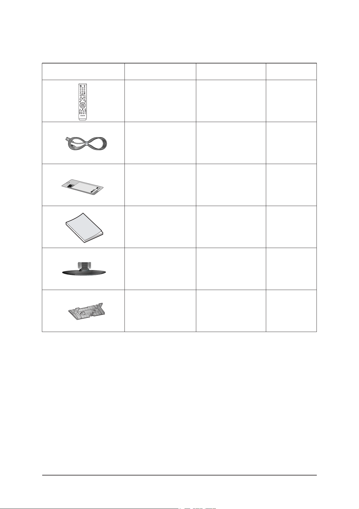
2-6 Option Specification
Item Item Name
Remote Control
&
Batteries (AAA x 2)
Power Cord
Cleaning Cloth
Owner's
Instructions
Stand
Cover-Bottom
BN59-00507A
3903-000067
BN63-001798A
BN68-01010A
26" : BN90-00848A
32" : BN90-00842A
40" : BN90-00847A
26" : BN63-02323A
32" : BN63-02323A
40" : BN63-02366A
Code.No Remark

5 Exploded View & Parts List
5-1
5 Exploded View and Parts List
- You can search for updated part codes through ITSELF web site.
URL : http://itself.sec.samsung.co.kr/
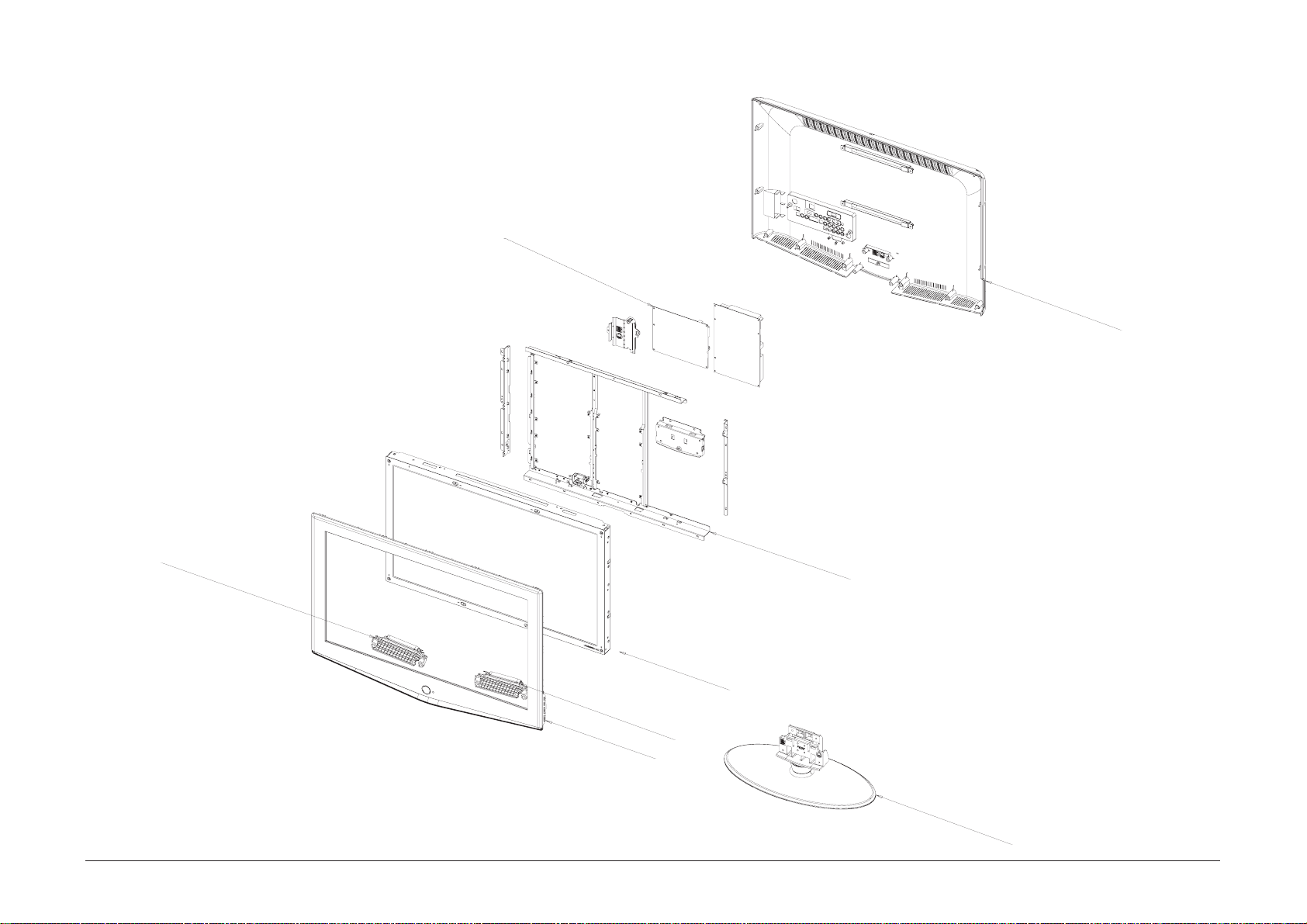
5-1 LA26R71B Exploded View
M0014
M0013
T0175
T0159
T0447
M0215
T0175
M0013
T0003

5 Exploded View & Parts List
5-2
Location Code.No Item & Specification Q'ty SA/SNA Remark
T0003 BN96-03012F ASSY COVER P-FRONT;26R71,SO,ABS+PMMA,HB, 1 SA
T0175 BN96-03053A ASSY SPEAKER P;16ohm,Bordeuax 26,Left,5W 1 SA
T0175 BN96-03054A ASSY SPEAKER P;16ohm,Bordeuax 26,Right,5 1 SA
M0215 BN07-00254A LCD-PANEL;T260XW02,8bit,626.0*373.0*50.0 1 SA
T0447 BN96-03008C ASSY BRACKET P-PANEL;BORDEAUX,26,AUO,SMP 1 SNA
M0014 BN94-00879A ASSY PCB MAIN;LA26R71B,BORDEAUX,ASIA 1 SA
T0159 BN96-03058A ASSY PCB P-SMPS;Bordeaux 26 PFC,LE26R71B 1 SA
M0013 BN96-03014E ASSY COVER P-REAR;26R71,SO,ABS+PMMA,BK23 1 SA
M0013 BN96-03017A ASSY STAND P-BASE;26R71,ABS+PMMA,HB,BK23 1 SA
5-2 LA26R71B Parts list

5 Exploded View & Parts List
5-3
5-3 LA26R71W Exploded View
M0014
M0013
T0175
T0159
T0447
M0215
T0175
M0013
T0003
5 Exploded View & Parts List
5-4
Location Code.No Item & Specification Q'ty SA/SNA Remark
T0003 BN96-03012P ASSY COVER P-FRONT;26R71,SO,(WHITE),ABS+ 1 S.A
T0175 BN96-03053A ASSY SPEAKER P;16ohm,Bordeuax 26,Left,5W 1 S.A
T0175 BN96-03054A ASSY SPEAKER P;16ohm,Bordeuax 26,Right,5 1 S.A
M0215 BN07-00254A LCD-PANEL;T260XW02,8bit,626.0*373.0*50.0 1 S.A
T0447 BN96-03008C ASSY BRACKET P-PANEL;BORDEAUX,26,AUO,SMP 1 S.N.A
M0014 BN94-00879B ASSY PCB MAIN;LA26R71BX/* 1 S.N.A
T0159 BN96-03058A ASSY PCB P-SMPS;Bordeaux 26 PFC,LE26R71B 1 S.A
M0013 BN96-03014L ASSY COVER P-REAR;26R71,SO(WHITE),ABS+PM 1 S.A
M0013 BN96-03017B ASSY STAND P-BASE;26R71,ABS+PMMA,HB,WH12 1 S.A
5-4 LA26R71W Parts list
5 Exploded View & Parts List
5-5
5-5 LA32R71B / LA32R71W Exploded View
M0014
M0013
T0175
T0447
M0215
T0175
T0003
M0013
5 Exploded View & Parts List
5-6
5-6 LA32R71B Parts list
Location Code.No Item & Specification Q'ty SA/SNA Remark
T0003 BN96-02996D ASSY COVER P-FRONT;32R71,SO,ABS+PMMA,HB, 1 SA
T0175 BN96-03002A ASSY SPEAKER P;8ohm,Bordeuax 32"/37"/40" 1 SA
T0175 BN96-03003A ASSY SPEAKER P;8ohm,Bordeuax 32"/37"/40" 1 SA
M0215 BN07-00247A LCD-PANEL;LTA320WT-L14,8BIT,760*450*50.0 1 SA
T0447 BN96-02999A ASSY BRACKET P-PANEL;BORDEAUX,32,AMLCD,S 1 SNA
M0014 BN94-00876A ASSY PCB MAIN;LA32R71B,BORDEAUX,ASIA 1 SA
M0013 BN96-02997D ASSY COVER P-REAR;32R71,SO,ABS+PMMA,HB,B 1 SA
M0013 BN96-02998A ASSY STAND P-BASE;32R71,ABS+PMMA,HB,BK23 1 SA
5-7 LA32R71W Parts list
Location Code.No Item & Specification Q'ty SA/SNA Remark
T0003 BN96-03677E ASSY COVER P-FRONT;32R71,SO(WHITE,AM),AB 1 S.A
T0175 BN96-04207A ASSY SPEAKER P;8ohm,VE Type,Left,10W,Hor 1 S.N.A
T0175 BN96-04208A ASSY SPEAKER P;8ohm,VE Type,Right,10W,Ho 1 S.A
M0215 BN07-00247A LCD-PANEL;LTA320WT-L14,-,8BIT,760*450*50 1 S.A
T0447 BN96-02999A ASSY BRACKET P-PANEL;BORDEAUX,32,AMLCD,S 1 S.N.A
M0014 BN94-00876B ASSY PCB MAIN;LA32R71BX/* 1 S.A
M0013 BN96-02998B ASSY STAND P-BASE;32R71,-,ABS+PMMA,HB,WH 1 S.A
M0013 BN96-02997M ASSY COVER P-REAR;32R71,SO(WHITE),ABS+PM 1 S.A

5 Exploded View & Parts List
5-7
5-8 LA40R71B Exploded View
M0014
M0013
T0101
T0175
T0447
M0215
T0175
T0003
M0013

5 Exploded View & Parts List
5-8
5-9 LA40R71B Parts list
Location Code.No Item & Specification Q'ty SA/SNA Remark
T0003 BN96-03011D ASSY COVER P-FRONT;40R71,SO,ABS+PMMA,HB, 1 SA
T0175 BN96-03002A ASSY SPEAKER P;8ohm,Bordeuax 32"/37"/40" 1 SA
T0175 BN96-03003A ASSY SPEAKER P;8ohm,Bordeuax 32"/37"/40" 1 SA
M0215 BN07-00264A LCD-PANEL;LTA400WT-L01,8bit,952*551*51.0 1 SA
T0447 BN96-03009C ASSY BRACKET P-PANEL;BORDEAUX,40,AMLCD,I 1 SNA
M0014 BN94-00880A ASSY PCB MAIN;LA40R71BX,BORDEAUX,ASIA 1 SA
T0101 BN61-02427A BRACKET-WALL;BORDEAUX 40,SECC,T1.2 1 SNA
M0013 BN96-03013D ASSY COVER P-REAR;40R71,SO,ABS+PMMA,HB,B 1 SA
M0013 BN96-03016A ASSY STAND P-BASE;40R71,ABS+PMMA,HB,BK23 1 SA
11 Disassembly and Reassembly
11-1
11 Disassembly and Reassembly
This section of the service manual describes the disassembly and reassembly procedures for the TFT-LCD
TV.
WARNING : This monitor contains electrostatically sensitive devices. Use caution when
handling these components.
11-1 Disassembly
Cautions : 1. Disconnect the monitor from the power source before disassembly.
2. Follow these directions carefully; never use metal instruments to pry apart the
cabinet.
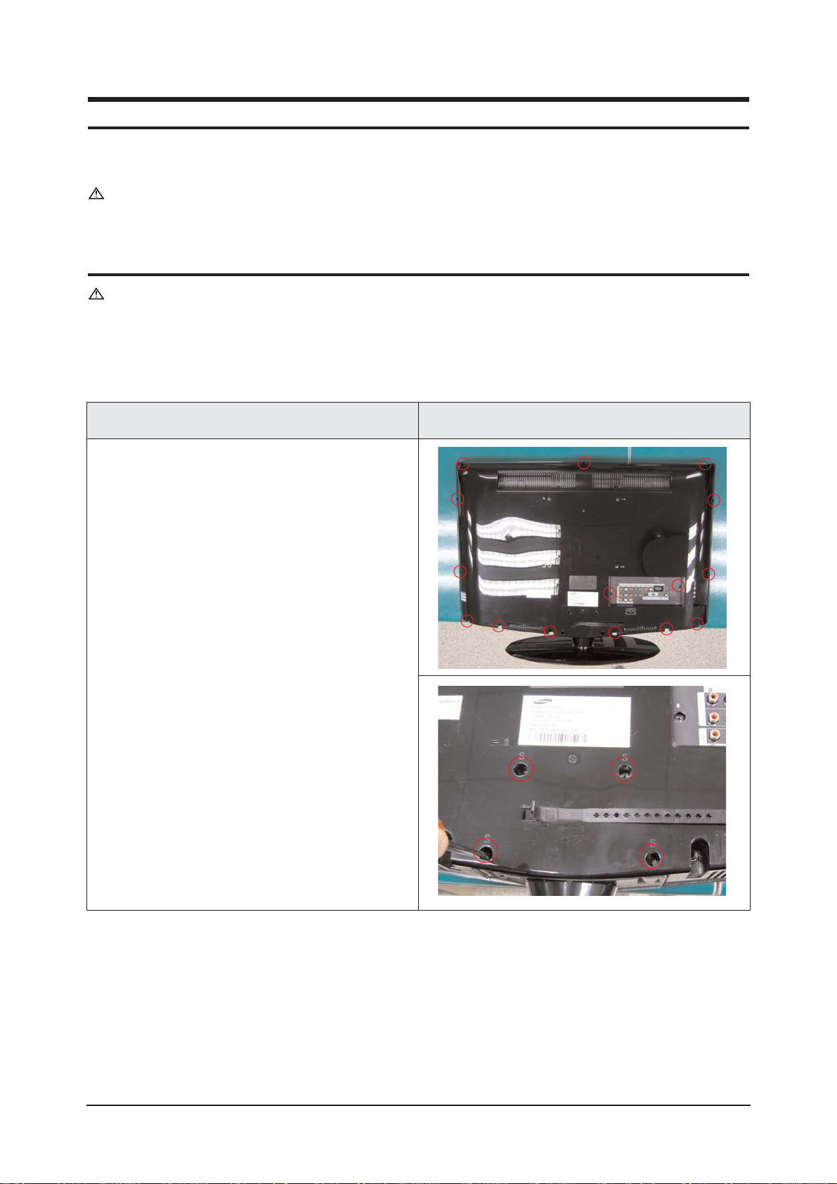
1. Place monitor face down on cushioned table.
Remove 15 screws from the rear cover.
Remove 4 screws from the stand.
Description Picture Description

11 Disassembly and Reassembly
11-2
3. Remove screws from the stand BRKT and lift
up the stand BRKT.
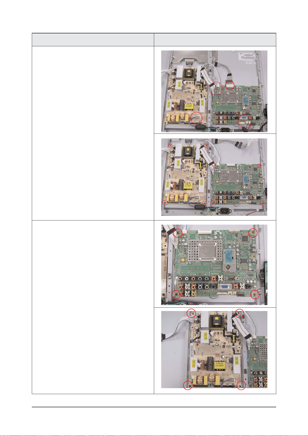
Description Picture Description
2. Lift up the rear cover and remove the stand.
11 Disassembly and Reassembly
11-3
5. Remove screws from the boards and lift up the
boards.
Description Picture Description
4. Disonnect cables from the boards.

11 Disassembly and Reassembly
11-4
7. Lift up the panel BRKT.
Description Picture Description
6. Remove screw from the side connector.
Remove screws from the panel BRKT.

11 Disassembly and Reassembly
11-5
Description Picture Description
8. Lift up the LCD panel.
11-2 Reassembly
Reassembly procedures are in the reverse order of disassembly procedures.

11 Disassembly and Reassembly
11-6
Memo

4 Troubleshooting
4-1
4 Troubleshooting
4-1 First Checklist for Troubleshooting
1. Check the various cable connections first.
- Check to see if there is a burnt or damaged cable.
- Check to see if there is a disconnected cable connection or a connection is too loose.
- Check to see if the cables are connected according to the connection diagram.
2. Check the power input to the Main Board.
3. Check the voltage in and out between the SMPS Main Board, between the SMPS
INVERTER Board, and between the Main LVDS Boards.
4 Troubleshooting
4-2
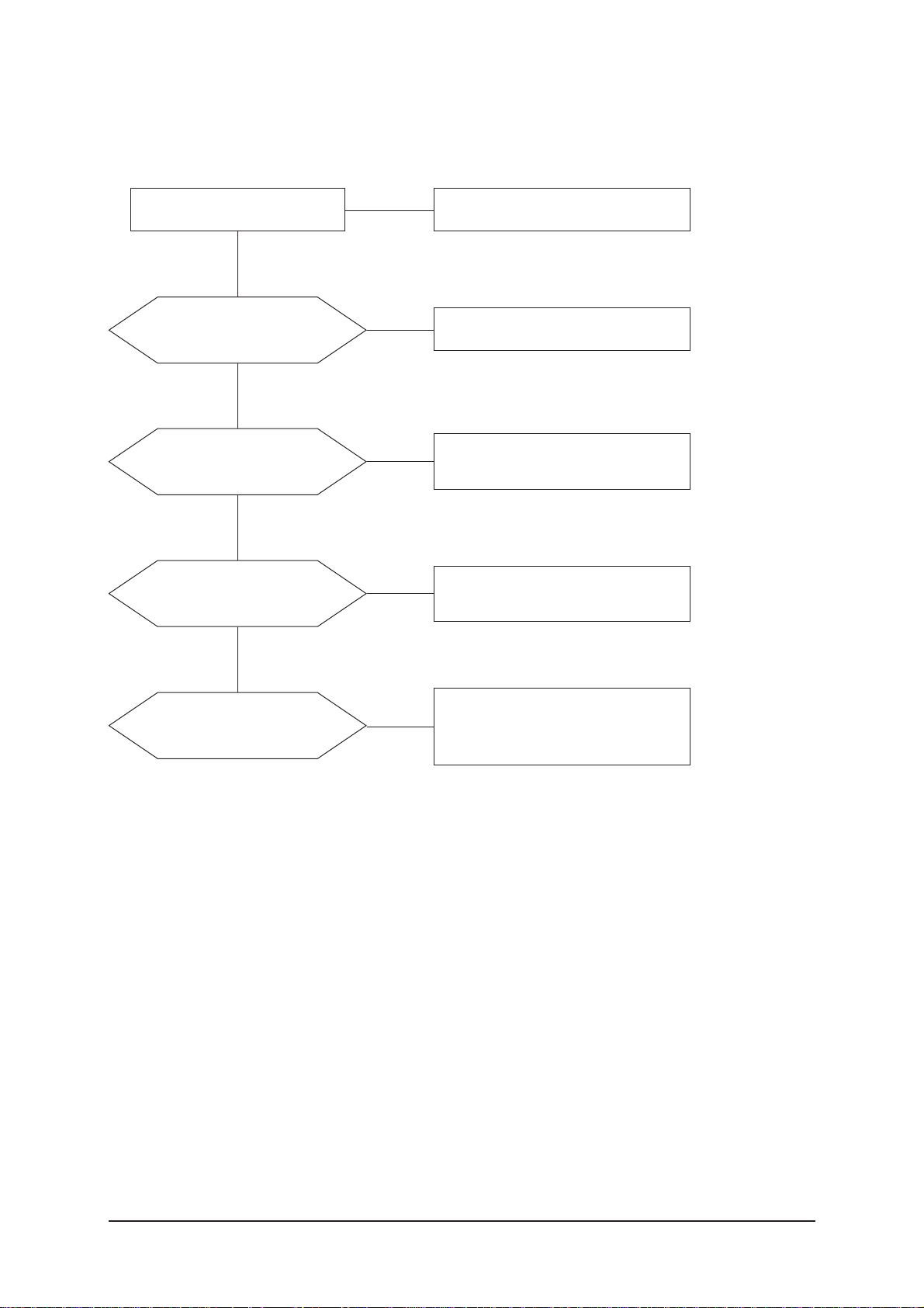
4-2-1 No Power
4-2 Checkpoints by Error Mode
Does proper DC 12V
appear at CN800?
Change a Assy PCB Power.
Yes
Yes
No
Check a connection a power cable.
No
Does proper DC A3.3V,
A5V appear at
C854, C866?
Check a IC809, IC802.
Change a main PCB ass'y.
Yes
No
Does proper DC 5V, 3.3V,
1.8V appear at C811, C853,
C833?
Check a IC803, IC805, IC813, IC307.
Change a main PCB ass'y
Yes
A power is supplied to set?
Check a other function.
(No picture part)
Replace a lcd panel.
No
No
LAMP off, power indicator
LED red color?

4 Troubleshooting
4-3
4-2-2 No Video (Analog PC)
Check a PC source and check
the connection of DSUB cable?
Input a analog PC signal and
connected cable(DPMS).
Yes
Does the signal appear at
#30, 22, 38(R, G, B) of IC500?
PC cable. Change a PC
cable. Change a main PCB ass'y.
Yes
Power Indicator is off.
Lamp on, no video.
No
No
1
Does the digital data appear
at the output of
LVDS (R563_OP~R572_OP)?
Check a IC500
Change a main PCB ass'y.
Yes
Check a LVDS cable?
Replace a lcd panel?
Please, Call to Samsung Co. LTD.
Yes
No
No
4 Troubleshooting
4-4
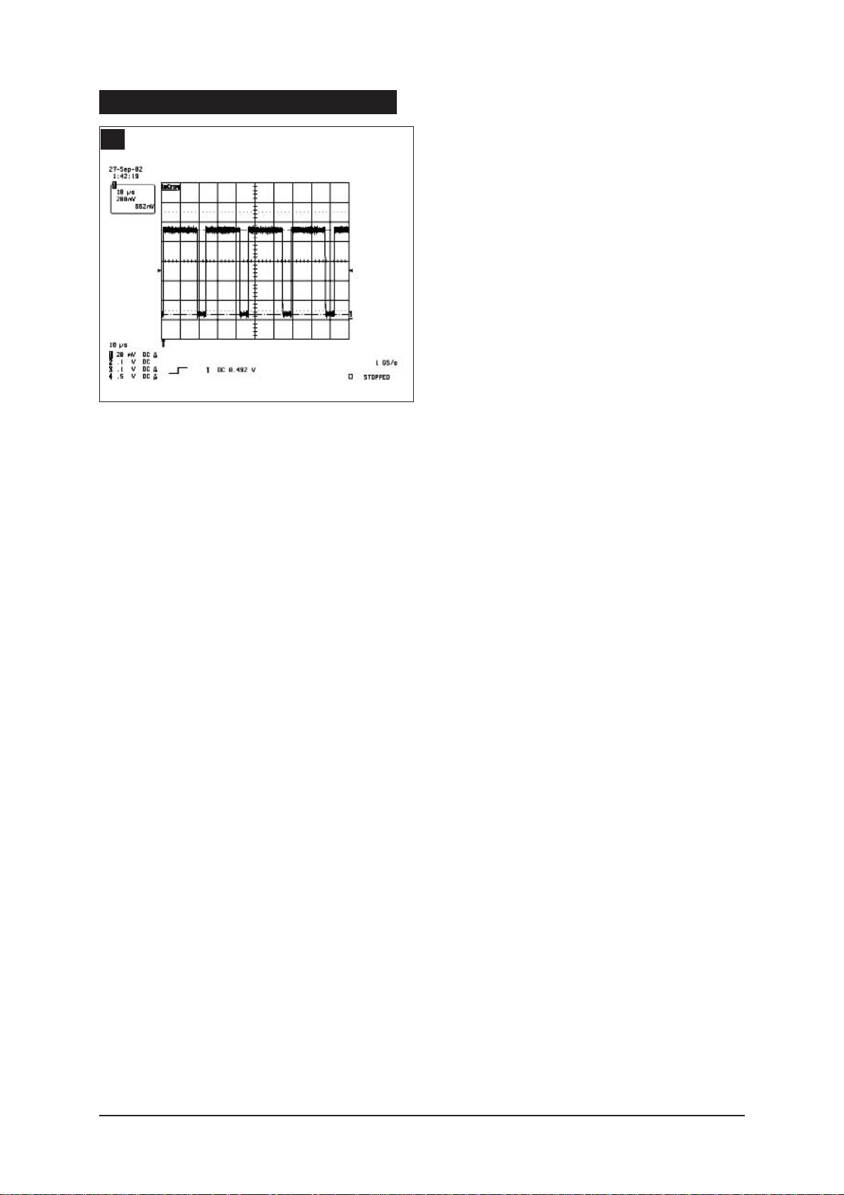
WAVEFORMS
1
R,G,B Output Signal of IC500

4 Troubleshooting
4-5
4-2-3 No Video (Digital-HDMI)
Check the connection
of HDMI cable?
Input a HDMI cable.
Yes
Does the digital data appear at
R503~R510?
Check a a IC 500
Change a main PCB ass'y.
Yes
Does the digital data
appear at output of IC500
LVDS(R563_OP~R572_OP)?
Check a IC500
Change a main PCB ass'y.
Yes
Check a LVDS cable?
Replace lcd panel?
Please, Call to Samsung Co. LTD.
Yes
Power Indicator is off.
Lamp on, no video.
No
No
No
No
3
2
 Loading...