

LCD-TV
SERVICE
Manual
TFT-LCD TV Contents
LA26A450C1/LA26A350C1
/LA32A450C1/LA32A350C1
LA37A450C1/LA37A350C1
Refer to the service manual in the GSPN (see the rear cover) for the more information.
Chassis : GCR26ASA
GCR32CCN
GCR32TSA
GCR37ASA
GCR37CCN
Model : LA26A450C1
LA26A350C1
LA32A450C1
LA32A350C1
LA37A450C1
LA37A350C1
1. Precautions
2. Product specications
3. Disassembly and
Reassembly
4. Troubleshootin
g
5. Exploded View & Part Lis
t
6. Wiring Diagra
m
7. Schematic Diagra
m

Contents
1. Precautions .............................................................................................................. 1-1
1-1. Safety Precautions ......................................................................................................... 1-1
1-2. Servicing Precautions .....................................................................................................1-2
1-3. Electrostatically Sensitive Devices (ESD) Precautions .................................................. 1-2
1-4. Installation Precautions .................................................................................................. 1-3
2. Product specications ............................................................................................ 2-1
2-1. Feature & Specications ................................................................................................. 2-1
2-3. Spec Comparison to the Old Models .............................................................................. 2-6
2-4. Accessories .................................................................................................................... 2-7
3. Disassembly and Reassemble ............................................................................... 3-1
3-1. Disassembly ................................................................................................................... 3-1
4. Troubleshooting ...................................................................................................... 4-1
4-1. Troubleshooting .............................................................................................................. 4-1
4-2. Alignments and Adjustments ........................................................................................ 4-15
4-3. Factory Mode Adjustments ........................................................................................... 4-16
4-4. White Balance - Calibration .......................................................................................... 4-19
4-5. White Ratio (Balance) Adjustment ................................................................................ 4-21
4-6. HOW TO UPGRADE .................................................................................................... 4-22
5. Exploded View & Part List ...................................................................................... 5-1
5-1. LA26A450C1X / LA26A350C1X Exploded View ............................................................ 5-1
5-2. LA32A450C1X / LA32A350C1X Exploded View ............................................................ 5-3
5-3. LA37A450C1X / LA37A350C1X Exploded View ............................................................ 5-5
5-4. LA26A450C1X Parts List ................................................................................................ 5-7
5-5. LA32A450C1X Parts List .............................................................................................. 5-32
5-6. LA37A450C1X Parts List .............................................................................................. 5-57
6. Wiring Diagram ........................................................................................................ 6-1
6-1. Wiring Diagram ............................................................................................................... 6-1
6-2. Wiring Picture ................................................................................................................. 6-4
6-3. Connector Functions ...................................................................................................... 6-5
6-4. Cables ............................................................................................................................ 6-6
GSPN (Global Service Partner Network)
Area Web Site
North America
http://service.samsungportal.com
Latin America
http://latin.samsungportal.com
CIS http://cis.samsungportal.com
Europe http://europe.samsungportal.com
China http://china.samsungportal.com
Asia http://asia.samsungportal.com
Mideast & Africa
http://mea.samsungportal.com
This Service Manual is a property of Samsung Electronics Co.,Ltd.
Any unauthorized use of Manual can be punished under applicable
International and/or domestic law.
© 2008 Samsung Electronics Co.,Ltd.
All rights reserved.
Printed in Korea
P/N: BN82-00339B-00
4-1
4. Troubleshooting
4. Troubleshooting
4-1. Troubleshooting
Check the various cable connections rst.
• Check to see if there is a burnt or damaged cable.
• Check to see if there is a disconnected or loose cable connection.
• Check to see if the cables are connected according to the connection diagram.
Check the power input to the Main Board.
Check internal Pattern FBE3 if there is some picture noise.
FBE3: Factory mode(Info - MENU - MUTE - power on_ -> 4. Advanced menu -> Option block->
FBE->Pattern Select
Press right button of Remocon.
If FBE3 NG,change the main Board
1.
2.
4-2
4. Troubleshooting
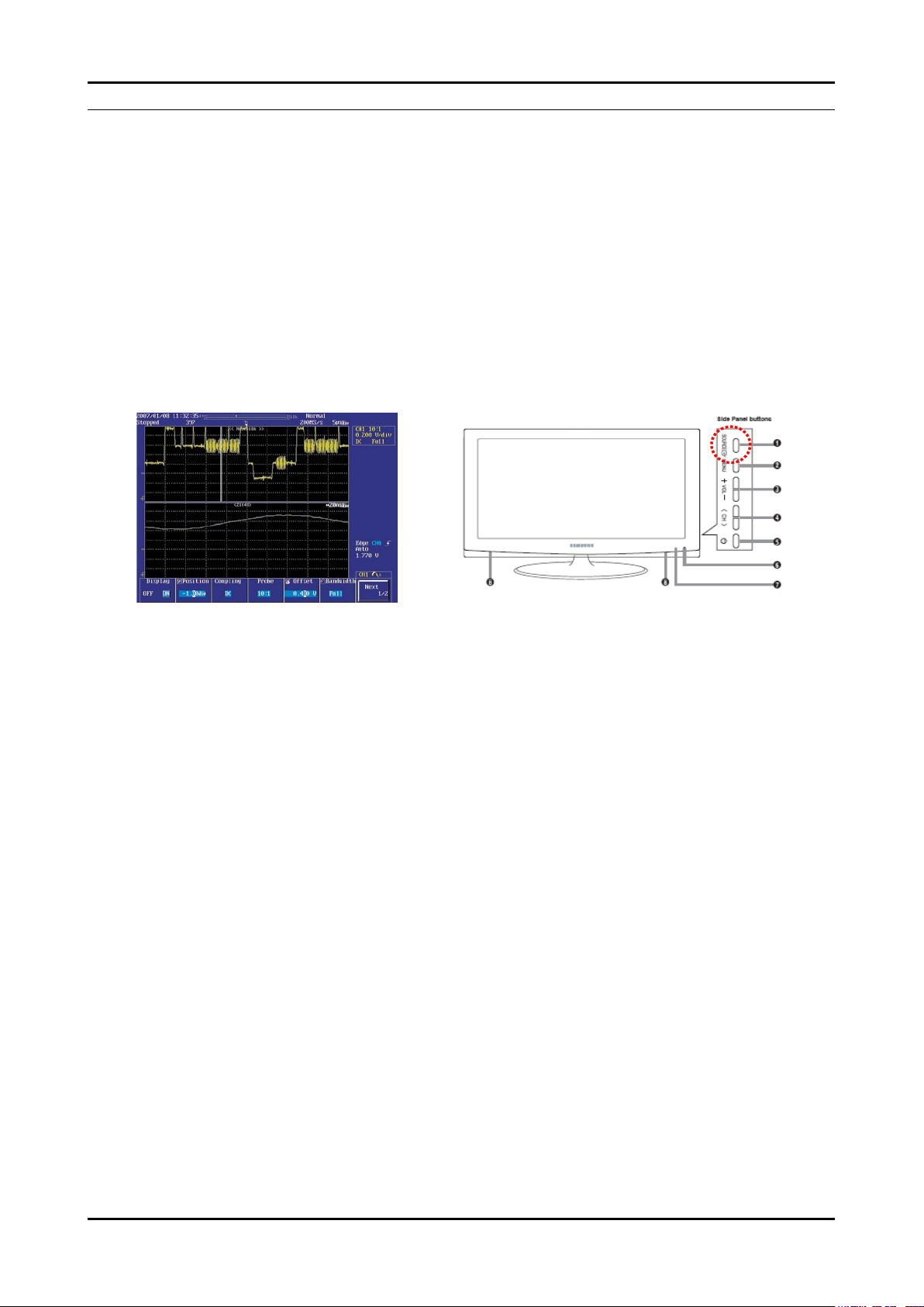
4-1-1. No Power
Symptom
The LEDs on the front panel do not work when connecting the power cord.
The SMPS relay does not work when connecting the power cord.
The units appears to be dead.
-
-
-
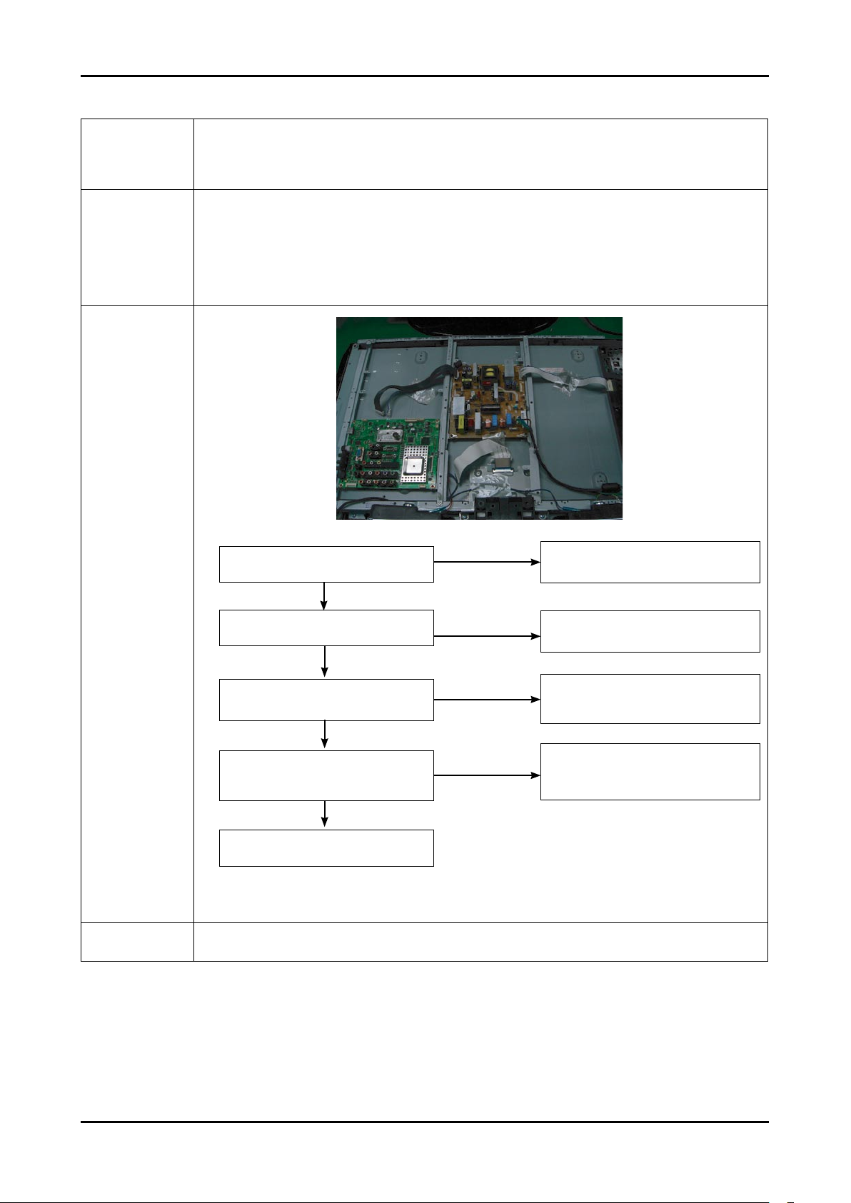
Major
checkpoints
The IP relay or the LEDs on the front panel does not work when connecting the power cord if the cables are
improperly connected or the Main Board or SMPS is not functioning. In this case, check the following:
Check the internal cable connection status inside the unit.
Check the fuses of each part.
Check the output voltage of SMPS.
Replace the Main Board.
-
-
-
-
Diagnostics
Caution
Make sure to disconnect the power before working on the IP board.
Does proper DC A3.3V
appear at C1040?
Check a IC1011
Change a main PCB ass’y
No
Yes
Does proper DC 5V, 3.3V, 1.2V appear
at C1005, C1038, C1063?
No
Yes
LAMP off, power indicator
LED red color?
Yes
No
Check a connection a power cable.
Does proper DC 13V appear at
pin20 of CN1001?
No
Yes
A power is supplied to set?
Change a Assy PCB Power.
Check a IC1006, IC1012.
Change a main PCB ass’y
1
2
3
4

4-3
4. Troubleshooting
4-1-2. No Video (Analog PC signal)
Symptom Audio is normal but no picture is displayed on the screen.-
Major
checkpoints
Check the PC source
Check the M-star
This may happen when the LVDS cable connecting the Main Board and the Panel is disconnected.
-
-
-
Diagnostics
No
PC cable. Change a PC
cable. Change a main PCB ass’y.
No
Does the digital data appear at the
output of LVDS (R6048~6045_FBE)?
Power Indicator is off.
Lamp on, no video.
No
Check a PC source and check
the connection of DSUB cable?
Check a IC6001.
Change a main PCB ass’y
Yes
Check a LVDS cable?
Replace a lcd panel?
Does the signal appear at C5050,
C5049, C5047(R,G,B) of IC5001
Please, Call to Samsung Co. LTD.
Yes
Yes
Input a analog PC signal and
connected cable(DPMS).
Yes
1
Yes
2
3
Caution Make sure to disconnect the power before working on the IP board.
4-4
4. Troubleshooting
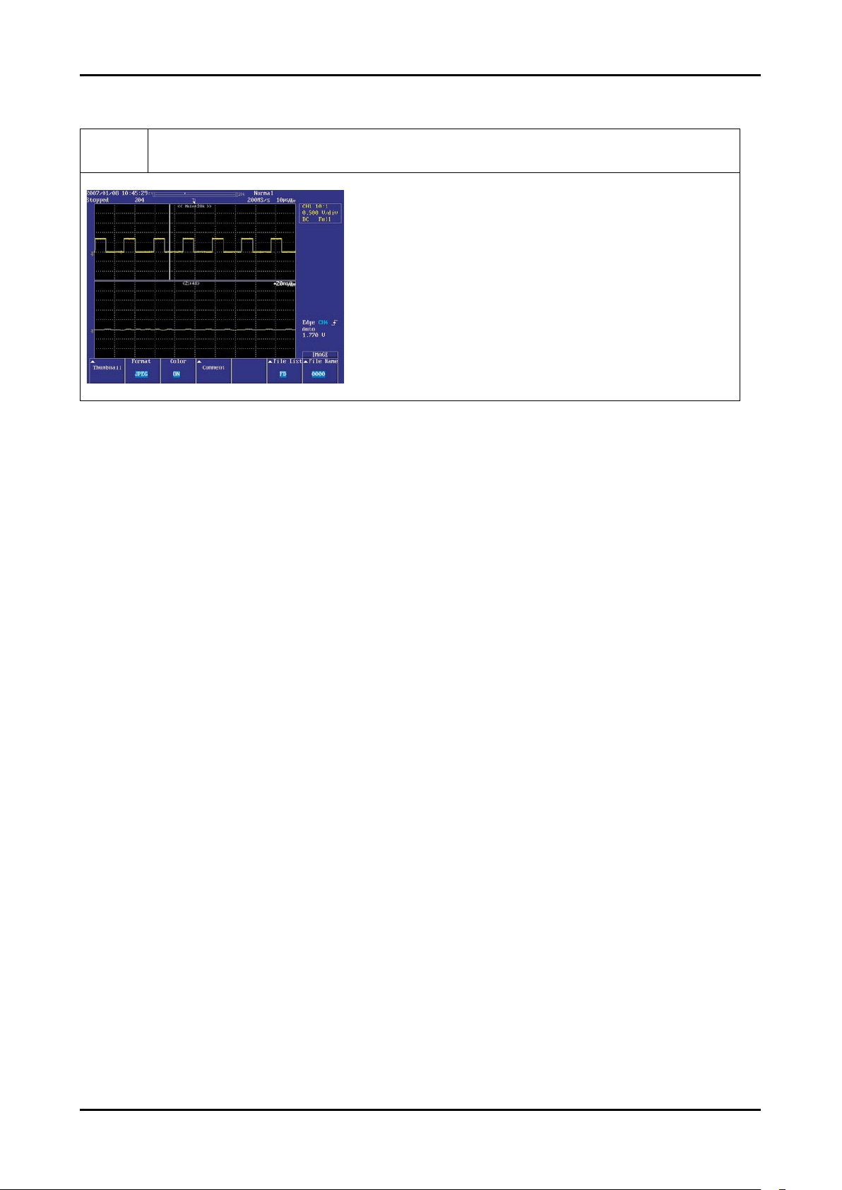
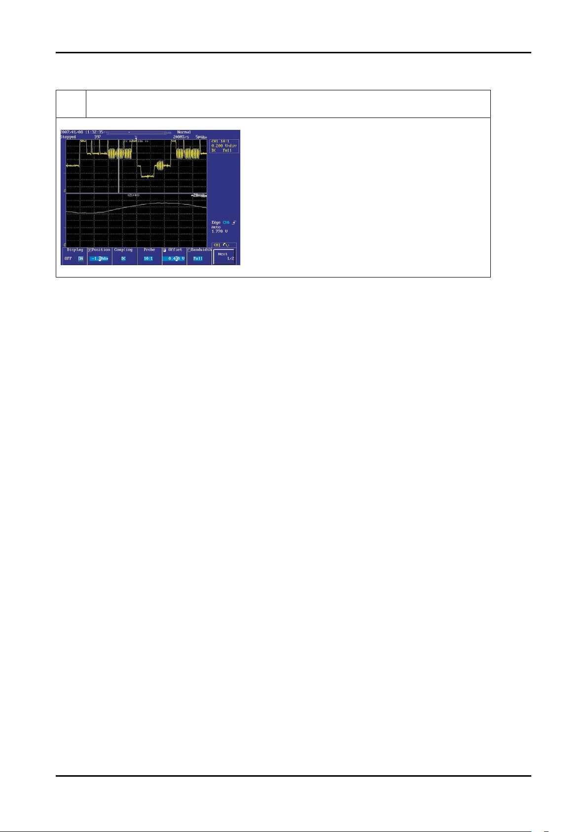
WAVEFORMS
1
R,G,B Output Signal
4-5
4. Troubleshooting
4-1-3. No Video (HDMI - Digital Signal)
Symptom Audio is normal but no picture is displayed on the screen.-
Major
checkpoints
Check the HDMI source
Check the M-star
This may happen when the LVDS cable connecting the Main Board and the Panel is disconnected.
-
-
-
Diagnostics
No
Does the digital data appear at
R5055~5062,R5066~5073?
Power Indicator is off.
Lamp on, no video.
No
Check the connection
of HDMI cable?
Check a IC1402.
Change a main PCB ass’y.
Check a IC1401.
Change a main PCB ass’y.
No
Does the digital data appear at output of
IC5001(R6048~6045_FBE)?
Check the LVDS cable?
Replace the LCD panel?
Please, Contact Tech support
Yes
Yes
Input a HDMI cable.
Yes
Yes
Yes
2
3
1
Caution Make sure to disconnect the power before working on the IP board.
4-6
4. Troubleshooting
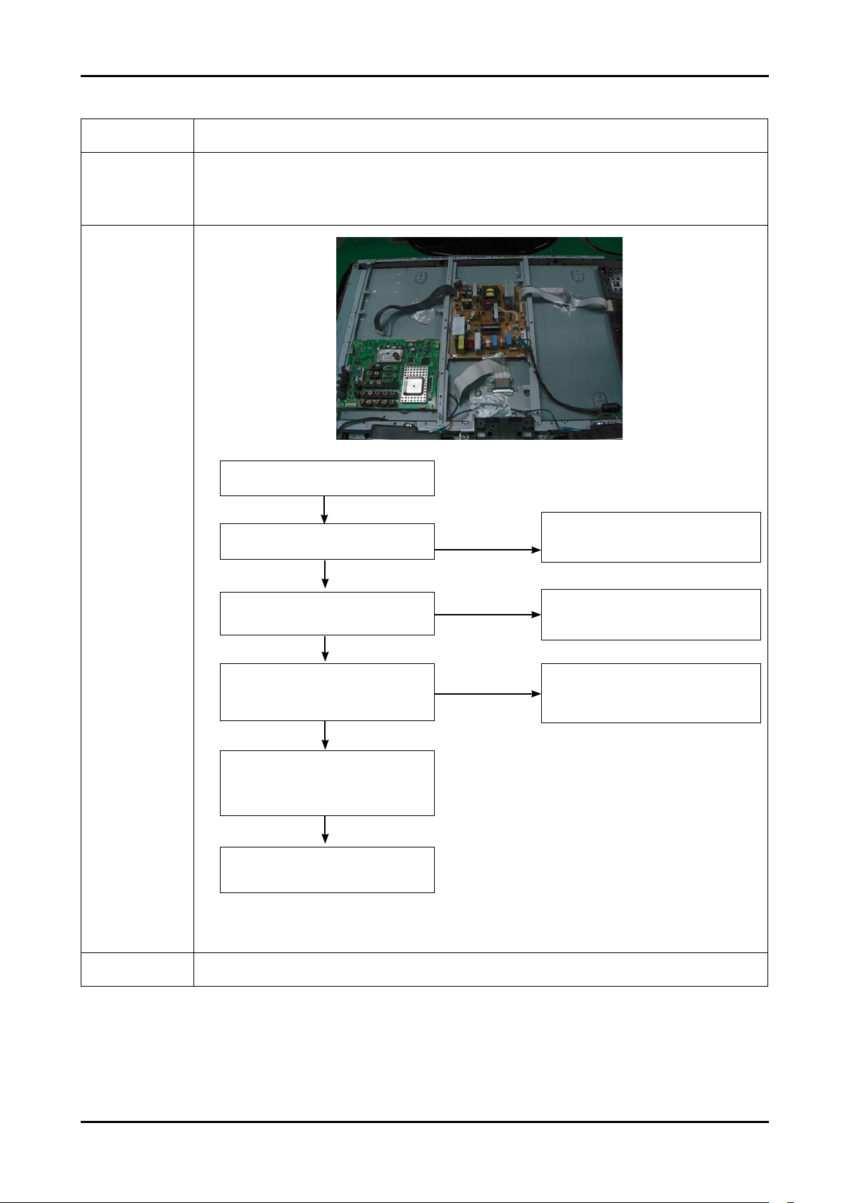
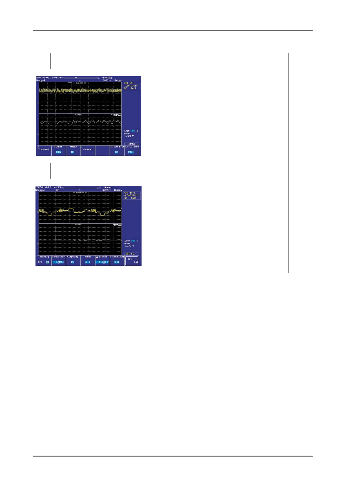
WAVEFORMS
2
Digital Output Data
3
Signal of HDMI(Data)

4-7
4. Troubleshooting
4-1-4. No Video (Tuner_CVBS)
Symptom Audio is normal but no picture is displayed on the screen.-
Major
checkpoints
Check the Tuner CVBS source
Check the M-star
This may happen when the LVDS cable connecting the Main Board and the Panel is disconnected.
-
-
-
Diagnostics
No
Check a B+ voltage (#7of Tuner) 5V,
change a main PCB ass’y.
No
No
Power Indicator is off.
Lamp on, no picure.
Yes
Change a main PCB ass’y.
Does the signal appear at R3235?
[4] Does the signal appear at C5068
of IC5001?
Check the LVDS cable?
Replace the LCD panel?
Please, Call to Samsung Co. LTD.
Yes
Connect the RF cable and
check RF signal.
Yes
Yes
Caution Make sure to disconnect the power before working on the IP board.
4-8
4. Troubleshooting
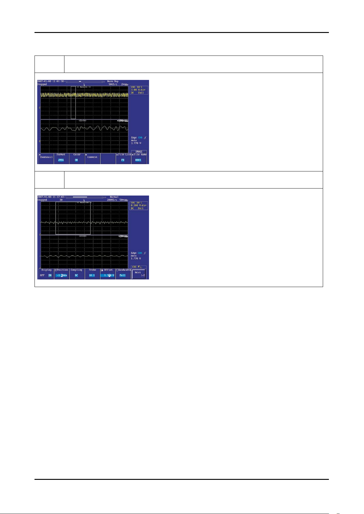
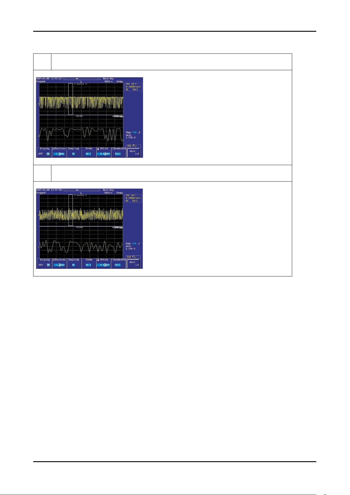
WAVEFORMS
3
CVBS Output Signal
4
Tuner_CVBS Output Signal

4-9
4. Troubleshooting
4-1-5. No Picture (Video_CVBS)
Symptom Audio is normal but no picture is displayed on the screen.-
Major
checkpoints
Check the Video Source
Check the M-star
This may happen when the LVDS cable connecting the Main Board and the Panel is disconnected.
-
-
-
Diagnostics
No
Check a connection harness.
No
Power Indicator is off.
Lamp on, no picture.
Yes
Does the signal appear at C5064
or C5061 of IC5001?
Check a LVDS cable ?
Replcelcd panel?
Please, Call to Samsung Co. LTD.
Yes
Check a A/V cable and video signal.
Yes
1
2
Caution Make sure to disconnect the power before working on the IP board.
4-10
4. Troubleshooting
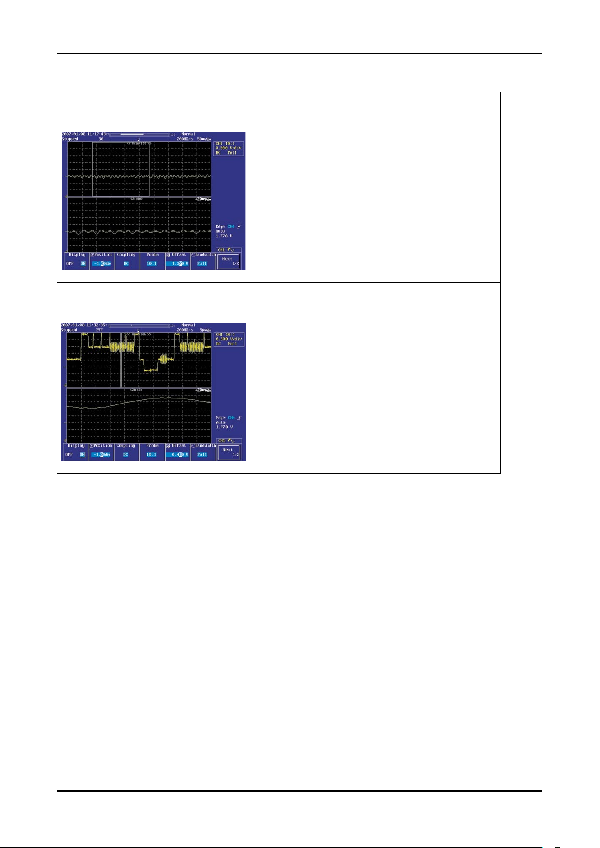
WAVEFORMS
4
CVBS Output Signal

4-11
4. Troubleshooting
4-1-6. No Picture (S-VIDEO_Y,C)
Symptom Audio is normal but no picture is displayed on the screen.-
Major
checkpoints
Check the S-Video_Y,C source
Check the M-star
This may happen when the LVDS cable connecting the Main Board and the Panel is disconnected.
-
-
-
Diagnostics
No
Check a connection harness.
No
Power Indicator is off.
Lamp on, no picure.
Does the Y/C signal appear at
C5062or C5063 of IC5001?
Check a LVDS cable ?
Replcelcd panel?
Please, Call to Samsung Co. LTD.
Yes
Connect the s-video cable.
Operating a video player.
Yes
1
Yes
2
Caution Make sure to disconnect the power before working on the IP board.
4-12
4. Troubleshooting
WAVEFORMS
2
Digital Output Data
5
Analog Signal(Y,C)

4-13
4. Troubleshooting
4-1-7. No Sound
Symptom Audio is normal but no picture is displayed on the screen.-
Major
checkpoints
Check the RF Source
Check the M-star
This may happen when the LVDS cable connecting the Main Board and the Panel is disconnected.
-
-
-
Diagnostics
No
Check a connection harness and
headphone jack./Side AV
Check Sound Processor
IC5001 (M-star)
No
Picture is display, no sound.
Check a B12V Line.
Change a main PCB ass’y
No
Does the signal appear at pin 232, 236,
234,237(I2S_CLK, I2S_SCLK, I2S_
LRCLK, I2S_DATA) of IC1201?
Check the DC 12V
of IC2001?
Change a main PCB ass’y.
No
Does the signal appear at
Pin 47 or 48, 53 or
54(CH1_L, R Sound) And Pin
36 or 37, 30 or 31
(CH2_L, R Sound) of IC2001?
Replace the speaker ass’y?
Yes
Connect a sound cable.
control a volume.
Yes
1
Yes
3
Yes
2
Caution Make sure to disconnect the power before working on the IP board.
4-14
4. Troubleshooting
WAVEFORMS
6
The Signal are Inputed to IC1201
7
The Signal are Inputed to IC1202

4-15
4. Troubleshooting
4-2. Alignments and Adjustments
4-2-1. General Alignment Instuction
Usually, a color LCD-TV needs only slight touch-up adjustment upon installation.
Check the basic characteristics such as height, horizontal and vertical sync.
Use the specied test equipment or its equivalent.
Correct impedance matching is essential.
Avoid overload. Excessive signal from a sweep generator might overload the front-end
of the TV. When inserting signal markers, do not allow the marker generator to distort test result.
Connect the TV only to an AC power source with voltage and frequency as specied on
the backcover nameplate.
Do not attempt to connect or disconnect any wire while the TV is turned on. Make sure
that the power cord is disconnected before replacing any parts.
To protect against shock hazard, use an isolation transformer.
1.
2.
3.
4.
5.
6.
7.
4-16
4. Troubleshooting
4-3. Factory Mode Adjustments
4-3-1 Entering Factory Mode
To enter ‘Service Mode’ Press the remote -control keys in this sequence :
- If you do not have Factory remote - control
MENUINFO MUTE Power on
- If you have Factory remote - control
DISPLAYPICTURE ON FACTORY
- The buttons are active in the service mode.
1. Remote - Control Key : Power, Arrow Up, Arrow Down, Arrow Left
Arrow Right, Menu, Enter, Number Key(0~9)
2. Function - Control Key : Power, CH +, CH -, VOL +, VOL -,
Menu, TV/VIDEO(Enter)
4-3-2 Panel Check
You have to check Panel Maker Because of different adjustments as follows.
First of all, Check the label rating!
1) Label Rating File
- LCD PANEL MARK
A:ACER(AUO) S : SEC C : CMO
* If not printed you could consider S(sec) panel mark.
4-17
4. Troubleshooting
4-3-3 Factory Data
Option Table(Service)
WB Adjust
Information
Advanced Menu
Checksum
T-CRL32MEAM-****
HDCP Success
Month/Day/Year/Hour/MIN/SEC
Option Table(Service)
26” Option
No Item Range Option
1 Factory Reset
2 Country(0x55) Default_0
3 Ready ON/OFF ON
4 Inch Option
19/22/23/26/27/32/37/40
/42/46/50/52/57
26/32/37
5 Dimm Type INT/INT_NEG/EXT_POS/EXT_NEG/EXT/ INT
6 Panel Type
19AM_TN/22AU_TN/22CM_TN/26AM_AG/
26AU_AG/26CM_NG/32AU_AG/32AU_NG/
32CM_NG/32CM_AG/37AU_AG/37CP_AG/
40AU_AG/40AM_AG
26AM_AG/
32AU_AG/
37CP_AG
7 Model Option
Coral/Jade/Tanzanite/Pyrope/Amber
Pyrope_3D/Carnelian/Carnelian_3D
Coral
8 Anynet + ON <-> OFF ON
9 Light Effect ON <-> OFF OFF
10 TTX ON <-> OFF ON
11 TTX List List <-> FLOF FLOF
12 TTX Group
Lang OSD/ W Europe/Russia/Greek/Turek/ Arab/Farsi/
ArabHbrw
Lang OSD
13 Carrier Mute ON <-> OFF OFF
14 High Devi ON <-> OFF OFF
15 Volume Curve EA/EU EA
16 HotPlug ON <-> OFF ON
17 HotPlugCtrl ON <-> OFF ON
18 HotPlugDelay 0 ~ 63 12
19 Auto Power ON <-> OFF ON
20 LNA Menu OFF OFF
21 Hotel Option On <-> Off OFF
22 D.Gamma OFF/0.85/0.88/0.90/0.93/0.95/0.98/ M1/M2/M3/M4 0.98/0.93/0.93
23 PC Ident ON <-> OFF
24 Language Europe/CIS (21 Language) English
25 Ch Table SUWON/SESK/SHE/etc Select Local area
26 DDR Etron
27 Shop Mode ON <-> OFF OFF
28 Nordic OFF
29 Arabic ON <-> OFF ON
30 NT Conversion ON <-> OFF OFF
1.
2.
3.
4.
1.
4-18
4. Troubleshooting
No Item Range Option
31 Control -
WM Calib ON/OFF OFF
EDID Protect ON/OFF ON
Edid Type Coral/P450-50HP/P450-42HP L12_1366_768
EDIE Write Failure/Success L12_1366_768 Succes
WB Data Reset ON <-> OFF OFF
EEPROM Reset
Logic Download ON <-> OFF OFF
32 PDP Filter 42” 3D
33 PDP Group P34A_R3d
34 Spread Spectrum ON/OFF ON
Step1 0~255 30
Step2 0~255 9
Range1 - 0
Range2 - 44
FBE SSC - 5
4-19
4. Troubleshooting
4-4. White Balance - Calibration
4-4-1 White Balance -Calibration
1. Calibration
AV Calibration
Comp Calibration
PC Calibration
HDMI Calibration
4-4-2 Service Adjustment -
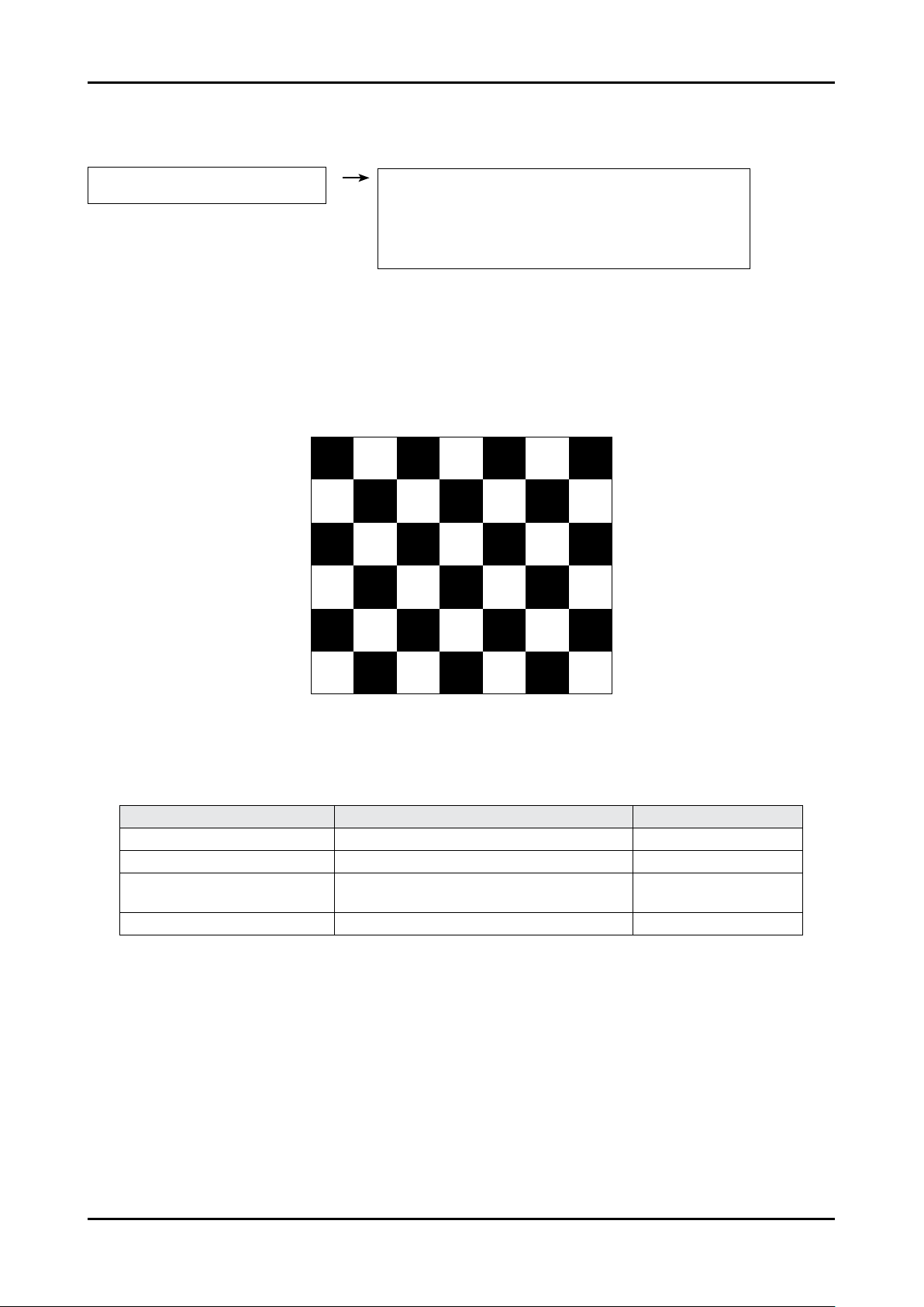
You must perform Calibration in the Lattice Pattern before adjusting the White Balance.
Color Calibration
Adjust spec.
1. Source : HDMI
2. Setting Mode : 1280*720@60Hz
3. Pattern : Pattern #24 (Chess Pattern)
( Chess Pattern )
4. Use Equipment : CA210 & Master MSPG925 Generator
- Use other equipment only after comparing the result with that of the Master equipment.
Input mode Calibration Pattern
CVBS IN (Model_#1) Perform in NTSC B&W Pattern #24 Lattice
Component IN (Model_#6) Perform in 720p B&W Pattern #24 Lattice
PC Analog IN (Model_#21)
Perform in VESA XGA (1024x768)
B&W Pattern #24
Lattice
HDMI IN Perform in 720p B&W Pattern #24 Lattice
<Table 1>

4-20
4. Troubleshooting
Method of Color Calibration (AV)
1) Apply the NTSC Lattice (N0. 3) pattern signal to the AV IN 1 port
2) Press the Source key to switch to “AV1” mode
3) Enter Service mode
4) Select the “Calibration” menu
5) Select the “AV Calibration” menu.
6) In “AV Calibration Off” status, press the “ ” key to perform Calibration.
7) When Calibration is complete, it returns to the high-level menu.
8) You can see the change of the “AV Calibration” status from Failure to Success.
Method of Color Calibration (Component)
1) Apply the 720p Lattice (N0. 6) pattern signal to the Component IN 1 port
2) Press the Source key to switch to “Component1” mode
3) Enter Service mode
4) Select the “Calibration” menu
5) Select the “Comp Calibration” menu.
6) In “Comp Calibration Off” status, press the “ ” key to perform Calibration.
7) When Calibration is complete, it returns to the high-level menu.
8) You can see the change of the “Comp Calibration” status from Failure to Success.
Method of Color Calibration (PC)
1) Apply the VESA XGA Lattice (N0. 21) pattern signal to the PC IN port
2) Press the Source key to switch to “PC” mode
3) Enter Service mode
4) Select the “Calibration” menu
5) Select the “PC Calibration” menu.
6) In “PC Calibration Off” status, press the “ ” key to perform Calibration.
7) When Calibration is complete, it returns to the high-level menu.
8) You can see the change of the “PC Calibration” status from Failure to Success.
Method of Color Calibration (HDMI)
1) Apply the 720p Lattice (N0. 6) pattern signal to the HDMI1/DVI IN port
2) Press the Source key to switch to “HDMI1” mode
3) Enter Service mode
4) Select the “Calibration” menu
5) Select the “HDMI Calibration” menu.
6) In “HDMI Calibration Off” status, press the “ ” key to perform Calibration.
7) When Calibration is complete, it returns to the high-level menu.
8) You can see the change of the “HDMI Calibration” status from Failure to Success.
4-21
4. Troubleshooting
4-4-3 White Balance - Adjustment
3. W/B
(low light) (hight light)
Sub Bright
R offset
G offset
B offset
Sub Contrast
R gain
G gain
B gain
(W/B adjustment Condition refer next page)
4-5. White Ratio (Balance) Adjustment
You can adjust the white ratio in factory mode (1:Calibration, 3:White-Balance).
Since the adjustment value and the data value vary depending on the input source, you have to
adjust these in CVBS, Component 1 and HDMI 1 modes.
The optimal values for each mode are congured by default. (Refer to Table 1, 2)
It varies with Panel’s size and Specication.
1.
2.
3.
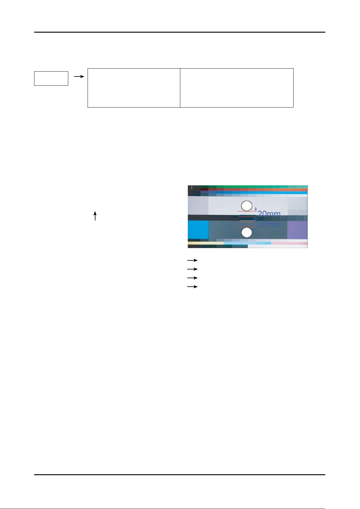
- Equipment : CS-210
- Pattern: MIK K-7256 #92 “Flat W/B Pattern” as standard
- Use other equipment only after comparing the result with
that of the Master equipment.
- Set Aging time : 60min
- Calibration and Manual setting for WB adjustment.
HDMI : Time #6 720P, Pattern #24 Chessboard Calibration Manual adjustment #92 pattern (720p)
COMP: Time #6 720P, Pattern #24 Chessboard Calibration Manual adjustment at #92 pattern (720p)
CVBS: Time #2 PAL, Pattern #24 Chessboard Calibration Manual adjustment at #92 pattern (NTSC)
PC: Time #21 1024*768, Pattern #24 Chessboard Calibration Manual adjustment at #92 pattern (NTSC)
- If nishing in HDMI mode, adjustment coordinate is almost same in AV/COMP mode.
- White Balance Manual Adjustment
4-22
4. Troubleshooting
CA-210
x y Y(L) T(K) + MPCD
CVBS
(NTSC)
H/L 272 287
-
(Sub_CT:145)
11,000 (+10)
L/L 272 287
12.2cd/m
2
(3.52 Ft - Sub_BR:128)
11,000 (+10)
COMP
(720P)
H/L 272 287
-
(Sub_CT:145)
11,000 (+10)
L/L 272 287
12.1cd/m
2
(3.5 Ft - Sub_BR:128)
11,000 (+10)
HDMI
(720P)
H/L 272 287
-
(Sub_CT:145)
11,000 (+10)
L/L 272 287
12.0cd/m
2
(3.5 Ft - Sub_BR:128)
11,000 (+10)
- Adjustment Specication
White Balance : High light (±3), Low light (±5)
Luminance : High light (±0.1Ft/L), Low light (±0.1Ft/L)
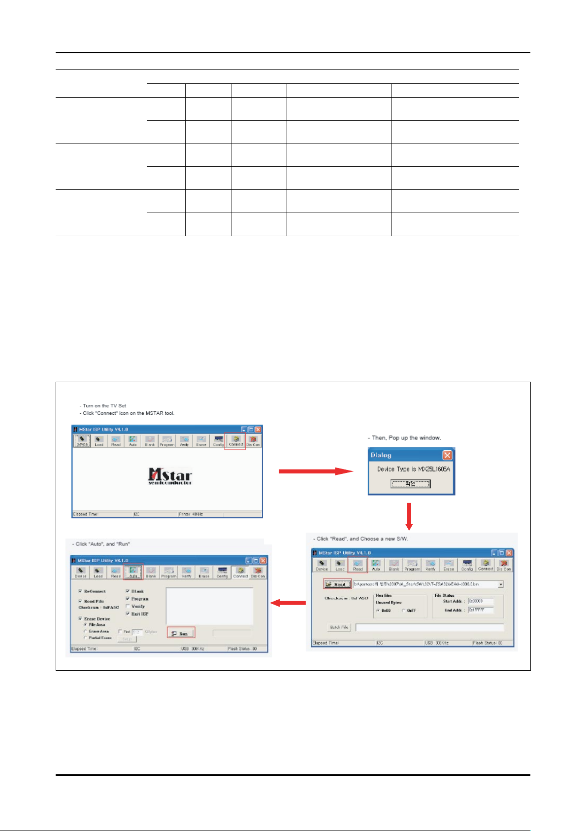
4-6. HOW TO UPGRADE
4-6-1 Software Upgrade (MSTAR ISP Tool)
MSTAR ISP TOOL
4-23
4. Troubleshooting
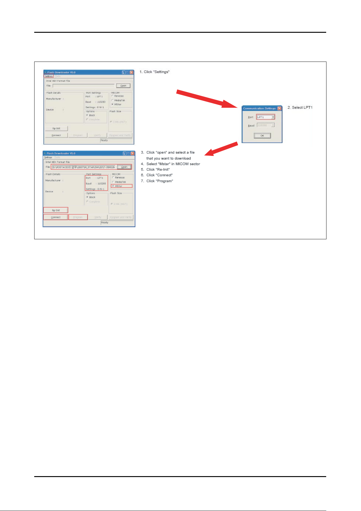
4-6-2 Software Upgrade (Flash Downloader)
Flash Downloader

4-24
4. Troubleshooting
4-6-3 After S/W Upgrade
How to Access Service Mode
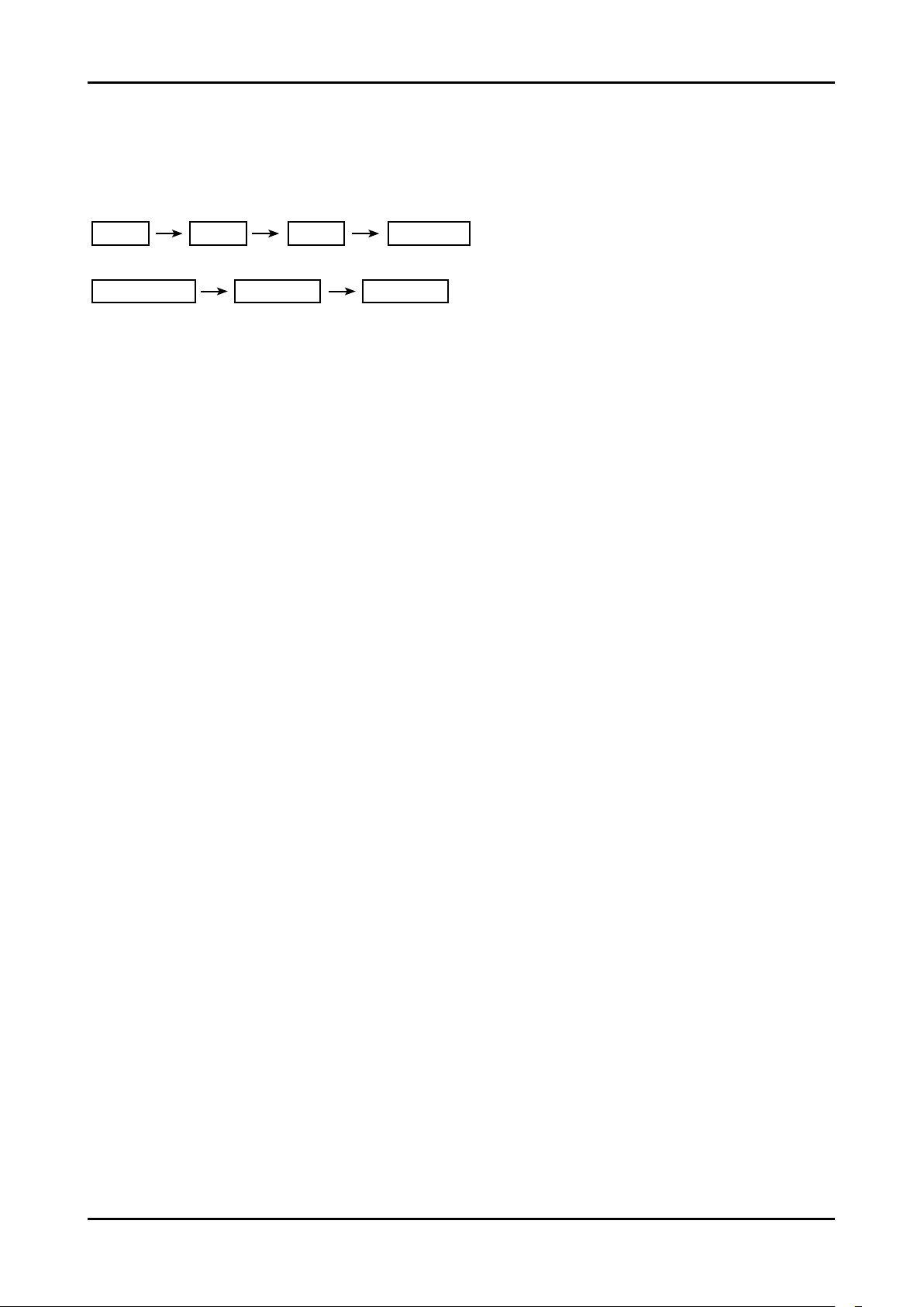
Entering Factory Mode
<Power OFF> → <INFO> → <MENU> → <MUTE> → <Power ON>
Factory Data
Option Table(Service)
WB Adjust
Information
Advanced Menu
If you want to enter here, press “0000”.
How to Initialize.
Click “1. Option Table(Service)” → “Factory Reset” in Factory Menu.
You can make every setting in Factory Initial Status.
1.
2.
3.
4.
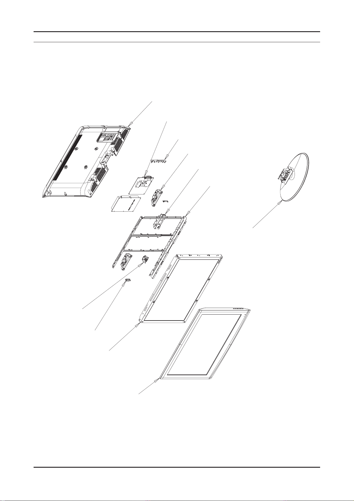
5. Exploded View & Part List
5-1. LA26A450C1X / LA26A350C1X Exploded View
M0013
M0014
M0254
T0175
M0115
T0447
5. Exploded View & Part List
M0125
M0027
M0146
M0215
T0003
5-1
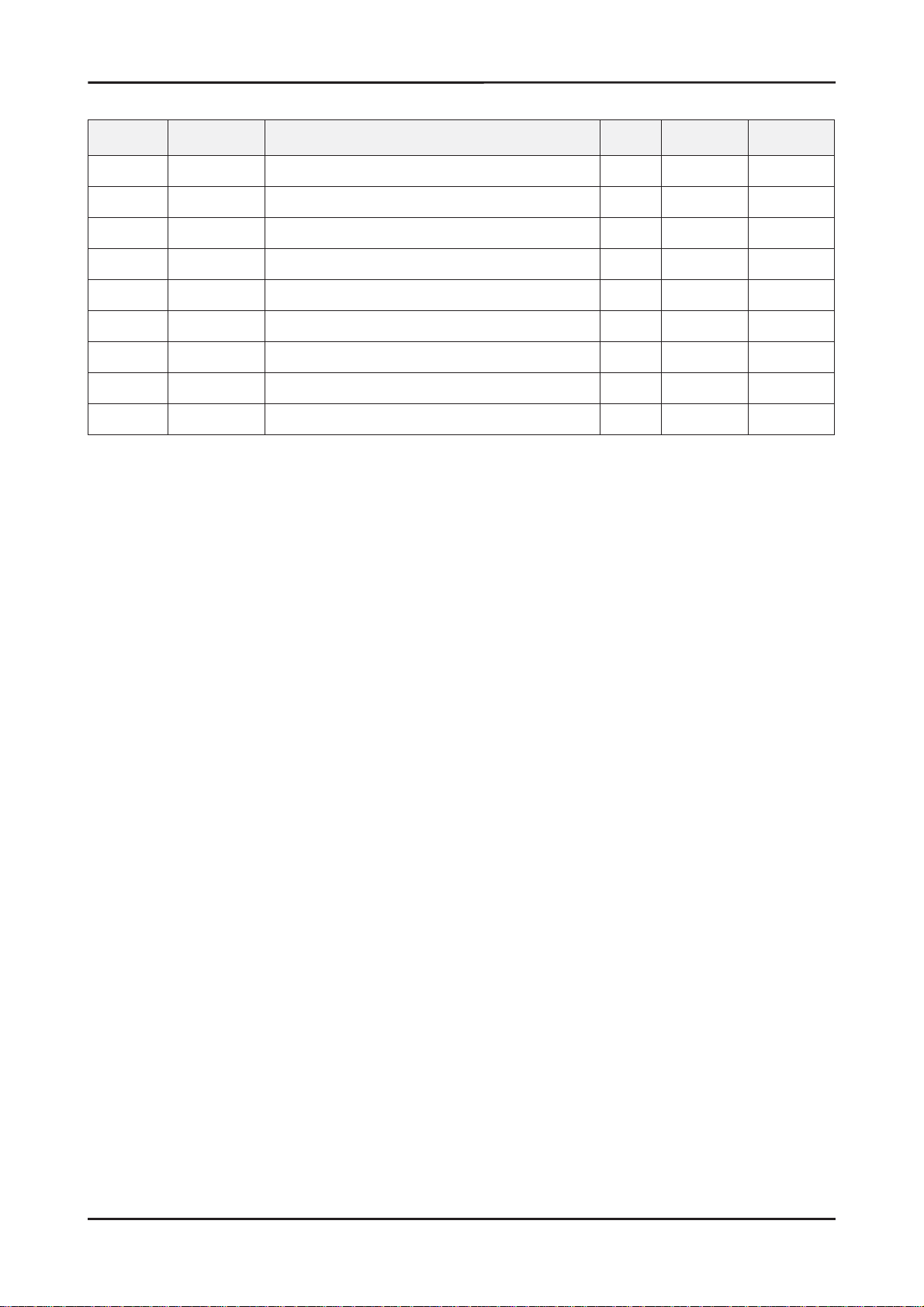
5. Exploded View & Part List
5-1-1. LA26A450C1X / LA26A350C1X Parts List
Location No. Code No. Description & Specifi cation Q’ty S.A/S.N.A Remark
T0003 BN96-06783L ASSY COVER P-FRONT;26L450,SO,ABS+PMMA,HB 1 S.A
M0215 BN07-00528A LCD-PANEL;LTF260AP01 1 S.A
T0175 BN96-06822C ASSY SPEAKER P;8ohm,CORAL,LCD 26”,5W,4pi 1 S.A
T0447 BN96-06957A ASSY BRACKET P-PANEL;26L450,AMLCD,,SECC, 1 S.N.A
M0014 BN94-01713A ASSY PCB MAIN;LA26A450C1X* 1 S.A
M0115 BN61-02947A BRACKET-STAND LINK;JASMINE 32”,SECC,T1.6 1 S.A
T0101 BN61-03346A BRACKET-WALL;LCD TV ,SECC,T1.2 4 S.N.A
M0013 BN96-07210A ASSY COVER P-REAR;26L450,SO,HIPS,HB,BK50 1 S.A
M0027 BN96-06463F ASSY STAND P-BASE;22,26L450,ABS+PMMA,HB, 1 S.A
5-2
 Loading...