

Page 1
Disassembly and Assembly Instructions
7.
Disassembly
7-1.
1 2
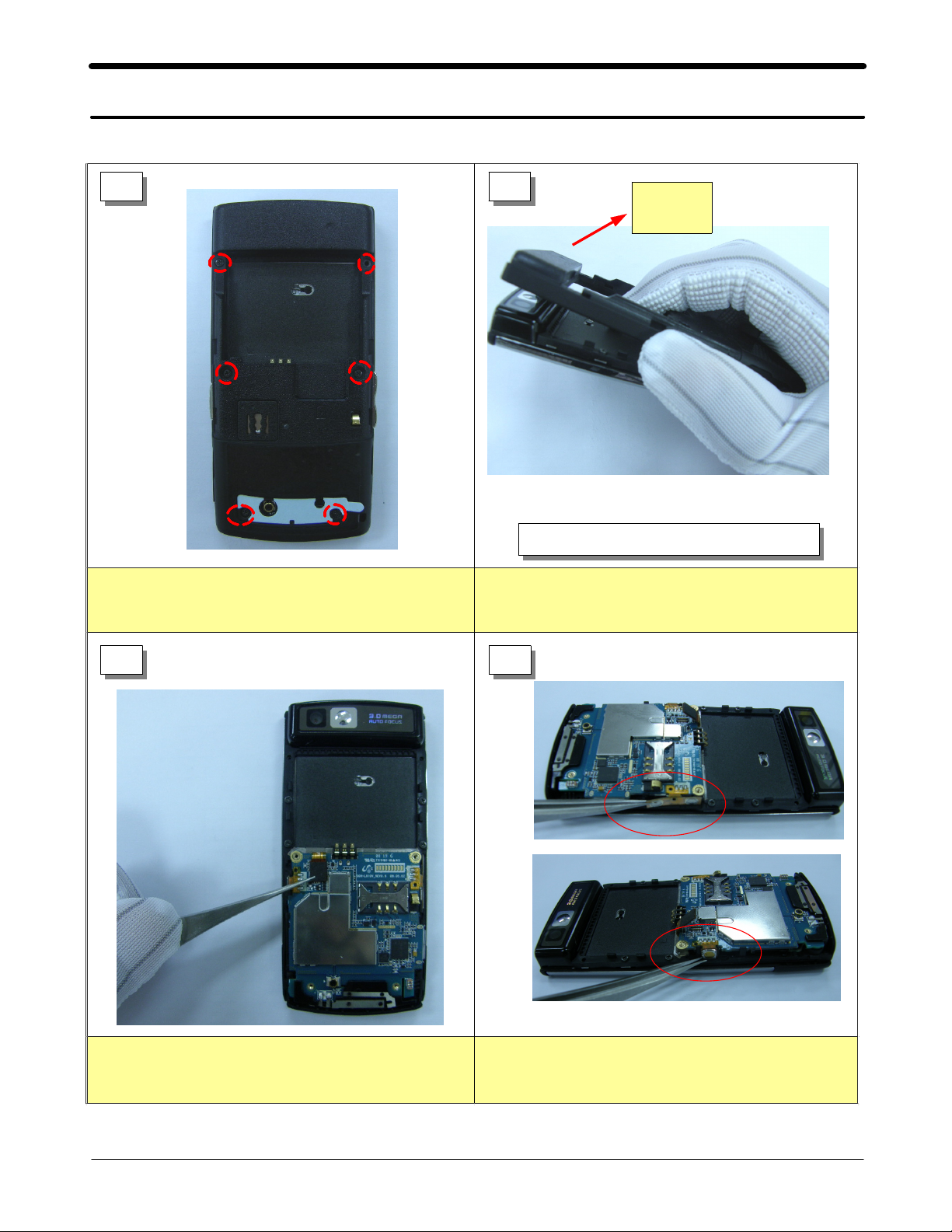
Unscrew the6points of the REAR.
1)
Direction
of force
Be care of the scratch.
1)
Detach the REAR from slide ass`y.
1)
3 4
Detach the FPCB connector by using the pincette.
1)
Detach the volume key from the molding.
1)
Detach the camera key from the molding.
2)
7-1
SAMSUNG Proprietary-Contents may change without notice
This Document can not be used without Samsung's authorization
Page 2
Exploded View and Parts List
5 6
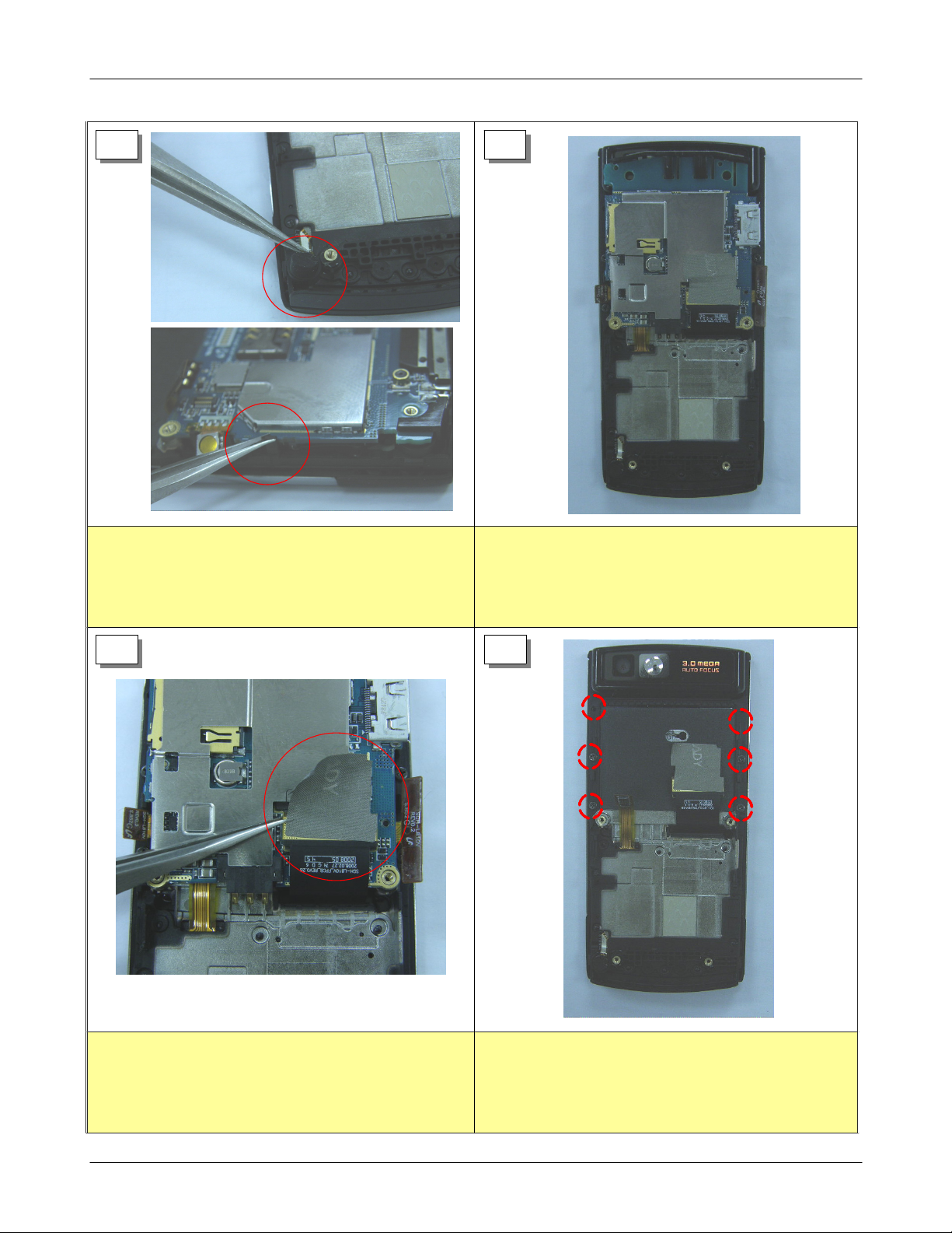
Detach the mic from holder by using pincette.
1)
Detach the PBA, pushing the rib to the left side.
2)
7 8
Put the PBA upside down
1)
Detach the electric tape by using pincette.
1)
Detach the connector from the PBA.
2)
SAMSUNG Proprietary-Contents may change without notice
This Document can not be used without Samsung's authorization
Unscrew the6points on the LOWER.
1)
7-2
Page 3
Exploded View and Parts List
9
Detach the electric tape by using pincette.
1)
10
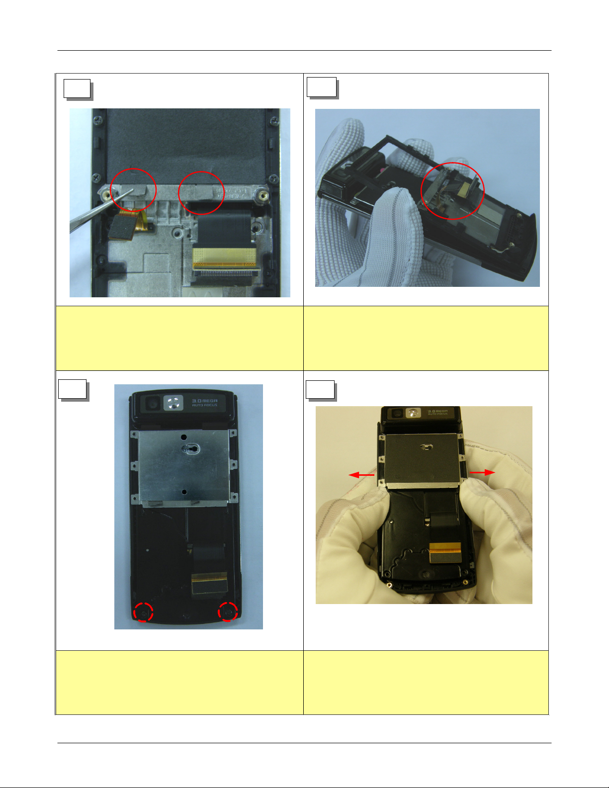
Take out the FPCB connector through the hole.
1)
Be careful.
Detach the front from the Upper Ass`y.
2)
11
12
Detach the2points on the LOWER bottom.
1)
SAMSUNG Proprietary-Contents may change without notice
This Document can not be used without Samsung's authorization
Detach the LOWER from the UPPER.
1)
7-3
Page 4

Exploded View and Parts List
13
Detach the module from top side.
1)
Detach the LCD ass`y from the lower.
2)
Be careful.
14
The END.
1)
7-4
SAMSUNG Proprietary-Contents may change without notice
This Document can not be used without Samsung's authorization
Page 5

7-2.
Exploded View and Parts List
Assembly
1
Attach the LCD ass`y to the LOWER.
1)
Be careful of the bottom side rib.
2)
2
Attach the LOWER to the UPPER.
1)
3
Screw the2points on the LOWER bottom side.
2)
4
Put in the FPCB connector through the hole.
1)
Be careful of demage.
7-5
SAMSUNG Proprietary-Contents may change without notice
This Document can not be used without Samsung's authorization
Page 6

Exploded View and Parts List
5
Attach the electric tape matching the shape.
1)
Screw the6point.
2)
6
Attach the non-elctric tape to the LOWER.
1)
7
FPCB
1)
2)
커넥터를 결합한다
Attach the electic tape to the top of connector.
Attach the FPCB connector.
.
8
Turn upside down the PBA
1)
Attach the FPCB connector.
2)
Attach the key FPCB(volume key, camera key) to the
3)
molding.
7-6
SAMSUNG Proprietary-Contents may change without notice
This Document can not be used without Samsung's authorization
Page 7

9 10
Be careful of scratch.
1)
Exploded View and Parts List
Attach the REAR to the slide ass`y.
1)
Screw down six points.
1)
The END.
2)
7-7
SAMSUNG Proprietary-Contents may change without notice
This Document can not be used without Samsung's authorization
 Loading...