

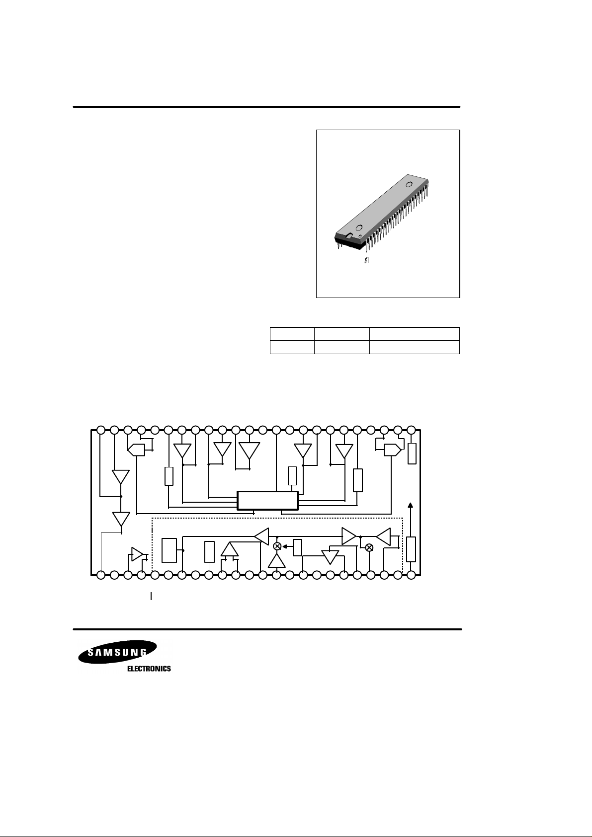
KA8601C SPEAKER PHONE WITH SPEECH NETWORK
BNM : Back Noise Monitor
ORDERING INFORMATION
INTRODUCTION
The KA8601C is a monolithic integrated circuit for use in high performance speaker phone system.
The KA860lC consists of speaker phone and speech network. Speaker
phone includes attenuators, amplifiers, level detectors, attenuator
control, hybrid amplifiers, regulator and AGC circuit. Speech network
includes transmit amp, receive amp, voltage regulator for dialer, side
tone control, and line equalizer.
FEATURES
• Speaker Phone
- Low Operating Voltage (3.0 ~ 6.5V)
- High Attenuator Gain Range (52dB)
- Improved Sensitivity (Four-point Signal Sensing)
- Chip Disable for Active or Standby Operation
- Microphone Amp Gain set by External Components
• Speech Network
- Low Operating Voltage (1.5V : speech)
- Regulated Voltage for Dialer (Typically 3.3V)
- Transmit, Receive, Side Tone Gains set by
External Components
- Mute Input for DTMF Dialing
KA8601C 48-SDIP-600
BLOCK DIAGRAM
TX1
RX1
DTO48
GND
44
RX1
PD RXDETI
43
42
ATT
ATT
RXO
RXI
DTI
47
46
45
DETO
41
DETO
40
TX1
DETI
39
MICO
38
MICIMTVC
36
37
35
48-SDIP-600
Device Package Operating Temperature
- 25°C ~ + 75°C
TX2
RX2
RX2
CT
DETI
34
33
DETO
32
DETO
31
TX2
DETI
30
PD TXVB
29
ATT
ATT
DD
TXI
TXO
V
28
27
26
25
hybrid
amp 1
SPEAKER PHONE PART
hybrid
amp 2
1
2
3
DTO+CDFI
RX
FILTER
4
4
FO
Attenuator
5
MT
BNM
DC level
shift
6
VI
SPEECH NET-
WORK PART
8
7
VL
LC
level
detector
1.7Vreg
9
VR
10
MICI-
11
MICI+
mic
amp
12
GND
mic
amp
ATTENUATOR
CONTROLLER
TX
13
MICO
14
TXI
amp2
TX
15
AGC
AGC
AGC
amp1
level
detector
REC
amp
16
17
RXO+NCNC
BNM
sidetone
amp
20
18
19
RXI
RXO-
21
SUM
RXO
TX
Attenuator
RX
22
ZB
amp
3.3Vreg
POWER
23
24
CC
V
MS
KA8601C SPEAKER PHONE WITH SPEECH NETWORK
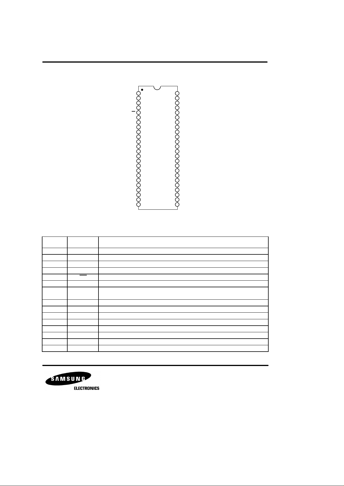
PIN CONFIGURATION
1
DTO+
2
CD
3
FI
4
FO
5
R4
6
V
I
7
VL
8
L
C
9
VR
10
MICI-
MICI+
GND
MICO
AGC
RXO+
RXO-
RXI
RXO
SUM
V
KA8601C
11
12
13
14
TXI
15
16
17
NC
18
NC
19
20
21
22
Z
B
23
MS
24
CC
48
47
46
45
44
43
42
41
40
39
38
37
36
35
34
33
32
31
30
29
28
27
26
25
Fig. 2
PIN DESCRIPTION
Pin No Symbol Description
1 DTO+ Output of the second hybrid amplifier.
2 CD Chip Disable. A logic low (<0.8V) sets normal operation.
3 FI Filter input.
4 FO Filter output.
5 MT Mute input. A logic “1” sets normal speech mode.
6 V
7 V
8 L
9 V
I
L
C
R
10 MICI- Inverting differential input to the mic amp.
11 MICI+ Non-inverting differential input to the mic amp.
12 GND Ground pin for the speech network.
13 MICO Mic amp output.
14 TXI Input to the TX amp from the Mic amp.
15 AGC Loop current sensing input.
A resistor connected from this pin to VSS sets the AC terminating impedance.
Power supply for the speech network. Supply voltage is derived from loop current.
TX amp output operates on this pin.
Resistor at this pin set the DC characteristics of the circuit.
A 1.7 volt regulated output which can be used to bias the mic.
DTODTI
ATT
RXO
RXI
ATT
GND
PD
RX
DETIRX1
DETO
DETOTX1
DETI
TX1
MICO
MICI
MT
V
C
CT
DETIRX2
DETO
DETO
DETI
TX2
PD
TX
V
B
TXI
ATT
TXO
ATT
V
DD
RX1
RX2
TX2

KA8601C SPEAKER PHONE WITH SPEECH NETWORK
PIN DESCRIPTION (continued)
Pin No Symbol Description
16 RXO+ RX amp non-inverting differential output.
17 NC No connection.
18 NC No connection.
19 RXO- RX amp inverting differential output.
20 RXI Input to the RX amp.
21 RXO
22 Z
SUM
B
23 MS
24 V
25 V
26 TXO
27 TXI
28 V
29 PD
CC
DD
ATT
ATT
B
TX
30 DETITX2 Input to the TX level detector on the mike/speaker side.
31 DETOTX2 Output of the TX level detector on the mike/speaker side.
32 DETORX2 Output of the RX level detector on the mike/speaker side.
33 DETIRX2 Input to the RX level detector on the mike/speaker side.
34 C
35 V
T
C
36 MT
37 MICI Input and summing node of the mic amp.
38 MICO Output of the mic amp is set by external resistors.
39 DETTX1 Input to the TX level detector on the line side.
40 DETOTX1 Output of the TX level detector on the line side.
41 DETORX1 Output of the RX level detector on the line side.
42 DETIRX1 Input to the RX level detector on the line side.
43 PD
RX
44 GND Ground pin for the speaker phone part.
45 RXI
46 RXO
ATT
ATT
47 DTI Input and summing node of the mic amp.
48 DTO - Output of the first hybrid amplifier.
Summed output of the RX current amp.
Input to the RX current amp.
Mode select input. A logic “1” → pulse dialing, A logic “0” → tone (DTMF) dialing.
A supply voltage pin for the speaker phone part.
A regulated 3.3 volt output for an external dialer.
Output of the TX attenuator.
Input to the TX attenuator.
This voltage is a system AC ground, and biases the volume control. A filter cap is required.
An RC at this pin sets the time constant for the TX background monitor.
This pin sets the response time for the circuit to switch modes.
Volumn control input.
Mute input. A logic low (<0.8V) sets normal operation. A logic high (>2.0V) mutes the
mic amp.
A RC at this pin sets the time constant for the RX background monitor.
Input to the RX attenuator and dial tone detector.
Output of the RX attenuator.
 Loading...