

Samsung KA7305 Datasheet
KA7305 B/W CCD PROCESSOR
ORDERING INFORMATION
GENERAL DESCRIPTION
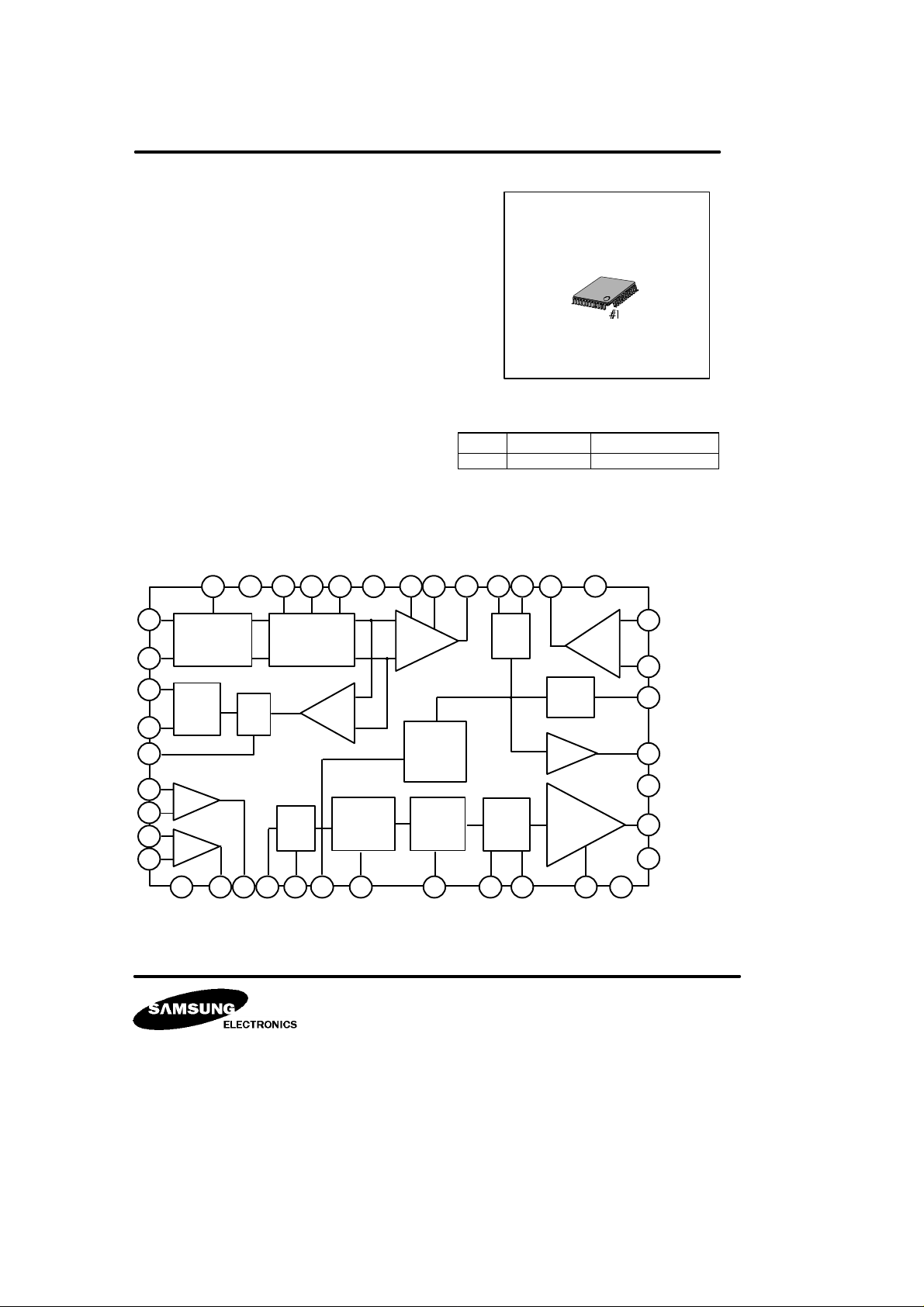
The KA7305 is a monolithic integrated circuit for B/W CCD
camera 1 chip signal processor.
It contains functional block from CDS to video driver and
2 comparators for EE mode. Also, it performs a low power
onsumption and a small dimension of set implementation
by decreasing external parts as a 1 chip.
FEATURES
* 5 Steps sample & hold.
* 4 dB ~ 32 dB AGC gain control.
* Built in 2 comparators for EE mode control.
* EE mode WND / BLK selectable.
* Gamma γ = 0.45 / Linear output separation.
* Built in OP-AMP for AGC loop.
* 3 Mode set-up control.
* 2 Mode white / clip control.
* 75 Ohm video driver & sag compensation.
BLOCK DIAGRAM
Device Package OperatingTemperature
KA7305 48-QFP-0707
48-QFP-0707
-20°C ~ +75°C
4044
OB
CLP
24 25
LUM
DET
LIN
VIDEO
DRIVE
6
OP
AMP
38
+
-
39
37
17
33
26
19
36
OB
CLP
4
SAMPLE
& HOLD
OB
CLP
20 43
3 21
EE
AMP
18 21
48
+
-
SET-UP
CONTROL
+
AGC
AMP
-
GAMMA
r=0.45
WHITE
CLIP
464241
22 23
45
LUM &
SYNC
MIX
9
7
DUMMY
CLAMP
8
34
WIN/
BLK
16
35
32
+
COMP
-
31
30
+
COMP
-
29
27 28
5
KA7305 B/W CCD PROCESSOR
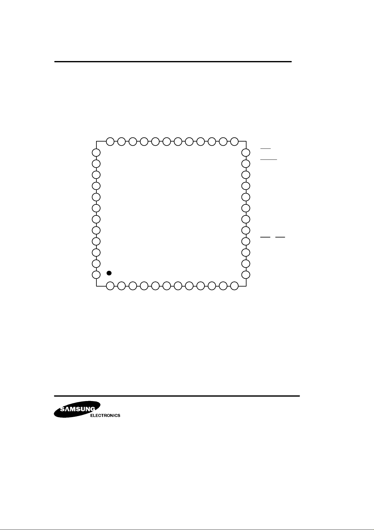
VCC1
SHP1
SHD
SHP2
GND1
GND2
PG
DATA
CLP3
N.C
N.C
N.C
PIN CONFIGURATION
DET OUT
OP(+)
OP(-)
OP OUT
AGCONT
AGCMAX
CLP1
CLP
IN
AGC OUT
N.C
VCC2
37
38
39
40
41
42
43
44
45
46
47
48
VCC3
IRIS CLP
3536
IRIS OUT
34
CP1(+)
GND4
CP1(-)
313233
CP2(+)
30
CP2(-)
KA7305
B/W CCD PROCESSOR
2
1
3
4
6
5
7 8
9
EEI
10
EE2
VIDEO OUT
2526272829
12
11
SAG
24
23
22
21
20
19
18
17
16
15
14
13
BLK
SYNC
W/C
SET-UP
VIDEO IN
GND3
OUT
LINEAR
WIN/BLK
N.C
N.C
N.C
KA7305 B/W CCD PROCESSOR
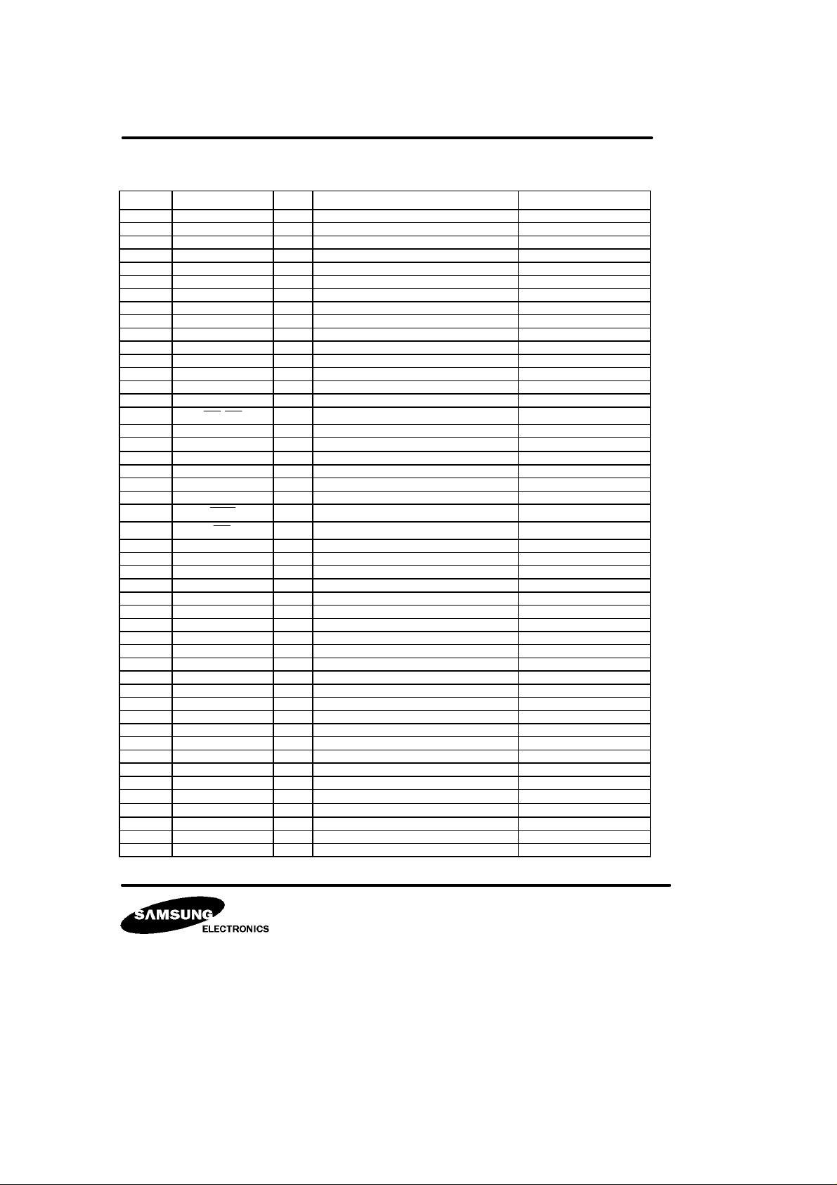
PIN DESCRIPTION
No Symbol I/O Description Remark
1 VCC1 - Power supply
2 SHP1 I Precharge sample & hold pulse Active high
3 SHD I Data sample & hold pulse Active high
4 SHP2 I Precharge sample & hold pulse Active high
5 GND1 - Ground
6 GND2 - Ground
7 PG I CCD signal input
8 DATA I CCD singal input
9 CLP3 I Dummy clamp pulse Active high
10 N.C - No connection
11 N.C - No connection
12 N.C - No connection
13 N.C - No connection
14 N.C - No connection
15 N.C - No connection
16 WIN/BLK I Window/Blank pulse Active high
17 LINEAR O Linear out
18
19 GND3 - Ground
20 VIDEO IN I Video driver input signal
21 SET-UP I Set - up level control
22 W/C I White - clip level control
23 SYNC I Composite sync pulse
24 BLK I Composite blank pulse
25 SAG I Sag compensation
26 VIDEO OUT O Composite video signal output
27 EE2 O EE more comparator output 2
28 EE1 O EE more comparator output 1
29 CP2(-) I EE more comparator2 - input
30 CP2(+) I EE more comparator2 + input
31 CP1(-) I EE more comparator1 - input
32 CP1(+) I EE more comparator1 + input
33 GND4 - Ground
34 IRIS OUT O IRIS detect output
35 IRIS CLP - IRIS clamp
36 VCC3 - Power supply
37 DET OUT O AGC detect output
38 OP(+) I AGC OP AMP input (+)
39 OP(-) I AGC OP AMP input (-)
40 OP OUT O AGC OP AMP output
41 AGCONT I AGC gain control
42 AGCMAX I AGC maximum gain control
43 CLP1 I Optical black level clamp pulse Active high
44
45
46 AGC OUT O AGC output signal
47 N.C - No connection
48 VCC2 - Power supply
ϒ OUT
ϒ CLP
ϒ IN
O Gamma out
- Gamma clamp
I Gamma input
 Loading...