

Page 1

ITP-5012L
IP Phone
User Guide
Page 2

CLASS B Digital device or Peripheral
g
g
g
g
g
g
This equipment has been tested a nd found to comply with the limits
for a Class B di
EN55022, and EN61000, Part 15 of the FCC Rules and Australian
Standard AS/NZS3548.
These limits are desi
harmful interference in a residential installation. This equipment
enerates, uses and can radiate radio frequency en ergy and, if not
installed and used in accordance with the instructions, may cause
harmful interference to radio communications.
However, there is no
particular installation. If this equipment does cause harmful
interference to radio or television reception, which can be
determined by turnin
encoura
following measures:
- Reorient or relocate the receiving antenn a .
- Increase the separation between the equipment and receiver.
- Connect the equipment into an outl et on a circuit different from
- Consult the dealer or experienced radio TV technician for
help.
ed to try to correct the interf erence by one or more of the
that to which the receiver is connected.
ital device, pursuant to International Standaards
ned to provide reasonable protection against
uarantee that interference will not occur in a
the equipment off and on, the user is
Page 3

Page 4

ii
COPYRIGHT
This manual contains the information, which is proprietary to SAMSUNG Electronics Co., Ltd.
and is protected by copyright. No information contained herein may be copied, translated,
transcribed or duplicated for any commercial purposes or disclosed to third parties in any form
without the prior written consent of SAMSUNG Electronics Co., Ltd.
TRADEMARKS
ITP-5012L is a registered trademark of SAMSUNG. Product names mentioned in this document
may be trademarks and/or registered trademarks of their respective companies.
Please read this Guide before using the ITP-5012L IP phone, and follo w the instructions to use the ITP-5012L I P
phone safely and correctly .
SAMSUNG reserves the right to change information contained in this guide for the system improvement,
standardization and other technical reasons without prior notice. For further information on the updated manual,
contact your Samsung Authorised reseller.
©2003 SAMSUNG Electronics Co., Ltd. All rights reserved.
Page 5
ABOUT THIS GUIDE
This is a User’s guide provides instructions for the use of Samsung’s latest ITP5012L large LCD IP Phone that can be used in conjuction with the Samsung
Enterprise IP Solutions System.
Please take the time to study this guide to become familiar with the operation of
your ITP 5012L phone and the benefits this new IP technology can provide. Keep
this guide handy. You may need to look up instructions for infrequently used
features.
Learning to use the power of the ITP 5012L phone will simplify your
communication needs.
Conventions
The following conventions are used in this document to assist your understanding
of and to get the most out of your Samsung ITP 5012L pphone.
iii
Warning
Indicates a potentially hazardous situation, which if not avoided, could result in
serious injury or major damage to your ITP 5012L phone.
Caution
Indicates a potentially hazardous situation, which if not avoided, may result in
injury or damage to your ITP 50 12L phone t. It may also be used to alert against
unsafe practices.
Note
Indicates additional information fo r refe re nce
Page 6
iv
SAFETY CONCERNS
For product safety and correct operation, the following information must be given
to the operator/user and shall be read before the installation and operation.
Symbols
Caution
Indication of a general caution
Restriction
Indication for a prohib i ted action when using the product
Instruction
Indication for a required action
CAUTIONS
Page 7
The ITP-5012L IP phone is supplied with a A C power adapter and this
adaptor must be used.
If an alternative power adapter is used for, the ITP-5012L IP phone this may
result in serious damage a nd vo ids the w arra nty.
Be careful not to connect the network LAN cable to the PC connector of
the ITP 5012L phone.
If the LAN network cable is connected to the PC connection port of the phone ,
both telephone and PC communication s will be lost.
Avoid placing objects containing water near the IP phone.
Do not put objects that contain water such as vases, cups, cosmetics , and
medicines, near the IP phone. Moisture in the IP phon e may cause fire and
electric shocks.
v
Do not install the IP phone in the following locations:
- In direct sunlight or near a heater
- Areas of high humidity or flowing water
- Areas with temperature extremes or volatile changes in temperature.
-Dusty or dirty areas
Use a soft dry cloth to clean the IP phone.
Do not use chemical solvents like wax, benzene, alcohol, thinner, mosquito spray,
aerosol, lubricant, and detergent to clean your ITP-5012L phone.
Do not separate, repair nor remodel the IP phone arbitrarily
Page 8

vi
If a repair is needed , please call your Auth orised Samsung Service Agent.
If items are missing or damagedf ound when you opened the phone package,
please contact your Authorised Samsung Reseller where you purcha se d the
phone to ask for information.
TABLE OF CONTENTS
ABOUT THIS GUIDE.....................................................................................................iii
Conventions ......................................................................................................................iii
SAFETY CONCERNS.................................................................................................. iv
Symbols ........................................................................................................................... iv
Chapter1 Things You Should Know......................................................................... 1-1
Introduction to ITP-5012L ....................................................................................................1-1
Main Features ................................................................................................................ 1-1
Front Panel of the ITP-5012L...............................................................................................1-2
Dial Button...................................................................................................................... 1-2
Select Button..................................................................................................................1-3
Volume Button ............................................................................................................... 1-3
Screen Button ................................................................................................................1-3
Conference Button ......................................................................................................... 1-3
Transfer Button ..............................................................................................................1-3
Hold Button ....................................................................................................................1-4
Speaker Button ..............................................................................................................1-4
Navigation Button...........................................................................................................1-4
LCD Panel and Screen Configuration............................................................................ 1-6
Scroll Key .......................................................................................................................1-7
Microphone .................................................................................................................... 1-7
Page 9

vii
Status Indicator .............................................................................................................. 1-7
Transfer/Hold/Speaker Button LED ...............................................................................1-7
Rear Panel of ITP-5012L .....................................................................................................1-8
Bottom Panel of ITP-5012L..................................................................................................1-9
Chapter2 Assembling ITP-5012L............................................................................. 2-1
Before you use the ITP-5012L .............................................................................................2-1
Checking the parts in the ITP-5012L package............................................................... 2-1
Installing the ITP-5012L.......................................................................................................2-2
Chapter 3 Getting Started........................................................................................3-1
Booting the ITP-5012L......................................................................................................... 3-1
Environment Setting Mode...................................................................................................3-2
Menu Structure .............................................................................................................. 3-3
Using the Buttons in Edit Mode...................................................................................... 3-5
Setting Environment ............................................................................................................3-6
Tel. Number Set/Modify .................................................................................................3-6
Network Set/Modify........................................................................................................ 3-6
Load & Upgrade Set/Modify........................................................................................... 3-9
Authentication Server Related Set/Modify ................................................................... 3-10
Completion of Settings.......................................................................................................3-11
Chapter 4 Basic Features........................................................................................ 4-1
Dialling from Recent Call Log ..............................................................................................4-1
Dialling from the Outgoing/Incoming Menu ..........................................................................4-2
Dialling Most Recent Outgoing/Incoming Number ...............................................................4-3
Speed Dialling .....................................................................................................................4-3
Calling through Speakerphone ............................................................................................4-3
Page 10

viii
Calling through Handset ......................................................................................................4-4
Answering Calls...................................................................................................................4-5
Conference Calls .................................................................................................................4-6
Load Group .................................................................................................................... 4-7
Connecting Conference. ................................................................................................4-8
Screen Features ..................................................................................................................4-9
Dialling Directly from the AOM screen......................................................................... 4-10
Soft Menu..................................................................................................................... 4-12
Executive/Secretary...........................................................................................................4-13
Executive Status Display ............................................................................................. 4-13
Executive/Secretary Message .....................................................................................4-14
Message............................................................................................................................4-17
Leaving Messages ....................................................................................................... 4-17
Message Cancel ..........................................................................................................4-17
Confirming/ Returning/ Deleting Messages .................................................................4-18
Chapter 5 Soft Menus..............................................................................................5-1
Entering the Soft Menu screen ............................................................................................5-1
Menu Selection ..............................................................................................................5-2
Soft Menu.......................................................................................................................5-2
Last Redial................................................................................................................... ........5-3
Automatic Redial/Retry ..................................................................................................5-3
Save/Repeat........................................................................................................................5-3
Speed Dial ...........................................................................................................................5-5
Directory ..............................................................................................................................5-6
Universal Answer.................................................................................................................5-6
Page Pickup ......................................................................................................................5-10
SVMi Message ..................................................................................................................5-10
Page ..................................................................................................................................5-12
Internal Page................................................................................................................ 5-12
Page 11

External Page .............................................................................................................. 5-13
All Page........................................................................................................................ 5-13
Call Park And Page......................................................................................................5-13
Do Not Disturb ...................................................................................................................5-14
Setting DND .................................................................................................................5-14
Cancelling DND ........................................................................................................... 5-14
Meet Me Page ...................................................................................................................5-15
Status Message.................................................................................................................5-16
In/Out Group......................................................................................................................5-17
OHVA BLOCK ...................................................................................................................5-17
Timer .................................................................................................................................5-18
Call Duration Timer ...................................................................................................... 5-18
Timer Function ............................................................................................................. 5-18
ix
Chapter 6 Application Program Menus .................................................................... 6-1
About Main Menu.................................................................................................................6-1
How to Select an Item..........................................................................................................6-2
Using the PhoneBook ..........................................................................................................6-3
Searching a Telephone Number....................................................................................6-4
Querying and Dialling Recent Caller IDs .....................................................................6-17
Querying and Dialling Recent Called Numbers ........................................................... 6-19
Registering Telephone Numbers ................................................................................. 6-21
Editing Groups .............................................................................................................6-23
Deleting All Telephone Numbers ................................................................................. 6-25
Checking User’s Own Extension Number.................................................................... 6-26
Using the Electronic Note ............................................................................................6-27
Enabling a Wakeup Call...............................................................................................6-28
Setting an Alarm Clock ................................................................................................6-29
Managing a Schedule ..................................................................................................6-30
Using a Memo pad....................................................................................................... 6-35
Using a Calculator........................................................................................................6-38
Searching Time in Cities around the World .................................................................6-40
Page 12

x
D-DAY Plus..................................................................................................................6-42
Unit Convert ................................................................................................................. 6-45
Message............................................................................................................................6-47
Received Message ...................................................................................................... 6-48
Sent Message ..............................................................................................................6-54
Text Message Box .......................................................................................................6-57
Setting Ring type/Volum ....................................................................................................6-60
Selecting Ring Type.....................................................................................................6-61
Setting the Ringer Volume ...........................................................................................6-62
Setting OffHook volume ............................................................................................... 6-63
Setting Handset Volume ..............................................................................................6-64
Setting Speaker Volume ..............................................................................................6-64
Setting Broadcast Volume ...........................................................................................6-65
Call forwarding...................................................................................................................6-66
Configuring the phone .......................................................................................................6-69
Changing a Password.................................................................................................. 6-70
Locking a Phone ..........................................................................................................6-71
Setting Answering Mode ..............................................................................................6-73
Setting Boss Answering Mode .....................................................................................6-75
Setting a Language...................................................................................................... 6-77
Setting the Method of CID Display...............................................................................6-78
Setting an Absent Message ......................................................................................... 6-80
Displaying Internal Calls ..............................................................................................6-82
Entering a User’s Name............................................................................................... 6-83
Annex A Additional Information .............................................................................. A-1
Absence Message Code and Message .............................................................................. A-1
Entering Characters............................................................................................................A-2
Selecting Entering Mode............................................................................................... A-2
Entering Characters ...................................................................................................... A-3
Supporting Samsung Network SYNC Program................................................................... A-5
Page 13

xi
List of Figures
Figure 1.1 Front Panel of the ITP-5012L .....................................................................1-2
Figure 1.2 Status Screen of the LCD Panel................................................................. 1-7
Figure 1.3 Rear Panel of the ITP-5012L...................................................................... 1-8
Figure 1.4 Bottom Panel of the ITP-5012L ..................................................................1-9
Figure 2.1 Components of the ITP-5012L Package ....................................................2-1
Figure 2.2 Connecting the Handset to the ITP-5012L .................................................2-2
Figure 2.3 Adding the Desk Support into the ITP-5012L............................................. 2-3
Figure 2.4 Connecting the LAN cable to the ITP-5012L.............................................. 2-3
Figure 2.5 Connecting PC to the ITP-5012L................................................................ 2-4
Figure 2.6 Connecting Power adapter to the ITP-5012L .............................................2-5
Figure 2.7 Connecting the Recording Device to the Phone ........................................2-6
Figure 4.1 Recent Call Log .......................................................................................... 4-1
Figure 4.2 PhoneBook .................................................................................................4-2
Figure 4.3 Call Receipt Message................................................................................. 4-5
Figure 4.4 Conference Group ...................................................................................... 4-6
Figure 4.5 Load Group................................................................................................. 4-7
Figure 4.6 Conference Connection Status .................................................................. 4-8
Figure 4.7 Basic Screen when using the Screen Button ............................................. 4-9
Figure 4.8 AOM screen................................................................................................ 4-9
Figure 4.9 Soft Menu screen...................................................................................... 4-10
Figure 4.10 Executive Status Display Screen ............................................................4-10
Figure 4.11 Executive Status Display ........................................................................ 4-13
Figure 4.12 Selecting Executive/Secretary Message Recipient................................. 4-14
Figure 4.13 Selecting Executive/Secretary Message ................................................. 4-15
Figure 4.14 Entering Executive/Secretary Message ..................................................4-15
Figure 5.1 Soft Menu screen........................................................................................ 5-1
Figure 6.1 Main Menu Screen of Applications.............................................................6-1
Figure 6.2 Selecting the [Phone Book] Menu .............................................................. 6-3
Figure 6.3 PhoneBook .................................................................................................6-3
Page 14

xii
Figure 6.4 Selecting the [Search] Menu ......................................................................6-4
Figure 6.5 Sub-Menus of the [Search] Menu............................................................... 6-4
Figure 6.6 Selecting the [By speed dial #] Menu ......................................................... 6-5
Figure 6.7 Selecting the [By name] Menu.................................................................... 6-7
Figure 6.8 Checking Information on the Telephone Number....................................... 6-9
Figure 6.9 Selecting the [By phone number] Menu ...................................................6-10
Figure 6.10 Selecting [By group] Menu ......................................................................6-13
Figure 6.11 Group List ................................................................................................6-13
Figure 6.12 Checking Information on a Telephone Number....................................... 6-14
Figure 6.13 Selecting the [By time] Menu................................................................... 6-15
Figure 6.14 Searching a Telephone Number By Time ...............................................6-15
Figure 6.15 Checking Information on a Telephone Number....................................... 6-16
Figure 6.16 Selecting the [Outgoing] Menu ................................................................6-17
Figure 6.17 Recent Outgoing Calls.............................................................................6-17
Figure 6.18 Checking Information on Outgoing Calls................................................. 6-18
Figure 6.19 Selecting the [Incoming] Menu ................................................................6-19
Figure 6.20 Recent Incoming Calls.............................................................................6-19
Figure 6.21 Checking Information on the Number of Incoming Calls ......................... 6-20
Figure 6.22 Selecting the [New number] Menu ..........................................................6-21
Figure 6.23 Entering Characters in the New Number Items....................................... 6-22
Figure 6.24 Selecting the [Edit Group] Menu.............................................................. 6-23
Figure 6.25 Group List ................................................................................................6-24
Figure 6.26 Selecting the [Delete all] Menu................................................................ 6-25
Figure 6.27 Selecting the [My own number] Menu ..................................................... 6-26
Figure 6.28 Checking the [My own number] ...............................................................6-26
Figure 6.29 Selecting the [E-Diary] Menu................................................................... 6-27
Figure 6.30 Sub-Menus of the [E-Diary] Menu ........................................................... 6-27
Figure 6.31 Selecting the [Wakeup call] Menu ........................................................... 6-28
Figure 6.32 Setting a Wakeup Call ............................................................................. 6-28
Figure 6.33 Selecting the [Alarm] Menu .....................................................................6-29
Figure 6.34 Setting an Alarm Clock ............................................................................ 6-29
Figure 6.35 Selecting the [Daily planner] Menu..........................................................6-30
Figure 6.36 Specifying Dates to be Registered .......................................................... 6-31
Figure 6.37 Schedule Setting...................................................................................... 6-31
Figure 6.38 Selecting the [Daily planner] Menu..........................................................6-32
Figure 6.39 Selecting the Schedule of Registered Dates........................................... 6-32
Page 15

xiii
Figure 6.40 Selecting the [Daily planner] Menu..........................................................6-33
Figure 6.41 Selecting the Schedule to be Deleted. ....................................................6-34
Figure 6.42 Selecting the [Memo pad] Menu..............................................................6-35
Figure 6.43 Entering Notes.........................................................................................6-35
Figure 6.44 Selecting the [Memo pad] Menu..............................................................6-36
Figure 6.45 Memo List ................................................................................................6-36
Figure 6.46 Selecting the [Calculator] Menu............................................................... 6-38
Figure 6.47 Calculator.................................................................................................6-38
Figure 6.48 Selecting the [World Time] Menu ............................................................6-40
Figure 6.49 Checking World Time ..............................................................................6-40
Figure 6.50 Selecting the [D-Day Plus] Menu............................................................. 6-42
Figure 6.51 D-Day Search List.................................................................................... 6-42
Figure 6.52 D-Day Date Entry..................................................................................... 6-43
Figure 6.53 D-Day Add ...............................................................................................6-43
Figure 6.54 D-Day Search Item .................................................................................. 6-44
Figure 6.55 Selecting the [Unit Convert] Menu...........................................................6-45
Figure 6.56 Sub Menus of [Unit Convert] Menu .........................................................6-45
Figure 6.57 Unit Selection Screen .............................................................................. 6-46
Figure 6.58 Unit Conversion Result Screen ..............................................................6-46
Figure 6.59 Selecting [Message] Menu ......................................................................6-47
Figure 6.60 Text Message Main Screen..................................................................... 6-47
Figure 6.61 Selecting [Received] Menu...................................................................... 6-48
Figure 6.62 Received Message Box........................................................................... 6-48
Figure 6.63 Received Text Message Box................................................................... 6-49
Figure 6.64 Confirm Message..................................................................................... 6-50
Figure 6.65 Notice Interval.......................................................................................... 6-51
Figure 6.66 Notice Sound Selection ...........................................................................6-52
Figure 6.67 Message Display Screen......................................................................... 6-53
Figure 6.68 Selecting the [Sent] Menu .......................................................................6-54
Figure 6.69 Sent Message Box .................................................................................. 6-54
Figure 6.70 Write New Message ................................................................................ 6-55
Figure 6.71 Draft ......................................................................................................... 6-56
Figure 6.72 Sent Message Box .................................................................................. 6-57
Figure 6.73 Selecting the [Draft] Menu ....................................................................... 6-58
Figure 6.74 Draft ......................................................................................................... 6-58
Figure 6.75 Selecting the [Volume] Menu................................................................... 6-60
Page 16

xiv
Figure 6.76 Sub Menus of [Sound/Volume] Menu......................................................6-60
Figure 6.77 Selecting the [Ring Type] Menu ..............................................................6-61
Figure 6.78 Setting the Ring Type (Melody) ...............................................................6-61
Figure 6.79 Selecting [Ringer Volume] Menu .............................................................6-62
Figure 6.80 Setting the Ringer Volume....................................................................... 6-62
Figure 6.81 Selecting the [OffHook Volume] Menu ....................................................6-63
Figure 6.82 Setting the OffHook Volume .................................................................... 6-63
Figure 6.83 Selecting the [Handset Volume] Menu .................................................... 6-64
Figure 6.84 Setting the Handset Volume.................................................................... 6-64
Figure 6.85 Selecting [Speaker Volume] Menu .......................................................... 6-65
Figure 6.86 Setting the Speaker Volume.................................................................... 6-65
Figure 6.87 Selecting the [Broadcast Volume] ...........................................................6-66
Figure 6.88 Setting the Broadcast Volume ................................................................. 6-66
Figure 6.89 Selecting the [Forward] Menu.................................................................. 6-67
Figure 6.90 Setting the Call Forwarding .....................................................................6-67
Figure 6.91 Selecting the [Config] Menu ....................................................................6-69
Figure 6.92 Sub Menus of [Config] Menu ...................................................................6-69
Figure 6.93 Selecting the [Password] Menu ...............................................................6-70
Figure 6.94 Entering Password................................................................................... 6-70
Figure 6.95 Selecting the [Lock] Menu .......................................................................6-71
Figure 6.96 List of Phone Lock ................................................................................... 6-72
Figure 6.97 Selecting the [Answering Mode] Menu....................................................6-73
Figure 6.98 Specifying Answering Mode ....................................................................6-73
Figure 6.99 Selecting the [Boss Answering] Menu.....................................................6-75
Figure 6.100 Setting Boss Answering Mode................................................................6-75
Figure 6.101 Selecting the [LANGUAGE] Menu..........................................................6-77
Figure 6.102 Setting a LANGUAGE ............................................................................6-77
Figure 6.103 Selecting the [CID Display] Menu...........................................................6-78
Figure 6.104 Setting CID Display Mode ......................................................................6-79
Figure 6.105 Selecting the [Absent Msg.] Menu..........................................................6-80
Figure 6.106 Setting an Absent Message.................................................................... 6-80
Figure 6.107 Entering an Absent Message .................................................................6-81
Figure 6.108 Selecting the [Internal call] Menu ...........................................................6-82
Figure 6.109 Specifying Internal Call Display Mode....................................................6-82
Figure 6.110 Selecting the [My Name] Menu ..............................................................6-83
Figure 6.111 Entering My Name.................................................................................. 6-83
Page 17

xv
List of Tables
Table 1.1 Status Indicator ............................................................................................ 1-7
Table 3.1 Usage of Buttons Used for Editing............................................................... 3-5
Table A.1 List of Absence Messages ......................................................................... A-1
Table A.2 Location of Alphabet Letters on Dial Buttons ............................................. A-3
Page 18

Page 19

Chapter1 Things You Should Know
In this chapter, the ITP-5012L IP Phone is briefly introduced and the shape, name
and features of each part of ITP-5012L are carefully described.
Introduction to ITP-5012L Phone
The ITP-5012L IP phone represents a new era for voice and date
communications.The ITP 5012L uses Internet Protocol (IP) to send/receive voice
and data. For voice communication, the ITP-5012L IP phone uses your existing
data network connection in your home or office. There is no need for a separate
telephone connection reducing your communication infrastructure costs.The ITP5012L IP phone has a large LCD that simplifies access to important information
and features using the navigation buttons.
Main Features
1-1
♦ The ITP-5012L IP phone has a total of 12 Select buttons associated with the
LCD panel. To access the information or feature displayed on LCD panel,
simply press the related Select button next to the LCD panel.
♦
♦ Samsung Enterprise IP Solution systems provide a number of convenient
features, such as call forwarding , caller ID, paging, voice and text messaging,
DND, call pickup, and speed dial functions. The ITP 5012L phone allows the
user to access most of these features using the Select buttons.. Each IPT 5012L
phone can be tailored to each user’s individual requirements
♦
♦ The IP phone, in additon to the dial buttons, has a number of dedicated
function buttons such as: volume control buttons; , a conference button used to
make conference calls; a transfer button to transfer callers to another phone
user;a hold button that places the current caller on hold; and a speaker button
which allows you to speak to your callers with your hands free. Also, the IP
phone has navigation buttons that guide you in the use specific ITP 5012L
phone functions, such as the Phonebook, electronic diary, Text messaging,
volume control, call forwarding, and executive/ secretary hot line functions. In
addition, there is the screen button to change the screen mode and a scroll key
Page 20
1-2
Chapter 1 Things You Should Know
to scroll between the various functions on the LCD panel.
♦
♦ The ITP 5012L phone has a phone status indicator to allow you to see the
status of your phone when away from your desk. It indicates such things as
received messages, incoming calls and recalling calls.Icons on the LCD panel
also clearly indicate what options are set on the phone and presents the call
status and other information.
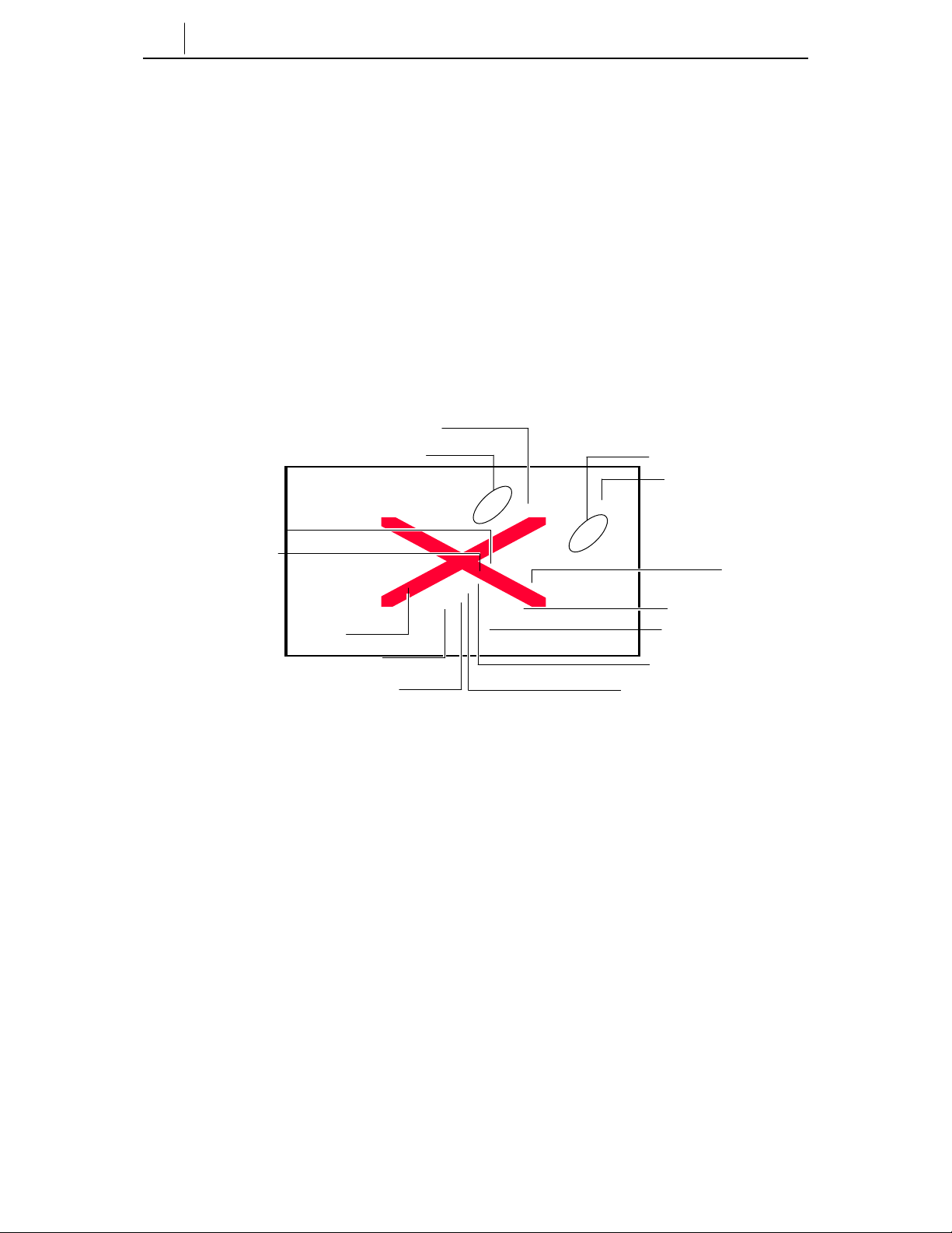
Front Panel of the ITP-5012L
The name and features of each part of ITP-5012L IP phone will be given in detail
below.
Select buttons (6)
Status Indicator
Scroll Button
Navigation Button
Microphone
Conference
Transfer Button
Volume Button
Screen Button
LCD Panel
Select buttons (6)
Dial Button
Speaker Button
Hold Button
Figure 1.1 Front Panel of the ITP-5012L
Dial Button
The dial buttons are used to enter numbers and alpha characters. They are
composed of [0]-[9] digits, as well as the [*] and [#] buttons. Alphabet characters
can also be entered usingthe dial buttons. For convenienceyou can make a call to
one of your phonebook speed dial number by pressing the related dial button for
Page 21

more than 2 seconds.
Select Button
A total of 12 Select buttons are positioned on the left and right side of LCD panel:
6 Select buttons on each side of LCD panel. To select a specific item on the LCD
panel, the users can simply press the Select button next to that item.
Volume Button
The volume button is used to adjust the volume of the handset, speakerphone,
ringer, background music and page announcements. The [u] button lowers the
sound volume and the [t] button increase the sound volume.
Screen Button
The ITP-5012L IP phone has a number of screens of information including, the
Idle screen, Programmable features screen and Fixed features screen. The Screen
button is used to select the required screen.
1-3
Conference Button
This button is used to make a conference call among a group of up to 5 people ,
including the user. If this button is presse d in idle mode, the setup screen for a
conference call will appear on the LCD panel. The conference participants phone
numbers can be entered directly .
Transfer Button
Pressing the Transfer button during a call will cause the setup screen for call
transfer appears on the LCD panel. This button is used in the following cases:
♦ When transferring the current call to another extension user or external party.
♦ To toggle between the caller and another extension user when making an
inquiry call.
Page 22

1-4
Chapter 1 Things You Should Know
Hold Button
The hold button is used to place a call on hold .
Speaker Button
This is used to make a call or speak on the phone without lifting the handset. The
user can answer the phone using the speakerphone by pressing the [Send] button.
To change from the telephone handset to the speakerphone during a call, press the
[Speaker] button and put the replace the handset.
Navigation Buttons
This Navigation buttons help the user easily use various features of the ITP 5012L
phone.
Menu Button
This button displays the main phone menu, which is configured in using icons, for
the various functions available to the user, When using the phones menu system
pressing this button in a menu will display further menu options..
Send Button
The Send button is used to answer and make calls. After dialling the required
party’s phone number with the dial buttons, pressing the Send button makes the
call. Pressing the Send button in the in the ringing state will answer the call, in idle
state it will allow the user to check recently received or called numbers . Also, if
this button is pressed for more than 2 seconds, the last external call can be
redialled.
Enter Button
This button is used to select a highlighted feature or to save information
programmed in the phone’s menu system.
Page 23

1-5
Direction buttons
These buttons are used to navigate through the menu items or to move the cursor
when editing characters (entering or cancelling) on the LCD panel.
♦ [ ] Button
In the idle condition press this button to access the Phone menu. This button
is also used to move the cursor upward in the menu mode or to move to the
previous item from the currently displayed item.
♦ [ ] Button
In the idle condition press this button to access the phones Ring tone and
Volume menu. This button is also used to move the cursor downward in the
menu mode or to move to the next item from the currently displayed item.
♦ [ ] Button
In the idle condition press this button to access the Text Message Menu
. This button is also used to move the cursor to the left in the menu mode.
♦ [ ] Button
In the idle condition press this button to access the phones PhoneBook menu.
This button is used to move the cursor to the right in the menu mode.
End Button
This button is used to disconnect a call after a conversation or return to the last
idle screen when using in the phones menu system.
Cancel Button
This button is used to erase any characters or numbers entered using the dial
buttons, or to move to the previous menu screen when using the phones menu
system.
Page 24

1-6
Chapter 1 Things You Should Know
LCD Panel and Screen Configuration
The LCD panel of ITP-5012L is a graphic LCD supported by 16 gray colors with
a total pixel size of 320 x 240. This can display all alphabet letters and numbers.
On the LCD panel, the call process and progress status will be displayed, as well
as the features available in menu mode.
The LCD of ITP-5012L is configured in two sections: the status section at the top
of the LCD shows using icons alarms, messages, answer mode, network
connection, executive-secretary hot line, etc. and the main section of the screen
displays various program processes and their results.
Status Icons
♦ : Executive-Secretary
♦ : Forward
♦ : Call Back
♦ : Answer Mode
♦ : Do Not Disturb (DND)
♦
: Headset
♦ : Group Listen
♦ : Mute
♦ : Alarm
♦ : Message
♦ : Network Connection
Page 25

Figure 1.2 Status Screen of the LCD Panel
Scroll Key
Can be used as an alternative to the Navigation button to to quickly move between
the items displayed in the phone menu system..
Microphone
At the right of the speaker button, there is a microphone that looks like a small
hole. This allows users to can speak to there callers in speakerphone mode . To do
so, press the speaker button first.
Status Indicator
The status indicator is positioned in the upper right hand corner of the LCD panel.
The indicator shows the IP phone status in 3 colors, red, pink and blue.
Ta ble 1.1 S tatus Indicator
1-7
Features Status of LCD Indicators
Busy/Off-Hook Steady red.
Station Ring Flashing red slowly.
Trunk. Ring Flashing blue slowly.
Recall Ring Flashing blue rapidly.
Message Camp On Flashing red.
Do Not Disturb Fast flashing red with in 1 -sec ond inte r val.
Transfer/Hold/Speaker Button LED
The [Transfer] button, [Hold] button, and [Speaker] button have a LED indicator
that displays a red LED whenever any of those buttons is pressed or according to
the phone status. Refer below .
Page 26
1-8
Chapter 1 Things You Should Know
Rear Panel of ITP-5012L
On the rear panel of ITP-5012L phone, there are the power connection jack, PC
connection jack and LAN connection jack.
LAN Connection Jack
PC Connection Jack
Power Connection Jack
Figure 1.3 Rear Panel of the ITP-5012L
The ITP-5012L IP phone is supplied with a A C power adapter and this
adaptor must be used.
If an alternative power adapter is used for, the ITP-5012L IP phone this may
result in serious damage a nd vo ids the w arra nty.
Page 27
Bottom Panel of ITP-5012L
On the bottom of ITP-5012L IP phone, there are the handset cord jack and line-out
jack for connection to a recording device.
Recording device connection jack
Handset connection jack
Figure 1.4 Bottom Panel of the ITP-5012L
1-9
To the recording device line-out jack, any general recording device can be
connected. The users can connect a tape recorder to record any te lep hone
conversation.
Page 28

1-10
Chapter 1 Things You Should Know
(This page intentionally left blank.)
Page 29

1-11
Page 30

Page 31

Chapter2 Assembling ITP-5012L
This chapter explains how to install the ITP-5012L IP phone.
Before you use the ITP-5012L
Before using the ITP-5012L IP phone, the user must check each component inside
the package first and then put them together carefully.
Checking the parts in the ITP-5012L package
After purchasing the ITP-5012L IP phone, the user must check if the package box
includes the following items:
♦
2-1
Handset
LAN cable
If any of the parts explained above is missin g , p lease contact your Authorised
ITP-5012L
Power adapter
Figure 2.1 Components of the ITP-5012L Package
Samsung reseller.
Phone support
User guide
Page 32

2-2
Chapter2 Assembling ITP-5012L IP Phone
Installing the ITP-5012L
Install the ITP-5012L IP phone in the following order:
1. First, connect the handset to the handset connection jack at the bottom of the
IP phone.
Figure 2. 2 C on n e c t in g t he Handset to the ITP-5012L
Page 33

2-3
2. To add the phone support to the ITP-5012L IP phone, insert the support into the
left/right holes that are located in the upper section of the bottom panel.
Figure 2.3 Adding the Desk Support int o the ITP-5012L
3. Connect one end of the LAN cable (Disconnect it from PC first while the other
end is still connected to the data network socket) to the LAN connection jack
at the rear of the ITP-5012L IP phone.
Data Network
Figure 2 .4 C on n e c t i n g t he LAN cabl e to the ITP-5012L
Page 34

2-4
Chapter2 Assembling ITP-5012L IP Phone
4. Connect the new LAN cable provided with the phone to the PC network card
and connect the other end to the PC connection jack at the rear of the ITP5012L IP phone.
Figure 2.5 Connecti n g PC to the ITP-5012L
Be careful not to connect the network LAN cable to the PC connector of
the ITP 5012L phone.
If the LAN network cable is connected to the PC connection port of the phone ,
both telephone and PC communication s will be lost.
Page 35

5. Connect the power adapter. At the rear of ITP-5012L IP phone, there is the
power connection jack for connection to the power adapter. Connect the
power adapter to that power connection jack and connect the plug into the
wall socket.The ITP-5012L IP phone will automatically starts booting.
2-5
Figure 2. 6 C on necting Po wer adapter to the ITP-5012L
The ITP-5012L IP phone is supplied with a A C power adapter and this
adaptor must be used.
If an alternative power adapter is used for, the ITP-5012L IP phone this may
result in serious damage a nd vo ids the w arra nty.
Page 36

2-6
Chapter2 Assembling ITP-5012L IP Phone
6. To connect any recording device to the ITP-5012L IP phone, the user must
connect it to the REC connection jack at the bottom of the IP phone.
Figure 2.7 Connecting the Recording Device to the Phone
Page 37

Chapter 3 Getting Started
This chapter explains how to set up the user environment for the ITP-5012L IP
phone.
Booting the ITP-5012L
To set the environment parameters, press and hold the Menu button while you turn
on the pwer to the ITP5012L phone. As soon as the ITP-5012L IP phone is
connected to the power supply, the phone boots up and the LCD panel shows the
following messgage:
Setup (1/6)
1.Infomation
2.Network
3.Load & Upgrade
4 System
54.Server
6.Exit
3-1
On the screen, the ‘Setup (1/6)’ part will be displayed and the currently selected
item will be reversed into a lighter co lo r. This applies to the entire menu as shown
in the figure above.
Page 38

3-2
Chapter3 Getting Started
Environment Setting Mode
When the ITP-5012L IP phone is installed for the first time or the system settings
are changed, the phone settings must be modified to match your data network
environmentt. If there is no current settings when booting the phone or if the
system is not correctly connected, the phone enters in the environment setting
mode so that the users can check and modify the setting status.
To enter the environmen t setting mode, press the [menu] button from the
navigation buttons as soon as the ITP-5012L IP phone is connected to the power
supply .
In the environment setting mode, the LCD panel shows the following messages:
Setup (1/6)
1.Infomation
2.Network
3.Load & Upgrade
4.System
5.Server
6.Exit
At this time, the user can move to each menu item by using the navigation buttons
or [1]~[9] dial buttons of the ITP-5012L IP phone.
♦ Up/down navigation buttons: Used when moving upward/downward between
menu items .
♦ Left/right navigation buttons: If there is a sub menu, move to the sub menu
and if a menu is at the last line, that menu will be executed.
♦ [0]~[9] dial buttons: Can be used to select a menu by number
♦ [Enter] button: Used toenter a sub menu or to save and close the modifications
to the selected sub menu.
Page 39

♦ [Menu] button: Used to enter the initial Setup menu on powering up the
phone.
♦ [End] Button: Used to return to the previous menu from the current menu or
when cancelling the modifications made.
Menu Structure
The environment setting menu is configured as the following structure:
3-3
Page 40

3-4
Chapter3 Getting Started
1. Information
--- 1.Version
2.Network
3.Load Option
4.MAC address
(* No.3 will be indicated only when Manual IP is selected in the
Network/Mode menu)
2. Network
--- 1. Mode
2. IP
3. Netmask
4. Gateway
(* No.2~5 will be indicated only when Manual IP Mode is selected in the Network/Mod e
menu)
3.Load & Upgrade
--- 1. Load Option
2. Upgrade Program
3. Upgrade Bootrom
4. Format
4. System
1. Password
5. Server
--- 1. Server IP
2. ID
3. Password
6.Exit
Page 41
Using the Buttons in Edit Mode
In Edit mode for each menu, the LCD panel shows a cursor.The user can edit the
setting by using [0]~[9] dial buttons and [*] dial button.
The buttons used for editing and their features are summarized in the following
table.
Ta ble 3.1 Nav igation Buttons Used for Editing
Button Features
Left/Right buttons To move a cursor or to erase what is entered.
[Enter] button To save the current setting and end setting.
[End] button To cancel the current setting and end setting.
[*] dial button To enter (.)
[0] ~ [9] dial buttons To enter numbers
3-5
Refer to ‘Chapter 1’ for the lo ca tion of each button on the phone.
Page 42

3-6
Chapter3 Getting Started
Setting Environment
Select each menu for environment setting, set the user-friendly environment for
the ITP-5012L IP phone.
Tel. Number Set/Modify
The phone numbers shall not be set up separately on the phone. Enter ID and
password of the server below to register the phone.
Network Set/Modify
From the Setup menu, ‘2.Network’ is used to set or modify the network
environment. After selecting the ‘2.Network’ menu from the LCD panel to the
following sub menu and options will be displayed:
Network (1/4)
1.Mode
2. IP
3. Netmask
4. Gateway
After selecting ‘1.Mode’ and moving to its sub menu, the LCD panel will show
the following options:
Mode (1/3)
1. Manual IP
2. DHCP
3. PPPoE
♦ If ‘1.Manual IP’ is selected, the user can directly enter the IP address, subnet
mask, and gateway value.
♦ If ‘2.DHCP’ is selected, the IP address, subnet mask, and gateway value will
be set to the default values automatically.
♦
Page 43

3-7
♦ If 3 PPPoE is selected ??????????????
Setting IP Manually
If ‘1.Manual IP’ is selected in Mode, sub menu 2 to 4 will be displayed on the
LCD panel.
Network (2/4)
1.Mode
2.IP
3.Netmask
4.Gateway
The user may directly enter the IP address, subnet mask, and gateway, address as
follows:
♦ If the ‘2.IP’ menu is selected, the LCD panel will show the following message
and the user can enter the ITP phone’s IP address.
* Input IP Address
xxx.xxx.xxx.xxx
Check if there is any currently saved IP address of the phone on the LCD panel. If
the IP address has not been set, the LCD panel shows nothing. The user can enter
the IP address by using the dial buttons and [*] button to enter ‘.’. After the
correct IP address has been entered press the [Enter] button to save the setting.
♦ If the ‘3.Netmask’ menu is selected, the LCD panel will show the following
message and the user can enter a new Netmask IP address.
* Input Netmask
xxx.xxx.xxx.xxx
Check if there is any currently saved subnet mask address of the phone on the
LCD panel. If the subnet mask address has not been set, the LCD panel will show
nothing. Enter the Netmask using the dial buttons and [*] button to enter ‘.’. After
Page 44

3-8
Chapter3 Getting Started
the correct subnet mask has been entered press the [Enter] button to save the
setting.
♦ If the ‘4.Gateway’ menu is selected, the LCD panel will show the following
message and the user can enter a new gateway address.
* Input Def. Gateway
xxx.xxx.xxx.xxx
The user can check if there is any gateway IP address currently saved on the LCD
panel. If the gateway IP address has not been set, the LCD panel will show
nothing. Use the dial buttons to enter the Gateway IP Address and the [*] button to
enter ‘.’. After the correct gateway IP address has been entered press the [Enter]
button to save the setting.
, If ‘2.DHCP’ is selected from the ‘1.Mode’ menu the ‘IP’, ’Netmask’, and ‘Gateway’
options, will not be displayed on the LCD panel.
Page 45

3-9
Load & Upgrade Set/Modify
In the Network menu, ‘3.Load & Upgrade’ menu is used to set or modify the
environment mode and upgrading of the ITP phones software. The user must
confirm the appropriate settings from their system Administrator prior tousing this
menu.
After selecting ‘3.Load & Upgrade’ me nu on the LCD panel the following sub
menu will be displayed:
Load & Upgrade (1/4)
1.Load Option
2.Upgrade Program
3.Upgrade Bootrom
4.Format
♦ Selecting ‘1.Load Option’ menu and its sub menu will be displayed. Ththe
user can select ‘1.File System’. to load the software program saved in the flash
memory or 2. TFTP down run to program the IP address of the TFTP server to
be used to upgrade the ITP phone software. Consult your system administrator
before trying to Upgrade your ITP phone software.
The file system here means the flash file system existing in the flash memory of
the ITP phone. If ‘2.tftp server’ is selected from the sub menus, the program saved
in the flash memory doesn’t operate. In stead, the progra m existin g in the TFTP
server will be downloaded to the RAM of the ITP Phone. Therefore, the user must
use the TFTP server and set its IP address to upgrade the current software on the
ITP phone.
Use the dial buttons to enter the TFTP server IP Address and the [*] button to enter ‘.’. After the
correct TFTP Server IP address has been ente red press the [En ter] button to save
the setting.
♦ The ‘2.Upgrade Program’ menu is used to upgrade the ITP software programs.
Set the IP address of TFTP server that the user wants to upgrade and then press
the [Enter] button
♦ The ‘3.Upgrade Bootrom’ menu is used to upgrade the ITP Phone’s Bootrom.
Page 46

3-10
Chapter3 Getting Started
Set the IP address of TFTP server that the user wants to upgrade and then press
the [Enter] button.
♦ The ‘4.Format’ menu is used to dele te the current program values or its
relevant flash information.
Authentication Server Related Set/Modify
From the Setup menu, ‘5.Server’ menu is used to set or modify the associated
values of the authentication server which in this case is the IP address of the
OfficeServ system. After selecting ‘5.Server’ to the following sub menu will be
displayed.
Server (1/3)
1.Server IP
2.ID
3.Password
♦ The ‘1.Server IP’ menu is used to set or modify the IP address of the
authentication server. If moved to its sub menu, the LCD panel will show the
following message:
* Input ServerIP
xxx.xxx.xxx.xxx
Check if there is any currently saved IP address for the authentication server on
the LCD panel. If IP address has not been set, the LCD panel will show nothing.
The user can enter the server IP address by using the dial buttons and [*] button to
enter ‘.’.To save the setting by pressing the [Enter] button.
♦ ‘2. ID’ and ‘3. Password’ are the user information to access to the server.
* ID
SAMSUNG
Page 47

* Input Password
*********
The ID can be a maximum of 16 letters. Both letters and numbers can be used.
The Password can be a maximum of 8 numbers only. When entering numbers,
they appear as asterisks (*) on the screen.
The user shall set the correct ID and password to use the phone and it is
recommended that you ask your system administrator of OfficeServ system for an
appropriate ID and password before setting this option.
Completion of Settings
After completing setup for your environment, select ‘1.Information’ from the main
setup menu to check the setting status. Select the ‘6.Exit’ and then the new setting
values will be saved. The ITP-5012L IP phone will start rebooting automatically
on exit.
3-11
Page 48

Page 49

Chapter 4 Basic Features
This chapter describes the various calling features.
Please take the time to understand the use of vario us bu ttons o f th e ITP-5012L IP
phone before using the phone. Refer to ‘Chapter 1’ of this manual, which
describes the various buttons of the ITP-5012L IP phone.
Dialling from Recent Call Log
1. Press the [Send] button briefly when the phone is idleand you can view
outgoing calls you have made in the Recent Call Log, Pressed and hold this
button for about 2 seconds, to redial the last number dialled.
2. Up to 60 numbers that were recently sent or received are displayed in the order
dialled.
4-1
Figure 4.1 Recent Call Log
3. Place the cursor on the desired item by pressing the Select button or the
direction button.
4..
Page 50

4-2
Chapter4 Basic Features
Press the [Send] button to connect to the number of the selected item, or
alternatively,
Press the [Enter] button to view the detailed information associated with the
call selected including the parties name, if available, time of the call, and call
duration time. After viewing the inf orma tion, press the [Send] button to dial
the number of the selected item.
5. This will automatically make the call through the speakerphone. You can switch
from the speakerphone to the handset by lifting the handset.
Dialling from the Outgoing/Incoming Menu
Up to 30 incoming or outgoing numbers can be viewed and dialled using the
Outgoing or incoming number menus in your ITP 50012L phonebook.
1. Press the [Menu] button with the idle screen of the phone displayed, and select
the PhoneBook icon.
Figure 4.2 PhoneBook
2. Select the Outgoing or Incoming menu of PhoneBook.
3. Up to 30 numbers listed in the selected menu are displayed.
4. Place the cursor on the desired number by pressing the Select button or the
direction buttons.
5. Press the [Send] button to connect to the number of the selected item, or
Page 51

alternatively,
Press the [Enter] button to view the detailed information associated with the
call selected including the parties name, if available, time of the call, and call
duration time. After viewing the inf orma tion, press the [Send] button to dial
the number of the selected item.
.
6. This will automatically make the call through the speakerphone. You can switch
from the speakerphone to the handset by lifting the handset.
Speed Dialling
The telephone numbers stored in the ITP-5012L IP phone are assigned to each
speed dial number. The user can personally assign the speed dial number,
otherwise the speed dial number will be assigned automatically.
1. Press and hold the speed dial number of the desired telephone number with the
initial screen of the phone displayed.
2. When the speed dial number consists of more than two digits, briefly press the
digit or digits other than the last digit, and press and hold the last digit.
3. The user can make a call through the speakerphone. User can switch from the
speakerphone to the handset by lifting the handset.
4-3
Calling through Speakerphone
1. Press the [Speaker] button with the idle screen of the phone displayed.
2. The phone number entry screen is displayed. Press the [uVolumet] button to
adjust the speaker volume.
3. Enter the desired number, and press the [Send] button to connect the call
through the speakerphone. The user can switch from the speakerphone to the
Page 52

4-4
Chapter4 Basic Features
handset by lifting the handset.
To make a call from the Recent Call Log, press the [Send] button, and follow the
procedure of “ Dialling from Recent Call Log”. You can make a call by pressing the
speed dial number with th e phone number entry screen displayed.
Calling through Handset
1. Lift the handset with the idle screen of the phone displayed.
2. W ith the phone number entry screen displayed, press the [uVolumet] button
to adjust the speaker volume.
3. Enter the desired number, and press the [Send] button. Upon connection, speak
through the handset. Press the [Speaker] button and replace the handset to
switch to the speakerphone.
To make a call from Recent Call Log, press the [Send] button, and follow the
procedure of “Dialling from Recent Call Log”.
Page 53

Answering Calls
1. When a call arrives, a call receipt message will be displayed on the LCD panel
as shown in the figure below .
2. Press the [uVolumet] button to adjust the volume of the ringer.
3. Press the [Send] button to answer the call using the speakerphone. While
talking using the speakerphone, you can switch from the speakerphone to the
handset by lifting the handset.
4-5
Figure 4.3 Call Receipt Message
Page 54

4-6
Chapter4 Basic Features
Conference Calls
The Conference feature supports up to 5 parties (Intercom & external trunk.lines),
including yourself To setup a conference press the [Conference] button and the
Conference screen will be displayed as shown below.
♦ Enter the phone numbers of the parties you wish to conference with followed
by [Enter]. Use the navigation UP/DOWN keys to move the cursor between
the entry boxes and options, or
♦ Press the [Group] button and select the group from the address book, or
directly enter the group number.
Figure 4.4 Conference Group
Page 55

Conference Groups
With the [Conference] screen displayed, press the [Group] button to display the
Group screen as shown below .
Figure 4.5 Conference Group
To add a Conference Group
♦ In the [Conference] screen enter the required conference members pressing
after eeach member has been added
♦ Press the [Group] key and place the cursor on a free group block and press the
[Menu] key.
♦ Select the save option with the cursor and press [Enter] or dial 2.
♦ Enter the Group name and press the [Enter] to save the group name.
To delete a Conference Group
♦ Place the cursor on the desired group and press the [Menu] key.
♦ Place the cursor on the Delete option and press the [Enter] button to delete a
groupor dial 3 to delete the group.
4-7
Page 56

4-8
Chapter4 Basic Features
Connecting Conference.
After selecting or directly entering the conference group, press the [Send All]
button to attempt ‘conference connection’.
To save the conference members as a Conference group
♦ With the [Conference Connection Status] screen displayed, press the [Group]
button.
♦ Select a free Conference group and press [Menu] followed by [Save].
♦ Enter the Conference Group name and then press [Enter] to save.
♦ To return to the Connection Status screen press [Cancel].
Note: This diagram needs to
Changed to correctly show
Status, currently shows
Connected member
Group members not connected
Figure 4.6 Conference Connection Status
♦ Connections to the numbers who were not connected can be reattempted by
pressing the [Sending] button.
♦ Press the [Delete] button to drop a connected participant during the conference
call. This member can be added to the conference again by pressing the
[Sending] key.
Page 57

Screen Features
The ITP-5012L IP phone offers a number of additional convenience features with
the OfficeServ system.
Press the [Screen] button with the idle screen of the phone displayed. The basic
screen (calendar image), Programmable Feature key screen, Fixed Feature Menu
screen, and the Executive status display screen are displayed consecutively.
Figure 4.7 Basic Screen when using the Screen Button
4-9
Figure 4.8 Programmable Feature screen
Page 58

4-10
Chapter4 Basic Features
Figure 4.9 Fixed Feature screen.
Figure 4.10 Executive Status Display Screen
Dialling Directly from the Programmable Feature Key screen
You can use the features programmed by your System Administrator or Easysetby
simply pressing the [Select] key. The feat ures available include, speed dial keys,
Direct Station Select (DSS)keys for other extension users as well as other
OfficeServ system features
♦ Press the [Screen] button until the Programmable Feature Key screen is
displayed.
♦
♦ Use the scroll key or the screen UP/DOWN keys to locate the party you wish
Page 59

4-11
to call
♦ You can connect to the selected number by pressing the [Select] button beside
the intercom or speed dial name or number.
Page 60

4-12
Chapter4 Basic Features
Fixed Feature Key Menu
Press the [Screen] button until the Fixed Feature Menu is displayed on the screen.
With the Fixed Feature Menu screen displayed, you can use the convenient
features shown below by pressing the associated [Select] button.
♦ LAST REDIAL
♦ SPEED DIAL
♦ SAVE/REPEAT
♦
♦ DIRECTORY
♦ PAGE
♦
♦ PAGE PICKUP
♦ MEET ME PAGE
♦ DIR. PICKUP
♦ VM MESSAGE
♦ STN MESSAGE
♦ HOLD PICKUP
♦
♦
♦ UNIV. ANSWER
♦ DND
♦ STATUS MSG
♦ IN/OUT GROUP
♦ OHVA BLOCK
♦ TIMER???????
‘Chapter 5’ of this manual details the procedures for each feature.
Page 61

Executive/Secretary
The user can set the status display feature and the message feature in the phone
where the Executive/secretary feature has been set. The user can use
Executive/Secretary features only in the phone where the Executive/secretary
feature is programmed. Refer to your System Administrator if you are unsure
whether you have access to this feature.
Executive Status Display
The secretary can conveniently set the status of the executive.
1. Press the [Screen] button until the Executive status is displayed on the screen.
4-13
Figure 4.11 Executive Status Display
2. Set the executive status appropriate to each situation by pressing [Select]
button of the corresponding Executive.
Page 62

4-14
Chapter4 Basic Features
Executive/Secretary Message
Messages that are frequently used can be set and used conveniently.
1. Press the [EXE/SECR MSG] button among the Select buttons of the Soft
Screen.
2. This brings up a screen asking the user to select where to send the message.
This screen is not displayed when there is only one executive or secretary.
Select the check box of the desired recipient by pressing the Select button on
the left side of the screen. Up to four recipients can be selected. Press the
[Enter] button.
Figure 4.12 Selecting Executive/Secreta ry Me ssage Rec ipie nt
Page 63

3. After selecting the recipient, the sc reen will ask the user to select which
message to send. Press the [Enter] button after selecting the message by using
the direction buttons.
Figure 4.13 Selecting Executive/Secreta ry Messa ge
4. There are no defined messages when the Executive/Secretary feature is first
used. Press the [Menu] button to enter the message. The user can enter a new
message by pressing the [Menu] button.
♦ When the user presses the [Menu] button after placing the cursor on the
desired item, a small window pops up. Select [Edit] and press the [Enter]
button. The [Input Message] screen is displayed as shown below. Enter a
message with less than 8 characters.
4-15
Figure 4.14 Entering Executive/Secretary Message
Page 64

4-16
Chapter4 Basic Features
When the user wants to delete the entered message, select the message and
press the [Menu] button. The Delete/ Cancel menu pops up. Delete the
message by selecting [Delete].
Page 65

Message
The user can leave messages or cancel/confirm/return messages by using AOM
screen Menu or feature codes.
Leaving Messages
The user can leave a message on another extension when there is no answer or if
the line is busy.
1. Press the [Screen] button until the AOM screen is displayed.
2. Press the Select button of the [Display Message] menu of the AOM screen.
3. Hang up after the confirmation tone.
Leaving massages only applies to intercom calls.
4-17
Message Cancel
The user can cancel the message (or the number) left on another station or those
left on the user’s phone.
Cancelling Messages left on Other Stations
1. Press the dial button [4][2], and the [Send] button.
2. Press the extension number where the phone number (or the message) was left.
Cancelling All Received Messages.
1. Press the dial button [4][2] and the [Send] button.
2. Press the extension number of the user’s phone.
Page 66

4-18
Chapter4 Basic Features
Confirming/ Returning/ Deleting Messages
If a massage is left on the user’ s phone, the phone status indicator flashes a red
light.
1. Press the [Screen] button until the AOM screen is displayed.
2. Press the Select button of the [Display Message] Menu displayed on the AOM
screen
3. The extension number of the first message is displayed on the screen, and the
[Message response], [Next message], and [Delete] menus are displayed.
♦
♦ To return the message, press the Select button of the [Return Message] menu.
Then the extension number of the message is connected automatically . If the
extension number does not answer, the red light continues to flash on the
status indicator.
♦ If there are multiple messages left, press the Select button of the [Next
Message] menu, and return or delete the message.
♦ To delete the message, press the Select button of the [Delete] menu.
Page 67

4-19
(This page intentionally left blank.)
Page 68

Page 69

Chapter 5 Fixed Feature Menus
This chapter describes how to use the convenient features from the Fixed Feature
Menu screen of the ITP-5012L IP phone.
Please take the time to understand the use of the fixed features buttons of the
ITP-5012L IP phone before using the phone . R efer to ‘Chapter 1’ of this manual,
which describes the various buttons of the ITP-5012L IP phone.
Entering the Fixed Feature Menu screen
Press the [Screen] button until the Fixed Feature Menu screen is displayed as
shown below
5-1
Press the Select
button to move to
the next page.
Press the Select
button to move to
the previous page.
Figure 5.1 Soft Menu screen
Page 70

5-2
Chapter5 Soft Menus
Menu Selection
♦ Press the [Select] button of each menu displayed on the screen to use the
corresponding feature.
♦ Use the scroll key on the phone to view rest of the menus that are not visible in
the first screen.
♦ Use the scroll key or the navigation buttons on the phone to move to and select
a menu.
Fixed Feature Menu
The following features are available on the Fixed Feature Menu screen.
♦ LAST REDIAL
♦ SPEED DIAL
♦ SAVE/REPEAT
♦ DIRECTORY
♦ PAGE
♦ PAGE PICKUP
♦ MEET ME PAGE
♦ DIR. PICKUP
♦ VM MESSAGE
♦ STN MESSAGE
♦ HOLD PICKUP
♦ UNIV. ANSWER
♦ DND
♦ STATUS MSG
♦ IN/OUT GROUP
♦ OHVA BLOCK
♦ TIMER???????
Page 71

Last Redial
The user can redial the most recently dialled external number.
1. Press the Select button for [LAST REDIAL
2. Make the call.
The redial feature does not apply to inte rcom ca lls.
Automatic Redial/Retry
If the called external number is is busy, the phone redials the called number
automatically . It can redial up to 99 times depending on the OfficeServ system
programming.
1. Upon hearing the busy tone, press the Select button for Automatic Redial/Retry.
2. The system will redial the same number automatically. The user can hear the
dial tone through the speaker and the microphone is disabled.
3. When the other party answers, you can lift the handset or press the [Speaker]
button or the [Send] button before the other party speaks. Y ou must respond
within 10 seconds.
5-3
- If you dial another number, automatic redial is cancelled.
- To cancel automatic redial, lift and replace the handset.
Save/Repeat
Page 72

5-4
Chapter5 Soft Menus
You can save the last dialled external number and redial the number later.
1. Press the Select button for SAVE/REPEAT before hanging up your call to save
the phone number.
2. You can redial the saved number anytime by pressing the Select button for
SAVE/REPEAT
- The saved number is stored in the memory until you save another number.
- The saved number redial feature does not apply to intercom calls.
Page 73

Speed Dial
The Samsung OfficeServ system provides both a system wide speed dial list and a
personal speed dial list for each phone user. You can select an external number
programmed into either list tomake a call by entering the speed dial number.
1. Press the [Select] button for SPEED DIAL and you will be prompted for the
speed dial number
2. Enter the registered speed dial number.
3. The phone number assigned to the speed dial number is dialled automatically
using the speakerphone.
Consult your System Ad ministra to r for the list of y our system’s speed dial
5-5
number .
Page 74

5-6
Chapter5 Soft Menus
Directory
Each extension number, System and personal speed dial number can have a
corresponding directory name. You can call anextension number or the desired
speed dial number by by name in the directory list, which is in an alphabetical
order.
1. Press the [Select] button for DIRECTORY and you will be prompted to select
the list requiredplayed on the Soft Menu screen.
2. Press the [Select] button for the desired directory
([PERSONAL]/[SYSTEM]/[STA TION])
3. Enter the first letter of the desired name by using the dial button.
4. Search the desired name by using the [uVolumet] button
5. Press the [Select] button for the desired name.
6. The corresponding number is dialled automatically using the speakerphone.
Page
The OfficeServ system allows you to make page announcements to groups of
internal extensions or via external speakers. You can page specific extensions
through the phone speaker or externally through external speakers using the PAGE
key.
To move directly to a specified directory list, you can add an programmed button
in the Programmable Features Menu for each of th e lists.
When making a page announcemen t, you must use the hand se t for best audio
Page 75

quality.
Internal Page
The user can page through the phone speaker.
1. Lift the handset, and check for the phone number entry screen.
2. Press the [Select] button for Page
3. Dial the desired zone number [1], [2], [3], or [4], or press [0] to page all
internal zones.
4. Af ter the confirmation t one, make the announcement.
5. After the announcement, replace the handset down.
5-7
External Page
The user can page externally through the external speaker.
1. Lift the handset, and check for the phone number entry screen.
2. Press the [Select] button for PAGE
3. Dial the desired zone number [4],[5],[6],[7],or [8], or press [9] to page all
external zones.
4. Af ter the confirmation t one, make the announcement.
5. After the announcement, replace the handset down.
All Page
The user can also page both internally and externally simultaneously.
Page 76

5-8
Chapter5 Soft Menus
1. Lift the handset.
2. Press the [Select] button for PAGE
3. Dial the [*] button.
4. After the confirmation tone, make the page announcement.
5. After the announcement, replace the handset down.
Page 77

Call Park And Page
While on external call you canautomatically park a call when you make a page
annoncement to locate the person required by the caller.
1. While on a external call press the [Select] button for PAGE] displayed on the
Soft Menu.
2. The call will be parked automatically.
3. Dial the desired page zone number and announce the trunk. line number where
the call is parked.
4. Replace the phone.
If the parked call is not answered within the preset time, it will recall you. This Call
Park and Page feature does not apply to interco m calls.
5-9
Page 78

5-10
Chapter5 Soft Menus
Page Pickup
Allows you to connect to the extension or trunk. line number advised in a page
announcement
1. Lift the handset.
2. Press the [Select] button for PAGE PICKUP
3. Enter the extension number or the trunk. line number advised by the page
announcement.
Dir. PickupThe Direct Pickup button allows you to pick up a ringing call at
another extension.
1. Press the [Select] button for DIR. PICKUP.
2. Dial the ringing extension number.
3. You can now talk to the caller on the speakerphone or lift the handset
SVMi Message
When your OfficeServ system has a Samsung voice mail card installed, you can
directly access your Voice Mailbox quickly and conveniently.. The message icon
will be displayed and the status indicator will flash to indicate you have received a
message
1. Press the [Select] button for VM MESSAGE in the Fixed Feature screen.
2. Follow the prompts of the SVMi Voicemail card.
STN Message
The OfficeServ system allows our extension users to leave a station message for
Page 79

you if they require your assistance. The message icon will be displayed and the
status indicator will flash to indicate you have received a message. You can review
and respond to the station message list using the Station Message button
1. Press the [Select] button for STN MESSAGE.
2. The first message left for your phone will be displayed, press the [Select]
button for NEXT to review other messages left for you.
3. Press the [Select] button for REPLY to ring the extension that left the message
or press the [Select] button for CLEAR to clear the message left.
Hold Pickup
You can pickup a call placed on system hold by another extension using the Hold
Pickup feature. You can pickup internal calls placed on hold or trunks placed in
exclusive hold.
1. To retrieve the held call, press the [Select] button for HOLD PICKUP.
2. Dial the extension number that placed the call on system hold or the trunk
number.
3. You can now talk to the caller on the speakerphone or lift the handset.
5-11
Page 80

5-12
Chapter5 Soft Menus
Page 81

5-13
Page 82

5-14
Chapter5 Soft Menus
Do Not Disturb
When DND is registered, incoming calls are forwarded to the DND forward
destination if programmed or the caller will receive busy tone..
Setting DND
This feature is used to block incoming calls. Calls can still be made in the DND
mode.
1. W ith the handset in place, press the [Select] button for DND and the DND
Menu will be displayed.
2. Press the [Select] button for [ON.
3. Confirmation tone will be heard and the phone status indicator will flash
indicating that DND is set.
Cancelling DND
1. Check if the status indicator is flashing and the DND icon is set.
2. Press the [Select] button for DND and the DND Menu will be displayed.
3. Press the [Select] button for OFF.
4. Confirmation tone will be heard and DND is Cancelled will be displayed. The
status indicator cease to flash a few seconds after [DND] mode is cancelled.
Page 83

Universal Answer
If a call arrives when the system is in Night mode, external speakers can be used
to ring the night bell. To answer the call press the [Select] button for [UNIV,
ANSWER
5-15
Page 84

5-16
Chapter5 Soft Menus
Status Message
You can leave a status message for your internal callers should you be absent from
your desk for a while. The caller can see the message displayed on their phone
LCD when they call your extension.
1. Press the [Select] button for STATUS MSG.
2. Press the desired status message code. (Refer to ‘Annex’ of this manual for the
status messages of each code or your System Administrator).
3. To cancel the status message, press the [Select] button for STATUS MSG and
dial the cancel code [0][0].
Page 85

In/Out Group
If your phone is assigned to an station ring group, you can assign or remove your
phone to or from the group. When the phone is removed from the group, you
cannot answer incoming calls to the station group number.
1. Press the [Select] button for IN/OUT GROUP.
2. Enter the number of the station group, you intend to assign or remove your
phone number. The [In Group] or [Out of Group] options are displayed on
screen.
3. To assign your telephone number to the group, press the [Select] button for [In
Group].
4. To remove your telephone number from the group, press the [Select] button for
Out of Group
5. Repeat the above procedure (1~ 4) when necessary.
5-17
OHVA BLOCK
You can set or cancel OHVA Block which prevents or allows other users from
making an Off Hook Voice Announcement to you when you are on a internal or
external call.
1. Press the [Select] button for OHVA BLOCK.
2. Press the [Select] button of the ON to set OHVA BLOCK
3. Press the [Select] button for OFF to cancel the OHVA BLOCK.
4. The display will advise the OHVA Block status after the [Select] button is
pressed.
Off-Hook Voice Announce feature is used by a third party to make an
Page 86

5-18
Chapter5 Soft Menus
Timer
Call Duration Timer
You can set the Call Duration Timer to operate automatically for external calls.
Upon dialling the number, the timer is displayed immediately for incoming Trunk.
calls, after a moment or when the recipient answers for outgoing calls.
The timer operates during the call. The duration time is displayed in minutes and
seconds.The timer restarts after 100 minutes
Timer Function
The timer can be used as a simple stopwatch.
1. When the phone is in a waiting status, press the [Select] button for TIMER to
2. Select the [TIMER] menu again to stop measuring time.
3. Check the elapsed time displayed on the screen.
4. Lift and replace the handset to return to the idle screen.
announcement only toa user who is busy on call.
start measuring time.
Page 87

5-19
(This page intentionally left blank.)
Page 88

Page 89

Chapter 6 Application Program Menus
This chapter describes how to use the enhanced Menu applications of the ITP5012L IP phone.
You will need to understand the fun ction s of each button on the ITP-5012L IP
phone to make use of the menu applications The description of each button and
its function is defined in ‘ Chapter 1’ of this manual.
About Main Menu
Press the [Menu] button from the ITP-5012L IP phone. Then, the main menu with
application icons will appear as shown below:
6-1
Figure 6.1 Main Menu Screen of Applications
Page 90

6-2
Chapter6 Application Program Menus
Navigating your way through the Menus
Use the navigation buttons to select the required menu. To select a menu item you
can use the navigation buttons or the dial buttons
To select a menu icon
Use the direction buttons to select an icon. Then, press the [Enter] button.
To select amenu item from the list
Method 1. Use the direction buttons to select an item. Then, press the [Enter]
button.
Method 2. In the list, each item has a number in the left. Dial the number that
corresponds to the number of the desired item.
Page 91

Using the PhoneBook
1. Press the [Menu] button from the phone to see the main menu.
2. Use the direction buttons to select the [P-Book] icon. Then, press the [Enter]
button.
6-3
Figure 6.2 Selecting the [Phone Book] Menu
3. The [PhoneBook] screen appears as shown below: You may now select the
desired menu item. Refer below..
Figure 6.3 PhoneBook
Page 92

6-4
Chapter6 Application Program Menus
Searching for a Telephone Number
Allows you to search for any telephone numbers you have programmed into the
phone easily . You can search by speed dial location number/name/telephone
number/group/time.
1. Dial [1] from the [PhoneBook] screen to select the [1.Search].
Figure 6.4 Selecting the [Search] Menu
2. The [Search] screen appears as shown below:
Figure 6.5 Sub-Menus of the [Search] Menu
Page 93

Search by Speed Dial Number Location
You can search for the desired telephone number based on the speed dial number
location registered with the phone. Each speed dial number location will have an
associated speed dial name and up to 5 telephone numbers can be programmed for
each speed dial name.
1. Press the dial button [1] from the [Search] screen to select the [1.By speed dial
#].
6-5
Figure 6.6 Selecting the [By speed dial #] Menu
2. Enter a speed dial number location on the screen that prompts you to enter a
speed dial number and press the [Enter] button. The associated speed dial
name will be displayed from the [PhoneBook]. Pressing the [Enter] button
without entering the speed dial number, will display all speed dial names.
3. You can display the telephone numbers programmed or change/delete for
each speed dial name.
♦ Press the [Select] button or press [Enter] to display the telephone numbers.
♦ Press the [Menu] button to change or delete the speed dial name and, a popup
menu will appear. Dial [1 ] to change the speed dial name and associated
telephone number(s). Dial [2] to delete the speed dial name and associated
telephone number(s). You will be requested to confirm the deletion.
♦ Press the [Enter] button to see the saved details of the selected number. Then, a
screen that shows the information on the selected number will appear as
Page 94

6-6
Chapter6 Application Program Menus
shown below:
Figure 6.8 Checking Information on the Telephone Number
♦ 4. To dial the required telephone number for the speed dial name.Highlight
the required telephone number and press the [Send] button
Page 95

Search a Telephone Number By Name
You can search any telephone number based on the registered speed dial name.
1. Dial [2] from the [Search] screen to select [2. By name].
Figure 6.7 Selecting the [By name] Menu
2. A screen that prompts you to enter a name appears. Enter the name or part of a
name (case sensitive) to search and press the [Enter] button. The speed dial
name(s) matching the entry will be displayedfrom the [PhoneBook]. If the
[Enter] button is pressed without entering any name, all speed dial names
will be displayed.
3. You can display the telephone numbers programmed or change/delete for each
speed dial name.
♦ Press the [Select] button or press [Enter] to display the telephone numbers.
♦ Press the [Menu] button to change or delete the speed dial name and, a popup
menu will appear. Dial [1 ] to change the speed dial name and associated
telephone number(s). Dial [2] to delete the speed dial name and associated
telephone number(s). You will be requested to confirm the deletion.
♦ Press the [Enter] button to see the saved details of the selected number. Then, a
screen that shows the information on the selected number will appear as
shown below:
6-7
Page 96

6-8
Chapter6 Application Program Menus
Figure 6.8 Checking Information on the Telephone Number
♦ 4. To dial the required telephone number for the speed dial name. Highlight
the required telephone number and press the [Send] button
Page 97

6-9
Search By Telephone Number
You can search based on the telephone number or part of a telephone number
registered in the phone.
1. Dial [3] from the [Search] screen to select [3.By phone number].
Page 98

6-10
Chapter6 Application Program Menus
Figure 6.9 Selecting the [By phone number] Menu
2. A screen that prompts you to enter a telephone number appears. Enter the
telephone number to search and press the [Enter] button. Then, the speed dial
name associated with the number will be displayed from the [PhoneBook]. If
the [Enter] button is pressed without entering any telephone number, all
speed dial names will be displayed. You cansearch by entering the first few
numbers of the telephone number are as follows:
♦ Entering 011 : Displays all speed dial names which have telephone numbers
that start with 011.
3. You can display the telephone numbers programmed or change/delete for each
speed dial name.
♦ Press the [Select] button or press [Enter] to display the telephone numbers.
♦ Press the [Menu] button to change or delete the speed dial name and, a popup
menu will appear. Dial [1 ] to change the speed dial name and associated
telephone number(s). Dial [2] to delete the speed dial name and associated
telephone number(s). You will be requested to confirm the deletion.
♦ Press the [Enter] button to see the saved details of the selected number. Then, a
screen that shows the information on the selected number will appear as
shown below:
Page 99

6-11
Figure 6.? Checking Information on the Telephone Number
♦ 4. To dial the required telephone number for the speed dial name. Highlight
the required telephone number and press the [Send] button
Page 100

6-12
Chapter6 Application Program Menus
♦
 Loading...