

Page 1
Disassembly and Assembly Instructions
11.
11-1.
1)
Disassembly
12
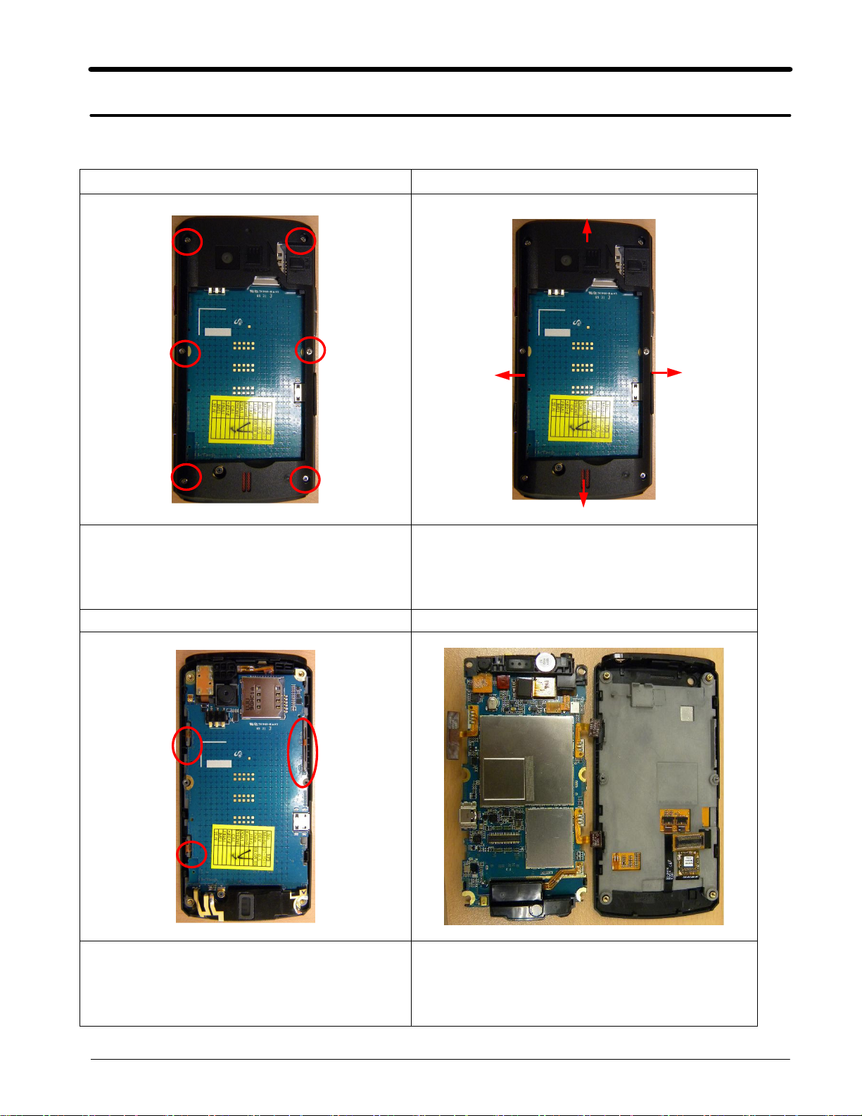
Unscrew6points of the Rear.
③
②
④
1) Put up the upper side of the REAR with
decomposition tool or hand, then disassemble
the Rear
①→②→③→④
①
Detach the Key FPCB,
1)
34
Detach the board from front
2)
11-1
SAMSUNG Proprietary-Contents may change without notice
This Document can not be used without Samsung's authorization
Page 2
Disassembly and Assembly Instructions
56
Detach the FPCB connector point from board
1)
using the tweezers.
Caution
※
Not to scratch or damage the FPCB.
1)
78
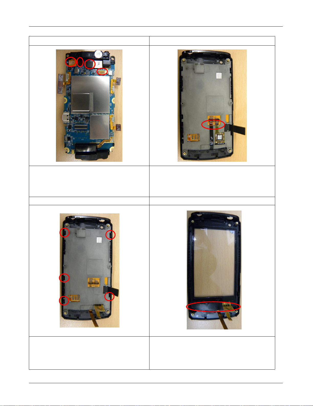
Detach the FPCBs
1)
Left:Key FPCB, Right:TSP FPCB)
(
Detach the bracket from the front.
1)
Caution
※
Push the5hooks carefully.
1)
SAMSUNG Proprietary-Contents may change without notice
This Document can not be used without Samsung's authorization
Detach the key.
1)
11-2
Page 3

Disassembly and Assembly Instructions
11-2.
1)
Assembly
Attach the key to the Front.
12
Joint the5hooks.
1)
34
Connect the LCD connector and TSP FPCB
1)
connector
Place the power key.
1)
11-3
SAMSUNG Proprietary-Contents may change without notice
This Document can not be used without Samsung's authorization
Page 4

Disassembly and Assembly Instructions
56
Place the Camera&Motor module.
1)
Connect4points.
2)
78
①
②③
Connect the LCD FPCB connector to the
1)
board.
Cover the board on the front Assy.
2)
④
Cover the Rear on the Assy.
1)
Joint the hooks in sequence.
2)
①→②→③→④
SAMSUNG Proprietary-Contents may change without notice
This Document can not be used without Samsung's authorization
11-4
Place the Rear on the Main PBA.
1)
Screw the6points.
2)
 Loading...