

Samsung HZ50W Service manual
DIGITAL CAMERA
SAMSUNG HZ50W
SERVICE
Manual
DIGITAL CAMERA
CONTENTS
1. Product Specification
2. Operation Instruction & Installation
3. Exploded View and Parts List
4. Firmware Update
5. Alignment
6. Block Diagram
7. PCB Diagrams
8. Schematic Diagrams
9. Disassembly and Reassembly

© SAMSUNG Co.,Ltd
Printed in Korea
EC-WB5500

Contents
1. Product Specification
1-1 Specifi cations ...................................................................... 1-1
1-2 Instructions on how to use the memory card ........................... 1-4
1-3 LCD monitor indicator ............................................................ 1-5
1-4 Camera Connection Diagram ................................................. 1-7
1-5 Identifi cation of features ....................................................... 1-8
2. Operation Instruction & Installation
2-1 Software Notes ..................................................................... 2-1
2-2 About the software ................................................................ 2-2
2-3 FAQ ...................................................................................... 2-5
3. Exploded View and Parts List
3-1 CABINET-1 ........................................................................... 3-1
3-2 CABINET-2 ........................................................................... 3-5
3-3 PACKING ITEM ..................................................................... 3-8
4. Firmware update
4-1 Product reset ........................................................................ 4-1
4-2 Upgrade................................................................................ 4-3
5. Adjustment
5-1 Barcode Input ....................................................................... 5-1
5-2 Shading Center Position ADJ ................................................. 5-2
5-3 OIS Offset ADJ ...................................................................... 5-3
5-4 Lens Control (1.75m) ............................................................. 5-4
5-5 Lens Control (Infinity) ............................................................ 5-7
5-6 AWB ADJ .............................................................................5-10
5-7 CCD Defect ADJ ..................................................................5-13
5-8 CCD Black & White ADJ .......................................................5-15

Contents
6. Block Diagram
6-1 Main Block ............................................................................ 6-1
6-2 CCD Block ............................................................................ 6-2
6-3 Lens Block ............................................................................ 6-3
6-4 Power Block .......................................................................... 6-4
6-5 Strobe Block ......................................................................... 6-5
7. PCB Diagrams
7-1 CP1 (TOP) ............................................................................ 7-1
7-2 CP1 (Bottom) ........................................................................ 7-2
7-3 CA1 (Top) ............................................................................. 7-3
7-4 CA1 (Bottom) ........................................................................ 7-4
7-5 ST1 (Top) .............................................................................. 7-5
7-6 ST1 (Bottm) .......................................................................... 7-5
7-7 TB1 (Top) .............................................................................. 7-6
7-8 TB1 (Bottm) .......................................................................... 7-6
7-9 TB2 (Top) .............................................................................. 7-7
7-10 TB2 (Bottm) ........................................................................ 7-7
7-11 TB3 (Top) ............................................................................ 7-8
7-12 TB3 (Bottm) ........................................................................ 7-8

Contents
8. Schematic Diagrams
8-1 CP1 (CAA CCD AFE & DRIVER) ............................................ 8-1
8-2 CP1 (DMA MAIN LCD EVF LENS) .......................................... 8-2
8-3 CP1 (DMB) ........................................................................... 8-3
8-4 CP1 (PWA POWER) .............................................................. 8-4
8-5 CP1 (STA STROBE) .............................................................. 8-5
8-6 CP1 (TCA IMAGE STABLILIZER) ........................................... 8-6
8-7 CA1 (CCD)............................................................................ 8-7
8-8 ST1 (STROBE CAPACITOR) .................................................. 8-8
8-9 TB1 ...................................................................................... 8-9
8-10 TB2 ..................................................................................8-10
8-11 TB3 ....................................................................................8-11
8-12 CP1 (OVERALL WIRING) ...................................................8-12
9. Disassembly and reassembly
9-1 Disassembly of main unit ....................................................... 9-1
9-2 Barrel Disassembly ..............................................................9-12
9-3 Barrel Assembly ..................................................................9-19

Memo
1. Product Specification
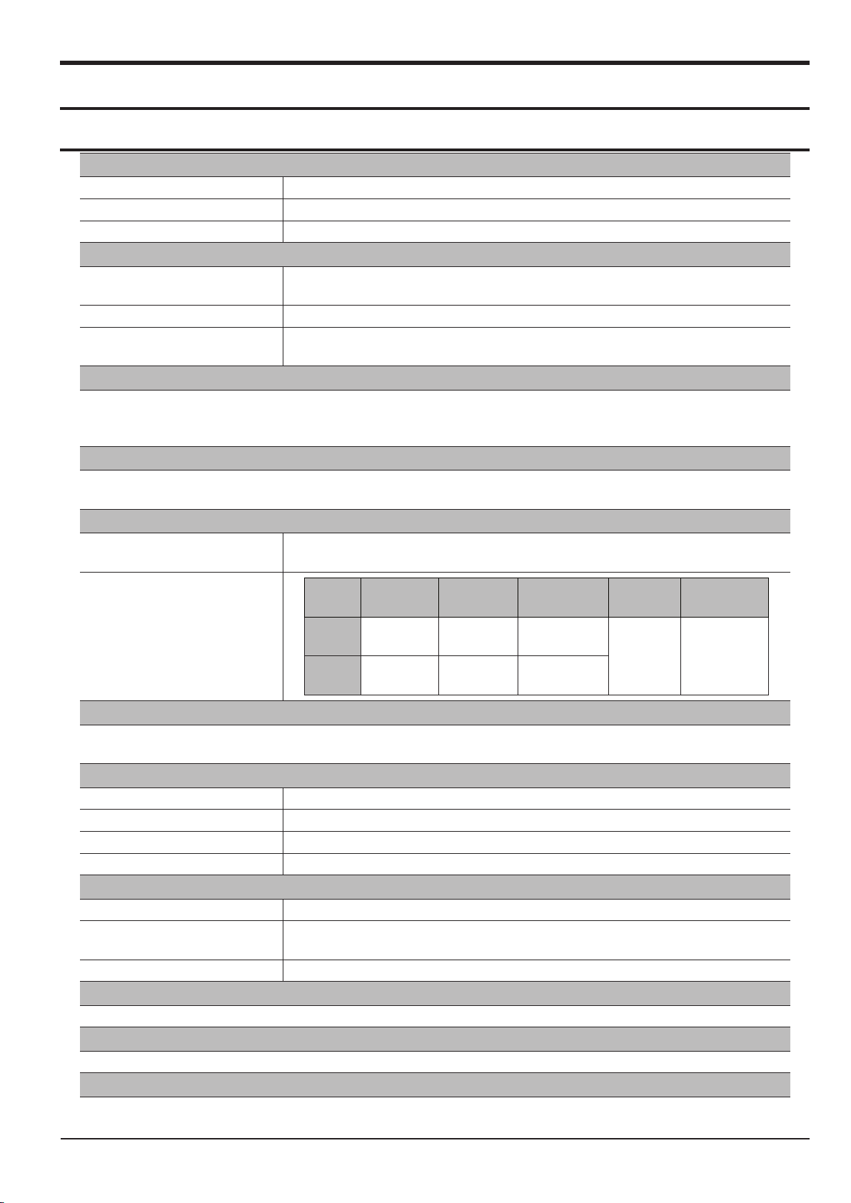
1-1 Specifi cations
Image Sensor
Type 1/2.33”(7.83mm) CCD
Effective Pixel Approx. 13.8 Mega-pixel
Total Pixel Approx. 14.5 Mega-pixel
Lens
Focal Length
F No. F2.8(W) ~ F5.0(T)
Digital Zoom
Image Stabilization
Dual IS (OIS + DIS)
*OIS (Optical Image Stabilization),
DIS (Digital Image Stabilization)
LCD Monitor
3.0”(7.62cm) color TFT LCD (230,000 dots)
Viewnder (EVF) : 0.24” color TFT LCD (230,000 dot)
Focusing
Type
Schneider-Kreuznach Lens
f = 4.6 ~ 119.6mm (35mm lm equivalent : 26 ~ 676mm), 26X Zoom
· Still Image mode :1.0X ~ 5.0X
· Play mode : 1.0X ~ 13.4X (depends on image size)
TTL auto focus (Multi AF, Center AF, Selection AF,
Tracking AF, Face Detection AF)
Product Specication
Focus
range
Focus
range
Wide
Tele
Normal Auto Macro Macro
80cm ~
Innity
170cm ~
Innity
10cm ~
Innity
80cm ~
Innity
Shutter
· Program : 1/2 ~ 1/2,000 sec.,
· A·S/Manual/User : 16 ~ 1/2,000 sec. (Continuous, AEB : 1/4 ~ 1/2,000 sec.)
Exposure
Control Program AE
Metering Multi, Spot, Center-weighted, Face Detection AE
Compensation ±2EV (1/3EV steps)
ISO Auto, 64, 100, 200, 400, 800, 1600, 3200(5M), 6400(3M)
Flash
Modes Auto, Auto & Red-eye reduction, Fill-in ash, Slow sync, Flash off, Red Eye Fix
Range
Recharging Time Approx. 5 sec
· Wide : 0.3 ~ 6.0 m
· Tele : 0.8 ~3.0 m (ISO Auto)
Sharpness
Soft+, Soft, Normal, Vivid, Vivid+
White Balance
Auto, Daylight, Cloudy, Fluorescent_H, Fluorescent_L, Tungsten, Custom
Voice Recording
· Voice Recording (maximum 5 hours at once)
· Voice Memo in Still Image (max. 10 sec.)
10cm ~ 80cm
80cm ~ 150cm
Super
Macro
1 ~ 10cm 10cm ~ Innity
Manual
Focus
SAMSUNG
This Document can not be used without Samsung's authorization
1-1
Product Specication
1-2
This Document can not be used without Samsung's authorization
SAMSUNG
Date Imprinting
Date, Date & Time, Off (user selectable)
Shooting
· Mode : Smart Auto, Program, A·S, Manual, Night, Beauty Shot, Scene, User1, User2
· Scene : Frame Guide, Portrait, Children, Landscape, Close Up, Text, Sunset, Dawn,
Backlight, Fireworks, Beach & Snow
Still Image
Movie Clip
· Smart Auto : Portrait, Night Portrait, Night, Backlight Portrait, Backlight, Landscape, White,
Macro, Macro Text, Tripod, Action, Sunset, Blue Sky, Natural Green,
Macro Color, Macro Portrait
· Shooting : Single, Continuous, High Speed, Motion Capture, AEB
· Self-timer : 10 sec., 2 sec., Double
· With Audio or without Audio (user selectable, recording time : max 20min)
· Size : 1280x720HQ(30FPS & 15FPS),
640x480(30FPS & 15FPS),
320x240(60FPS & 30FPS & 15FPS)
· Movie Editing (Embedded): Pause during recording, Still Image Capture, Time Trimming
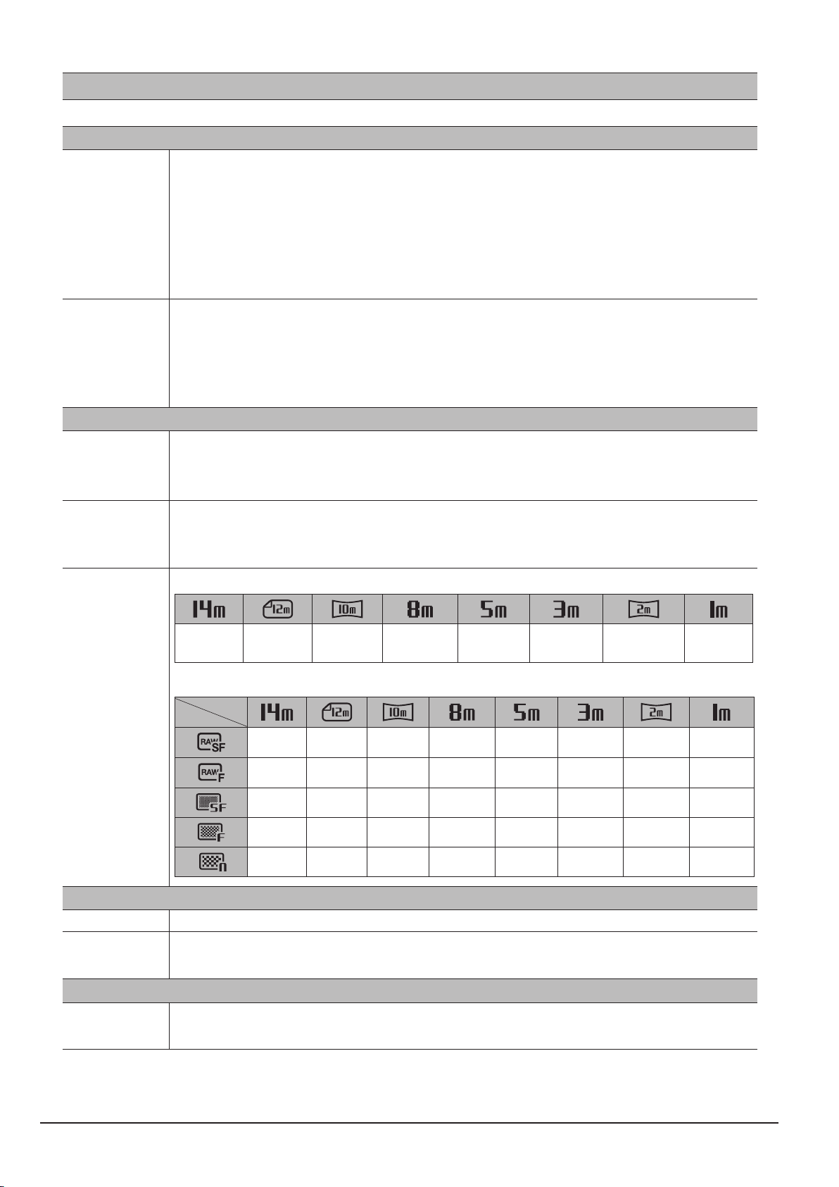
Storage
· Internal memory : About 8MB ash memory
Media
· External memory (Optional) : SD card (Up to 2GB guaranteed)
SDHC card (Up to 32GB guaranteed)
· Still Image : RAW (DNG1.1), JPEG (DCF), EXIF 2.21, DPOF 1.1, PictBridge 1.0
File Format
Storage
· Movie Clip : MP4 (H.264(MPEG4.AVC))
· Audio : WAV
- Image Size
4288x
3216
- Capacity (1GB Size)
4288x
2848
29 - - - - - - -
33 - - - - - - -
116 131 154 199 311 487 716 1640
191 215 252 324 502 779 1113 2397
285 321 375 479 733 1113 1558 3116
4288x
2416
3264x
2448
2592x
1944
Effect
Effect Photo Style Selector, Smart Filter, Image Adjust (Sharpness, Contrast, Saturation)
2048x
1536
1920x
1080
1024x
768
Image Play
Editing
Type
Resize, Rotate, Photo Style Selector, Smart Filter, Image Adjust (ACB, Face
Retouch, Red Eye Fix, Brightness, Contrast, Saturation, Add Noise)
Single image, Thumbnails, Smart Album,
Multi slide show, Movie Clip

Product Specication
SAMSUNG
This Document can not be used without Samsung's authorization
1-3
Interface
Digital output connector USB 2.0
Audio
Microphone: Stereo,
Internal Speaker: Mono
Video output
DC power input connector 4.4V
· AV : NTSC, PAL (user selectable)
· HDMI (Built-in, D-type Standard)
Power Source
Rechargeable battery SLB-11A, 3.8V (1130mAh)
Dimensions(W x H x D)
116.1×82.8×91.1mm
(excluding protrusions)
Weight
Approx. 396g (without battery and card)
Operating Temperature
0 ~ 40°C
Operating Humidity
5 ~ 85%
Software
Intelli-studio, Adobe Reader, Samsung RAW Converter
Product Specication
1-4
This Document can not be used without Samsung's authorization
SAMSUNG
Card pins
Write protect switch
Label
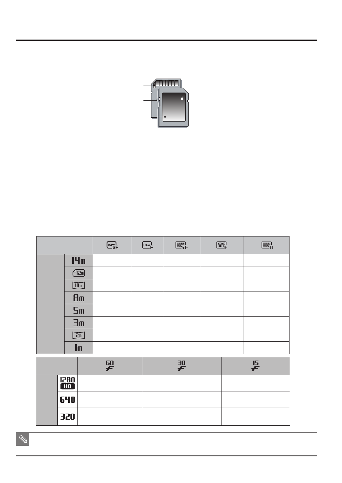
1-2 Instructions on how to use the memory card
The camera can use SD/SDHC Memory Cards and MMC (Multi Media Cards).
Fig. 1-1 SD (Secure Digital) memory card
● The SD/SDHC memory card has a write protect switch that prevents image files from being
deleted or formatted. By sliding the switch to the bottom of the SD/SDHC memory card, the data
will be protected. By sliding the switch to the top of the SD/SDHC memory card, the data protection
will be cancelled.
● Slide the switch to the top of the SD/SDHC memory card before taking a picture.
When using a 1GB SD memory, the speci ed shooting capacity will be as follows. These gures are
approximate as image capacities can be affected by variables such as subject matter and memory card type.
<Table 1-1>
Recorded
image size
Still
image
29 33 116 191 285
- - 131 215 321
- - 154 252 375
- - 199 324 479
- - 311 502 733
- - 487 779 1113
- - 716 1113 1558
- - 1640 2397 3116
Recorded
image size
Movie
clip
■ The zoom button doesn’t use during the movie recording.
■ The recording times can be changed by the zoom operation.
■ You can record videos of up to 4GB or 2hours each.
- 12'58'' 25'18''
- 41'31'' 01:38'30''
01:29'48'' 02:38'14'' 03:23'03''
Product Specication
SAMSUNG
This Document can not be used without Samsung's authorization
1-5
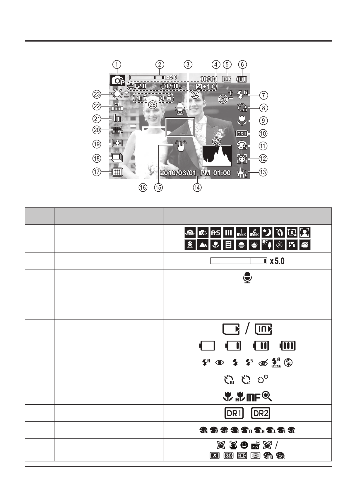
1-3 LCD monitor indicator
■ The LCD monitor displays information about the shooting functions and selections.
Fig. 1-2
No. Description Icons
q
w
e
Optical / Digital Zoom bar / Digital Zoom rate
Number of available shots remaining
Recording mode
Voice Memo
00001
r
t
y
u
Remaining time
Memory card icon / Internal memory icon
Battery
Flash
00:00:00
i
o
a
s
d
Self-timer
Macro
Dynamic Range
Photo Style Selector
Face Detection
Product Specication
1-6
This Document can not be used without Samsung's authorization
SAMSUNG
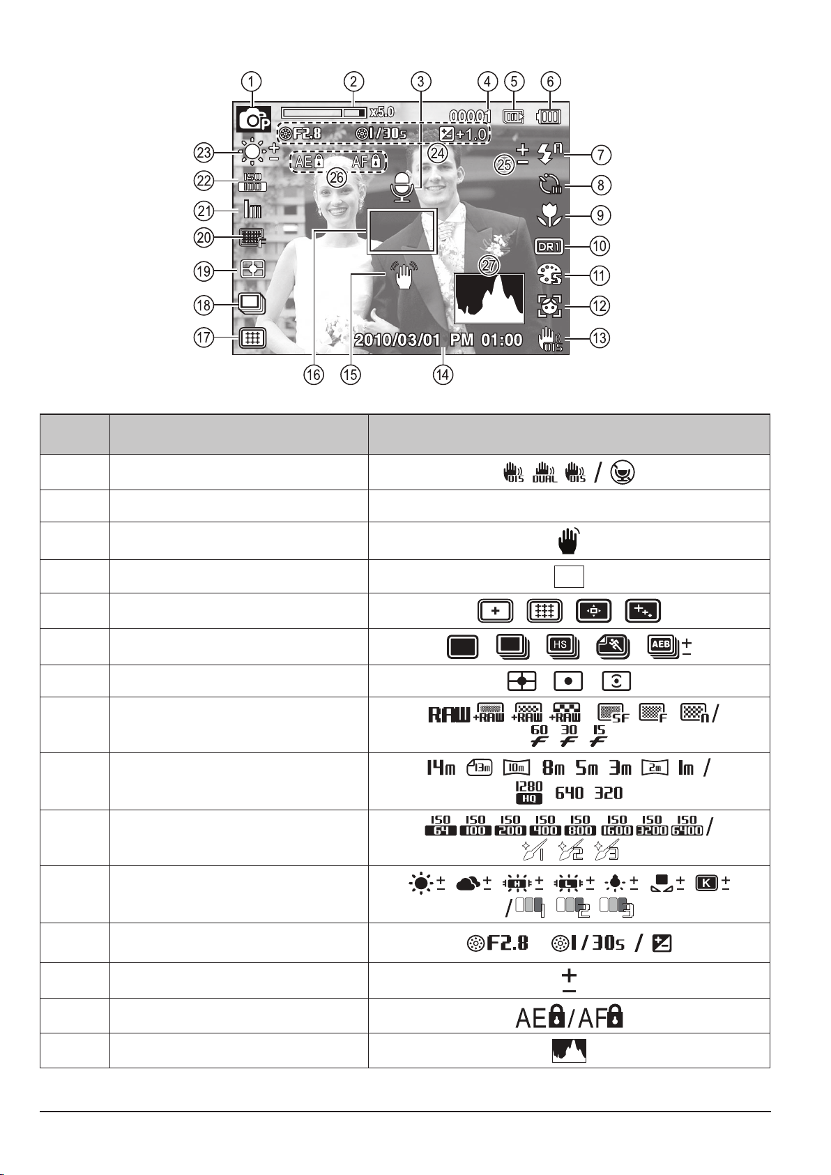
Fig. 1-3
No. Description Icons
f
g
h
j
k
l
;
2)
2!
2@
Camera shake compensation / Without Sound
Date / Time
Camera shake Warning
Auto Focus Frame
Auto Focus type
Drive mode
Metering
Image Quality / Frame Rate
Image Size
ISO / Face Retouch
2010/03/01 PM 01:00
2#
2$
2%
2^
2&
White Balance / Face Tone
Aperture Value/Shutter Speed/
Exposure compensation
Flash EVC
Locking the Exposure/ Locking the Focus
Histogram
Product Specication
SAMSUNG
This Document can not be used without Samsung's authorization
1-7
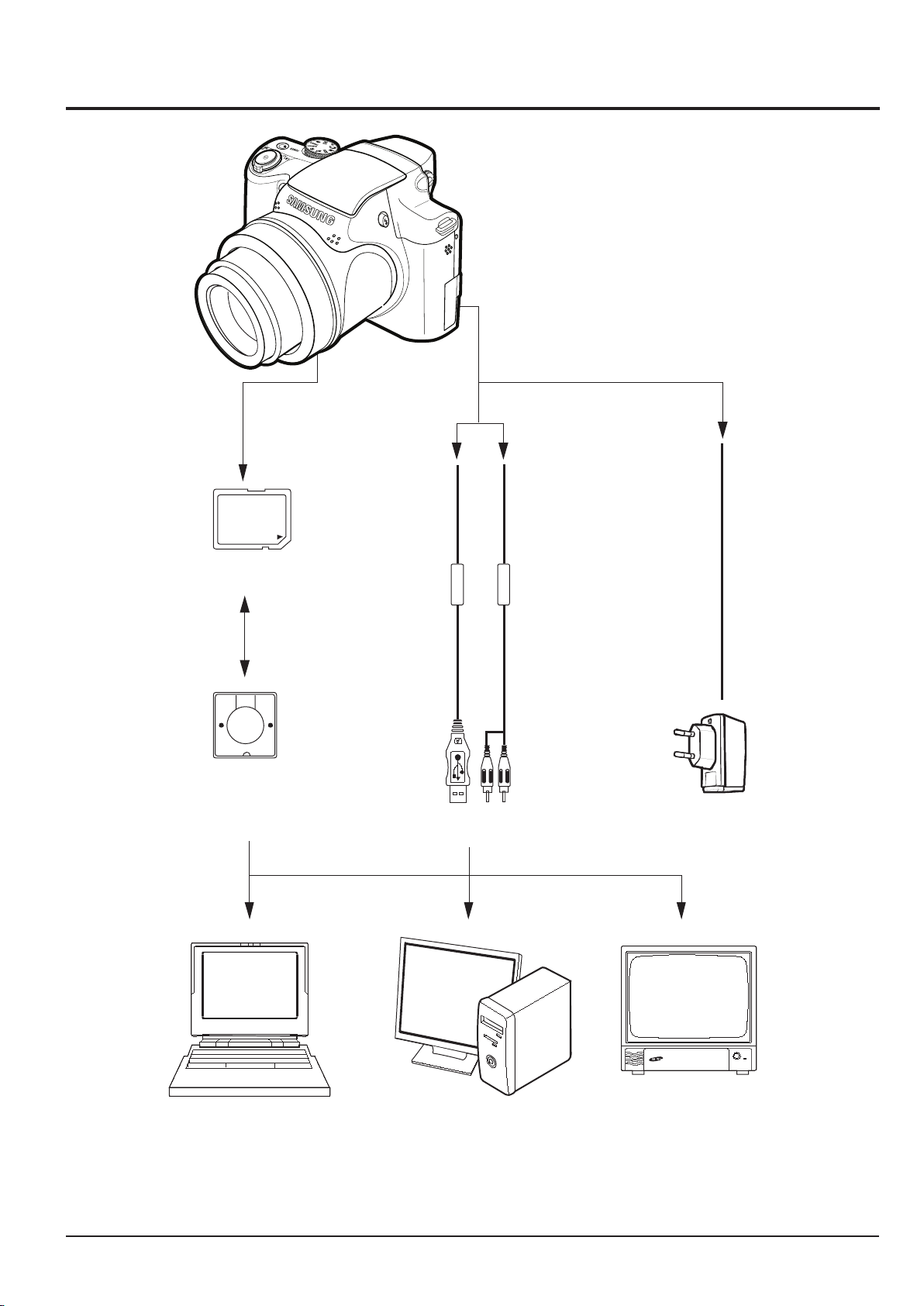
1-4 Camera Connection Diagram
Card Reader
SD Memory
USB Cable
AV Cable
TV Monitor
PC(OS: Windows)/
Mac(OS 9, OS X)
Lap top Computer
AC Adaptor
Fig. 1-4 Camera Connection Diagram
Product Specication
1-8
This Document can not be used without Samsung's authorization
SAMSUNG
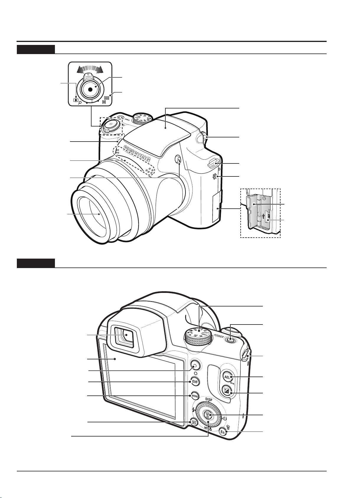
Microphone
AF sensor/
Self-timer lamp
Lens
Flash pop-up button
(p.33)
Built-in À ash (p.33)
Speaker
Hook for neck strap (p.10)
Diopter adjustment lever
(p.33)
Terminal cover
USB / AV / DC
terminal
Zoom T Lever
(Digital zoom)
Zoom W Lever (Thumbnail)
Shutter button
LCD monitor
Electronic View nder (EVF)
(p.36)
Play mode button
Smart dial (p.11)
EVF/LCD button
(p.35)
Video shooting button
MENU button
Mode Dial
POWER button
Fn / Delete button
Hook for neck strap
AE lock/image protection
button (p.34)
Exposure compensation
button (p.35)
OK/AF point button
(p.37)
1-5 Identifi cation of features
Front & Top
Back
Fig. 1-5 Front & Top
Fig. 1-6 Back
Product Specication
SAMSUNG
This Document can not be used without Samsung's authorization
1-9
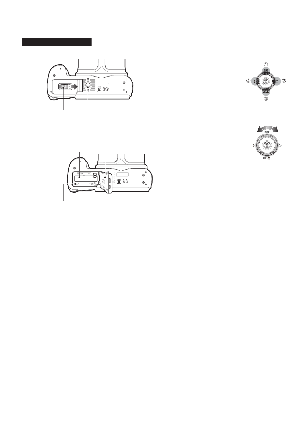
Bottom& Smart dial
Bottom
Identification of features
Tripod socket
Battery chamber
cover lever
Push the battery chamber cover lever in the direction of the arrow to
open the battery chamber cover.
Battery holder
Battery chamber cover
Memory card slot
Battery chamber
Smart dial
Ŷ When pressing the Smart Dial
• Move UP/DOWN /LEFT/RIGHT
• Execute options in the shooting mode:
c
Change the display
d
Change the timer option
e
Change the close-up shooting option
f
Change the ash option
Ŷ When turning the Smart Dial
• Move option or menu
• Adjust the shutter speed, aperture value,
exposure value and set the automatic exposure bracketing (AEB) area in the shooting
mode.
• Search les in the playback mode.
Fig. 1-7 Bottom& Smart dial

Product Specication
Memo
1-10
This Document can not be used without Samsung's authorization
SAMSUNG
2. Operation Instruction & Installation
2-1 Software Notes
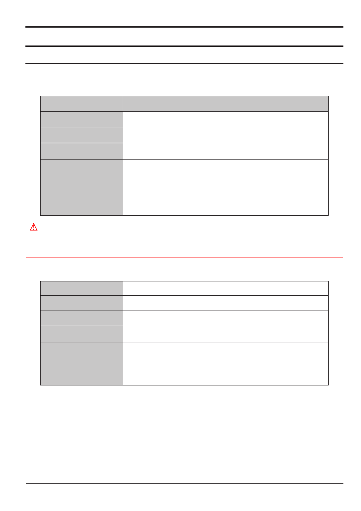
2-1-1 System Requirements
<Table 2-1 For Windows>
Item Requirements
Operation Instruction & Installation
CPU
Intel® Pentium®4 3.2 GHz or higher
AMD Athlon™ FX 2.6 GHz or higher
RAM 512 MB or more (1 GB or more recommended)
OS Windows XP/Vista/7
● USB port
● CD-ROM drive
● nVIDIA Geforce 7600GT or higher
Others
Ati X1600 series or higher
● 1024 X 768 pixels, 16-bit color display compatible
monitor (1280 X 1024 pixels, 32-bit color display recommended)
● Microsoft DirectX 9.0c or later
Caution
■ It is not compatible with Windows XP and Vista 64-bit Edition.
■ Samsung is not responsible for any defects or damages caused by the use of unauthorized computer
including an assembled PC.
<Table 2-2 For Macintosh>
CPU Power Mac G3 or later
RAM Minimum 256MB RAM (Over 512MB recommended)
OS Mac OS 10.4 or later
Available hard disk space
The other
Minimum 256MB RAM
(Over 512MB recommended)
●
USB port
●
CD-ROM Drive
●
1024x768 Pixels, 16bit color
display compatible monitor (24bit color display recommended)
SAMSUNG
This Document can not be used without Samsung's authorization
2-1
Operation Instruction & Installation
2-2
This Document can not be used without Samsung's authorization
SAMSUNG
2-2 About the software
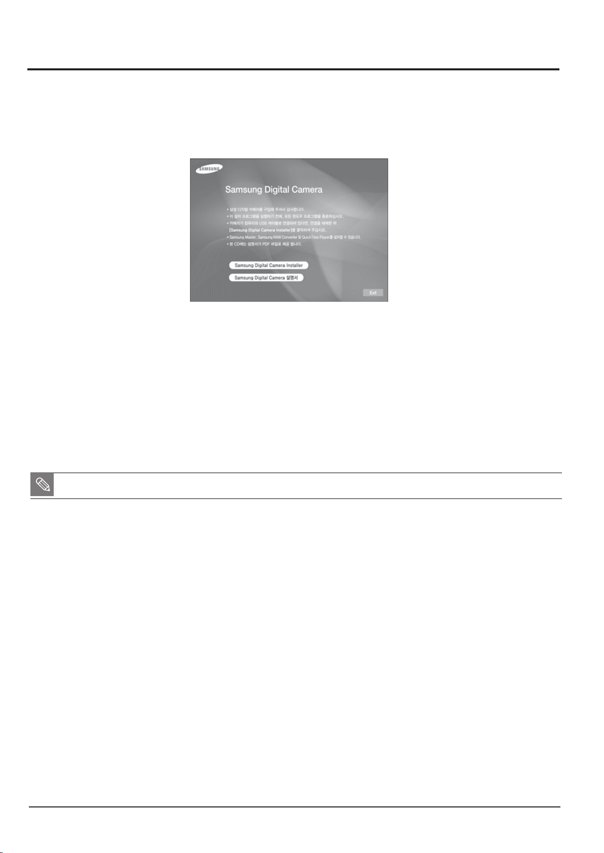
2-2-1 Installing program
q Insert the installation CD in a compatible CD-ROM drive.
w When the setup screen is displayed, click Samsung Digital Camera Installer to start installation.
Fig. 2-1
e Select programs to install and follow the onscreen instructions.
r Click Exit to complete the installation and restart your computer.
2-2-2 Transferring les by connecting the camera as a removable disk
1. You can connect the camera to your computer as a removable disk.
■ If the camera fails to connect, a pop-up window will appear. Select Computer.
q
Connect the camera to your computer with the USB cable.
w Turn on the camera.
• The computer recognizes the camera automatically.
e On your computer, select My Computer → Removable Disk → DCIM → 100PHOTO.
r Select the les you want and drag or save them to your computer.
Operation Instruction & Installation
SAMSUNG
This Document can not be used without Samsung's authorization
2-3
1
7
8
2 3 4 5
6
13
9
14
15
11
12
10
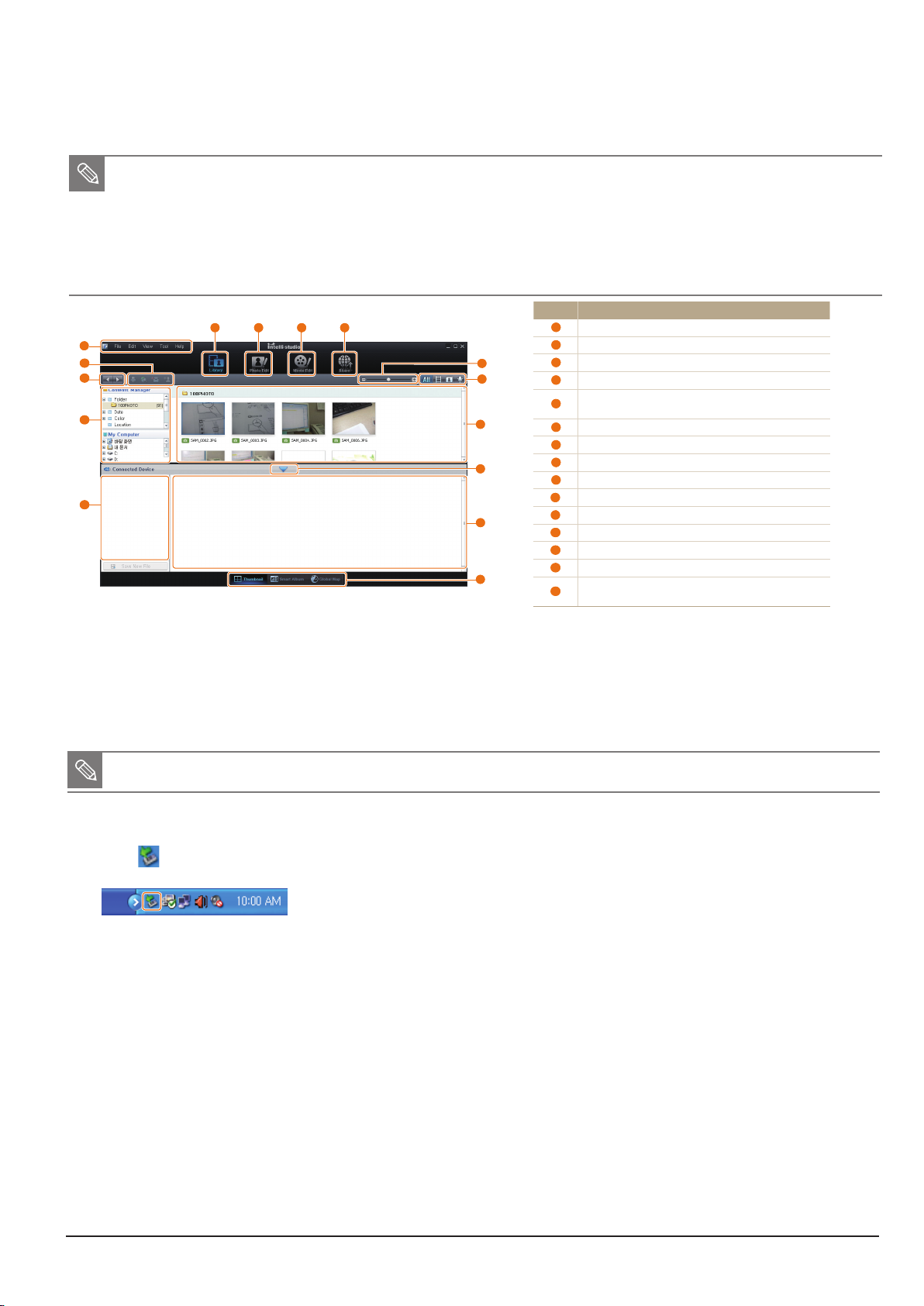
Transferring files to your computer (for Windows)
Transferring files by connecting the camera
as a removable disk
You can connect the camera to your computer as a removable
disk.
In Shooting or Playback mode, press [1 m
].
Select
2
Settings PC SoftwareOff.
Turn off the camera.
3
Connect the camera to your computer with the USB
4
cable.
You must plug the end of the cable with the indicator light (S) into
your camera. If the cable is reversed, it may damage your files. The
manufacturer is not responsible for any loss of data.
Icon Description
1
Open menus
2
Display files in the selected folder
3
Change to the Photo edit mode
4
Change to the Video edit mode
5
Change to the Sharing mode (You can send files by email
or upload files to websites, such as Flickr or YouTube.)
6
Enlarge or reduce the thumbnails in the list
7
Select a file type
8
View files of the selected folder on your computer
9
Show or hide files of the connected camera
10
View files of the selected folder on the camera
11
View files as thumbnails, in Smart Album, or on a map
12
Browse folders in the connected device
13
Browse folders in your computer
14
Move to the previous or next folder
15
Print files, view files on a map, store files in My Folder, or
register faces
2-2-3 Using Intelli-studio
1. Intelli-studio is a built-in program that allows you to play back and edit les. You can also upload les to websites, such as Picasa or
YouTube. For details, select Menu
→
Help in the program.
■ If you install Intelli-studio on your computer, the program will launch more quickly. To install the program, select Menu
→
Install Intelli-studio on PC.
■ You cannot edit les directly on the camera. Transfer les to a folder on your computer before editing.
■ You cannot copy les in your computer to the camera.
■ Intelli-studio supports the following formats:s
- Videos: MP4 (Video: H.264, Audio: AAC), WMV (WMV 7/8/9)
- Photos: JPG, GIF, BMP, PNG, TIFF
2-2-4 Disconnecting the camera (for Windows XP)
1. The way to disconnect the USB cable for Windows Vista/7 is similar.
■ The camera may not be removed safely when Intelli-studio is running. End the program before disconnecting the camera.
q
If the status lamp on your camera is blinking, wait until it stops.
w
Click on the tool bar at the bottom right of your PC screen.
e
Click the pop-up message.
r
Remove the USB cable.
Fig. 2-2
Operation Instruction & Installation
2-4
This Document can not be used without Samsung's authorization
SAMSUNG
2-2-5 Transferring les using Samsung RAW Converter
1. This software is only compatible with Windows OS. This software is only compatible with Windows XP and Vista.
q To start the program, click [Start → All Programs → Samsung RAW Converter →Samsung RAW Converter]
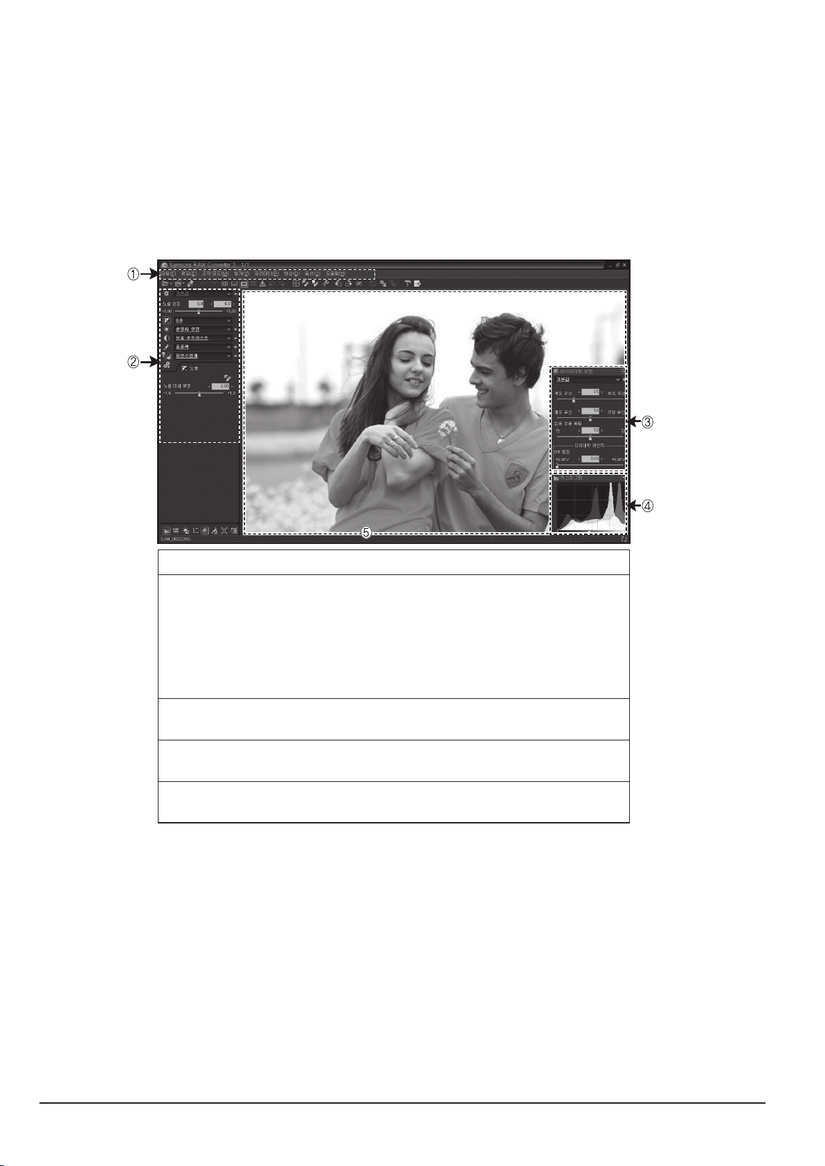
2-2-6 Using Samsung RAW Converter
1. Using the Samsung RAW Converter, you can develop RAW les after editing them as you like. You can also edit JPEG or TIFF les
in the same way you edit the RAW les.
q
Menu bar
w
Image editing tools
[Exposure bias] : Compensates the exposure value.
[White balance] : Adjusts the white balance value.
[Tone] : Adjusts the contrast.
[Color] : Changes the color.
[Sharpness] : Adjusts the sharpness.
[Development] : Previewing is available for the nal output.
e
Highlight controller
Adjusts the saturation and highlights of the selected image.
r
Histogram
Displays the color layers of the selected image.
t
Preview window
Displays the selected image.
Fig. 2-4

Operation Instruction & Installation
SAMSUNG
This Document can not be used without Samsung's authorization
2-5
2-3 FAQ
■ Please check the following if the USB connection malfunctions.
Case 1
Case 2
USB cable is not connected or it is not the supplied USB cable.
Q
Connect the supplied USB cable.
A
The camera is not recognised by your PC. Sometimes, the camera may appear under
Q
[Unknown Devices] in Device Manager.
Turn off the camera, remove the USB cable, plug in the USB cable again, and then turn on the camera.
A
Case 3
Case 4
Case 5
There is an unexpected error during le transfer.
Q
Turn the camera power off and on again. Transfer the le again.
A
When using the USB hub.
Q
There may be a problem in connecting the camera to the PC through the USB hub if the PC and the hub are
A
not compatible. Wherever possible, connect the camera to the PC directly.
Are other USB cables connected to the PC?
Q
The camera may malfunction when it is connected to the PC at the same time as another USB cable.
A
In this case, disconnect the other USB cable, and connect only one USB cable to the camera.

Operation Instruction & Installation
Case 6
When I open the Device Manager (by clicking Start -> (Settings) -> Control Panel -> (Performance and Maintenance)
Q
-> System -> (Hardware) -> Device Manager), there are Unknown Devices or Other Devices entries with a yellow
question mark(?) beside them or devices with an exclamation mark(!) beside them.
Right-click on the entry with the question (?) or exclamation (!) mark and select “Remove”. Restart the PC
A
and connect the camera again.
Case 7
In some security programs (Norton Anti Virus, V3, etc.), the computer may not recognise the camera
Q
as a removable disk.
Stop the security programs and connect the camera to the computer. Refer to the security program
A
instructions about how to temporarily disable the program.
Case 8
The camera is connected to the USB port located on the front of the computer.
Q
When the camera is connected to the USB port located on the front of the computer, the computer may not
A
recognise the camera. Connect the camera to the USB port located on the back of the computer.
2-6
This Document can not be used without Samsung's authorization
SAMSUNG
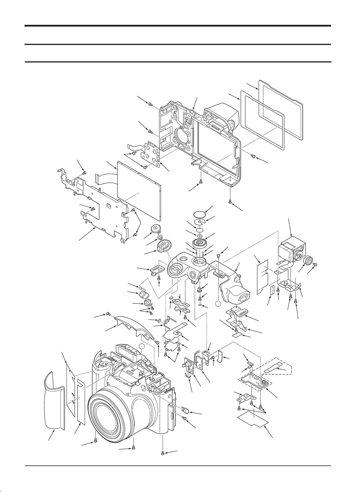
3. Exploded View and Parts List
5376
5370
5372
5080
5374
5084
5085
5375
5086
5086
5080
5373
5371
5375
5078
5086
5085
5077
5377
5378
5377
5378
5079
5079
5770
5082
5081
5083
6
9
11
10
12
16
33
35
39
47
89
90
48
46
45
44
43
28
27
26
25
24
23
22
20
21
29
31
30
88
32
34
31
30
38
37
36
40
41
42
35
7
8
5
2
3
4
A
A
1
18
17
13
14
15
11
19
3-1 CABINET-1
Exploded View and Parts List
SAMSUNG
This Document can not be used without Samsung’s authorization
3-1

Exploded View and Parts List
3-2
This Document can not be used without Samsung's authorization
SAMSUNG
► Available Parts LIST(SA)
Loc. No Parts No Description Q ty Remark
1 AD81-09370A DEC GRIP FRONT 1
2 AD81-09329A ADHESIVE DEC GRIP 1
3 AD81-09369A ADHESIVE DEC GRIP 1
AD81-09619A COVER ST TOP_SAMSUNG WB5500_SL 1 SILVER
AD81-09620A COVER ST TOP_SAMSUNG WB5500_BK 1 BLACK
AD81-09621A COVER ST TOP_VLUU WB5500_SL 1 SILVER
4
AD81-09622A COVER ST TOP_VLUU WB5500_BK 1 BLACK
AD81-09623A COVER ST TOP_SAMSUNG_HZ50W_SL 1 SILVER
AD81-09624A COVER ST TOP_SAMSUNG_HZ50W_BK 1 BLACK
5 AD81-09382A BUTTON ST 1
7 AD81-09368A HOLDER STRAP 1
8 AD81-09625A COMPL PWB,TB-1 1
13 AD81-09215A HOLDER AF 1
14 AD81-09626A COMPL PWB,TB-2 1
15 AD81-09213A DEC AF4 1
17 AD81-09217A HOLDER RELEASE 1
18 AD81-09342A UNIT,CONTROL TOP 1
19 AD81-09227A SPRING ZOOM PLATE 1
20 AD81-09206A BUTTON POWER 1
21 AD81-09212A DEC POWER RING 1
22 AD81-09228A TERMINAL ZOOM 1
23 AD81-09219A HOLDER ZOOM 1
24 AD81-09313A SPRING ZOOM 1
25 AD81-09210A DEC STRAP L 1
26 AD81-09221A KNOB ZOOM 1
27 AD81-09314A SPRING RELEASE 1
28 AD81-09207A BUTTON RELEASE 1
29 AD81-09627A HOLDER MODE DIAL 1
30 AD81-09315A SPRING CLICK 25 2
31 AD81-09205A BALL CLICK VF 2
32 AD81-09628A KNOB MODE DIAL 1
34 AD81-09629A DEC MODE DIAL 1
36 AD81-09214A HOLDER STRAP R 1
37 AD81-09211A DEC STRAP R 1

SAMSUNG
This Document can not be used without Samsung’s authorization
3-3
Exploded View and Parts List
► Available Parts LIST(SA)
Loc. No Parts No Description Q ty Remark
AD81-09630A CABINET TOP_SL 1 SILVER
38
AD81-09631A CABINET TOP_BK 1 BLACK
40 AD81-09632A HOLDER EVF 1
41 AD81-09222A KNOB EVF 1
42 AD81-09353A ASSY,UNIT EVF SV 1
43 AD81-09633A ASSY,HOLDER LCD 1
44 AD81-09634A LCD 1
45 AD81-09234A UNIT,CONTROL BACK 1
AD81-09635A ASSY,CABI BACK_SL 1 SILVER
46
AD81-09636A ASSY,CABI BACK_BK 1 BLACK
48 AD81-09233A DEC MONITOR 1
88 AD81-09637A HOLDER DIAL 1

Exploded View and Parts List
3-4
This Document can not be used without Samsung's authorization
SAMSUNG
► Unavailable Parts LIST(SNA)
Loc. No Description Q ty Remark
6
9 FLEXIBLE PWB CP1&TB1 1
10 ADHESIVE SW ROTARY 1
11 SPACER STRAP 3
12 SPACER POWER LED 1
16 SPACER DEC AF 1
33 ADHESIVE MODE DIAL 1
35 SPACER HL EVF H 1
39 SPACER HL EVF 1
47 ADHESIVE DEC MONITOR 1
89 SPACER KNOB DIAL 1
90 SPACER HOLDER AF 1
SPACER TOP
1
SAMSUNG
This Document can not be used without Samsung’s authorization
3-5
Exploded View and Parts List
B
B
49
50
51
52
53
54
55
56
57
58
59
60
61
62
63
64
65
66
67
68
69
70_2
70_3
72
70_1
74
75
76
77
78
79
80
81
82
83
84
85
86
5170
5073
5073
5070
5075
5071
5075
5074
5072
5076
5076
5170
56
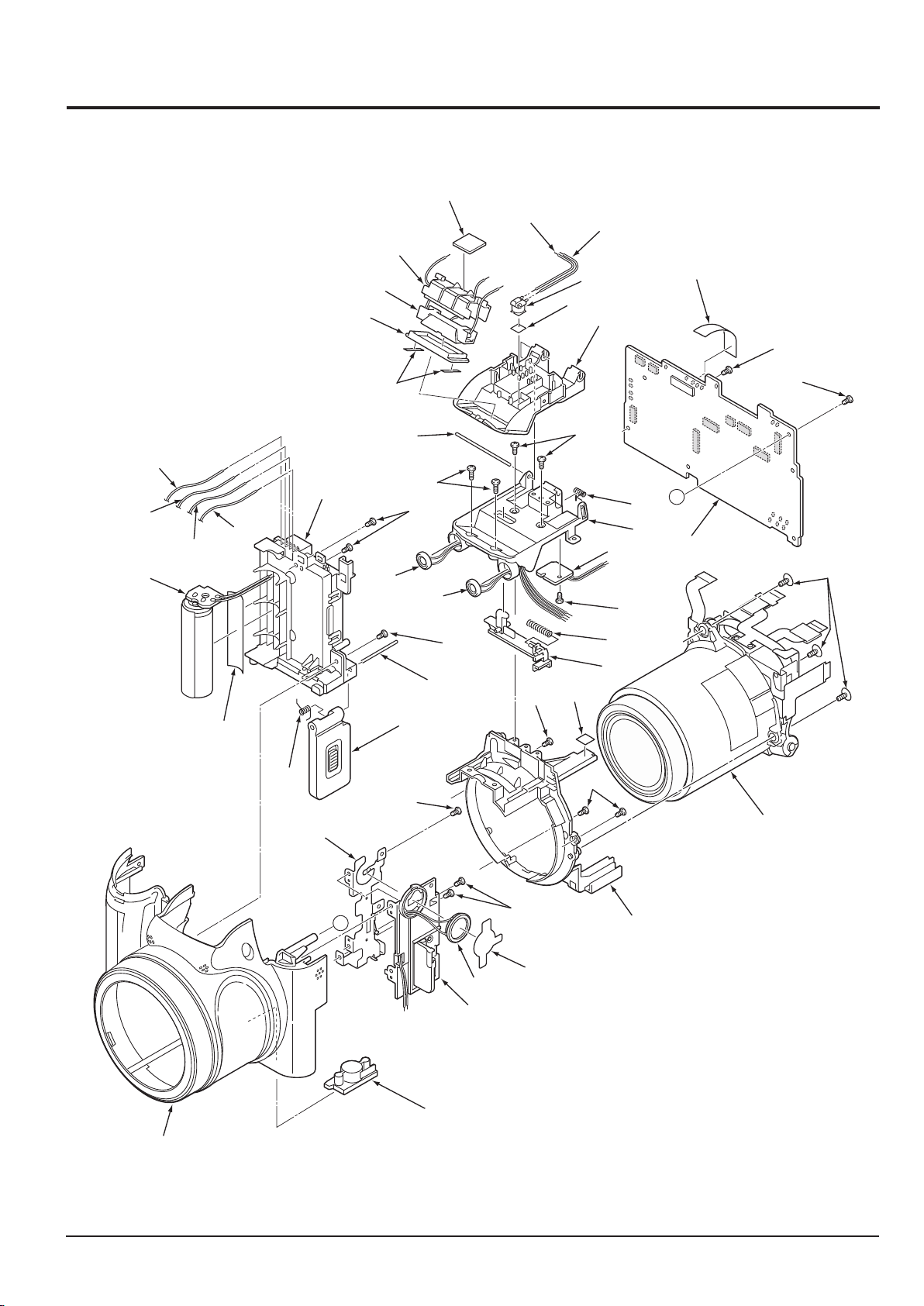
3-2 CABINET-2

Exploded View and Parts List
3-6
This Document can not be used without Samsung's authorization
SAMSUNG
► Available Parts LIST(SA)
Loc. No Parts No Description Q ty Remark
49 AD81-09638A ASSY,CABI FRON_SL 1 SILVER
49 AD81-09639A ASSY,CABI FRONT_BK 1 BLACK
50 AD81-09372A STAND 1
51 AD81-09640A ASSY,COVER JACK_SL 1 SILVER
51 AD81-09641A ASSY,COVER JACK_BK 1 BLACK
53 AD81-09642A SPEAKER 1
54 AD81-09643A HOLDER SIDE 1
55 AD81-09367A HOLDER CHASSIS 1
57 AD81-09644A ASSY_BARREL 1
58 AD81-09645A ASSY_COVER BATTERY_SL 1 SILVER
58 AD81-09646A ASSY_COVER BATTERY_BK 1 BLACK
59 AD81-09320A SPRING COVER BATT 1
60 AD81-09378A SHAFT COVER BATT 1
62 AD81-09647A COMPL PWB,ST-1 1
63 AD81-09380A COMPL,HOLDE R BATT 1
68 AD81-09376A LEVER ST 1
69 AD81-09321A SPRING LEVER ST 1
72 AD81-09649A COMPL PWB,TB-3 1
74 AD81-09377A SPRING POP ST 1
75 AD81-09334A SHAFT ST 1
76 AD81-09373A COVER ST BOTTOM 1
77 AD81-09650A TRANS,STEP UP 1
81 AD81-09357A DEC FLASH 1
82 AD81-09340A ASSY,LAMP 1
83 AD81-09374A HOLDER FLASH 1
85 AD81-09651A ASSY_MAIN PCB 1
87 AD81-09652A SPRING COVER PLATE 1
70_1 AD81-09375A HOLDER ST BOTTOM 1
70_2 AD81-09343A MICROPHONE1 1
70_3 AD81-09344A MICROPHONE2 1

SAMSUNG
This Document can not be used without Samsung’s authorization
3-7
Exploded View and Parts List
► Unavailable Parts LIST(SNA)
Loc. No Description Q ty Remark
52
56 ADHESIVE TRIG 2
61 ADHESIVE CONDENSER 1
64 ASSY,WIRE BATT 1
65 ASSY,WIRE BAT_T 1
66 ASSY,WIRE BATT+ 1
67 ASSY,WIRE BAT_ID 1
78 WIRE TRIG IN 1
79 WIRE TRIG GND 1
80 ADHESIVE DEC FLASH 2
84 SPACER FLASH 1
86 SPACER CP1 1
91 SPACER DEC FLASH 1
92 SPACER HOLDER FLASH 1
SPACER SPEAKER
1
Exploded View and Parts List
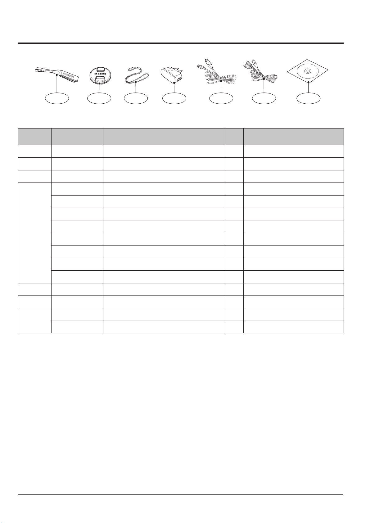
3-3 PACKING ITEM
1-1 1-2 1-3 1-4 1-5 1-6 1-7
► Available Parts LIST(SA)
Loc. No Parts No Description Q ty Remark
1-1 AD63-04525A
1-2 AD67-01588A LENS CAP 1
1-3 AD63-04527A LENS CAP_STRAP 1
4302-001226 LITHIUM-ION_SLB-11A 1
AD44-00146A AC_ADAPTOR_4.6V_EXP(SACE) 1
AD44-00142A AC_ADAPTOR_4.6V_KOR(SACK) 1
AD44-00147A AC_ADAPTOR_4.2V_CHI(SACC) 1
1-4
AD44-00143A AC_ADAPTOR_4.6V_USA(SACS) 1
AD44-00145A AC_ADAPTOR_4.6V_UK(SACU) 1
AD44-00148A AC_ADAPTOR_4.6V_AUS(SACA) 1
AD44-00144A AC_ADAPTOR_4.6V_ARG(SACG) 1
1-5 AD39-00165A 20PIN_USB_Cable_CB20U05A 1
1-6 AD39-00146A 20PIN_AV_CABLE_SCC-AV20 1
AD46-00342A SAMSUNG WB5500(KOR,CHI,EXP) 1
1-7
AD46-00343A SAMSUNG HZ50W(USA) 1
STRAP_WB5000
1
3-8
This Document can not be used without Samsung's authorization
SAMSUNG
 Loading...