


WirelessAudio– Soundbar(Active SpeakerSystem)
ModelNameHW-H355
ModelCodeHW-H355/XU
SERVICE
WirelessAudio–Soundbar
(ActiveSpeakerSystem)
MANUAL
Contents
1.Precaution
2.ProductSpecication
3.Disassembly&Reassembly
4.Troubleshooting
5.PCBDiagram
HW-H355
6.SchematicDiagram
RefertotheservicemanualintheGSPN(seetherearcover)formoreinformation.

Contents
Contents
1.Precaution........................................................................................................................................1−1
1.1.SafetyPrecautions...................................................................................................................1−1
1.2.ServicingPrecautions...............................................................................................................1−3
1.3.PrecautionsforElectrostaticallySensitiveDevices(ESDs)..............................................................1−4
1.4.InstallationPrecautions.............................................................................................................1−5
2.ProductSpecication.........................................................................................................................2−1
2.1.ProductFeature.......................................................................................................................2−1
2.2.Specications..........................................................................................................................2−2
2.3.SpecicationsAnalysis.............................................................................................................2−3
2.4.Accessories............................................................................................................................2−4
2.4.1.SuppliedAccessories...................................................................................................2−4
3.Disassembly&Reassembly................................................................................................................3−1
3.1.OverallDisassemblyandReassembly..........................................................................................3−1
4.Troubleshooting................................................................................................................................4−1
4.1.CheckpointsbyErrorMode.......................................................................................................4−1
4.1.1.NoPower...................................................................................................................4−2
4.1.2.NoSoundOutput(Digital)............................................................................................4−3
4.1.3.NoSoundOutput(Analog)............................................................................................4−7
4.2.MeasurestobetakenwhentheProtectionCircuitoperates...............................................................4−10
4.2.1.AMPPre-InspectionrelatingtoPowerProtection..............................................................4−10
4.3.Initialization&Update.............................................................................................................4−11
4.3.1.HowtochecktheFirmwareversion................................................................................4−11
4.3.2.Howtoinitialize..........................................................................................................4−11
4.3.3.USBUpdateprocedure.................................................................................................4−12
5.PCBDiagram...................................................................................................................................5−1
5.1.WiringDiagram.......................................................................................................................5−1
5.2.MAINPCBTop......................................................................................................................5−2
5.2.1.PinConnection...........................................................................................................5−3
5.2.2.TestPointWaveForm..................................................................................................5−4
5.3.MAINPCBBottom..................................................................................................................5−5
5.3.1.PinConnection...........................................................................................................5−6
5.3.2.TestPointWaveForm..................................................................................................5−7
5.4.VFDPCBTop.........................................................................................................................5−8
5.5.VFDPCBBottom....................................................................................................................5−9
5.5.1.PinConnection...........................................................................................................5−10
5.6.JACKPCBTop.......................................................................................................................5−11
5.6.1.PinConnection...........................................................................................................5−12
5.6.2.TestPointWaveForm..................................................................................................5−13
iCopyright©1995-2013SAMSUNG.Allrightsreserved.

Contents
5.7.JACKPCBBottom..................................................................................................................5−14
5.7.1.PinConnection...........................................................................................................5−15
6.SchematicDiagram...........................................................................................................................6−1
6.1.OverallBlockDiagram.............................................................................................................6−1
6.2.MAIN-1.................................................................................................................................6−2
6.3.MAIN-2.................................................................................................................................6−3
6.4.MAIN-3.................................................................................................................................6−4
6.4.1.TestPointWaveForm..................................................................................................6−5
6.5.MAIN-4.................................................................................................................................6−6
6.6.MAIN-5.................................................................................................................................6−7
6.6.1.TestPointWaveForm..................................................................................................6−8
6.7.VFD......................................................................................................................................6−9
6.8.JACK....................................................................................................................................6−10
6.8.1.TestPointWaveForm..................................................................................................6−11
Copyright©1995-2013SAMSUNG.Allrightsreserved.ii
1.Precaution
DEVICE
UNDER
TES T
LEAKAGE
CUR RE NT
TES TER
TES T ALL
EXPO SED ME TAL
SU RFACES
2-WIRE CORD
ALSO TE S T WITH
PLUG REVERSED
(US ING AC
ADAPTER P LUG
AS R EQ UIRED)
EARTH
GR OUND
(RE ADING
SH OULD NOT BE
ABOVE 0.5m A)
1.Precaution
FollowthesesafetyinstructionswhileservicingtheESDtopreventdamageandtoprotectagainstpotentialhazards
suchaselectricalshockandX-rays.
1.1.SafetyPrecautions
1)Whenreinstallingthechassisanditsassemblies,besuretorestorealloftheprotectivedevices,includingthecontrol
knobsandthecompartmentcovers.
2)Makesurethattherearenocabinetopeningsthroughwhichpeople(particularlychildren)canmakecontactwith
dangerousinternalcomponents.
3)DesignAlterationWarning:
Neveralteroraddtothemechanicalorelectricaldesignoftheunit.
Example:Donotaddauxiliaryaudioorvideoconnectors.Suchalterationsmightcreateasafetyhazard.
Also,anydesignchangesoradditionswillvoidthemanufacturer’swarranty.
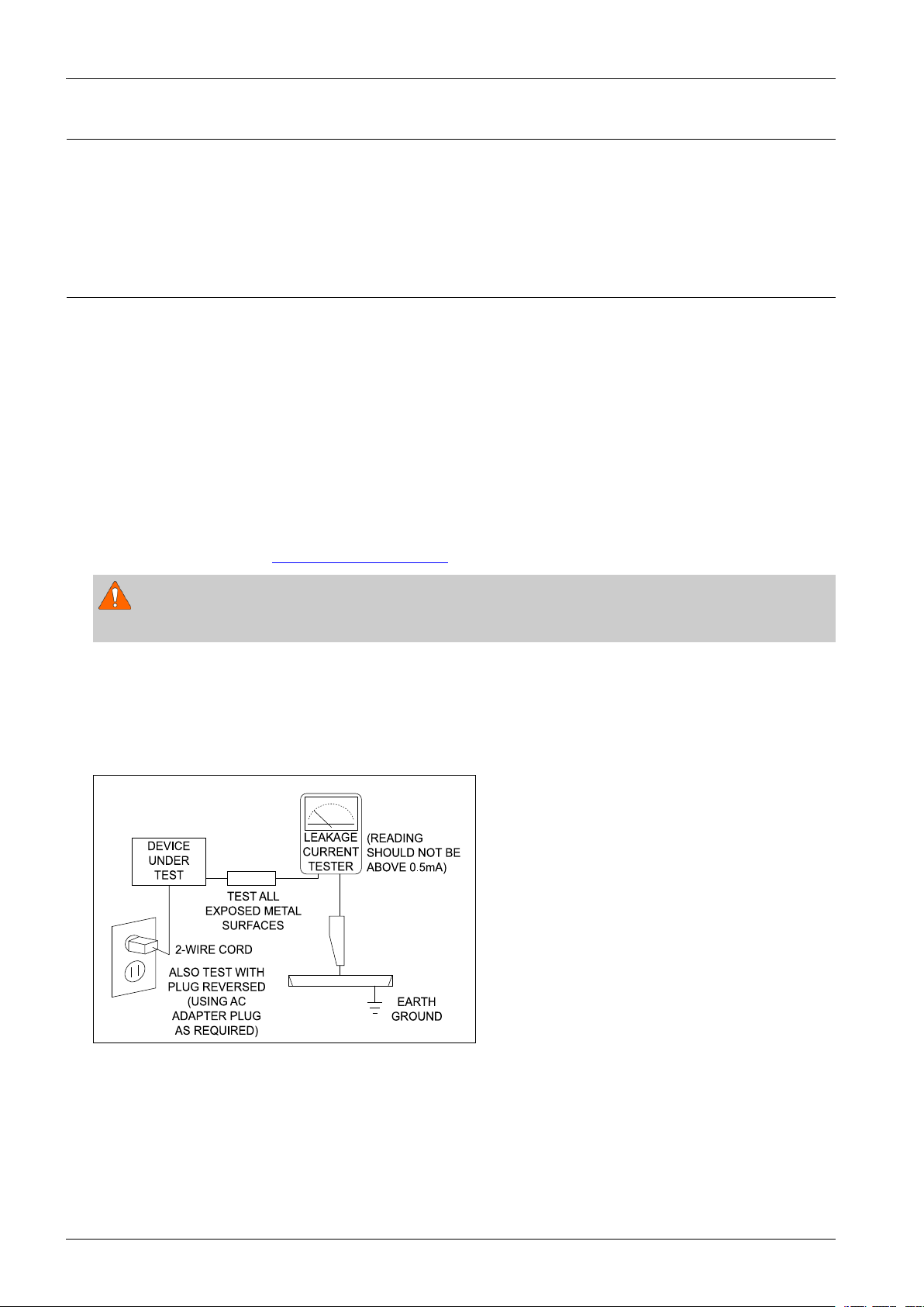
4)LeakageCurrentHotCheckFigure1.1
ACLeakageTest:
WARNING
Donotuseanisolationtransformerduringthistest.Usealeakage-currenttesterorameteringsystemthatcomplies.
Withtheunitcompletelyreassembled,plugtheACcorddirectlyintoaACoutlet.Withtheunit’spowerswitchedfrom
theONtotheOFFposition,measurethecurrentbetweenaknowngroundandallexposedmetalparts.
KnownGrounds-Earth
KnownMetalparts-screwheads,metalcabinets,etc.
Figure1.1ACLeakageTest
1-1Copyright©1995-2013SAMSUNG.Allrightsreserved.
1.Precaution
Ante nna
Term inal
ohm
Expo sed
Meta l Part
Ohmmet er
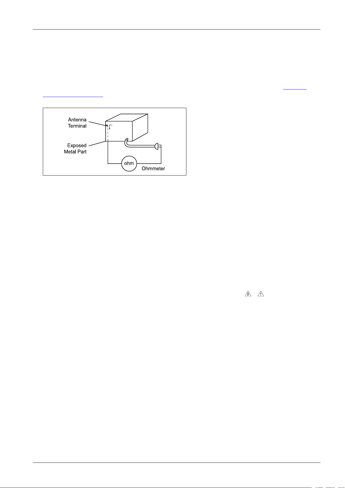
5)InsulationResistanceColdCheck:
(1)Withtheunit’sACplugdisconnectedfromtheACsource,connectanelectricaljumperacrossthetwoACprongs.
(2)SetthepowerswitchtoON.(3)MeasuretheresistancebetweentheshortedACplugandanyexposedmetallicparts.
Example:screwheads,metalcabinets,antennaport,etc.Ifanyoftheexposedmetallicpartshasareturnpathtothe
chassis,themeasuredresistanceshouldbebetween1and5.2megohms.Ifthereisnoreturnpath,themeasured
resistanceshouldbe“innite.”Iftheresistanceisoutsidetheselimits,ashockhazardmightexist.SeeFigure1.2
InsulationResistanceTest
Figure1.2InsulationResistanceTest
6)Components,partsandwiringthatappeartohaveoverheatedorthatareotherwisedamagedshouldbereplacedwith
partsthatmeettheoriginalspecications.Alwaysdeterminethecauseofdamageoroverheating,andcorrectany
potentialhazards.
7)Observetheoriginalleaddress,especiallynearthefollowingareas:Antennawiring,sharpedges,andespeciallytheAC
andhighvoltagepowersupplies.Alwaysinspectforpinched,out-of-place,orfrayedwiring.
Donotchangethespacingbetweencomponentsandtheprintedcircuitboard.ChecktheACpowercordfordamage.
Makesurethatnowiresorcomponentstouchthermallyhotparts.
8)ProductSafetyNotice:
Someelectricalandmechanicalpartshavespecialsafety-relatedcharacteristicswhichmightnotbeobviousfromvisual
inspection.Thesesafetyfeaturesandtheprotectiontheygivemightbelostifthereplacementcomponentdiffersfrom
theoriginal—evenifthereplacementisratedforhighervoltage,wattage,etc.
9)Componentsthatarecriticalforsafetyareindicatedinthecircuitdiagrambyshading,
or.Usereplacement
componentsthathavethesameratings,especiallyforameresistanceanddielectricstrengthspecications.A
replacementpartthatdoesnothavethesamesafetycharacteristicsastheoriginalmightcreateshock,reorother
hazards.
Copyright©1995-2013SAMSUNG.Allrightsreserved.1-2

1.Precaution
1.2.ServicingPrecautions
1)Servicingprecautionsareprintedonthecabinet.Followthem.
2)Alwaysunplugtheunit’sACpowercordfromtheACpowersourcebeforeattemptingto:
(a)Removeorreinstallanycomponentorassembly ,(b)Disconnectanelectricalplugorconnector,(c)Connecta
testcomponentinparallelwithanelectrolyticcapacitor.
3)Somecomponentsareraisedabovetheprintedcircuitboardforsafety.Aninsulationtubeortapeissometimesused.
Theinternalwiringmaybeclampedtopreventcontactwiththermallyhotcomponents.Reinstallallsuchelements
totheiroriginalposition.
4)Afterservicing,alwayscheckthatthescrews,componentsandwiringhavebeencorrectlyreinstalled.Makesurethat
theportionaroundtheservicedparthasnotbeendamaged.
5)ChecktheinsulationbetweenthebladesoftheACplugandaccessibleconductiveparts(examples:metalpanels,
inputterminalsandearphonejacks).
6)InsulationCheckingProcedure:
DisconnectthepowercordfromtheACsource.Connectaninsulationresistancemeter(500V)tothebladesofthe
ACplug.TheinsulationresistancebetweeneachbladeoftheACplugandaccessibleconductiveparts(seeabove)
shouldbegreaterthan1megohm.
7)NeverdefeatanyoftheB+voltageinterlocks.DonotapplyACpowertotheunit(oranyofitsassemblies)unlessall
solid-stateheatsinksarecorrectlyinstalled.
8)Alwaysconnectatestinstrument’sgroundleadtotheinstrumentchassisgroundbeforeconnectingthepositivelead;
alwaysremovetheinstrument’sgroundleadlast.
CAUTION
Firstreadthe“SafetyPrecautions”sectionofthismanual.Ifsomeunforeseencircumstancecreatesaconictbetweenthe
servicingandsafetyprecautions,alwaysfollowthesafetyprecautions.
1-3Copyright©1995-2013SAMSUNG.Allrightsreserved.

1.Precaution
1.3.PrecautionsforElectrostaticallySensitiveDevices(ESDs)
Somesemiconductor(“solidstate”)devicesareeasilydamagedbystaticelectricity.
SuchcomponentsarecalledElectrostaticallySensitiveDevices(ESDs).
Examplesincludeintegratedcircuitsandsomeeld-effecttransistors.
Thefollowingtechniqueswillreducetheoccurrenceofcomponentdamagecausedbystaticelectricity:
1)Immediatelybeforehandlinganysemiconductorcomponentsorassemblies,draintheelectrostaticchargefromyour
bodybytouchingaknownearthground.Alternatively,wearadischargingwrist-strapdevice.(Besuretoremoveit
priortoapplyingpower–thisisanelectricshockprecaution.)
2)AfterremovinganESD-equippedassembly,placeitonaconductivesurfacesuchasaluminumfoiltoprevent
accumulationofelectrostaticcharge.
3)Donotusefreon-propelledchemicals.ThesecangenerateelectricalchargesthatdamageESDs.
4)Useonlyagrounded-tipsolderingironwhensolderingorunsolderingESDs.
5)Useonlyananti-staticsolderremovaldevice.Manysolderremovaldevicesarenotratedas“anti-static”(thesecan
accumulatesufcientelectricalchargetodamageESDs).
6)DonotremoveareplacementESDfromitsprotectivepackageuntilyouarereadytoinstallit.
MostreplacementESDsarepackagedwithleadsthatareelectricallyshortedtogetherbyconductivefoam,aluminum
foilorotherconductivematerials.
7)ImmediatelybeforeremovingtheprotectivematerialfromtheleadsofareplacementESD,touchtheprotectivematerial
tothechassisorcircuitassemblyintowhichthedevicewillbeinstalled.
8)MinimizebodymotionswhenhandlingunpackagedreplacementESDs.Motionssuchasbrushingclothestogether,or
liftingafootfromacarpetedoorcangenerateenoughstaticelectricitytodamageanESD.
Copyright©1995-2013SAMSUNG.Allrightsreserved.1-4

1.Precaution
1.4.InstallationPrecautions
1)Keeptheproductawayfromaheatsourcesuchascandlelight,mosquitorepellentincense,heatingequipment,ordirect
sunlight.Otherwise,thismaycausere.
2)Donotinstalltheproductonaplacethatisshaking,tilted,unstable,orseriouslyvibrating.Theproductmaydroptoget
damagedorinjureaperson.Ifusingtheproductinahighlyvibratingplace,itmaybebrokenorcausere.
3)Whenmovingtheproduct,turnoffthepowerswitchandunplugalltheconnectedcableswiththeproductsuchasthe
powerplugandantennacable.Ifthepowercordisdamaged,thismaycauseelectricshockorre.
4)Secureroomforventilation.Keepatleast10cmofdistancefromtherearwall,andatleast5cmfromeithersidewall.
5)Installingtheproductinaspecialplacelikebelowratherthannormalenvironmentmaycauseseriousqualityconcerns
duetoitsspecialconditions.Ifthisisthecase,makesuretocontactalocalSamsungservicecenterbeforeinstallingthe
product.(Specialplaces:aplacewherealargeamountofdustisaccumulated;wherechemicalsubstancesareused
ortheambienttemperatureistoohighorlow;aplacethatisfullofmoistureorwater;intransportationvehicles
suchasacar;orinpublicplacessuchastheairportorsubwaystationwheretheproductissupposedtooperate
uninterruptedlyforalongtime)
6)Keepthepackagingplasticwrapperoutofchildren'sreach.Ifchildrenplaywithitimproperly,theymaygetsuffocated.
7)Ifinstallingtheproductonadisplaycabinet,shelf,desk,etc.,keeptheproductfromprotrudingonitslowerside.Ifthe
productfalls,itmaybreakorcausephysicalinjury .Useonlythedisplaycabinetorshelfthatfullycoverstheproduct.
8)Ifusinglithiumbatteries,carefullyreadthefollowingprecautions:
NOTE
•Ensurethebatteriesareinsertedintherightdirection.Otherwise,theymaycauseanexplosion.Disposeofusedbatteries
accordingtothemanufacturer'sinstructions.
•Donotexposethebatterytore.
•Donotdisassemble,short-cut,orheatthebattery.
•Useonlythesametypeandsizeofbatteriesforreplacement.
•Donotexposethebatterytoreorexcessiveheat.
1-5Copyright©1995-2013SAMSUNG.Allrightsreserved.

2.ProductSpecication
2.1.ProductFeature
■HW-H355
•120W(30Wx2+60W)
•2.1CH,System
•VirtualSurround
•USBHostSupport
•BluetoothPowerON
•SmartV olumeII
•SoundConnect
2.ProductSpecication
•3DSOUNDPlus
•Bluetooth
Copyright©1995-2013SAMSUNG.Allrightsreserved.2-1
2.ProductSpecication
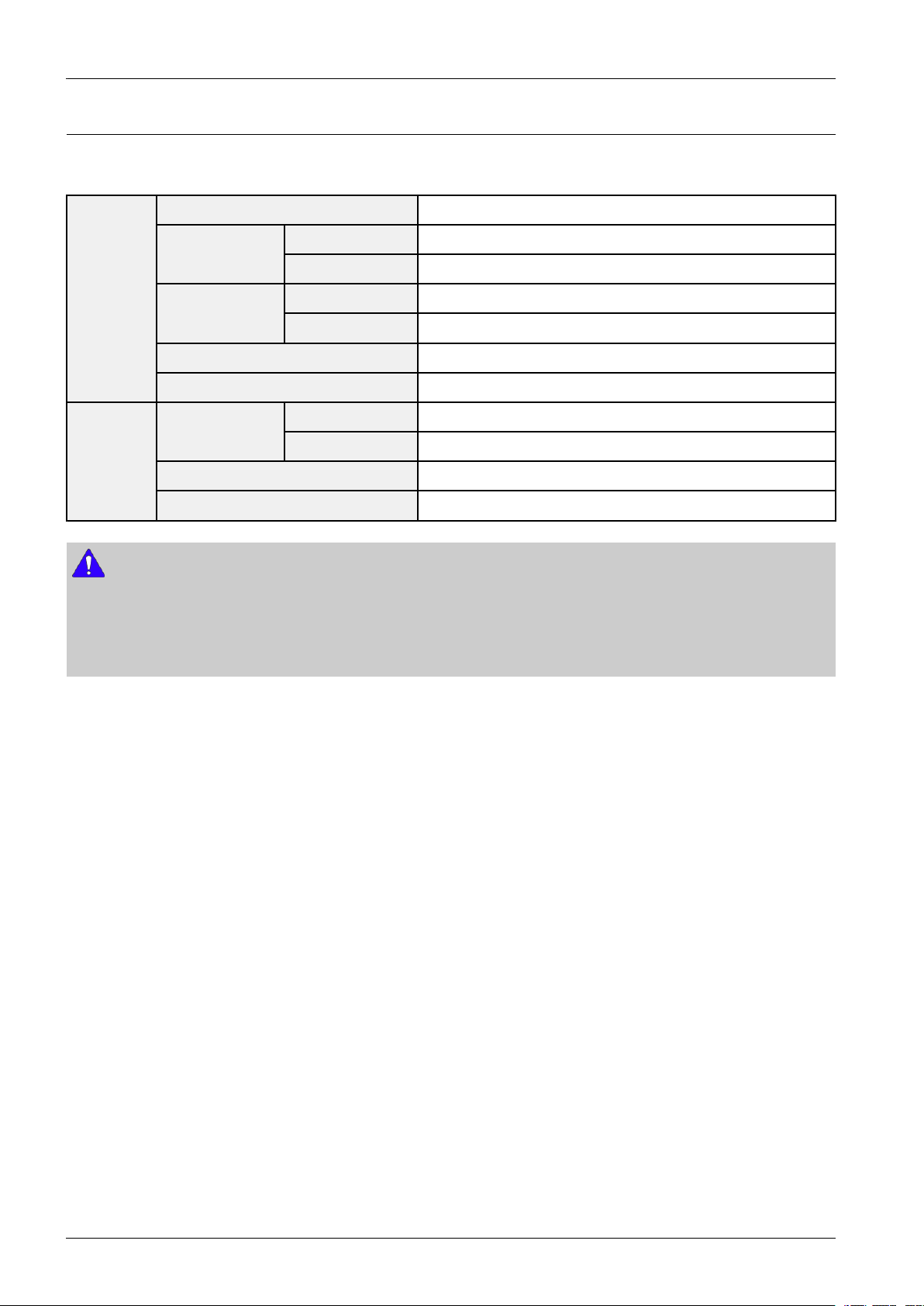
2.2.Specications
■BasicSpecication
USB5V/0.5A
Weight
General
Amplier
NOTE
•S/Nratio,distortion,separationandusablesensitivityarebasedonmeasurementusingAES(AudioEngineeringSociety)
guidelines.
•SamsungElectronicsCo.,Ltdreservestherighttochangethespecicationswithoutnotice.
•Weightanddimensionsareapproximate.
Dimensions
(WxHxD)
Operatingtemperaturerange+5°Cto+35°C
Operatinghumidityrange10%to75%
Ratedoutput
power
S/Nratio(analoginput)60dB
Separation(1kHz)50dB
Mainunit1.75kg
Subwoofer3.0kg
Mainunit943x49x59.9mm
Subwoofer152x300x284mm
Mainunit30W/CH,8OHM,THD=10%,1kHz
Subwoofer60W,3OHM,THD=10%,100Hz
2-2Copyright©1995-2013SAMSUNG.Allrightsreserved.
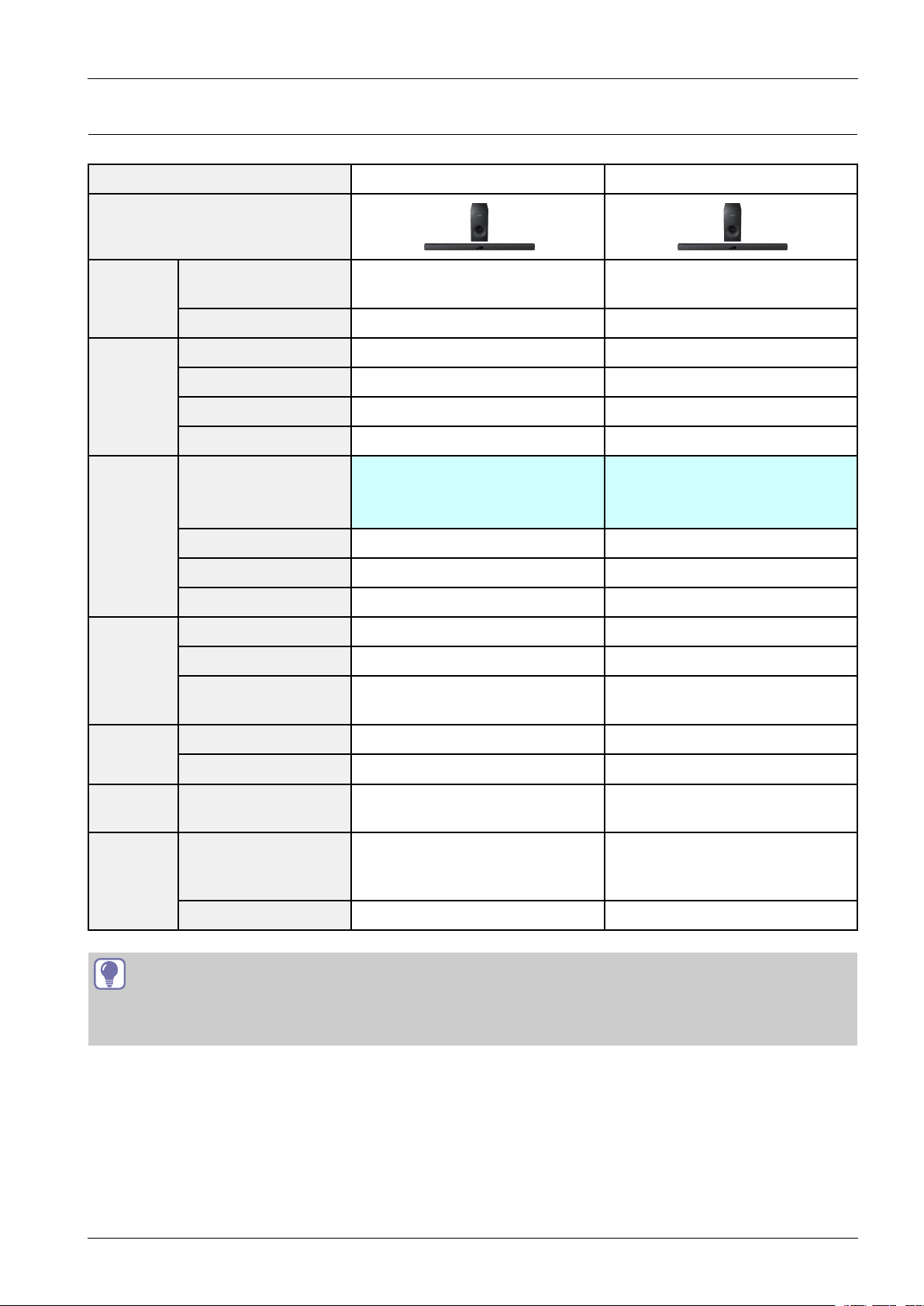
2.3.SpecicationsAnalysis
ModelNameHW-H355HW-F355
Photo
2.ProductSpecication
Output
Power
Extra
Features
DSP
Decoding
RMS(10%THD),
REF:1ch
OutputPower(ch)30Wx2+60W30Wx2+60W
WirelessReady--
SoundConnectOO
USBHOSTOO
BluetoothOO
VirtualSurround
3DSOUND3DSoundPlus3DSoundPlus
ASC--
SmartV olumeSmartVolumeIISmartVolumeII
DolbyDigital/PlusDolbyDigital2.0DolbyDigital2.0
DolbyT rueHDN/AN/A Audio
DTS/DTS-HD
(HR/MA)
Music/Voice/Sports/Cinema
120W120W
4mode
Music/News/Cinema/Drama/
/Standard(Off)
DTSDTS
Sports/Game/Standard(Off)
6mode
O:FeatureIncluded
X:NotIncluded
Audio
In/Out
Optical
Jack
Speaker
TIP
MiniJackAudioInAUX1(3.5φ)AUX1(3.5φ)
RCAInput--
In(DigitalIn)O(1)O(1)
InternalT ype
Type(Sat/T allboy)
Active(Powered)S/WWiredPassiveWiredPassive
(MainFrameBuilt-InType)
1way1spk
InternalT ype
(MainFrameBuilt-InType)
1way1spk
Copyright©1995-2013SAMSUNG.Allrightsreserved.2-3
2.ProductSpecication
POWER
TV POWER
AH59-02548A
TV VOL TV CH AUDIO SYNC
AUX USB TV SOURCE
TV PRE-CH
TV EXIT
SMART VOLUMESOUND EFFECT
S/W
LEVEL
S/W
LEVEL
VOL
VOL
3D SOUND
PLUS
DRC
TV INFOTV MUTE
AUTO POWER
DIMMERREPEAT
OPTICAL
MUTE
(S cre w:2EA)
(H
olde r-s c re w:2E A)
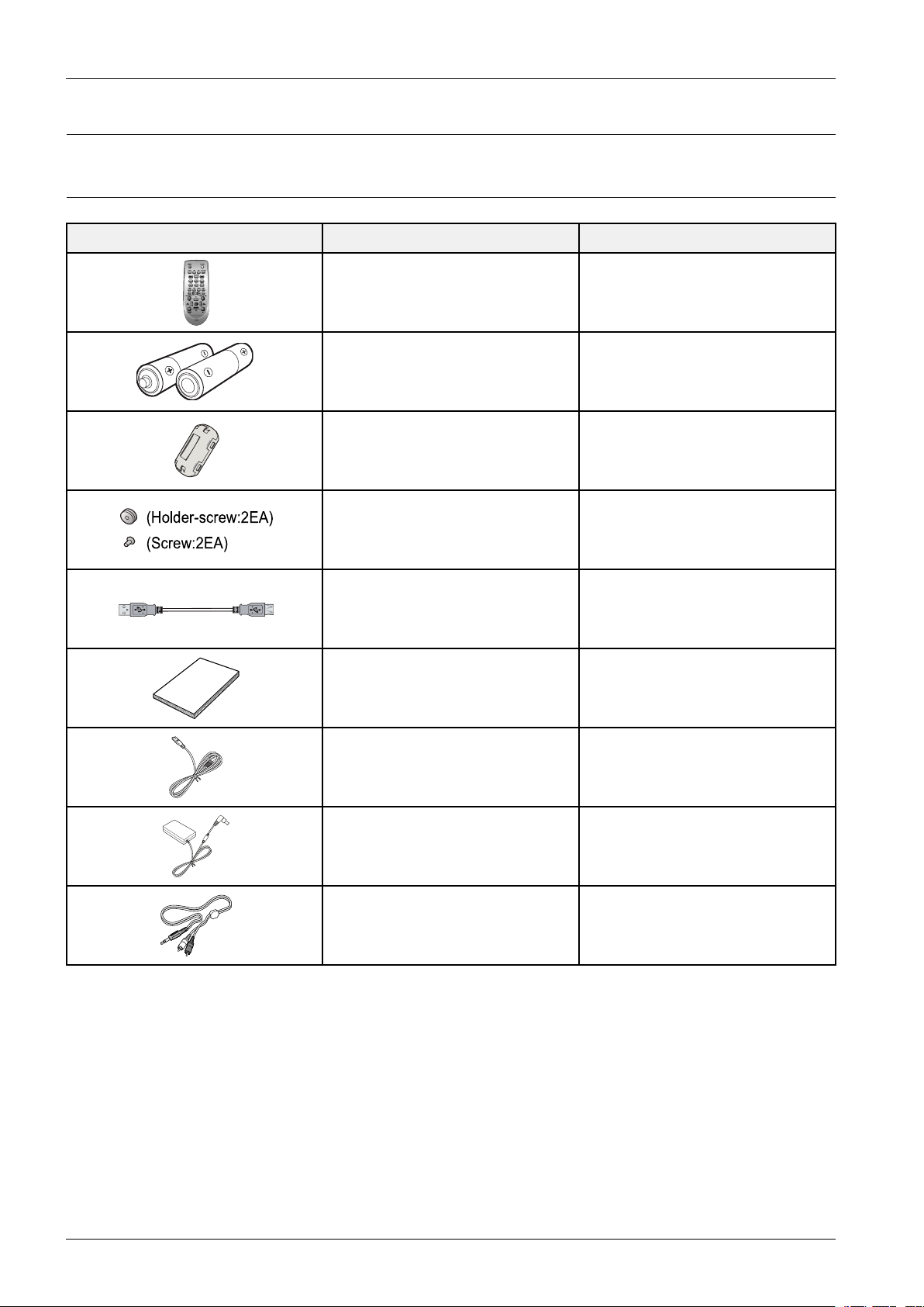
2.4.Accessories
2.4.1.SuppliedAccessories
AccessoriesItemItemcode
RemoteControlAH59-02612A
Batteries(AAAsize)4301-000116
FerriteCore3301-001068
Screw
USBCableAH39-01270A
UserManualAH68-02676A
PowerCord3903-000539
AdapterBN44-00722A
AudioCableAH39-01077A
AH61-03342A
6001-001961
2-4Copyright©1995-2013SAMSUNG.Allrightsreserved.
3.Disassembly&Reassembly
3.Disassembly&Reassembly
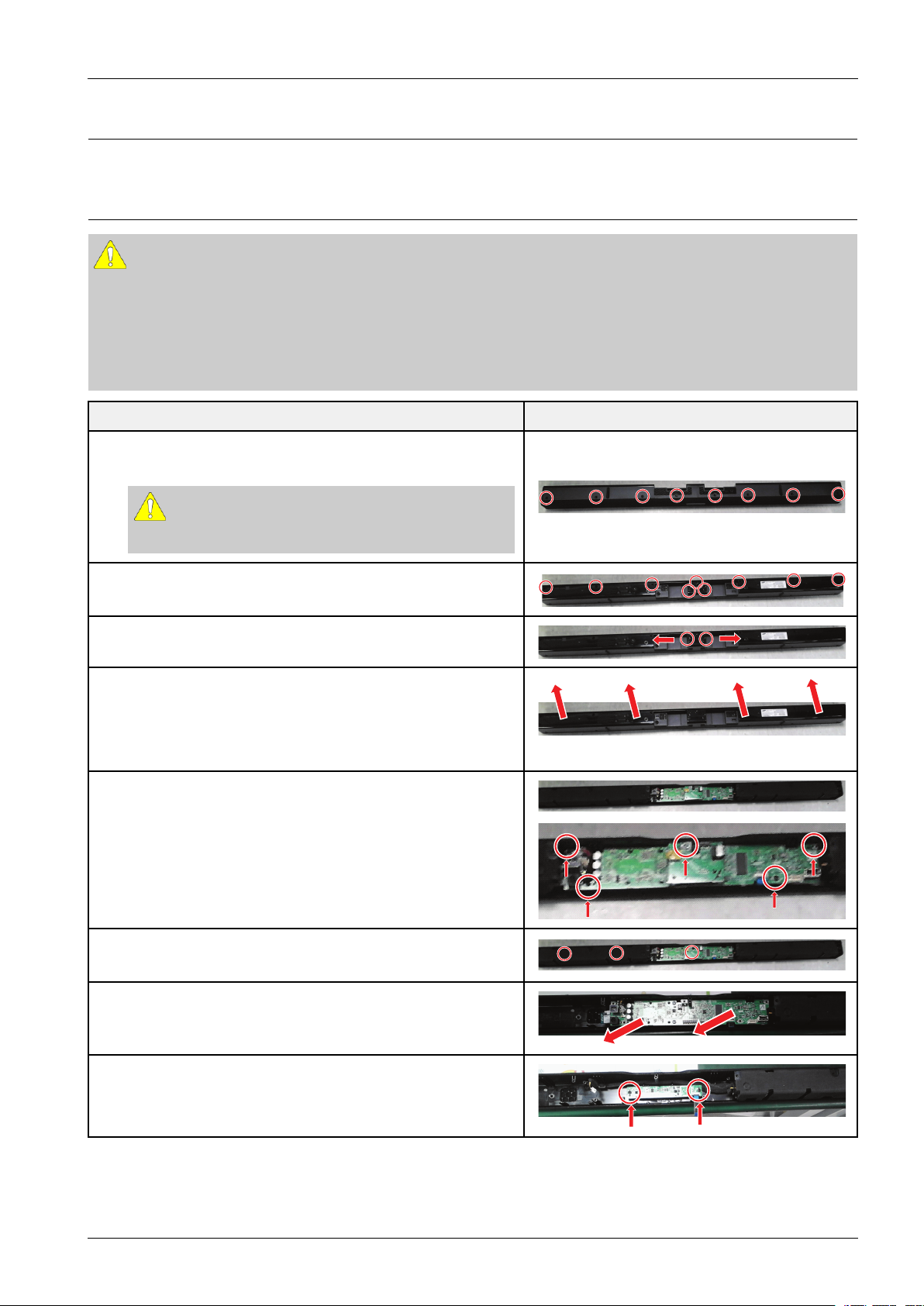
3.1.OverallDisassemblyandReassembly
CAUTION
•Becarefultofollowthedisassemblysequencedescribedinthemanual.Otherwise,theproductmaybedamaged.
•BesuretocarefullyreadandunderstandthesafetyinstructionsbeforeperforminganyworkastheICchipson
thePCBarevulnerabletostaticelectricity.
•Inordertoassemblereversetheorderofdisassembly.
DescriptionDescriptionPhoto
1.Loosen8screwsattheRearCover.
:M3X10B
CAUTION
Becarefulnottomakeanyscratchesasyouremovethem.
2.Loosen9screwsattheRearCover.
:M3X10B
3.Open2JackCoversattheRearCover.
4.PulltheRearCoverinthedirectionofthearrows.
5.Loosen5screwsontheboards.
:M3X10B,M3X5S
UnplugAllConnectorsontheMainPCB.
6.RemovetheLeftSpeaker.
RemovetheJackPCB.
7.RemovetheMainASSY.
8.Loosen2screwsattheVFDPCB.
:M3X10B
Copyright©1995-2013SAMSUNG.Allrightsreserved.3-1
3.Disassembly&Reassembly
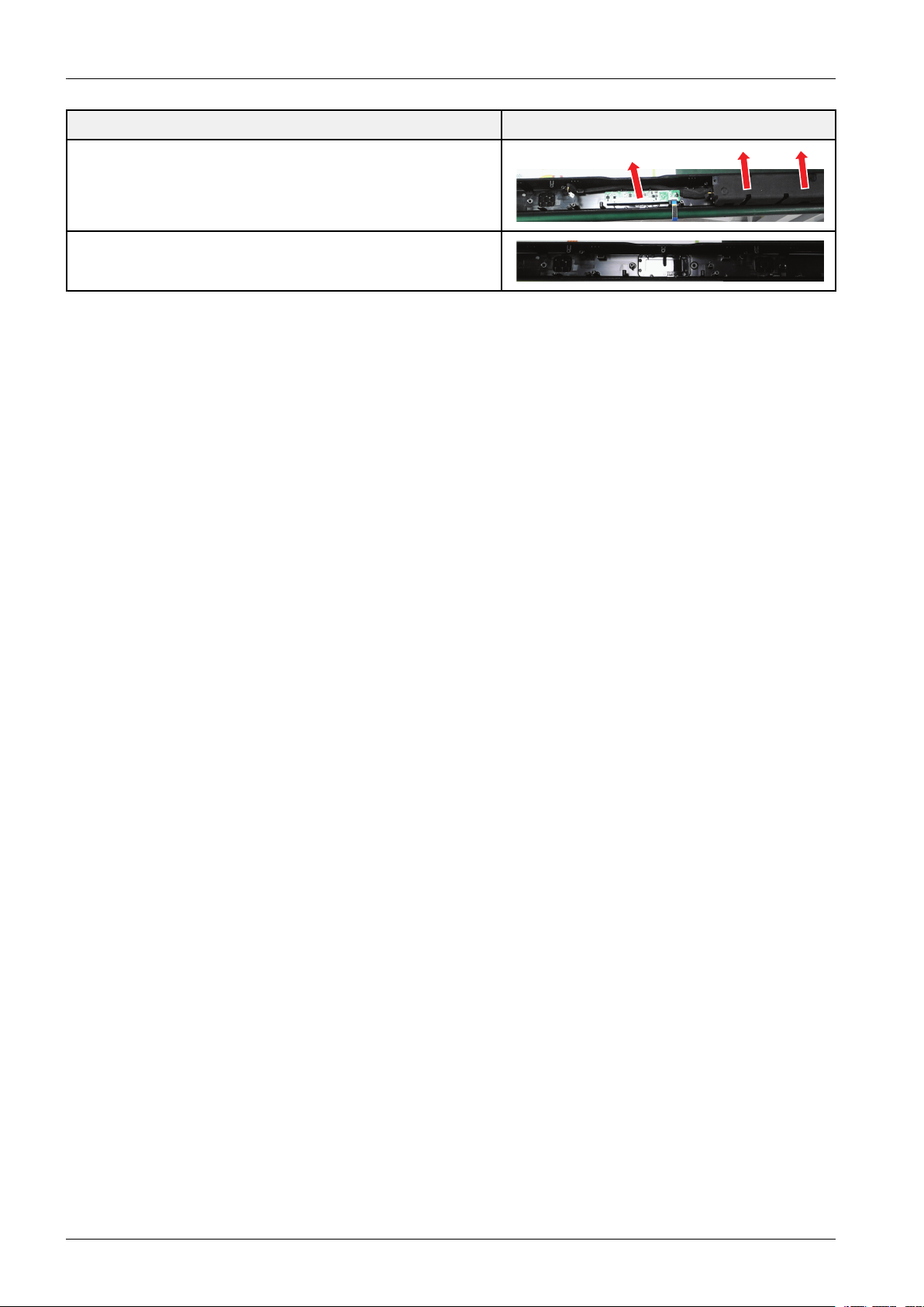
9.RemovetheVFDPCB.
PulltheRightSpeaker.
10.Finish.
DescriptionDescriptionPhoto
3-2Copyright©1995-2013SAMSUNG.Allrightsreserved.

4.Troubleshooting
4.1.CheckpointsbyErrorMode
V oltage/DIV1V/div
TIME/DIV500ms/div
4.Troubleshooting
OscilloscopeSettingV alues
Copyright©1995-2013SAMSUNG.Allrightsreserved.4-1
4.Troubleshooting
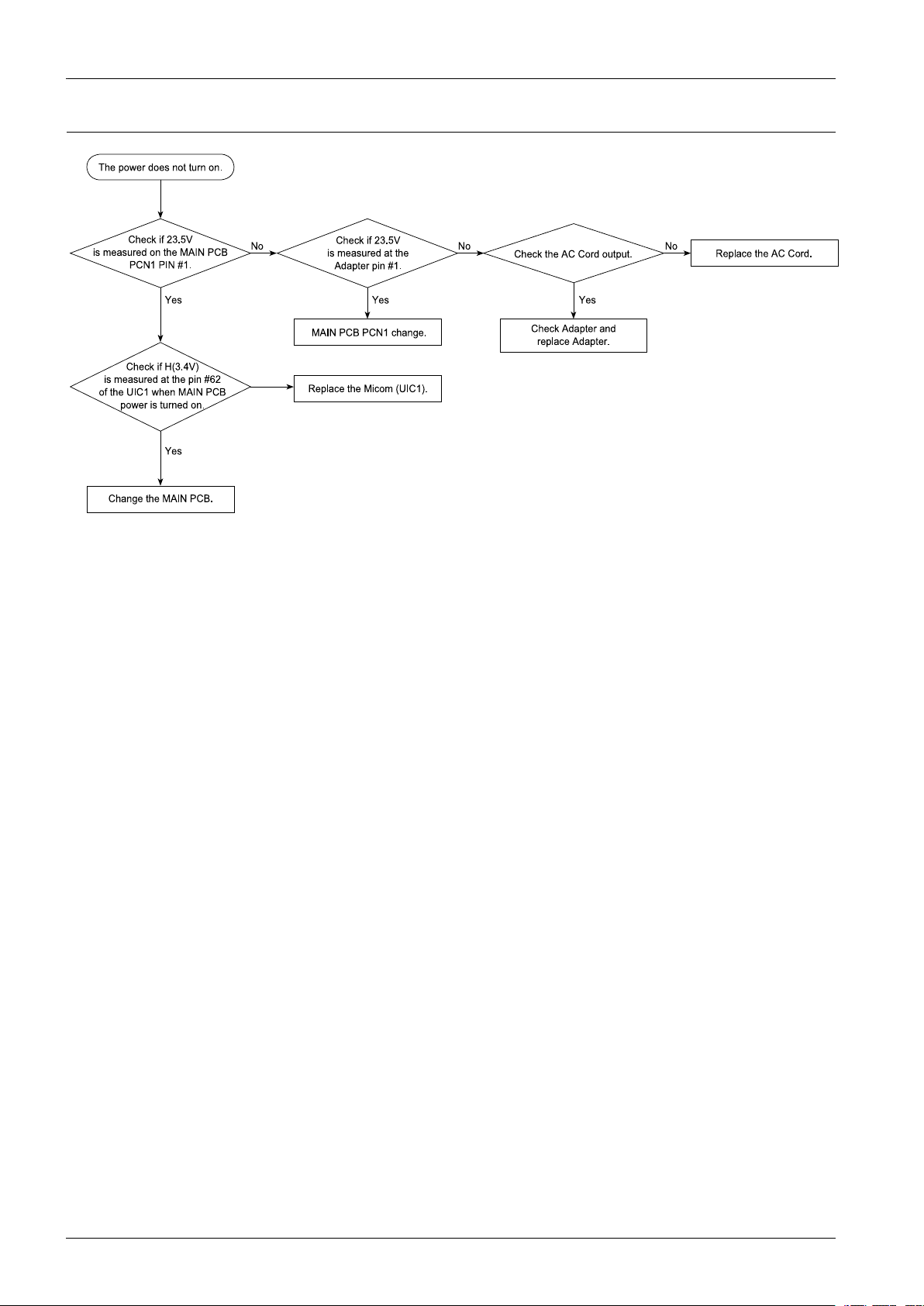
Check if 23. 5V
is m e a sure d on the MAIN PC B
PCN1 P IN #1.
Check if 23. 5V
is m e a sure d at the
Adapte r pin #1 .
Check th e AC Cord output.
Yes
MAIN PC B P CN1 cha nge .
No No No
Yes
The powe r doe s n ot tu rn on.
Change the MAIN PC B.
Yes
Check if H(3.4 V)
is m e a sure d at the pin #6 2
of the UIC1 wh en MAIN PCB
power is tu rne d on .
Re place the AC C ord .
Re place the Micom (UIC1).
Check Ada pter a nd
replace Ada pter.
Yes
4.1.1.NoPower
4-2Copyright©1995-2013SAMSUNG.Allrightsreserved.

4.1.2.NoSoundOutput(Digital)
Ye s
Chan ge t he
MAIN
P CB.
Cha nge the
MAIN
P CB.
No
No output
Ye s
Che ck S P DIF Outp ut.
Che ck DS P.
Change speaker connect or.
Check if 3.3 V
power is measured at
pin 1 of OPJ ACK1 o n the
MAIN P CB.
Check if 3.3 V
power is measured at
pin 95 of IC3002 o n the
MAIN P CB.
(1)
Che ck if sign a l is
me a s ure d a t pin No. 69,70,71,74
of IC3002 on the
MAIN P C B.
(2)
Check if signa l is
measured a t pin No. 32,35
of IC4002 on the
MAIN P CB.
(3)
Check the MAIN P CB
ACN1,ACN2 speaker
output signa l.
* Re fer to wave p a tte rn
image of Fig. 4-2 .
Cha nge Sp e a ke r.
Ye s
No
No
No
No
No
Cha nge the
MAIN
P CB.
Cha nge the
MAIN
P CB.
Cha nge the J ACK PCB.
Spea ke r ou tput che ck.
* Re fer to wave p a tte rn
image of Fig. 4-1 .
* Re fer to wave p a tte rn
image of Fig. 4-3 .
Ye s
Ye s
A
4.Troubleshooting
Copyright©1995-2013SAMSUNG.Allrightsreserved.4-3

4.Troubleshooting
IC 3 002
* 5.3. MAIN PCB Bottom
PWM_S W-
BA1_ST
BA0_ST
RAS_PLL2
CAS_PLL3
DQM_PLL0
DWE_PLL1
SPI_ CS3
CST_MAK
D_MO_CI
MST_C AK
OTW
VRP_ CTR
4.7KOHM
R500 5
4.7KOHM
R38
4.7KOHM
R39
4.7KOHM
R500 6
4.7KOHM
R500 7
DATA13
DATA14
DATA15
DATA9
DATA10
DATA11
DATA12
100 OHM
+-250 PPM/C
R137
1
3
5
7
2
4
6
8
100 OHM
+-250 PPM/C
R136
1
3
5
7
2
4
6
8
DATA0
DATA8
DATA2
DATA1
DATA6
DATA7
DATA5
DATA4
DATA3
100 OHM
+-250 PPM/C
R135
1
3
5
7
2
4
6
8
+-250 PPM/C
100 OHM
R134
1
3
5
7
2
4
6
8
L_UDQM
/DR_WE
/CAS
/RAS
BA0
/DR_CS
100 OHM
1/16 W
R37
56O HM
1/16 W
R36 100 OHM
1/16 W
R301 4
100 OHM
1/16 W
R35
100 OHM
1/16 WR34
100 OHM
1/16 W
R33
100 OHM
1/16 W
R32
BA1
ADD2
ADD1
ADD10
ADD0
100 OHM
+-250 PPM/C
R133
1
3
5
7
2
4
6
8
ADD11
ADD8
ADD9
ADD3
ADD6
ADD5
ADD7
100 OHM
+-250 PPM/C
R132
1
3
5
7
2
4
6
8
100 OHM
+-250 PPM/C
3
5
7
4
6
8
100OHM 1/16W
R3025
100OHM 1/16W
R3024
100OHM 1/16 W
R3022
100OHM
1/16W
R3023
10KOH
M
1/16W
R30 97
ES86 80 DSC
IC3002
1
2
3
4
5
6
7
8
9
10
11
12
13
14
15
16
17
18
19
20
21
22
23
24
25
26
27
28
29
30
31
32
33343536373839404142434445464748495051525354555657585960616263
64
65
66
67
68
69
70
71
72
73
74
75
76
77
78
79
80
81
82
83
84
85
86
87
88
89
90
91
92
93
94
95
96
979899
100
101
102
103
104
105
106
107
108
109
110
111
112
113
114
115
116
117
118
119
120
121
122
123
124
125
126
127
128
MGND1
100O HM
1/16W
R42
100O HM
1/16W
R43
DGND
100O HM
1/16W
R309 9
TP_ REAR
100O HM
1/16W
R310 1
100O HM
1/16W
R46
4.7KOHM
R49
DGND
10KOHM 1/16W
R31 02
DGND
1/16W
47KOHM
R31 14
47KOHM
1/16W
R31 15
392 OHM
1/10 W
R45
100NFC56
100NFC57
56KOHM 1/16W
R400 3
56KOHM
1/16W
R400 4
AVD3.3VS
AGND
VC3.3V
2.2KO HM
1/16 W
R30 80
VC3.3V
1
2
3
6
7
8
100 NF 16V
C59
10KOHM
R30 84
VC3.3V
16V100 NF
C30 15
4.7KOHM
R50 04
100 OHM
R31 09
100 OHM
R31 13
100 OHM
R31 08
100 OHM
R31 12
100 OHM
R31 11
AGND
AUD3.3V
100 NF
16V
C30 13
100 OHM
R31 10
100 OHM
R32 10
100 OHM
R32 11
AGND
D_CO _MI
EP ROM_WP
PWM_L+
PWM_R -
PWM_R +
PWM_L-
PWM_S W+
DGND
2.2KOHM
R52
2.2KOHM
R53
100 NF 16V
C301 2
10KOHM
R30 87
10KOHM
R30 85
150O HM
1/16W
R50
100 NF
16V
C30 11
VD3.3VPLL
27P F
50V
C58
100KOHM
1/16W
R51
27MHZ
X3001
1
23
4
SP DIF_IN1
D+1.3 5V
DGND
27P F
50V
C60
DCS0_B
DMA[1]
DWE_B
DAC_O4L
DAC_O4R
DAC_O5L
DAC_O5R
LINE_IN_R2
LINE_IN_L1
LINE_IN_R1
VDDAADC
VS33AADCVS33VDAC
PAD_REF
PAD_COMP
PAD_RS ET
VDAC
VD33VDAC
USB_VCCA
USB_DM
USB_D
P
USB_AGND
VDD
VD33
DMA[4]
DMA[5]
SYSCLK
DMA[2]
VDD
DMA[3]
DMA[11
]
DMA[9]
DMA[8]
DMA[7]
DMA[6]
DB[9]
DB[10]
DB[11]
VD33
DB[12]
DB[13]
DB[14]
DB[15]
AUX[7]
AUX[6]
AUX[5]
AUX[4]
AUX[3]
RESE T_B
AUX[2]
AUX[1]
SR[12]
SR[13]
SP[21 ]
VD33
VSS/VS3 3
SR[15]
SR[32]
SR[06]
DAC_O1L
DAC_O1R
DAC_O2L
VD33ADAC
VS33ADAC
DAC_O2R
DAC_O3L
DAC_O3R
OP[2]
OP[3]
OP[4]
OP[5]
OP[6]
OP[7]
VDD
SR[10]
SR[11]
DMA[0]
DMA[10]
DRAS2_B
DRAS1_B
DCS1_B
DRAS0_B
DCAS_B
DSCK
VDD
DQM
VD33
DB[7]
DB[6]
DB[5]
DB[4]
DB[3]
DB[2]
DB[1]
DB[0]
VDD
DB[8]
AUX[0]
DAC_O6L
VD33ADAC
VS33ADAC
DAC_O6R
VSS/VS3 3
SR[07]
SR[05]
VSS/VS3 3
MCLK
VDD
VID_XO
VID_XI
VD33
SPDIF_ IN
VD33PLL
VS33P LL
VD33AADC
LINE_IN_L3
LINE_IN_R3
LINE_IN_L2
SPI_C S2
SPI_C S3
SPI_C LK
VD33
SPI_DI
SPI_DO
VDD
SPDIF_ OUT
OP[0]
OP[1]
W
P
VCC
SCLA2
A1
A0
Q
3
Q2 Q1
Q0
4.7KOHM
4.7KOHM
4.7KOHM
4.7KOHM
4.7KOHM
100 OHM
+-250 PPM/C
100 OHM
+-250 PPM/C
100 OHM
+-250 PPM/C
+-250 PPM/C
100 OHM
100 OHM
1/16 W
56O HM
1/16 W
100 OHM
1/16 W
100 OHM
1/16 W
100 OHM
1/16 W
100 OHM
1/16 W
100 OHM
1/16 W
100 OHM
+-250 PPM/C
100 OHM
+-250 PPM/C
100 OHM
+-250 PPM/C
100OH M 1 /16W
100OH M 1 /16W
100OH M 1/16W
100OHM
1/16W
10KOH
M
1/16W
ES86 80 DSC
100O HM
1/16W
100O HM
1/16W
DGND
100O HM
1/16W
100O HM
1/16W
100O HM
1/16W
4.7KOHM
DGND
10KOHM 1/16W
DGND
1/16W
47KOHM
47KOHM
1/16W
392 OHM
1/10 W
100NF
100NF
56KOHM 1/16W
56KOHM
1/16W
AVD3.3VS
AGND
VC3.3V
2.2KO HM
1/16 W
VC3.3V
100 NF 16V
10KOHM
VC3.3V
16V100 NF
4.7KOHM
100 OHM
100 OHM
100 OHM
100 OHM
100 OHM
AGND
AUD3.3V
100 NF
16V
100 OHM
100 OHM
100 OHM
AGND
DGND
2.2KOHM
2.2KOHM
100 NF 16V
10KOHM
10KOHM
150O HM
1/16W
100 NF
16V
VD3.3VPLL
27P F
50V
100KOHM
1/16W
27MHZ
D+1.3 5V
DGND
27P F
50V
R500 5
R38
R39
R500 6
R500 7
R137
R136
R135
R134
R37
R36
R3014
R35
R34
R33
R32
R133
R132
R3025
R3024
R3022
R3023
R30 97
IC3002
R42
R43
R309 9
TP_ REAR
R310 1
R46
R49
R31 02
R31 14
R31 15
R45
C56
C57
R400 3
R400 4
R30 80
C59
R30 84
C30 15
R50 04
R31 09
R31 13
R31 08
R31 12
R31 11
C30 13
R31 10
R32 10
R32 11
R52
R53
C301 2
R30 87
R30 85
R50
C30 11
C58
R51
X3001
C60
PWM_S W-
BA1_ST
BA0_ST
RAS_PLL2
CAS_PLL3
DQM_PLL0
DWE_PLL1
SPI_ CS3
CST_MAK
D_MO_CI
MST_C AK
OTW
VRP_ CTR
DATA13
DATA14
DATA15
DATA9
DATA10
DATA11
DATA12
DATA0
DATA8
DATA2
DATA1
DATA6
DATA7
DATA5
DATA4
DATA3
L_UDQM
/DR_WE
/CAS
/RAS
BA0
/DR_CS
BA1
ADD2
ADD1
ADD10
ADD0
ADD11
ADD8
ADD9
ADD3
ADD6
ADD5
ADD7
D_CO _MI
EP ROM_WP
PWM_L+
PWM_R -
PWM_R +
PWM_L-
PWM_S W+
SP DIF_IN1
1
3
5
7
2
4
6
8
1
3
5
7
2
4
6
8
1
3
5
7
2
4
6
8
1
3
5
7
2
4
6
8
1
3
5
7
2
4
6
8
1
3
5
7
2
4
6
8
3
5
7
4
6
8
1
2
3
4
5
6
7
8
9
10
11
12
13
14
15
16
17
18
19
20
21
22
23
24
25
26
27
28
29
30
31
32
33343536373839404142434445464748495051525354555657585960616263
64
65
66
67
68
69
70
71
72
73
74
75
76
77
78
79
80
81
82
83
84
85
86
87
88
89
90
91
92
93
94
95
96
979899
100
101
102
103
104
105
106
107
108
109
110
111
112
113
114
115
116
117
118
119
120
121
122
123
124
125
126
127
128
MGND1
1
2
3
6
7
8
1
2 3
4
DCS0_B
DMA[1]
DWE_B
DAC_O4L
DAC_O4R
DAC_O5L
DAC_O5R
LINE_IN_R2
LINE_IN_L1
LINE_IN_R1
VDDAADC
VS33AADC
VS33VDAC
PAD_REF
PAD_COMP
PAD_RS ET
VDAC
VD33VDAC
USB_VCCA
USB_DM
USB_D
P
USB_AGND
VDD
VD33
DMA[4]
DMA[5]
SYSCLK
DMA[2]
VDD
DMA[3]
DMA[11]
DMA[9]
DMA[8]
DMA[7]
DMA[6]
DB[9]
DB[10]
DB[11]
VD33
DB[12]
DB[13]
DB[14]
DB[15]
AUX[7]
AUX[6]
AUX[5]
AUX[4]
AUX[3]
RESE T_B
AUX[2]
AUX[1]
SR[12]
SR[13]
SP[21 ]
VD33
VSS/VS3 3
SR[15]
SR[32]
SR[06]
DAC_O1L
DAC_O1R
DAC_O2L
VD33ADAC
VS33ADAC
DAC_O2R
DAC_O3L
DAC_O3R
OP[2]
OP[3]
OP[4]
OP[5]
OP[6]
OP[7]
VDD
SR[10]
SR[11]
DMA[0]
DMA[10]
DRAS2_B
DRAS1_B
DCS1_B
DRAS0_B
DCAS_B
DSCK
VDD
DQM
VD33
DB[7]
DB[6]
DB[5]
DB[4]
DB[3]
DB[2]
DB[1]
DB[0]
VDD
DB[8]
AUX[0]
DAC_O6L
VD33ADAC
VS33ADAC
DAC_O6R
VSS/VS3 3
SR[07]
SR[05]
VSS/VS3 3
MCLK
VDD
VID_XO
VID_XI
VD33
SPDIF_ IN
VD33PLL
VS33P LL
VD33AADC
LINE_IN_L3
LINE_IN_R3
LINE_IN_L2
SPI_C S2
SPI_C S3
SPI_C LK
VD33
SPI_DI
SPI_DO
VDDSPDIF_ OUT
OP[0]
OP[1]
WP
VCC
SCLA2
A1
A0
Q3
Q2 Q1
Q0
* 6.4. MAIN-3
<Fig. 4-1>
(1)
(1)
(1)
4-4Copyright©1995-2013SAMSUNG.Allrightsreserved.

IC4002
* 5.3. MAIN PCB Bottom
FL/FR
DGND
100OHM
AR7
100OHM 1/10W
AR6
100OHM 1/10W
AR5
1UF 16V
C113
100NF 16V
C112
1UF 16V
AC3
100PF
50V
C111
30KOHM 1/10W
R8 2
100OHM 1/10W
R8 1
47KOH M
1/10 W
R8 3
TAS5 614 LADDV
IC400 2
1
2
3
4
5
6
7
8
9
10
11
12
13
14
15
16
17
18
19
20
21
22 23
24
25
26
27
28
29
30
31
32
33
34
35
36
37
38
39
40
41
42
43
44
33 NF 50V
C1 24
33 NF 50V
C1 48
DGND
10 UF
25 V
AC9
10 UF
25 V
AC5
10 UF
25 V
AC11
10 UF
25 V
AC10
10 UF
25 V
AC26
DGND
10 UF
25 V
AC15
10 UF
25 V
AC25
10 UF
25 V
AC14
BST_A
BST_B
GND
GND
OUT_A
OUT_A
PVDD_AB
PVDD_AB
PVDD_AB
OUT_B
GND
GND
OUT_C
PVDD_C D
PVDD_C D
PVDD_C D
OUT_D
OUT_D
GND
GND
BST_C
BST_D
GVDD_CD
GND
M3
M2
M1
/CLIP
/OTW
/FAULT
INPUT_D
INPUT_C
AVDD
GND
GND
GVDD_AB
INPUT_A
INPUT_B
/RESE T
OC_ADJ
VDD
C_S TART
DVDD
GND
FR
DGND
100OHM
100OHM 1/10W
100OHM 1/10W
1UF 16V
100NF 16V
1UF 16V
100PF
50V
30KOHM 1/10W
100OHM 1/10W
47KOH M
1/10 W
TAS5 614 LADDV
33 NF 50 V
33 NF 50 V
DGND
10 UF
25 V
10 UF
25 V
10 UF
25 V
10 UF
25 V
10 UF
25 V
DGND
10 UF
25 V
10 UF
25 V
10 UF
25 V
AR7
AR6
AR5
C113
C112
AC3
C111
R8 2
R8 1
R8 3
IC400 2
C1 24
C1 48
AC9
AC5
AC1
1
AC10
AC26
AC1
5
AC25
AC1
4
1
2
3
4
5
6
7
8
9
10
11
12
13
14
15
16
17
18
19
20
21
22 23
24
25
26
27
28
29
30
31
32
33
34
35
36
37
38
39
40
41
42
43
44
BST_A
BST_B
GND
GND
OUT_A
OUT_A
PVDD_AB
PVDD_AB
PVDD_AB
OUT_B
GND
GND
OUT_C
PVDD_C D
PVDD_C D
PVDD_C D
OUT_D
OUT_D
GND
GND
BST_C
BST_D
GVDD_CD
GND
M3
M2
M1
/CLIP
/OTW
/FAULT
INPUT_D
INPUT_C
AVDD
GND
GND
GVDD_AB
INPUT_A
INPUT_B
/RESE T
OC_ADJ
VDD
C_S TART
DVDD
GND
* 6.6. MAIN-5
<Fig. 4-2>
(2)
(2)
(2)
4.Troubleshooting
Copyright©1995-2013SAMSUNG.Allrightsreserved.4-5

4.Troubleshooting
AC N3
AC N1
AC N2
* 5.2. MAIN PCB To p
SPK _F R-
SPK _F L+
10 0NF
50 V
AC39
DGND
10 NF
50 V
C12 8
3.3OHM
1/10 W
R10 3
1/10 W
3.3OHM
R10 2
DGND
100NF
50V
AC38
10NF
50V
C22
10NF
50V
C19
2.2NF 50 V
AC44
2.2NF 50 V
AC43
10 0NF 50 V
AC46
10 0NF 50 V
AC48
3.3NF 50 V
AC55
3.3NF 50 V
AC56
L(-)
L(+)
R(-)
L1(-)
L1(+)
SMW20 0-H0 3G
ACN1
1
2
3
MGND1
MGND2
R1 (-)
SMW20 0-H0 2G
ACN2
1
2
MGND1
MGND2
2.2NF 50V
AC42
2.2NF 50V
AC41
100NF 50V
AC45
100NF 50V
AC47
R(+)
3.3NF
50V
AC53
3.3NF 50V
AC54
R1 (+)
DGND
DGND
SP1 _GND
SP_ GND
10 0NF
50 V
DGND
10 NF
50 V
3.3OHM
1/10 W 1/10 W
3.3OHM
DGND
100NF
50V
10NF
50V
10NF
50V
2.2NF 50 V
2.2NF 50 V
10 0NF 50 V
10 0NF 50 V
3.3NF 50 V
3.3NF 50 V
SMW20 0-H0 3G
SMW20 0-H0 2G
2.2NF 50V
2.2NF 50V
100NF 50V
100NF 50V
3.3NF
50V
3.3NF 50V
DGND
DGND
AC39
C12 8 R103 R10 2
AC38
C22 C19
AC44
AC43
AC46
AC48
AC55
AC56
L(-)
L(+)
R(-)
L1(-)
L1(+)
ACN1
R1 (-)
ACN2
AC42 AC41
AC45
AC47
R(+)
AC53
AC54
R1 (+)
SP1 _GND
SP_ GND
SPK _F R-
SPK _F L+
1
2
3
MGND1
MGND2
1
2
MGND1
MGND2
* 6.6. MAIN-5
<Fig. 4-3>
(3)
(3)
(3)
(3)
(3)
4-6Copyright©1995-2013SAMSUNG.Allrightsreserved.

4.1.3.NoSoundOutput(Analog)
Che ck if 3.3V
powe r is me a s ure d a t pin 95 of
CN3002 on the
MAIN
PCB.
(1)
Che ck if s igna l is
me a sure d at pin no. 2, 4 of AUX1
on the J ACK PCB.
(2)
Check if signal is
measured at pin No. 69,70,71,74
of IC3002 on the
MAIN P CB.
Ye s
No
No output
Check ANALOG OUTPU T.
Ch e ck DS P.
Ye s
No
No
* Re fer to wave pa tte rn
image of Fig. 4-5.
A
Go to “No output(Digital) - A”
* Re fer to wave pa tte rn
image of Fig. 4-4.
Cha nge
the
MAIN P CB.
Cha nge
the
J ACK PCB.
Cha nge
the
MAIN P CB.
4.Troubleshooting
Copyright©1995-2013SAMSUNG.Allrightsreserved.4-7

4.Troubleshooting
* 5.6. J ACK PCB To p
AUX_L_H
AUX_R_H
HDGND
3
7
6
5
4
2
1
AUX1
GCC02-0139R
VT1
MLVS-0 60 3-E 08
11
VT2
11
MLVS-0 60 3-E 08
AAC4
16 V
10 0NF
1/1 6W
47 0O HM
AAR1
AAC5
16 V
10 0NF
AAC6
50 V
33 0P F
AAC8
50 V
33 0P F
AAR2
1/1 6W
33 0O HM
AAR3
1/1 6W
33 0O HM
AAR4
1/1 6W
220 KOHM
AAR5
1/1 6W
220 KOHM
AAC9
50 V
33 0P F
AAC1 0
50 V
33 0P F
AUX_S ENS_ H
DGND
GCC02-0139R
MLVS-0 60 3-E 08
11
11
MLVS-0 60 3-E 08
16 V
10 0NF
1/1 6W
47 0O HM
16 V
10 0NF
50 V
33 0P F
50 V
33 0P F
1/1 6W
33 0O HM
1/1 6W
33 0O HM
1/1 6W
220 KOHM
1/1 6W
220 KOHM
50 V
33 0P F
50 V
33 0P F
AUX1
VT1
VT2
AAC4
AAR1
AAC5
AAC6
AAC8
AAR2
AAR3
AAR4
AAR5
AAC9
AAC1 0
AUX_L_H
AUX_R_H
AUX_S ENS_ H
3
7
6
5
4
2
1
* 6.8. J ACK
<Fig. 4-4>
(1)
(1)
(1)
(1)
(1)
4-8Copyright©1995-2013SAMSUNG.Allrightsreserved.

IC3002
* 5.3. MAIN PCB Bottom
PWM_S W-
BA1_ST
BA0_ST
RAS_PLL2
CAS_PLL3
DQM_PLL0
DWE_PLL1
SP I_CS3
CS T_MAK
D_MO_C I
MST_C AK
OTW
VRP_ CTR
4.7KOHM
R500 5
4.7KOH
M
R38
4.7KOHM
R39
4.7KOHM
R500 6
4.7KOHM
R500 7
DATA13
DATA14
DATA15
DATA9
DATA10
DATA11
DATA12
100 OHM
+-250 PP M/C
R137
1
3
5
7
2
4
6
8
100 OHM
+-250 PP M/C
R136
1
3
5
7
2
4
6
8
DATA0
DATA8
DATA2
DATA1
DATA6
DATA7
DATA5
DATA4
DATA3
100 OHM
+-250 PP M/C
R135
1
3
5
7
2
4
6
8
+-250 PP M/C
100 OHM
R134
1
3
5
7
2
4
6
8
L_UDQM
/DR_WE
/CAS
/RAS
BA0
/DR_C S
100 OHM
1/16 W
R37
56O HM
1/16 W
R36 100 OHM
1/16 W
R30 14
100 OHM
1/16 W
R35
100 OHM
1/16 WR34
100 OHM
1/16 W
R33
100 OHM
1/16 W
R32
BA1
ADD2
ADD1
ADD10
ADD0
100 OHM
+-250 PP M/C
R133
1
3
5
7
2
4
6
8
ADD11
ADD8
ADD9
ADD3
ADD6
ADD5
ADD7
100 OHM
+-250 PP M/C
R132
1
3
5
7
2
4
6
8
100 OHM
+-250 PP M/C
3
5
7
4
6
8
100OHM 1/16W
R30 25
100OHM 1/16W
R30 24
100OHM 1/16W
R30 22
100OHM
1/16W
R30 23
10KOHM
1/16W
R30 97
ES8680DSC
IC3002
1
2
3
4
5
6
7
8
9
10
11
12
13
14
15
16
17
18
19
20
21
22
23
24
25
26
27
28
29
30
31
32
33343536373839404142434445464748495051525354555657
585960
616263
64
65
66
67
68
69
70
71
72
73
74
75
76
77
78
79
80
81
82
83
84
85
86
87
88
89
90
91
92
93
94
95
96
979899
100
101
102
103
104
105
106
107
108
109
110
111
112
113
114
115
116
117
118
119
120
121
122
123
124
125
126
127
128
MGND1
100O HM
1/16W
R42
100O HM
1/16W
R43
DGND
100O HM
1/16W
R309 9
TP_ REAR
100O HM
1/16W
R310 1
100O HM
1/16W
R46
4.7KOHM
R49
DGND
10KOHM
1/16 W
R31 02
DGND
1/16 W
47KOHM
R31 14
47KOHM
1/16 W
R31 15
392 OHM
1/10
W
R45
100NFC56
100NF
C57
56KOHM 1/16W
R400 3
56KOHM
1/16 W
R400 4
AVD3.3VS
AGND
VC3.3V
2.2 KOHM
1/16 W
R30 80
VC3.3V
1
2
3
6
7
8
100 NF 16V
C59
10KOHM
R30 84
VC3.3V
16V100N F
C30 15
4.7KOHM
R50 04
100 OHM
R31 09
100 OHM
R31 13
100 OHM
R31 08
100 OHM
R31 12
100 OHM
R31 11
AGND
AUD3.3V
100N F
16V
C30 13
100 OHM
R31 10
100 OHM
R32 10
100 OHM
R32 11
AGND
D_CO _MI
EP ROM_WP
PWM_L+
PWM_R -
PWM_R +
PWM_L-
PWM_S W+
DGND
2.2KOHM
R52
2.2KOHM
R53
100N F 16V
C301 2
10KOHM
R30 87
10KOHM
R30 85
150O HM
1/16W
R50
100N F
16V
C30 11
VD3.3VPLL
27P F
50V
C58
100KOHM
1/16W
R51
27MHZ
X3001
1
23
4
SP DIF_IN1
D+1.3 5V
DGND
27P F
50V
C60
DCS0_B
DMA[1]
DWE_B
DAC_O4L
DAC_O4R
DAC_O5L
DAC_O5R
LINE_IN_R2
LINE_IN_L1
LINE_IN_R1
VDDAADC
VS33AADC
VS33VDAC
PAD_REF
PAD_COMP
PAD_RS ET
VDAC
VD33VDAC
USB_VCCA
USB_DM
USB_DP
USB_AGND
VDD
VD33
DMA[4]
DMA[5]
SYSCLK
DMA[2]
VDD
DMA[3]
DMA[11]
DMA[9]
DMA[8]
DMA[7]
DMA[6]
DB[9]
DB[10]
DB[11]
VD33
DB[12]
DB[13]
DB[14]
DB[15]
AUX[7]
AUX[6]
AUX[5]
AUX[4]
AUX[3]
RESE T_BAUX[2]
AUX[1]
SR[12]
SR[13]
SP[21 ]
VD33
VSS/VS3 3
SR[15]
SR[32]
SR[06]
DAC_O1L
DAC_O1R
DAC_O2L
VD33ADAC
VS33ADAC
DAC_O2R
DAC_O3L
DAC_O3R
OP[2]
OP[3]
OP[4]
OP[5]OP[6]
OP[7]
VDDSR[10]
SR[11]
DMA[0]
DMA[10]
DRAS2_B
DRAS1_B
DCS1_B
DRAS0_B
DCAS_B
DSCK
VDD
DQM
VD33
DB[7]
DB[6]
DB[5]
DB[4]
DB[3]
DB[2]
DB[1]
DB[0]
VDD
DB[8]
AUX[0]
DAC_O6L
VD33ADAC
VS33ADAC
DAC_O6R
VSS/VS3 3
SR[07]
SR[05]
VSS/VS3 3
MCLK
VDD
VID_XO
VID_XI
VD33
SPDIF_ IN
VD33PLL
VS33P LL
VD33AADC
LINE_IN_L3
LINE_IN_R3
LINE_IN_L2
SPI_C S2
SPI_C S3
SPI_C LK
VD33
SPI_DI
SPI_DO
VDD
SPDIF_ OU
T
OP[0]
OP[1]
W
P
VCC
SCLA2
A1
A0
Q
3
Q2 Q1
Q0
4.7KOHM
4.7KOHM4.7KOHM
4.7KOHM
4.7KOHM
100 OHM
+-250 PP M/C
100 OHM
+-250 PP M/C
100 OHM
+-250 PP M/C
+-250 PP M/C
100 OHM
100 OHM
1/16 W
56O HM
1/16 W
100 OHM
1/16 W
100 OHM
1/16 W
100 OHM
1/16 W
100 OHM
1/16 W
100 OHM
1/16 W
100 OHM
+-250 PP M/C
100 OHM
+-250 PP M/C
100 OHM
+-250 PP M/C
100OH M 1 /16W
100OH M 1 /16W
100OH M 1/16W
100OHM
1/16W
10KOHM
1/16W
ES8680DSC
100O HM
1/16W
100O HM
1/16W
DGND
100O HM
1/16W
100O HM
1/16W
100O HM
1/16W
4.7KOHM
DGND
10KOHM 1/16 W
DGND
1/16 W
47KOHM
47KOHM
1/16 W
392 OHM
1/10
W
100NF
100NF
56KOHM 1/16W
56KOHM
1/16 W
AVD3.3VS
AGND
VC3.3V
2.2 KOHM
1/16 W
VC3.3V
100 NF 16V
10KOHM
VC3.3V
16V100N F
4.7KOHM
100 OHM
100 OHM
100 OHM
100 OHM
100 OHM
AGND
AUD3.3V
100N F
16V
100 OHM
100 OHM
100 OHM
AGND
DGND
2.2KOHM
2.2KOHM
100N F 16V
10KOHM
10KOHM
150O HM
1/16W
100N F
16V
VD3.3VPLL
27P F
50V
100KOHM
1/16W
27MHZ
D+1.3 5V
DGND
27P F
50V
R500 5
R38
R39
R500 6
R500 7
R137
R136
R135
R134
R37
R36
R30 14
R35
R34
R33
R32
R133
R132
R30 25
R30 24
R30 22
R30 23
R30 97
IC3002
R42
R43
R309 9
TP_ REAR
R310 1
R46
R49
R31 02
R31 14
R31 15
R45
C56
C57
R400 3
R400 4
R30 80
C59
R30 84
C30 15
R50 04
R31 09
R31 13
R31 08
R31 12
R31 11
C30 13
R31 10
R32 10
R32 11
R52
R53
C301 2
R30 87
R30 85
R50
C30 11
C58
R51
X3001
C60
PWM_S W-
BA1_ST
BA0_ST
RAS_PLL2
CAS_PLL3
DQM_PLL0
DWE_PLL1
SP I_CS3
CS T_MAK
D_MO_C I
MST_C AK
OTW
VRP_ CTR
DATA13
DATA14
DATA15
DATA9
DATA10
DATA11
DATA12
DATA0
DATA8
DATA2
DATA1
DATA6
DATA7
DATA5
DATA4
DATA3
L_UDQM
/DR_WE
/CAS
/RAS
BA0
/DR_C S
BA1
ADD2
ADD1
ADD10
ADD0
ADD11
ADD8
ADD9
ADD3
ADD6
ADD5
ADD7
D_CO _MI
EP ROM_WP
PWM_L+
PWM_R -
PWM_R +
PWM_L-
PWM_S W+
SP DIF_IN1
1
3
5
7
2
4
6
8
1
3
5
7
2
4
6
8
1
3
5
7
2
4
6
8
1
3
5
7
2
4
6
8
1
3
5
7
2
4
6
8
1
3
5
7
2
4
6
8
3
5
7
4
6
8
1
2
3
4
5
6
7
8
9
10
11
12
13
14
15
16
17
18
19
20
21
22
23
24
25
26
27
28
29
30
31
32
33343536373839404142434445464748495051525354555657
585960
616263
64
65
66
67
68
69
70
71
72
73
74
75
76
77
78
79
80
81
82
83
84
85
86
87
88
89
90
91
92
93
94
95
96
979899
100
101
102
103
104
105
106
107
108
109
110
111
112
113
114
115
116
117
118
119
120
121
122
123
124
125
126
127
128
MGND1
1
2
3
6
7
8
1
2 3
4
DCS0_B
DMA[1]
DWE_B
DAC_O4L
DAC_O4R
DAC_O5L
DAC_O5R
LINE_IN_R2
LINE_IN_L1
LINE_IN_R1
VDDAADC
VS33AADC
VS33VDAC
PAD_REF
PAD_COMP
PAD_RS ET
VDAC
VD33VDAC
USB_VCCA
USB_DM
USB_DP
USB_AGND
VDD
VD33
DMA[4]
DMA[5]
SYSCLK
DMA[2]
VDD
DMA[3]
DMA[11]
DMA[9]
DMA[8]
DMA[7]
DMA[6]
DB[9]
DB[10]
DB[11]
VD33
DB[12]
DB[13]
DB[14]
DB[15]
AUX[7]
AUX[6]
AUX[5]
AUX[4]
AUX[3]
RESE T_B
AUX[2]
AUX[1]
SR[12]
SR[13]
SP[21 ]
VD33
VSS/VS3 3
SR[15]
SR[32]
SR[06]
DAC_O1L
DAC_O1R
DAC_O2L
VD33ADAC
VS33ADAC
DAC_O2R
DAC_O3L
DAC_O3R
OP[2]
OP[3]
OP[4]
OP[5]
OP[6]
OP[7]
VDDSR[10]
SR[11]
DMA[0]
DMA[10]
DRAS2_B
DRAS1_B
DCS1_B
DRAS0_B
DCAS_B
DSCK
VDD
DQM
VD33
DB[7]
DB[6]
DB[5]
DB[4]
DB[3]
DB[2]
DB[1]
DB[0]
VDD
DB[8]
AUX[0]
DAC_O6L
VD33ADAC
VS33ADAC
DAC_O6R
VSS/VS3 3
SR[07]
SR[05]
VSS/VS3 3
MCLK
VDD
VID_XO
VID_XI
VD33
SPDIF_ IN
VD33PLL
VS33P LL
VD33AADC
LINE_IN_L3
LINE_IN_R3
LINE_IN_L2
SPI_C S2
SPI_C S3
SPI_C LK
VD33
SPI_DI
SPI_DO
VDD
SPDIF_ OUT
OP[0]
OP[1]
WP
VCC
SCLA2
A1
A0
Q3
Q2 Q1
Q0
* 6.4. MAIN-3
<Fig. 4-5>
(2)
(2)
(2)
4.Troubleshooting
Copyright©1995-2013SAMSUNG.Allrightsreserved.4-9

4.Troubleshooting
N D
S P E AK E R O U T P U T
S ET C H A S S I S
4.2.MeasurestobetakenwhentheProtectionCircuitoperates
4.2.1.AMPPre-InspectionrelatingtoPowerProtection
IfyouthinkthereareproblemsattheAMPPCB,youcancheckthePCBwithoutdisassemblingthesetbyfollowing
thetestbelow.
CAUTION
Donotconnectthepowercordduringthetest!
ResistanceusingT ester
F/RCH137Kohm
•IfthereisalargedifferencethanthevaluelistedabovethentheAMPPCBhasaproblem.
4-10Copyright©1995-2013SAMSUNG.Allrightsreserved.

4.3.Initialization&Update
HELLOW
M 050 MICOM
DS P
TOUCH
D 05 0
T 05 0
O KINIT
4.3.1.HowtochecktheFirmwareversion
1)Turnoffthepower.
2)Pressandholdthe“AUDIOSYNC+”buttonontheremotecontrolfor5seconds.
3)TheunitturnsonandtheFirmwareisdisplayed.
4)VFDdisplayaversionlikebelow.(Micom→DSP→Touch)
4.Troubleshooting
4.3.2.Howtoinitialize
1)Turnoffthepower.
2)Pressandholdthe“STOP”buttonontheremotefor5seconds.
3)FrontVFDwillbedisplaythebelow .
4)Initializationiscomplete.
Copyright©1995-2013SAMSUNG.Allrightsreserved.4-11

4.Troubleshooting
VFD
HELLO
D-IN
US B
UP DATE
OK
Cas e 1 : FRONT Micom Upda te .
M 0% M 100 %
OK
Cas e 2 : DS P Upda te .
D 0 %
D 1 00%
OK
Cas e 3 : Touch Upda te .
T 0 %
T 1 00%
OK
4.3.3.USBUpdateprocedure
1)Poweronthedevice,PresstheFunction(F .)toswitchtoUSBMode.
2)PreparetheUSBFlashDrivewiththeupdatelesandplugitintotheUSBport.Y ouwillseethefollowing.
3)Theupdatewillprogress,eachupdatewillshowadifferentseriesofLEDslikethebelow.
4-12Copyright©1995-2013SAMSUNG.Allrightsreserved.

5.PCBDiagram
1 2 3 4 5 6 7 8 1 2 3 4 5 6 7 8 9 10 11 12 13 14 15
1 2 3 4 5 6 7 8 1 2 3 4 5 6 7 8 9 10 11 12 13 14 15
1 2 D
GND
4 D
GND
6 D
GND
8 D
GND
10 D
GND
1 12 D
GND
3 D
GND
4 15 AUX_S E NS
16 17 T_S DA
18 19 T_S C L
20 21 T_RS T
22 23 M 3.3V
D
GND
GND
T_RS T
D
3.3V
B
T_TXBT_RX
D
GND
E
P _ S C LEP _ S DA
D
GND
D
GND
V
FD_ C EVFD_ C LK
3.3V
D
GND
EM_DA
ECOM
+3.3V
D
GND
V
FD_ RS T
GND
GNDD+12V
FD_ DATA
UX_L
GND
UX_R
GND
P DIF_IN1
D
GND
GND
GND
GND
M
AIN AS S Y
B
LUETOOTH
V
FD AS S Y
C
N2 0 1
C
N3 0 0 3
C
N1 0 1
J
ACK
AS S Y
5.1.WiringDiagram
5.PCBDiagram
Copyright©1995-2013SAMSUNG.Allrightsreserved.5-1

5.PCBDiagram
IC 1
P IC 2
CN1 0 1
CN 30 04
IC 30 09
IC 30 07
C N 2 01
C N 1 02
P IC 1
P IC7
AC N 3
AC N 1
AC N 2
PC N1
IC40 01
UIC 2
TP 2
TP 2
(1)
(2)
5.2.MAINPCBTop
5-2Copyright©1995-2013SAMSUNG.Allrightsreserved.

5.PCBDiagram
5.2.1.PinConnection
4)CN101
JACKASSY
PinNo.Signal
1DGND
2DGND
3DGND
4DGND
5DGND
6DGND
7DGND
8DGND
9DGND
10DGND
11DGND
12DGND
13DGND
14AUX_L
2)CN201
VFDCONTROL
PinNo.Signal
1DGND
2DGND
3REM_DATA
4ECO
5DGND
6M+3.3V
7D3.3V
8DGND
9VFD_RST
10VFD_CE
11VFD_CLK
12VFD_DATA
13DGND
14DGND
15AUX_SENS
16DGND
17T_SDA
18AUX_R
19T_SCL
20DGND
21T_RST
22SPDIF_IN1
23M3.3V
15D+12V
Copyright©1995-2013SAMSUNG.Allrightsreserved.5-3

5.PCBDiagram
5.2.2.TestPointWaveForm
TP2
5-4Copyright©1995-2013SAMSUNG.Allrightsreserved.

5.3.MAINPCBBottom
CN 30 03
IC 3 0 0 2
IC 40 03
IC 40 02
PIC6
U I C 1
PIC3
TP 1
TP 1
(1)
5.PCBDiagram
Copyright©1995-2013SAMSUNG.Allrightsreserved.5-5

5.PCBDiagram
5.3.1.PinConnection
1)CN3003
BLUETOOTHCONTROL
PinNo.Signal
1BT_RST
2D3.3V
3BT_TX
4BT_RX
5DGND
6EP_SCL
7EP_SDA
8DGND
5-6Copyright©1995-2013SAMSUNG.Allrightsreserved.

5.3.2.TestPointWaveForm
TP1
5.PCBDiagram
Copyright©1995-2013SAMSUNG.Allrightsreserved.5-7

5.PCBDiagram
5.4.VFDPCBTop
5-8Copyright©1995-2013SAMSUNG.Allrightsreserved.

5.5.VFDPCBBottom
FCN 1
(1)
5.PCBDiagram
Copyright©1995-2013SAMSUNG.Allrightsreserved.5-9

5.PCBDiagram
5.5.1.PinConnection
4)FCN1
MAINASSY
PinNo.Signal
1DGND
2DGND
3REM_DATA
4ECO
5DGND
6M+3.3V
7D3.3V
8DGND
9VFD_RST
10VFD_CE
11VFD_CLK
12VFD_DATA
13DGND
14DGND
15D+12V
5-10Copyright©1995-2013SAMSUNG.Allrightsreserved.

5.6.JACKPCBTop
TP3
(1)
(2)
(3)
AN 4 0 0
AU X1
O P J AC K 1
5.PCBDiagram
Copyright©1995-2013SAMSUNG.Allrightsreserved.5-11

5.PCBDiagram
5.6.1.PinConnection
1)AUX1
AUXSignal
PinNo.Signal
1DGND
2AUX_L
3NC
4AUX_R
5DGND
6AUX_SENS_H
7DGND
2)OPJACK1
OpticalSignal
PinNo.Signal
1HM3.3V
2HDGND
3OPTICAL_0_H
3)AN400
TouchCON
PinNo.Signal
1HDGND
2HDGND
3K_PWR
4K_FUNC
5K_VOL-
6K_VOL+
7HDGND
8HDGND
5-12Copyright©1995-2013SAMSUNG.Allrightsreserved.

5.6.2.TestPointWaveForm
TP3
5.PCBDiagram
Copyright©1995-2013SAMSUNG.Allrightsreserved.5-13

5.PCBDiagram
K IC 100
HCN 4
(1)
5.7.JACKPCBBottom
5-14Copyright©1995-2013SAMSUNG.Allrightsreserved.

5.7.1.PinConnection
1)HCN4
MAINASSY
PinNo.Signal
5.PCBDiagram
1DGND
2DGND
3DGND
4DGND
5DGND
6DGND
7DGND
8DGND
9DGND
10DGND
11DGND
12DGND
13DGND
14AUX_L
15AUX_SENS
16DGND
17T_SDA
18AUX_R
19T_SCL
20DGND
21T_RST
22SPDIF_IN1
23M3.3V
Copyright©1995-2013SAMSUNG.Allrightsreserved.5-15

6.SchematicDiagram
pt Inp ut 1
og Inp ut
ES S
Cre cen d o II +
Analog 2CH
SPDIF
DRAM
Seri al
Fla sh
USB HO ST
Main Micom
R5 F1 00 LG
4 Line C om
VFD
DISP LAY
Re moco n
IR
Touch
Key
TAS5 614 LA
30W + 30W (8Ω )
Right
Left
S ub Woo fer
TAS5 64LA
60 W (3Ω )
(EW1 )
(Wired )
Adapto r (H355/H450/H550)
UART
CSR
6.SchematicDiagram
6.1.OverallBlockDiagram
•MainSystemusesDigitalSignalProcessorwhichisESSCrescendo2+(ESCD8680).
•TheCrescendo2+includeDIR,ADC,DAC,PWMIC.
•AlldisplaysisregisteredbyVFD.
•SerialInterfacebetweenI2Cisoperatedwithvariousprotocoloverthewholesystem.
•DSP(ESD8680)implementDSPAUDIODECODINGfunctionbyI2S.
•Power,properforeachpart,willbegeneratedbyAdapter.
•PowerOn/OffbyMicomportispossible.
•Functionandsoundeldcanbecontrolledbyremotecontrollerandkeys.
•ThePassivesubwooferoperatewithwiredsystem.
6-1Copyright©1995-2013SAMSUNG.Allrightsreserved.

6.2.MAIN-1
POWER
AUDIO
1020
0801- 000796
STBY +3.3V
1020
1020
CHANGE TO 3 722-003692
DC/AC 125V 5A
USB_ 5V
HDMI_5V
D+3.3V
OVER 5.3
3
DGND
10OHM
50V
100NF
PC 72
PL_SHUTD OWN
PL_DETECT
OVER5.3
POWER_ON
10U F 25V
PC 60
10U F 25V
PC 59
DGND
10KO HM
1/16W
R1
M+3.3V
12KO HM
1/10W
R2
DTC114EU
Q1
12KO HM
1/10W
R4
ZXMP6A17G
Q2
PVDD+24V DDC+2 4V
DGND
1/16W
1KOHM
R7
1/16W
1KOHM
R8
KIC7S32F U(RTK)
IC2007
1
2
3
4
5
220OHM
1/16W
R6
UDZS1 6B-TE-17
D1
M+3.3V
GVDD+12 V
DGNDDGND
1/16W
1KOHM
R14
1/16W
220OHM
R13
UDZ6.8B-TE- 17
D2
DGND DGND
47KOHM
1/16W
PR 69
10U F 25V
PC 62
10U F 25V
PC 61
10UF
25V
PC 64
10UF
25V
PC 63
220KOHM
1/16W
PR 61
DGND
15NF
50V
PC 65
TPS54331D
PIC3
1
2
3
4 5
6
7
8
51PF
50V
PC 68
50V
47PF
PC 67
2.2KOHM
1/16W
PR 62
1.2KOHM
1/16W
PR 63
DGND
DGND
150OHM
1/16W
PR 66
1/10W
3KOHM
PR 65
10UF 25V
PC 58
10UF 25V
PC 57
PVDD+24V
100NF
PC 66
10UF 25V
C2
DGND
10UF
25V
C4
10UF 25V
C1
25V10UF
C3
DGND
10KOHM
1/16W
R3
DGND
50V
15NF
C6
SS3P4
PS D4
10UH
PL4
470OHM 1/10W
R5
DDC+2 4V
100NF
C5
TPS54331D
PIC1
1
2
3
4 5
6
7
8
560PF
50V
PC 56
39PF
50V
PC 54
SS3P4
PS D3
10UH
L1
10UF
25V
PC 69
10UF
25V
PC 70
10UF
25V
PC 71
10KO HM
1/10W
PR 64
10OHM
1/4W
PR 67
1/4W
PR 68
20OHM
1/10W
R12
DGND
680OHM
1/10W
R11
DGND
68KOHM
1/16W
PR 13
10UF
25V
C7
10UF
25V
C8
100OHM
1/16W
R9
10UF
25V
C9
10UF
25V
C10
10UF
25V
C11
10KO HM
1/10W
R10
GVDD+12 V
0.01O HM
PB3 000
1/4W
1.5OHM
R16
1/4W
1.5OHM
R15
DGND
FGND_2
FGND_1
FGND2
+23.5V2
FGND1
+23.5V1
+24_V 1
+24_V 2
DGND
GC D01-0111
PCN1
1
2
3
451005
F1
PVDD+24V
DGND
10UF
C14
10UF
C17
100NF
C20
TPS 54327D DAR
PIC6
1
2
3
4
5
6
7
8
MGND1
100NF
C23
4.7NF
C26
1UF
C29
47KOHM
R22
1/16W100K OHM
R19
2.2UH
UNDEF INED
PL2 3
22KOHM
R25
10UF
10V
C32
10UF 1 0V
C35
10UF 10V
C38
10UF 10V
C41
15KOHM
R28
2KOHM
R27
47P F
50V
PC 73
0.0 1OHM
BD2
D+1.35V
M+3.3V
25V10UF
C12
25V10UF
C15
100NF 50V
C18
TPS 54327D DAR
PIC2
1
2
4
5
6
7
8
MGND1
VFD+12V
D+12V
D+12V
100NF
50V
C21
4.7NF
50V
C24
1UF
16V
C27
1/16 W
47KOHM
R20
DGND
22KOHM
1/16 W
R23
10V10UF
C30
10V10UF
C33
10V1 0UF
C36
10UF 1 0V
C39
10V1 0UF
C42
10V1 0UF
C43
100K OHM 1/16W
R17
2.2UH
UNDEF INED
PL2
1/10 W
120 KOHM
PR 9
2.2 KOHM
1/10 W
PR 10
50V
47P F
PC 45
0.0 1OHM
BD1
DGND
10U F
10V
C45
0.0 1OHM
BD4
10UF
10V
C44
D+5V
AP11 17E33 GZ-13-8 9
P IC5
1
2
3
MGND1
1OHM
R29
NC
C46
0.0 1OHM
BD5
100 NF 16V
C47
47UF
6.3 V
C48
0.0 1OHM
BD6
47 UF
6.3 V
C49
A+3.3V
0.0 1OHM
BD7
AP7 361-Y
P IC7
1
2
3 4
5
AGND
10UF 10V
C50
4.7KOHM
1/16W
R31
3.3KOHM
1/16W
R30
6.3 V
47UF
C51
100 NF
16V
C52
0.0 1OHM
BD8
A+1.35 V
GND SS
VBST
VIN
SW VREG5
VFB
EN
B
C
E
S
D
G
MGND1
VCC
Y GND
A
B
VSENSESS
GND
PH
COMPEN
VIN
BOOT
VSENSESS
GND
PH
COMPEN
VIN
BOOT
GND SS
VBST
VIN
SW VREG5
VFB
EN
OUT
GND
OUTIN
OUT
INADJ/NC
GND
EN
0801- 000796
STBY +3.3V
1020
1020
CHANGE TO 3 722-003692
DC/AC 125V 5A
USB_ 5V
HDMI_5V
D+3.3V
DGND
10OHM
50V
100NF
10U F 25V 10U F 25V
DGND
10KO HM
1/16W
M+3.3V
12KO HM
1/10W
DTC114EU
12KO HM
1/10W
ZXMP6A17G
PVDD+24V DDC+2 4V
DGND
1/16W
1KOHM
1/16W
1KOHM
KIC7S32F U(RTK)
220OHM
1/16W
UDZS1 6B-TE-17
M+3.3V
GVDD+12 V
DNGD DNGD
1/16W
1KOHM
1/16W
220OHM
UDZ6.8B-TE- 17
DGND DGND
47KOHM
1/16W
10U F 25V 10U F 25V
10UF
25V
10UF
25V
220KOHM
1/16W
DGND
15NF
50V
TPS54331D
51PF
50V
50V
47PF
2.2KOHM
1/16W
1.2KOHM
1/16W
DGND
DGND
150OHM
1/16W
1/10W
3KOHM
10U F 25V 10UF 25V
PVDD+24V
100NF
10U F 25V
DGND
10UF
25V
10U F 25V
FU01 V52
DGND
10KOHM
1/16W
DGND
50V
15NF
SS3P4
10UH
470OH M 1/10W
DDC+2 4V
100NF
TPS54331D
560PF
50V
39PF
50V
SS3P4
10UH
10UF
25V
10UF
25V
10UF
25V
10KO HM
1/10W
10OHM
1/4W
1/4W
20OHM
1/10W
DGND
680OHM
1/10W
DGND
68KOHM
1/16W
10UF
25V
10UF
25V
100OHM
1/16W
10UF
25V
10UF
25V
10UF
25V
10KO HM
1/10W
GVDD+12 V
0.01O HM
1/4W
1.5OHM
1/4W
1.5OHM
DGND
DGND
GC D01-0111
451005
PVDD+24V
DGND
10UF
10UF
100NF
TPS 54327D DAR
100NF
4.7NF
1UF
47KOHM
1/16W100K OHM
2.2UH
UNDEF INED
22KOHM
10UF
10V
10UF 10V
10UF 10 V
10UF 10 V
15KOHM
2KOHM
47P F
50V
0.0 1OHM
D+1.35V
M+3.3V
FU01 V52
FU01 V52
100N F 50V
TPS 54327D DAR
VFD+12V
D+12V
D+12V
100NF
50V
4.7NF
50V
1UF
16V
1/16 W
47KOHM
DGND
22KOHM
1/16 W
FU01 V01
FU01 V01
FU01 V01
10UF 10V
FU01 V01
FU01 V01
100K OHM 1/16 W
2.2UH
UNDEF INED
1/10 W
120 KOHM 2.2 KOHM
1/10 W
50V
47P F
0.0 1OHM
DGND
10U F
10V
0.0 1OHM
10UF
10V
D+5V
AP11 17E33 GZ-13-8 9
1OHM
NC
0.0 1OHM
100 NF 16V
47UF
6.3 V
0.0 1OHM
47 UF
6.3 V
A+3.3V
0.0 1OHM
AP7 361-Y
AGND
10U F 10V
4.7KOHM
1/16W
3.3KOHM
1/16W
6.3 V47UF
100 NF
16V
0.0 1OHM
A+1.35 V
PC 72
PC 60 PC 59
R1
R2
Q1
R4
Q2
R7
R8
IC2007
R6
D1
R14
R13
D2
PR 69
PC 62 PC 61
PC 64
PC 63
PR 61
PC 65
PIC3
PC 68
PC 67
PR 62 PR 63
PR 66
PR 65
PC 58 P C57
PC 66
C2
C4
C1
C3
R3
C6
PS D4
PL4
R5
C5
PIC1
PC 56
PC 54
PS D3
L1
PC 69
PC 70
PC 71
PR 64
PR 67
PR 68
R12
R11
PR 13
C7
C8R9C9
C10
C11
R10
PB3 000
R16
R15
FGND_2
FGND_1
FGND2
+23.5V2
FGND1
+23.5V1
+24_V 1
+24_V 2
PCN1
F1
C14
C17
C20
PIC6
C23
C26
C29
R22
R19
PL2 3
R25
C32
C35
C38
C41
R28
R27
PC 73
BD2
C12
C15
C18
PIC2
C21
C24
C27
R20
R23
C30
C33
C36
C39
C42
C43
R17
PL2
PR 9 P R10
PC 45
BD1
C45
BD4
C44
P IC5
R29
C46
BD5
C47
C48
BD6
C49
BD7
P IC7
C50
R31 R30
C51
C52
BD8
OVER 5.3
PL_SHUTD OWN
PL_DETECT
OVER5.3
POWER_ON
3
1
2
3
4
5
1
2
3
4 5
6
7
8
1
2
3
4 5
6
7
8
1
2
3
1
2
3
4
5
6
7
8
MGND1
1
2
4
5
6
7
8
MGND1
1
2
3
MGND1
1
2
3 4
5
GND SS
VBST
VIN
SW VREG5
VFB
EN
B
C
E
S
D
G
MGND1
VCC
Y GND
A
B
VSENSESS
GND
PH
COMPEN
VIN
BOOT
VSENSESS
GND
PH
COMPEN
VIN
BOOT
GND SS
VBST
VIN
SW VREG5
VFB
EN
OUT
GND
OUTIN
OUT
INADJ/NC
GND
EN
6.SchematicDiagram
Copyright©1995-2013SAMSUNG.Allrightsreserved.6-2

POWER
AUDIO
CRES CENDO_ STROBE /MICOM_ACK
MICOM_STROBE /CRES CENDO AC K
DATA_MICOM OUT/CRES CENDO IN
DATA_CRES CENDO OUT/MICOM IN
FOR VFD ( HW-F450)
2012.08.22
CHANGE
2012.08.13
2012.08.13
ADD
F75 0
F55 0
F35 0
F45 0
4.7K
4.7K
R11 3
X
X X
R11 4
4.7K
4.7K
X
R14 1
4.7K
4.7K
X
X
4.7K
4.7K
R14 2
X
X11
0
P7 .2
0
1
1
0
0
P7 .3
ADD
F35 5
F35 0
MODEL R1 44
O
X
R14 5
X
O BLUETOO TH(X)
BLUETOOTH(O )
REMARK
2012. 08. 13
SP DIF_IN1
AUX_R
AUX_L
ECO
DEBUG_RX_TX
AUX_SENS
T_S CL
T_S DA
T_RS T
T_SDA
SD_ POWE R
USB_F AULT
OP T_DET1
USB_E N
REM_DATA
DEBUG_MR_DT
DEBUG_MT_DR
REM_DATA
ECO
VFD_RS T
VFD_DATA
VFD_CLK
VFD_CE
USB_CON_DP
FANET_CT L
USB_CON_DM
DEBUG_MR_DT
USB_DP
USB_DM
SPDIF_IN1
0OHM
OP R1
100P F 50V
OP C1
22KOHM
1/16W
OP R2
270OHM
1/16W
OPR3
MST_C AK
D_CO _MI
CST_MAK
D_MO_CI
CII_RES ET
100NF
16V
C130
33OHM
1/16W
R104
M+3.3V
DGND
RT9818C-29PV
UIC2
1
2
3
100NF
16V
C132
ASES 12U030R 2
VT2001
10KOHM
1/10W
R108
M+3.3V
M_RS T
0OHM
R109
UPDATE_RE S ET
SMW200-H04G
CN102
1
2
3
4
MGND1
MGND2
DGND
M+3.3V
1MOHM
1/10W
R112
VFD_CLK
VFD_RST
VFD_CE
VFD_DATA
10KOHM
1/10W
R115
M+3.3V
DGND
10UF 10VC136
100NF 16VC139
100NF 16VC138
1UF 25V
C137
100O HM
1/16W
R124
33OHM
R20 2
135
7
246
8
R5F 100LGAFB
UIC1
1
2
3
4
5
6
7
8
9
10
11
12
13
14
15
16
171819202122232425262728293031
32
33
34
35
36
37
38
39
40
41
42
43
44
45
46
47
48
49
505152535455565758596061626364
33OHM
R13 8
1
3
5
7
2
4
6
8
100O HM 1/16W
R146
M+3.3V
PL_DETECT
PL_S HUTDOWN
UPDATE_RE S ET
DEBUG_RX_TX
10KOHM
R110
DGND
AUX_SENS
DGND
ASES12U030R 2
VT2003
ASES12U030R 2
VT2002
PO WER_ON
2S A1980S -Y
Q3
4.7KOHM
1/16W
R149
D+3.3V
22KOHM
1/16W
R122
4.7KOHM
1/16W
R123
M+3.3V
1N4148 WS
OP D1
10NF 25V
OP C3
100NF
16V
OPC2
4.7KOHM
1/16W
OPR4
47KOHM
1/16 W
OP R5
KST42
OP Q1
DGND
OP T_DET1
DGND
*
NC
R141
4.7KOHM
R142
4.7KOHM
R114
*
NC
R113
T_SCL
M+3.3V
AA1_GND
AA_GND
OP TICAL_1
ASES 12U03 0R2
VT2009
DGND
ASES 12U03 0R2
VT2010
ASES 12U03 0R2
VT2011
AUX_R1
AUX_L1
AUX1_L1
AUX1_R1
OP TICAL1_1
33P F
C10 02
33P F
C10 01
33P F
C10 03
DGND
DD_GND
M+3.3V_1
10NF
C14 3
10NF
C14 5
AUX_SENS _1
DD1_G ND
AUX1_SE NS_1
M+3.3V1_ 1
2004 7HS-H2 413BC
CN101
1 2
3
4
5 6
7 8
9 10
11
12
13
14 1 5
16 1 7
18 1 9
20 21
22 23
T_S CL
T_S DA
T_RS T
4.7KOHM
R12 6
4.7KOHM
R12 5
T1_S DA
T1_S CL
T1_RS T
1/16W
33OHM
R127
33OHM
1/16W
R128
D+3.3 V
100O HMR16 4
100O HMR16 3
100O HMR16 2
100O HMR94
1/16W1KOHM
R181
100OHM
R147
33O HMR2074
33O HMR2073
100O HMR21 01
33O HMR158
M+3.3V
10KOHM
R10 5
10KOHM
R10 6
T_RS T
RB751V -40TE-17
D105
FANET_CT L
RS T_PO WER
1/10W
10KOHM
R117
4.7KOHM
R144
4.7KOHM
R145
M+3.3V
D+1.35V
DGND
05002HR- H15J 05
CN2 01
1
2
3
4
5
6
7
8
9
10
11
12
13
14
15
MGND1
MGND2
DGND2
REM_DA
ECO
M+3.3V
D3.3 V
VFD_RS T
VFD_CE
VFD_CLK
VFD_DATA
D+12 V
DGND DGND DG ND
DGND
100N F 50V
C14 2
VFD+12V
100 NF
16V
C14 6
100 NF
16V
C14 7
M+3.3V
D+3.3 V
IC2005
1
2
34
5
6
DGND
100 NF
16V
C20 19
IC2004
1
2
34
5
6
M+3.3V
DGND
33O HM
R21 00
33O HM
R20 99
D_MR
DEBUG_MT_ DR
33O HM
R20 98
33O HM
R20 97
D_MT
0.0 1OHM
BD102
M+3.3V
/RESE T,RESE T
VDD
GND
P12 0/ANI19
P00 /TI00
VDD
P52
P53
P54
P55
P17/TI02 /TO02
P16/TI01 /TO01 /INTP5
P15/S CK20 -/SCL20
P14/R xD2/S I20/SDA20
P13/TxD 2/SO20
P12/S O00 /TxD0/TOOLTxD
P11 /SI00/RxD 0/TOOLRxD/S DA00
P10/S CK00 -/SCL00
P146
P147 /ANI18
EVDD0
P60 /SCLA0
P61 /SDAA0
P62
P63
P31 /TI03/TO03/INTP 4
P77 /KR7/INTP11
P76 /KR6/INTP10
P75 /KR5/INTP9/S CK01-/SC L01
P74 /KR4/INTP8/S I01/SDA01
P73 /KR3/SO0 1
P72 /KR2/SO2 1
P71 /KR1/SI21/SD A21
P43
P42 /TI04/TO04
P41 /TI07/TO07
P40 /TOOL0
/RESE T
P12 4/XT2/EXCLKS
P12 3/XT1
P13 7/INTP0
P12 2/X2/EXCLK
P12 1/X1
REGC
VSS
EVSS 0
P01 /TO00
P02 /ANI17/SO10 /TxD1
P03 /ANI16/SI10/RxD1 /SDA10
P04 /SCK10-/SC L10
P13 0
P20 /ANI0/AVREFP
P21 /ANI1/AVREFM
P22 /ANI2
P23 /ANI3
P24 /ANI4
P70 /KR0/SCK21 -/SCL21
P06 /TI06/TO06
P05 /TI05/TO05
P30 /INTP3/RTC1 HZ/SCK11 -/SCL11
P51/INTP2 /SO1 1
P50/INTP1 /SI1 1/SDA11
P25 /ANI5
P26 /ANI6
P27 /ANI7
P14 0/PCLBUZ0/INTP 6
P14 1/PCLBUZ1/INTP 7
EBC
E
B
C
VCC
S
A B1
GND
B2
VCC
S
A B1
GND
B2
ESCE NDO_STR OBE/MICOM_ACK
MICOM_STROBE /CRES CENDO AC K
DATA_MICOM OUT/CRES CENDO IN
DATA_CRES CENDO OUT/MICOM IN
FOR VFD ( HW-F450)
2012.08.22
CHANGE
2012.08.13
2012.08.13
ADD
F75 0
F55 0
F35 0
F45 0
4.7K
4.7K
R11 3
X
X X
R11 4
4.7K
4.7K
X
R14 1
4.7K
4.7K
X
X
4.7K
4.7K
R14 2
X
X11
0
P7 .2
0
1
1
0
0
P7 .3
ADD
F35 5
F35 0
MODEL R144
O
X
R14 5
X
O BLUETOO TH(X)
BLUETOOTH(O )
REMARK
2012. 08. 13
0OHM
100P F 50V
22KOHM
1/16W
270OHM
1/16W
100NF
16V
33OHM
1/16W
M+3.3V
DGND
RT9818C-29PV
100NF
16V
ASES 12U030R 2
10KOHM
1/10W
M+3.3V
0OHM
SMW200-H04G
DGND
M+3.3V
1MOHM
1/10W
10KOHM
1/10W
M+3.3V
DGND
10UF 10V
100N F 16V
100N F 16V
1UF 25V
100O HM
1/16W
33OHM
R5F 100LGAFB
33OHM
100O HM 1/16W
M+3.3V
10KOHM
DGND
DGND
ASES12U030R 2
ASES12U030R 2
2S A1980S -Y
4.7KOHM
1/16W
D+3.3V
22KOHM
1/16W
4.7KOHM
1/16W
M+3.3V
1N4148 WS
10NF 2 5V
100NF
16V
4.7KOHM
1/16W
47KOHM
1/16 W
KST42
DGND
DGND
*
NC
4.7KOHM
4.7KOHM
*
NC
M+3.3V
ASES 12U03 0R2
DGND
ASES 12U03 0R2
ASES 12U03 0R2
33P F
33P F
33P F
DGND
10NF
10NF
2004 7HS-H2 413BC
4.7KOHM
4.7KOHM
1/16W
33OHM
33OHM
1/16W
D+3.3 V
100O HM
100O HM
100O HM
100O HM
1/16W1KOHM
100OHM
33O HM
33O HM
100O HM
33O HM
M+3.3V
10KOHM
10KOHM
RB751V -40TE-17
1/10W
10KOHM
4.7KOHM
4.7KOHM
M+3.3V
D+1.35V
DGND
05002HR- H15J 05
DGND DGND DGND
DGND
100N F 50V
VFD+12V
100 NF
16V
100 NF
16V
M+3.3V
D+3.3 V
DGND
100 NF
16V
M+3.3V
DGND
33O HM
33O HM
33O HM
33O HM
0.0 1OHM
M+3.3V
OP R1
OP C1
OP R2
OPR3
C13 0 R104
UIC2
C132
VT2001
R108
M_RS T
R109
CN102
R112
R115
C136
C139
C138
C137
R124
R20 2
UIC1
R13 8
R146
R110
VT2003
VT2002
Q3
R149
R122
R123
OP D1
OP C3
OPC 2 OPR4
OP R5
OP Q1
R141
R142
R114
R113
AA1_GND
AA_GND
OP TICAL_1
VT2009
VT2010
VT2011
AUX_R1
AUX_L1
AUX1_L1
AUX1_R1
OP TICAL1_1
C10 02
C10 01
C10 03
DD_GND
M+3.3V_1
C14 3
C14 5
AUX_SENS _1
DD1_G ND
AUX1_SE NS_1
M+3.3V1_ 1
CN101
T_S CL
T_S DA
T_RS T
R12 6
R12 5
T1_S DA
T1_S CL
T1_RS T
R127
R128
R16 4
R16 3
R16 2
R94
R181
R147
R20 74
R20 73
R21 01
R15 8
R10 5
R10 6
D105
R117
R144
R145
CN2 01
DGND2
REM_DA
ECO
M+3.3V
D3.3 V
VFD_RS T
VFD_CE
VFD_CLK
VFD_DATA
D+12 V
C14 2
C14 6
C14 7
IC2005
C20 19
IC2004
R21 00
R20 99
D_MR
R20 98
R20 97
D_MT
BD102
SP DIF_IN1
AUX_R
AUX_L
ECO
DEBUG_RX_TX
AUX_SENS
T_S CL
T_S DA
T_RS T
T_SDA
SD_ POWE R
USB_F AULT
OP T_DET1
USB_E N
REM_DATA
DEBUG_MR_DT
DEBUG_MT_DR
REM_DATA
ECO
VFD_RS T
VFD_DATA
VFD_CLK
VFD_CE
USB_CON_DP
FANET_CT L
USB_CON_DM
DEBUG_MR_DT
USB_DP
USB_DM
SPDIF_IN1
MST_C AK
D_CO _MI
CST_MAK
D_MO_CI
CII_RES ET
UPDATE_RE S ET
VFD_CLK
VFD_RST
VFD_CE
VFD_DATA
PL_DETECT
PL_S HUTDOWN
UPDATE_RE S ET
DEBUG_RX_TX
AUX_SENS
PO WER_ON
OP T_DET1
T_SCL
T_RS T
FANET_CT L
RS T_PO WER
DEBUG_MT_ DR
1
2
3
1
2
3
4
MGND1
MGND2
135
7
246
8
1
2
3
4
5
6
7
8
9
10
11
12
13
14
15
16
171819202122232425262728293031
32
33
34
35
36
37
38
39
40
41
42
43
44
45
46
47
48
49
505152535455565758596061626364
1
3
5
7
2
4
6
8
1 2
3
4
5 6
7 8
9 1 0
11
12
13
14 15
16 17
18 19
20 2 1
22 2 3
1
2
3
4
5
6
7
8
9
10
11
12
13
14
15
MGND1
MGND2
1
2
34
5
6
1
2
34
5
6
/RESE T,RESE T
VDD
GND
P12 0/ANI19
P00 /TI00
VDD
P52
P53
P54
P55
P17/TI02 /TO02
P16/TI01 /TO01 /INTP5
P15/S CK20 -/SCL20
P14/R xD2/S I20/SDA20
P13/TxD 2/SO20
P12/S O00 /TxD0/TOOLTxD
P11 /SI00/RxD 0/TOOLRxD/S DA00
P10/S CK00 -/SCL00
P146
P147 /ANI18
EVDD0
P60 /SCLA0
P61 /SDAA0
P62
P63
P31 /TI03/TO03/INTP 4
P77 /KR7/INTP11
P76 /KR6/INTP10
P75 /KR5/INTP9/S CK01-/SC L01
P74 /KR4/INTP8/S I01/SDA01
P73 /KR3/SO0 1
P72 /KR2/SO2 1
P71 /KR1/SI21/SD A21
P43
P42 /TI04/TO04
P41 /TI07/TO07
P40 /TOOL0
/RESE T
P12 4/XT2/EXCLKS
P12 3/XT1
P13 7/INTP0
P12 2/X2/EXCLK
P12 1/X1
REGC
VSS
EVSS 0
P01 /TO00
P02 /ANI17/SO10 /TxD1
P03 /ANI16/SI10/RxD1 /SDA10
P04 /SCK10-/SC L10
P13 0
P20 /ANI0/AVREFP
P21 /ANI1/AVREFM
P22 /ANI2
P23 /ANI3
P24 /ANI4
P70 /KR0/SCK21 -/SCL21
P06 /TI06/TO06
P05 /TI05/TO05
P30 /INTP3/RTC1 HZ/SCK11 -/SCL11
P51/INTP2 /SO1 1
P50/INTP1 /SI1 1/SDA11
P25 /ANI5
P26 /ANI6
P27 /ANI7
P14 0/PCLBUZ0/INTP 6
P14 1/PCLBUZ1/INTP 7
EBC
E
B
C
VCC
S
A B1
GND
B2
VCC
S
A B1
GND
B2
NEC_64 P MICOM
6.SchematicDiagram
6.3.MAIN-2
6-3Copyright©1995-2013SAMSUNG.Allrightsreserved.

POWER
AUDIO
MICOM_STROBE /CRES CENDO AC K
DATA_MICOM OUT/CRES CENDO IN
FROM HDMI REPE ATER & ARC
1121
CHANGE TO 3722- 003248
TO F LASH
1205- 004692
CRES CENDO_ STROBE /MICOM_ACK
DATA_CRES CENDO O UT/MICOM IN
14,28 ,45,6 4,93,1 17
CRES CENDO 2+
12,23 ,48,5 8,90,1 16,1 27
BOO T S TR AP(148M HZ)
1,3 ,9, 14 ,27 ,43 ,49
/FLASH_WP
01PRO TECTED
WRITE ENABLE
B/T_CON.
PWM_S W-
BA1_S T
BA0_ST
RAS_P LL2
CAS_P LL3
DQM_P LL0
DWE_P LL1
SP I_CS3
GPIO17
CST_MAK
USB_FAULT
USB_EN
AUX_L
AUX_R
BA0_S T
BA1_S T
SP I_CS3
GP IO17
CAS_P LL3
RAS_P LL2
DWE_P LL1
DQM_P LL0
DGND
BT_TX
4.7KOHM
R3017
DGND
0OHM 1/8 W
R30 79
0OHM 1/8 W
R30 78
0OHM 1/8 W
R30 77
AGND
VC3.3 V
SF _DI
SF _DO
SF _CK
SP I_CS 3
10KOHM
R55
33O HM 1 /10W
R54
SF _CS
100N F 16V
C63
CN3 004
1
2
3
4
5
6
BT_RX
DGND
12PF 50V
C3062
CII_RES ET
C2_RST
D_MO_CI
MST_C AK
OTW
VRP_ CTR
ASES 12U030R 2
VT3001
100N F
16V
C123
33NF
50V
C125
100N F
16V
C13
4.7KOHM
R500 5
4.7KOHM
R38
4.7KOHM
R39
4.7KOHM
R500 6
4.7KOHM
R500 7
DATA13
DATA14
DATA15
DATA9
DATA10
DATA11
DATA12
100OHM
+-250P P M/C
R13 7
1
3
5
7
2
4
6
8
100OHM
+-250P P M/C
R13 6
1
3
5
7
2
4
6
8
DATA0
DATA8
DATA2
DATA1
DATA6
DATA7
DATA5
DATA4
DATA3
100OHM
+-250P P M/C
R13 5
1
3
5
7
2
4
6
8
+-250P P M/C
100OHM
R13 4
1
3
5
7
2
4
6
8
DR_SCK
DGND
184A-04 8311- H
USB1
1
2
3
4
MGND1
MGND2
MGND3
MGND4
L_UDQM
/DR_WE
/CAS
/RAS
BA0
/DR_CS
100OHM
1/16W
R37
56OHM
1/16W
R36 100OHM
1/16W
R3014
100OHM
1/16W
R35
100OHM
1/16WR34
100OHM
1/16W
R33
100OHM
1/16W
R32
BA1
ADD2
ADD1
ADD10
ADD0
100OHM
+-250P P M/C
R13 3
1
3
5
7
2
4
6
8
ADD11
ADD8
ADD9
ADD3
ADD4
ADD6
ADD5
ADD7
100OHM
+-250P P M/C
R13 2
1
3
5
7
2
4
6
8
100OHM
+-250P P M/C
R13 1
1
3
5
7
2
4
6
8
U1_GND
16V10NF
C53
RCLAMP0504F
D300
1 2 3
456
DGND
DGND
10V
10UF
C4005
10UF 10V
C4006
U_GND
U1_DP
U_DP
USB_CON_D P
U1_5V
USB_CON_D M
U_5V
U_DM
U1_DM
EP _SDA
EP _SC L
100OHM 1/16W
R3031
100OHM
1/16W
R41
100OHM
1/16W
R40
DGND
100OHM 1/16W
R3025
100OHM 1/16W
R3024
100OHM 1/16W
R3022
100OHM
1/16W
R3023
10KOHM
1/16 W
R3097
ES8680DSC
IC3002
1
2
3
4
5
6
7
8
9
10
11
12
13
14
15
16
17
18
19
20
21
22
23
24
25
26
27
28
29
30
31
32
33
34353637383940414243444546474849505152
53
54
55
5657585960
61
62
63
64
65
66
67
68
69
70
71
72
73
74
75
76
77
78
79
80
81
82
83
84
85
86
87
88
89
90
91
92
93
94
95
96
979899
100
101
102
103
104
105
106
107
108
109
110
111
112
113
114
115
116
117
118
119
120
121
122
123
124
125
126
127
128
MGND1
BT_RST
SP I_CS 3
SP I_CS 2
SF _CK
SF _DI
SF _DO
100O HM
1/16W
R3086
100O HM
1/16W
R42
100O HM
1/16W
R43
DGND
100O HM
1/16W
R309 9
TP_RE AR
100O HM
1/16W
R310 1
DGND
100N F 16V
C121
10KOHM
1/16W
R3100
VC3.3 V
100O HM
1/16W
R46
4.7KOHM
R49
DGND
TPS2069CD BVR
IC4001
1
2
3 4
5
DGND
10KOHM 1/16W
R3102
DGND
1/16W
47KOHM
R3114
47KOHM
1/16W
R3115
1/16W
33OHM
R3106
33OHM
1/16W
R3105
VC3.3 V
USB_DP
USB_DM
392OHM
1/10W
R45
100NFC56
100NFC57
56KOHM 1/16W
R4003
VD3.3V
DGND
VC_USB_3. 3V
75OHM
1/10W
R44
AGND
10UF 10V
C4002
56KOHM
1/16W
R4004
AVD3.3VS
AGND
10UF
C1021
VC3.3 V
100NF
C3002
10UFC1020
2.2KOHM
1/16W
R30 80
VC3.3 V
DGND
S-24 CS0 2AFJ-TB-GE
IC3007
1
2
3
4 5
6
7
8
0OHM 1/8W
R30 76
EP ROM_WP
100 NF 16 V
C59
10KOHM
R30 84
VC3.3 V
16V100NF
C3015
4.7KOHM
R50 04
100OHM
R3109
100OHM
R31 13
100OHM
R31 08
100OHM
R31 12
100OHM
R31 11
AGND
AUD3.3V
100NF
16V
C3013
100 OHM
R31 10
100 OHM
R32 10
100 OHM
R32 11
AGND
D_CO_ MI
EP ROM_WP
PWM_L+
PWM_R -
PWM_R +
PWM_L-
PWM_S W+
DGND
EP _SDA
EP _SC L
2.2KOHM
R52
2.2KOHM
R53
SP I_CS 2
NC
*
R30 55
DGND
AGND
100 NF
C61
0.0 1OHM
BD10
A+3.3V
0.0 1OHM
BD11
AUD3.3V
100NF 16V
C3012
10KOHM
R3087
10KOHM
R3085
150OHM
1/16W
R50
100NF
16V
C3011
VD3.3VPLL
27P F
50V
C58
100KO HM
1/16W
R51
27MHZ
X3001
1
23
4
S PDIF_ IN1
D+1.35V
DGND
SMR-TS -4-3.5- 3
X3002
1
2
SMR-TS -4-3.5- 3
X3003
1
2
27P F
50V
C60
0.0 1OHM
BD300 6
0.0 1OHM
BD9
0.0 1OHM
BD12
VC3.3 V
0.0 1OHM
BD13
D+3.3 V
DGND
100N F
16V
C20 7
100N F
16V
C20 8
100N F
16V
C20 9
100N F
16V
C21 0
D+1.3 5V
DGND
100N F
16V
C20 1
100N F
16V
C20 2
100N F
16V
C20 3
100N F
16V
C20 4
10UF 10V
C54
10UF 10V
C55
D+5V
TP3002
A+1.35V
VC3.3 V
4.7KOHM
R57
4.7KOHM
R56
NC*
R30 83
NC
*
R30 82
NC
*
R30 81
NC
*
R18
4.7KOHM
R63
DGND
4.7KOHM
R62
4.7KOHM
R61
4.7KOHM
R60
4.7KOHM
R58
4.7KOHM
R59
VC3.3 V
VC3.3 V
10UF
C62
AVD3.3VS
DGND
100 NF
C69
100 NF
C70
100 NF
C71
100 NF
C72
ADD3
ADD2
ADD1
ADD10
ADD0
DGND
M12L128 168A-6TG
IC1
1
2
3
4
5
6
7
8
9
10
11
12
13
14
15
16
17
18
19
20
21
22
23
24
25
26
27 28
29
30
31
32
33
34
35
36
37
38
39
40
41
42
43
44
45
46
47
48
49
50
51
52
53
54
100 NF
C73
100 NF
C76
100 NF
C77
DGND
ADD5
ADD6
ADD4
ADD8
ADD7
BA1
/DR_C S
BA0
/RAS
/DR_WE
/CAS
L_UDQM
DATA7
DATA6
DATA5
DATA4
DATA3
DATA2
DATA1
DATA0
ADD9
ADD11
L_UDQM
DR_S CK
DATA9
DATA8
DATA10
DATA12
DATA11
DATA13
DATA14
DATA15
DGND
100 NF
C65
VD3.3VPLL
10UF
C68
10UF
C67
VD3.3V
DGND
100 NF
C64
10UF
C66
SF _DI
SF _CS
VC_USB_3.3V
100N F
16V
C21 1
100N F
16V
C21 2
100N F
16V
C21 3
100N F
16V
C20 5
100N F
16V
C20 6
VC3.3 V
DGND
10KOHM
R65
10KOHM
R64
W25Q 16BVSS IG
IC300 9
1
2
3
4 5
6
7
8
RB551V-3 0TE-17
20
D300 4
100N F
C74
10NF
16V
C75
VC3.3V
SF _CK
SF _DO
10KOHM
R66
VC3.3 V
DGND
50V10P F
C12 7
50V10P F
C12 6
10P F 50V
C80 04
DGND
16V
100N F
C12 2
50V10P F
C80 03
10UF
6.3V
C80 02
100N F
16V
C80 01
4.7KOHM
1/16W
R67
VC3.3V
BT_RX
BT_TX
BT_RS T
EP _SDA
EP _SC L
0.0 1OHM
BD300 7
D+3.3 V
33O HMR40 08
33O HMR4007
33O HMR4018
DGND
1250 7WS-H0 8G
CN3003
1
2
3
4
5
6
7
8
MGND1
MGND2
33O HMR4017
33O HMR4016
BT_RS T
B5V
BT_TX
BT_RX
BT_GND
BT_S CL
BT_S DA
B
A
DCS0 _B
DMA[1]
DWE_B
DAC_O4L
DAC_O4R
DAC_O5L
DAC_O5R
LINE_IN_R2
LINE_IN_L1
LINE_IN_R1
VDDAADC
VS33AADC
VS33VDAC
PAD_RE F
PAD_CO MP
PAD_RS ET
VDAC
VD33VDAC
USB_VCC A
USB_DM
USB_DP
USB_AGND
VDD
VD33
DMA[4]
DMA[5]
SYSC LK
DMA[2]
VDD
DMA[3]
DMA[11]
DMA[9]
DMA[8]
DMA[7]
DMA[6]
DB[9]
DB[10]
DB[11]
VD33
DB[12]
DB[13]
DB[14]
DB[15]
AUX[7]
AUX[6]
AUX[5]
AUX[4]
AUX[3]
RES ET_B
AUX[2]
AUX[1]
SR[12 ]
SR[13 ]
SP [21]
VD33
VSS/VS 33
SR[15 ]
SR[32 ]
SR[06 ]
DAC_O1L
DAC_O1R
DAC_O2L
VD33ADAC
VS33ADAC
DAC_O2R
DAC_O3L
DAC_O3R
OP[2]
OP[3]
OP[4]
OP[5]
OP[6]
OP[7]
VDD
SR[10 ]
SR[11 ]
DMA[0]
DMA[10]
DRAS2_ B
DRAS1_ B
DCS1 _B
DRAS0_ B
DCAS_B
DSCK
VDD
DQM
VD33
DB[7]
DB[6]
DB[5]
DB[4]
DB[3]
DB[2]
DB[1]
DB[0]
VDD
DB[8]
AUX[0]
DAC_O6L
VD33ADAC
VS33ADAC
DAC_O6R
VSS/VS 33
SR[07 ]
SR[05 ]
VSS/VS 33
MCLK
VDD
VID_XO
VID_XI
VD33
SP DIF_IN
VD33PLL
VS33P LL
VD33AADC
LINE_IN_L3
LINE_IN_R3
LINE_IN_L2
SP I_CS2
SP I_CS3
SP I_CLK
VD33
SP I_DI
SP I_DO
VDD
SP DIF_OUT
OP[0]
OP[1]
IN
EN/EN#
/FLT
GND
OUT
SDAVSS
WP
VCC
SCLA2
A1
A0
Q3
Q2 Q1
Q0
121
2
A13
/CS
/RAS
/CAS
/WE
LDQM
VDD
DQ7
VSSQ
DQ6
DQ5
VDDQ
DQ4
DQ3
VSSQ
DQ2
DQ1
VDDQ
DQ0
VDD VSS
DQ15
VSSQ
DQ14
DQ13
VDDQ
DQ12
DQ11
VSSQ
DQ10
DQ9
VDDQ
DQ8
VSS
NC
UDQM
CLK
CKE
NC
A11
A9
A8
A7
A6
A5
A4
VSSVDD
A3
A2
A1
A0
A10/AP
A12
CLK
DI(IO0)
VCC
/HOLD(IO3)
GND
/WP(IO2)
DO(IO1)
/CS
OM_STR OBE/CRES CE NDO ACK
DATA_MICOM OUT/CRES CENDO IN
FROM HDMI REPE ATER & ARC
1121
CHANGE TO 3722- 003248
TO F LASH
1205- 004692
CRES CENDO_ STROBE /MICOM_ACK
DATA_CRES CENDO O UT/MICOM IN
14,28 ,45,6 4,93,1 17
CRES CENDO 2+
12,23 ,48,5 8,90,1 16,1 27
BOO T S TR AP(148M HZ)
1,3 ,9, 14 ,27 ,43 ,49
/FLASH_WP
01PRO TECTED
WRITE ENABLE
B/T_CON.
DGND
4.7KOHM
DGND
0OHM 1/8W
0OHM 1/8W
0OHM 1/8W
AGND
VC3.3 V
10KOHM
33O HM 1/1 0W
100N F 16V
DGND
12P F 50V
ASES 12U030R 2
100N F
16V
33NF
50V
100N F 16V
4.7KOHM
4.7KOHM
4.7KOHM
4.7KOHM
4.7KOHM
100OHM
+-250P P M/C
100OHM
+-250P P M/C
100OHM
+-250P P M/C
+-250P P M/C
100OHM
DGND
184A-04 8311- H
100OHM
1/16W
56OHM
1/16W
100OHM
1/16W
100OHM
1/16W
100OHM
1/16W
100OHM
1/16W
100OHM
1/16W
100OHM
+-250P P M/C
100OHM
+-250P P M/C
100OHM
+-250P P M/C
FN01 V61
RCLAMP0504F
DGND
DGND
10V
10UF
10UF 10V
100OH M 1/16W
100OHM
1/16W
100OHM
1/16W
DGND
100OH M 1/16W
100OH M 1/16W
100OH M 1/16W
100OHM
1/16W
10KOHM
1/16 W
ES8680DSC
100O HM
1/16W
100O HM
1/16W
100O HM
1/16W
DGND
100O HM
1/16W
100O HM
1/16W
DGND
100N F 16V
10KOHM
1/16W
VC3.3 V
100O HM
1/16W
4.7KOHM
DGND
TPS2069CD BVR
DGND
10KOHM 1/16W
DGND
1/16W
47KOHM
47KOHM
1/16W
1/16W
33OHM
33OHM
1/16W
VC3.3 V
392OHM
1/10W
100NF
100NF
56KOHM 1/16W
VD3.3V
DGND
VC_USB_3. 3V
75OHM
1/10W
AGND
10UF 10V
56KOHM
1/16W
AVD3.3VS
AGND
10UF
VC3.3 V
100NF
10UF
2.2KOHM
1/16W
VC3.3 V
DGND
S-24 CS0 2AFJ-TB-GE
0OHM 1/8 W
100 NF 16 V
10KOHM
VC3.3 V
16V100NF
4.7KOHM
100OHM
100OHM
100OHM
100OHM
100OHM
AGND
AUD3.3V
100NF
16V
100 OHM
100 OHM
100 OHM
AGND
DGND
2.2KOHM
2.2KOHM
NC
*
DGND
AGND
100 NF
0.0 1OHM
A+3.3V
0.0 1OHM
AUD3.3V
100N F 16V
10KOHM
10KOHM
150OHM
1/16W
100NF
16V
VD3.3VPLL
27P F
50V
100KO HM
1/16W
27MHZ
D+1.35V
DGND
SMR-TS -4-3.5- 3
SMR-TS -4-3.5- 3
27P F
50V
0.0 1OHM
0.0 1OHM
0.0 1OHM
VC3.3 V
0.0 1OHM
D+3.3 V
DGND
100N F
16V
100N F
16V
100N F
16V
100N F
16V
D+1.3 5V
DGND
100N F
16V
100N F
16V
100N F
16V
100N F
16V
10UF 10V
10UF 10V
D+5V
A+1.35V
VC3.3 V
4.7KOHM
4.7KOHM
* CN
NC
*
NC
*
NC
*
4.7KOHM
DGND
4.7KOHM
4.7KOHM
4.7KOHM
4.7KOHM
4.7KOHM
VC3.3 V
VC3.3 V
10UF
AVD3.3VS
DGND
100 NF
100 NF
100 NF
100 NF
DGND
M12L128 168A-6TG
100 NF
100 NF
100 NF
DGND
DGND
100 NF
VD3.3VPLL
10UF 10UF
VD3.3V
DGND
100 NF
10UF
VC_USB_3.3V
100N F
16V
100N F
16V
100N F
16V
100N F
16V
100N F
16V
VC3.3 V
DGND
10KOHM
10KOHM
W25Q 16BVSS IG
RB551V-3 0TE-17
20
100N F
10NF
16V
VC3.3V
10KOHM
VC3.3 V
DGND
50V10P F
50V10P F
10P F 50V
DGND
16V
100N F
50V10P F
10UF
6.3V
100N F
16V
4.7KOHM
1/16W
VC3.3V
0.0 1OHM
D+3.3 V
33O HM
33O HM
33O HM
DGND
1250 7WS-H0 8G
33O HM
33O HM
R3017
R30 79
R30 78
R30 77
R55
R54
C63
CN3 004
C3062
C2_RST
VT3001
C123
C125
C13
R500 5
R38
R39
R500 6
R500 7
R13 7
R13 6
R13 5
R13 4
USB1
R37
R36
R3014
R35
R34
R33
R32
R13 3
R13 2
R13 1
U1_GND
C53
D300
C4005
C4006
U_GND
U1_DP
U_DP
U1_5V
U_5V
U_DM
U1_DM
R3031
R41
R40
R3025
R3024
R3022
R3023
R3097
IC3002
R3086
R42
R43
R309 9
TP_RE AR
R310 1
C121
R3100
R46
R49
IC4001
R3102
R3114
R3115
R3106
R3105
R45
C56
C57
R4003
R44
C4002
R4004
C1021
C3002
C1020
R30 80
IC3007
R30 76
C59
R30 84
C3015
R50 04
R3109
R31 13
R31 08
R31 12
R31 11
C3013
R31 10
R32 10
R32 11
R52
R53
R30 55
C61
BD10
BD11
C3012
R3087
R3085
R50
C3011
C58
R51
X3001
X3002 X3003
C60
BD300 6
BD9
BD12
BD13
C20 7
C20 8 C209 C2 10
C20 1
C20 2 C2 03 C2 04
C54
C55
TP3002
R57
R56
R30 83
R30 82
R30 81
R18
R63
R62
R61
R60
R58
R59
C62
C69
C70
C71
C72
IC1
C73
C76
C77
C65
C68 C67
C64
C66
C21 1 C2 12 C213
C20 5 C2 06
R65
R64
IC300 9
D300 4
C74
C75
R66
C12 7
C12 6
C80 04
C12 2
C80 03
C80 02
C80 01
R67
BD300 7
R40 08
R40 07
R40 18
CN3003
R40 17
R40 16
BT_RS T
B5V
BT_TX
BT_RX
BT_GND
BT_S CL
BT_S DA
PWM_S W-
BA1_S T
BA0_ST
RAS_P LL2
CAS_P LL3
DQM_P LL0
DWE_P LL1
SP I_CS3
GPIO17
CST_MAK
USB_FAULT
USB_EN
AUX_L
AUX_R
BA0_S T
BA1_S T
SP I_CS3
GP IO17
CAS_P LL3
RAS_P LL2
DWE_P LL1
DQM_P LL0
BT_TX
SF _DI
SF _DO
SF _CK
SP I_CS 3
SF _CS
BT_RX
CII_RES ET
D_MO_CI
MST_C AK
OTW
VRP_ CTR
DATA13
DATA14
DATA15
DATA9
DATA10
DATA11
DATA12
DATA0
DATA8
DATA2
DATA1
DATA6
DATA7
DATA5
DATA4
DATA3
DR_SCK
L_UDQM
/DR_WE
/CAS
/RAS
BA0
/DR_CS
BA1
ADD2
ADD1
ADD10
ADD0
ADD11
ADD8
ADD9
ADD3
ADD4
ADD6
ADD5
ADD7
USB_CON_D P
USB_CON_D M
EP _SDA
EP _SC L
BT_RST
SP I_CS 3
SP I_CS 2
SF _CK
SF _DI
SF _DO
USB_DP
USB_DM
EP ROM_WP
D_CO_ MI
EP ROM_WP
PWM_L+
PWM_R -
PWM_R +
PWM_L-
PWM_S W+
EP _SDA
EP _SC L
SP I_CS 2
S PDIF_ IN1
ADD3
ADD2
ADD1
ADD10
ADD0
ADD5
ADD6
ADD4
ADD8
ADD7
BA1
/DR_C S
BA0
/RAS
/DR_WE
/CAS
L_UDQM
DATA7
DATA6
DATA5
DATA4
DATA3
DATA2
DATA1
DATA0
ADD9
ADD11
L_UDQM
DR_S CK
DATA9
DATA8
DATA10
DATA12
DATA11
DATA13
DATA14
DATA15
SF _DI
SF _CS
SF _CK
SF _DO
BT_RX
BT_TX
BT_RS T
EP _SDA
EP _SC L
1
2
3
4
5
6
1
3
5
7
2
4
6
8
1
3
5
7
2
4
6
8
1
3
5
7
2
4
6
8
1
3
5
7
2
4
6
8
1
2
3
4
MGND1
MGND2
MGND3
MGND4
1
3
5
7
2
4
6
8
1
3
5
7
2
4
6
8
1
3
5
7
2
4
6
8
1 2 3
4 5 6
1
2
3
4
5
6
7
8
9
10
11
12
13
14
15
16
17
18
19
20
21
22
23
24
25
26
27
28
29
30
31
32
33
34353637383940414243444546474849505152
53
54
55
5657585960
61
62
63
64
65
66
67
68
69
70
71
72
73
74
75
76
77
78
79
80
81
82
83
84
85
86
87
88
89
90
91
92
93
94
95
96
979899
100
101
102
103
104
105
106
107
108
109
110
111
112
113
114
115
116
117
118
119
120
121
122
123
124
125
126
127
128
MGND1
1
2
3 4
5
1
2
3
4 5
6
7
8
1
2 3
4
1
2 1
2
1
2
3
4
5
6
7
8
9
10
11
12
13
14
15
16
17
18
19
20
21
22
23
24
25
26
27 28
29
30
31
32
33
34
35
36
37
38
39
40
41
42
43
44
45
46
47
48
49
50
51
52
53
54
1
2
3
4 5
6
7
8
1
2
3
4
5
6
7
8
MGND1
MGND2
DCS0 _B
DMA[1]
DWE_B
DAC_O4L
DAC_O4R
DAC_O5L
DAC_O5R
LINE_IN_R2
LINE_IN_L1
LINE_IN_R1
VDDAADC
VS33AADC
VS33VDAC
PAD_RE F
PAD_CO MP
PAD_RS ET
VDAC
VD33VDAC
USB_VCC A
USB_DM
USB_DP
USB_AGND
VDD
VD33
DMA[4]
DMA[5]
SYSC LK
DMA[2]
VDD
DMA[3]
DMA[11]
DMA[9]
DMA[8]
DMA[7]
DMA[6]
DB[9]
DB[10]
DB[11]
VD33
DB[12]
DB[13]
DB[14]
DB[15]
AUX[7]
AUX[6]
AUX[5]
AUX[4]
AUX[3]
RES ET_B
AUX[2]
AUX[1]
SR[12 ]
SR[13 ]
SP [21]
VD33
VSS/VS 33
SR[15 ]
SR[32 ]
SR[06 ]
DAC_O1L
DAC_O1R
DAC_O2L
VD33ADAC
VS33ADAC
DAC_O2R
DAC_O3L
DAC_O3R
OP[2]
OP[3]
OP[4]
OP[5]
OP[6]
OP[7]
VDD
SR[10 ]
SR[11 ]
DMA[0]
DMA[10]
DRAS2_ B
DRAS1_ B
DCS1 _B
DRAS0_ B
DCAS_B
DSCK
VDD
DQM
VD33
DB[7]
DB[6]
DB[5]
DB[4]
DB[3]
DB[2]
DB[1]
DB[0]
VDD
DB[8]
AUX[0]
DAC_O6L
VD33ADAC
VS33ADAC
DAC_O6R
VSS/VS 33
SR[07 ]
SR[05 ]
VSS/VS 33
MCLK
VDD
VID_XO
VID_XI
VD33
SP DIF_IN
VD33PLL
VS33P LL
VD33AADC
LINE_IN_L3
LINE_IN_R3
LINE_IN_L2
SP I_CS2
SP I_CS3
SP I_CLK
VD33
SP I_DI
SP I_DO
VDD
SP DIF_OUT
OP[0]
OP[1]
IN
EN/EN#
/FLT
GND
OUT
SDAVSS
WP
VCC
SCLA2
A1
A0
Q3
Q2 Q1
Q0
121
2
A13
/CS
/RAS
/CAS
/WE
LDQM
VDD
DQ7
VSS Q
DQ6
DQ5
VDDQ
DQ4
DQ3
VSS Q
DQ2
DQ1
VDDQ
DQ0
VDD VS S
DQ15
VSS Q
DQ14
DQ13
VDDQ
DQ12
DQ11
VSS Q
DQ10
DQ9
VDDQ
DQ8
VSS
NC
UDQM
CLK
CKE
NC
A11
A9
A8
A7
A6
A5
A4
VSSVDD
A3
A2
A1
A0
A10/AP
A12
CLK
DI(IO0)
VCC
/HOLD(IO3)
GND
/WP(IO2)
DO(IO1)
/CS
B
A
TP 1
6.SchematicDiagram
6.4.MAIN-3
Copyright©1995-2013SAMSUNG.Allrightsreserved.6-4

6.SchematicDiagram
6.4.1.TestPointWaveForm
TP1
6-5Copyright©1995-2013SAMSUNG.Allrightsreserved.

POWER
AUDIO
SUBWO OFER
S P K_S W+
S P K_S W-
PW M_SW -
PW M_SW +
OTW
SD_POWER
RST_POWER
DGND
10U F
10V
C86
DGND
GVDD+12 V
0.01OH M
BD15
10U F
10V
C85
3.3OHM
1/10W
R73
100N F
50V
C87
GVDD+12 V
DGND
100 OHM
R76
100OHM 1/10W
R71
100OHM 1/10W
R70
1UF 16V
C81
DGND
100NF 16V
C79
1UF 16V
C80
100PF
50V
C78
30KO HM 1/10W
R69
1/10W100OHM
R68
47KOHM
1/10W
R72
10UF
10V
C83
100N F
50V
C84
D+3.3V
TAS5614LADDV
IC4003
1
2
3
4
5
6
7
8
9
10
11
12
13
14
15
16
17
18
19
20
21
22 23
24
25
26
27
28
29
30
31
32
33
34
35
36
37
38
39
40
41
42
43
44
100N F
50V
C88
100N F 50V
C89
33NF 50V
C91
DGND
33NF
50V
C90
0.01OH M
BD14
10UF
10V
C82
3.3OHM
1/10W
R74
3.3OHM
1/10W
R75
25V
10UF
C9 3
DGND
25V
10UF
C9 5
10UF
25V
C9 2
10UF
25V
C9 4
35V
220U F
C9 6
DGND
18OHM
1/16W
R7 8
50V
330P F
C9 8
330P F
50V
C9 7
18OHM
1/16W
R7 7
8.2UH
L2
3.3O HM
1/10W
R8 0
1UF
50V
C1 00
50V
1UF
C9 9
DGND
100N F
50V
C1 02
10NF
50V
C1 04
10NF
50V
C1 03
100N F
50V
C1 01
3.3O HM
1/10W
R7 9
PVDD+2 4V
8.2UH
L3
S W1(-)
S W(-)
50V2.2NF
C1 06
50V2.2NF
C1 05
50V100NF
C1 07
50V100NF
C1 08
3.3NF
50V
C1 09
3.3NF 50V
C1 10
S W1(+)
S W(+)
DGND
S T0180110P
ACN3
1
2
BST_A
BST_B
GND
GND
OUT_A
OUT_A
PVDD_AB
PVDD_AB
PVDD_AB
OUT_B
GND
GND
OUT_C
PVDD_C D
PVDD_C D
PVDD_C D
OUT_D
OUT_D
GND
GND
BST_C
BST_D
GVDD_CD
GND
M3
M2
M1
/CLIP
/OTW
/FAULT
INPUT_D
INPUT_C
AVDD
GND
GND
GVDD_AB
INPUT_A
INPUT_B
/RESE T
OC_ ADJ
VDD
C_START
DVDD
GND
OFER
SW _TI TAS5614LA AMP
DGND
10U F
10V
DGND
GVDD+12 V
0.01OH M
10U F
10V
3.3OHM
1/10W
100N F
50V
GVDD+12 V
DGND
100 OHM
100OH M 1/10W
100OH M 1/10W
1UF 16V
DGND
100N F 16 V
1UF 16V
100PF
50V
30KO HM 1/10W
1/10W100OHM
47KOHM
1/10W
10UF
10V
100N F
50V
D+3.3V
TAS5614LADDV
100N F
50V
100N F 50V
33N F 50V
DGND
33N F 50V
0.01OH M
10UF
10V
3.3OHM
1/10W
3.3OHM
1/10W
25V
10UF
DGND
25V
10UF
10UF
25V
10UF
25V
35V
220U F
DGND
18OHM
1/16W
50V
330P F 330P F
50V
18OHM
1/16W
8.2UH
3.3O HM
1/10W
1UF
50 V 50V
1UF
DGND
100N F
50V
10NF
50V
10NF
50V
100N F
50V
3.3O HM
1/10W
PVDD+2 4V
8.2UH
50V2.2NF
50V2.2NF
50V100N F
50V100N F
3.3NF
50V
3.3N F 50V
DGND
S T0180110P
C86
BD15
C85
R73
C87
R76
R71
R70
C81
C79
C80
C78
R69
R68
R72
C83
C84
IC4003
C88
C89
C91
C90
BD14
C82
R74
R75
C9 3
C9 5
C9 2
C9 4
C9 6
R7 8
C9 8 C9 7 R7 7
L2
R8 0
C1 00
C9 9
C1 02
C1 04 C1 03
C1 01
R7 9
L3
S W1(-)
S W(-)
C1 06 C1 05
C1 07
C1 08
C1 09
C1 10
S W1(+)
S W(+)
ACN3
S P K_S W+
S P K_S W-
PW M_SW -
PW M_SW +
OTW
SD_POWER
RST_POWER
1
2
3
4
5
6
7
8
9
10
11
12
13
14
15
16
17
18
19
20
21
22 23
24
25
26
27
28
29
30
31
32
33
34
35
36
37
38
39
40
41
42
43
44
1
2
BST_A
BST_B
GND
GND
OUT_A
OUT_A
PVDD_AB
PVDD_AB
PVDD_AB
OUT_B
GND
GND
OUT_C
PVDD_C D
PVDD_C D
PVDD_C D
OUT_D
OUT_D
GND
GND
BST_C
BST_D
GVDD_CD
GND
M3
M2
M1
/CLIP
/OTW
/FAULT
INPUT_D
INPUT_C
AVDD
GND
GND
GVDD_AB
INPUT_A
INPUT_B
/RESE T
OC_ ADJ
VDD
C_START
DVDD
GND
6.SchematicDiagram
6.5.MAIN-4
Copyright©1995-2013SAMSUNG.Allrightsreserved.6-6

6.SchematicDiagram
POWER
AUDIO
POWER OFF MUTE
1020
1020
1020
FL/FR
S PK_F R-
S PK_F L+
S PK_F R+
S PK_F L-
PW M_R-
PW M_R+
PW M_L-
PW M_L+
RST_POW ER
SD_PO WE R
OTW
SD_PO WE R
RST_POW ER
SP K_SW+
SP K_FL+
DGND
12KO HM
1/16W
R1103
22KOHM
1/16W
R1104
PVDD+24V
1N4148 WS 75
D101
2SA1980S-Y
Q103
47KO HM
1/16W
R1001
D+5V
SRC1203S
Q109
DGND
10U F
10V
AC24
DGND
GVDD+12V
0.01O HM
ABD2
10U F
10V
AC23
3.3OHM
1/10W
R84
DGND
KST42
Q55
22KOHM
1/16W
R87
2SA1980S -Y
Q56
22KOHM
1/16W
R89
47KO HM
1/16W
R88
2SA1980S-Y
Q54
KST42
Q57
1NF
50V
C16
22KO HM
1/16W
R91
22KO HM
1/16W
R90
100N F
50V
C116
PVDD+24V
GVDD+12V
DGND
100 OHM
AR7
100OHM 1/10W
AR6
100OHM 1/10W
AR5
1UF 16V
C113
DGND
100NF 16V
C112
1UF 16V
AC3
100PF
50V
C111
30KO HM 1/10W
R82
100OHM 1/10W
R81
47KOHM
1/10W
R83
10UF
10V
AC22
100N F
50V
C115
D+3.3V
TAS5614LADDV
IC4002
1
2
3
4
5
6
7
8
9
10
11
12
13
14
15
16
17
18
19
20
21
22 23
24
25
26
27
28
29
30
31
32
33
34
35
36
37
38
39
40
41
42
43
44
33N F 50V
C119
33NF 50V
C124
100N F
50V
C117
100N F 50V
C118
33NF 50V
C148
DGND
33NF 50V
C120
0.01O HM
ABD1
10UF
10V
C114
3.3OHM
1/10W
R85
3.3OHM
1/10W
R86
33KO HM
1/16W
TTR32
S PK_S W-
1KOHM
1/16W
R92
47UF
6.3V
TTC5
47UF
6.3V
TTC6
33KO HM
1/16W
R97
33KO HM
1/16W
R96
33KO HM
1/16W
R95
33KO HM
1/16W
R93
33KO HM
1/16W
TTR31
DGND
18OHM
1/16W
R99
330P F
50V
AC30
S PK_F L-
S PK_F R-
SP K_FR+
DGND
8.2UH
AL4
PVDD+2 4V
100N F
50V
AC40
3.3OHM
1/10W
AR20
10N F
50V
C12 9
220U F
35V
AC50
220U F
35V
AC51
DGND
DGND
10U F
25V
AC9
10U F
25V
AC5
10U F
25V
AC11
10U F
25V
AC10
330P F
50V
AC29
18OHM
1/16W
R98
10UF
25V
AC26
DGND
10UF
25V
AC15
10UF
25V
AC25
10UF
25V
AC14
DGND
18OHM
1/16W
R10 1
330P F
50V
AC28
330P F
50V
AC27
18OHM
1/16W
R10 0
1UF
50V
AC64
1UF
50V
AC63
8.2UH
AL3
8.2UH
AL2
100N F
50V
AC39
DGND
10N F
50V
C12 8
3.3OHM
1/10W
R10 3
1/10W
3.3OHM
R10 2
1UF
50V
AC62
1UF
50V
AC61
DGND
100N F
50V
AC38
10NF
50V
C22
10NF
50V
C19
100N F
50V
AC37
3.3OHM
1/10W
AR17
PVDD+2 4V
8.2UH
AL1
2.2NF 50V
AC44
2.2NF 50V
AC43
100N F
50V
AC46
100N F 50V
AC48
3.3NF 50V
AC55
3.3NF 50V
AC56
L(-)
L(+)
R(-)
L1(-)
L1(+)
S MW200-H03G
ACN1
1
2
3
MGND1
MGND2
R1(-)
S MW200-H02G
ACN2
1
2
MGND1
MGND2
2.2NF 50V
AC42
2.2NF 50V
AC41
100N F 50V
AC45
100N F 50V
AC47
R(+)
3.3NF
50V
AC53
3.3NF 50V
AC54
R1(+)
DGND
DGND
SP 1_G ND
SP _GND
E
B
C
E
B
C
E
B
C
E
B
C
E
B
C
E
B
C
BST_A
BST_B
GND
GND
OUT_A
OUT_A
PVDD_AB
PVDD_AB
PVDD_AB
OUT_B
GND
GND
OUT_C
PVDD_CD
PVDD_CD
PVDD_CD
OUT_D
OUT_D
GND
GND
BST_C
BST_D
GVDD_CD
GND
M3
M2
M1
/CLIP
/OTW
/FAULT
INPUT_D
INPUT_C
AVDD
GND
GND
GVDD_AB
INPUT_A
INPUT_B
/RESE T
OC_ADJ
VDD
C_START
DVDD
GND
OFF MUTE
1020
1020
1020
FL/FR
2C H_TI TAS5614LA AMP
DGND
12KO HM
1/16W
22KOHM
1/16W
PVDD+24V
1N4148 WS 75
2SA1980S-Y
47KO HM
1/16W
D+5V
SRC1203S
DGND
10U F
10V
DGND
GVDD+12V
0.01O HM
10U F
10V
3.3OHM
1/10W
DGND
KST42
22KOHM
1/16W
2SA1980S -Y
22KOHM
1/16W
47KO HM
1/16W
2SA1980S-Y
KST42
1NF
50V
22KO HM
1/16W
22KO HM
1/16W
100N F
50V
PVDD+24V
GVDD+12V
DGND
100 OHM
100OH M 1/10W
100OH M 1/10W
1UF 16V
DGND
100N F 16V
1UF 16V
100PF
50V
30KO HM 1/10W
100OH M 1/10W
47KOHM
1/10W
10UF
10V
100N F
50V
D+3.3V
TAS5614LADDV
33N F 50V
33N F 50V
100N F
50V
100N F 50V
33N F 50V
DGND
33N F 50V
0.01O HM
10UF
10V
3.3OHM
1/10W
3.3OHM
1/10W
33KO HM
1/16W
1KOHM
1/16W
47UF
6.3V
47UF
6.3V
33KO HM
1/16W
33KO HM
1/16W
33KO HM
1/16W
33KO HM
1/16W
33KO HM
1/16W
DGND
18OHM
1/16W
330P F
50V
DGND
8.2UH
PVDD+2 4V
100N F
50V
3.3OHM
1/10W
10N F
50V
220U F
35V
220U F
35V
DGND
DGND
10U F
25V
10U F
25V
10U F
25V
10U F
25V
330P F
50V
18OHM
1/16W
10UF
25V
DGND
10UF
25V
10UF
25V
10UF
25V
DGND
18OHM
1/16W
330P F
50V
330P F
50V
18OHM
1/16W
1UF
50V
1UF
50V
8.2UH
8.2UH
100N F
50V
DGND
10N F
50V
3.3OHM
1/10W 1/10W
3.3OHM
1UF
50V
1UF
50V
DGND
100N F
50V
10NF
50V
10NF
50V
100N F
50V
3.3OHM
1/10W
PVDD+2 4V
8.2UH
2.2N F 50V
2.2N F 50V
100N F 50V
100N F 50V
3.3N F 50V
3.3N F 50V
S MW200-H03G
S MW200-H02G
2.2N F 50V
2.2N F 50V
100N F 50V
100N F 50V
3.3NF
50V
3.3N F 50V
DGND
DGND
R1103
R1104
D101
Q103
R1001
Q109
AC24
ABD2
AC23
R84
Q55
R87
Q56
R89
R88
Q54
Q57
C16
R91
R90
C116
AR7
AR6
AR5
C113
C112
AC3
C111
R82
R81
R83
AC22
C115
IC4002
C119
C124
C117
C118
C148
C120
ABD1
C114
R85
R86
TTR32
R92
TTC5
TTC6
R97
R96
R95
R93
TTR31
R99
AC30
AL4
AC40
AR20 C12 9
AC50
AC51
AC9
AC5
AC11
AC10
AC29
R98
AC26
AC15
AC25
AC14
R10 1
AC28 AC2 7 R1 00
AC64 AC63
AL3
AL2
AC39
C12 8 R10 3 R10 2
AC62
AC61
AC38
C22 C1 9
AC37
AR17
AL1
AC44
AC43
AC46
AC48
AC55
AC56
L(-)
L(+)
R(-)
L1(-)
L1(+)
ACN1
R1(-)
ACN2
AC42 AC41
AC45
AC47
R(+)
AC53
AC54
R1(+)
SP 1_G ND
SP _GND
S PK_F R-
S PK_F L+
S PK_F R+
S PK_F L-
PW M_R-
PW M_R+
PW M_L-
PW M_L+
RST_POW ER
SD_PO WE R
OTW
SD_PO WE R
RST_POW ER
SP K_SW+
SP K_FL+
S PK_S W-
S PK_F L-
S PK_F R-
SP K_FR+
1
2
3
4
5
6
7
8
9
10
11
12
13
14
15
16
17
18
19
20
21
22 23
24
25
26
27
28
29
30
31
32
33
34
35
36
37
38
39
40
41
42
43
44
1
2
3
MGND1
MGND2
1
2
MGND1
MGND2
E
B
C
E
B
C
E
B
C
E
B
C
E
B
C
E
B
C
BST_A
BST_B
GND
GND
OUT_A
OUT_A
PVDD_AB
PVDD_AB
PVDD_AB
OUT_B
GND
GND
OUT_C
PVDD_CD
PVDD_CD
PVDD_CD
OUT_D
OUT_D
GND
GND
BST_C
BST_D
GVDD_CD
GND
M3
M2
M1
/CLIP
/OTW
/FAULT
INPUT_D
INPUT_C
AVDD
GND
GND
GVDD_AB
INPUT_A
INPUT_B
/RESE T
OC_ADJ
VDD
C_START
DVDD
GND
TP 2
TP 2
TP 1
TP 1
6.6.MAIN-5
6-7Copyright©1995-2013SAMSUNG.Allrightsreserved.

6.6.1.TestPointWaveForm
TP1
TP2
6.SchematicDiagram
Copyright©1995-2013SAMSUNG.Allrightsreserved.6-8

6.SchematicDiagram
POWER
13.10. 18
EF : 4 .2V
VP : 30 .5V
VFD TRANS VFD S PEC
EF : 2 .15 V,12 3MA
VP : 23 V,10MA
2.4 V
100O HM 1/4W
VFD & RMC EYE
FR1 8
1/10 W
1KOHM
AO3415 AS
FQ3
FR1 9
FR1 7
FQ4
FC2 1
25V
10U F
DTC1 14E U
DGND
DGND
FC3 7
10UF
25V
DD+12 V
D+12V
*
ECO
NC
12KOH M
1/10 W
DGND
REM_ DATA
ECO
VFD_C LK
VFD_C E
VFD_R ST
FC N1
1
2
3
4
5
6
7
8
9
10
11
12
13
14
15
05 002 HR-H15J 05
MGND2
MGND1
DGND2
REM_DATA
ECO
DGND
M+3.3V
D3.3 V
VFD_RS T
VFD_CE
VFD_CLK
VFD_DATA
D+12 V
DGND
VFD_DATA
FC2 2
100 NF
50 V
D+12V
FC2 3
10 0NF
16 V
DGND
FC2 4
10 0NF
16V
M+3.3V
FC3 0
NC
D3.3 V
DD+12 V
VP+
VP+
FC2 0
50 V
10 0NF
VFD+
VFD+
50V100 NF
FC1 9
50V100 NF
FC1 7
D3.3 V_1
VP+_ 1
DGND
50V
FC1 8
100 NF
DGND
10 OHM
FR1 0
OS C
50 V
10 0NF
FC1 6
10 OHM
FR9
VFD_CLK_1
VFD_DATA_1
VFD_CE _1
VFD_RS T_1
10 0NF
16 V
FC1 5
DGND
VFD-
FVFD1
6-BD-0 2INK
123456789
10111213151416171819202122
DGND
VFD-
33 KOHM
FR8
10 UF
10 V
FC1 4
MLVS-0 603-E 08
FVD2
50 V
10 0NF
FC8
50 V
10 0NF
FC7
DGND
0.0 1OHM
FBD2
D3.3 V
FR4
100O HM
100O HM
FR5
100O HM
FR6
1/10 W100OHM
FR7
16 V
10 0NF
FC1 3
16 V
10 0NF
FC1 2
68P F
50V
FC1 1
50 V
68 PF
FC1 0
50 V
68 PF
FC9
VFD+
47 OHM
R10 01
47 OHM
R10 02
47 OHM
R10 03
6.3 V
47UF
FC4
FD3
B260 A-13 -F
B260 A-13 -F
FD4
0.0 1OHM
FBD1
1/10 W
10KOH M
FR2
DGND
10O HM
1/10 W
FR1 3
1/10 W
1KOHM
FR1 2
2.2 8
FZD1
Z02W2 .4V-X
1/10 W
10O HM
FR1 4
SDZ2 4VG
FZD2
DGND
DGND
6.3 V
47U F
FC2 8
FC2 7
10UF
25V
R10 04
1.5KO HM
1.5KO HM
R10 05
33KO HM
FR3
FC2 9
10UF
25V
FC5
10 UF
25 V
FC6
10UF
25 V
FD5
1SR15 4 -400TE2 5
FD6
1SR15 4 -400TE2 5
DGND
1
2
3
4
5
8
9
6
7
10
FT1
STDCDC 1265- 006B
DGND
FR1 5
1OH M
1/8W
1/4W
1OH M
FR1 6
50V
10 0NF
FC3
3
2
1
MGND2
MGND1
FEYE1
346 HF12A
10 V
10UF
FC2 6
16V
100 NF
FC2 5
1/10 W
47O HM
FR1 1
DGND
KTC437 8
FQ2
FQ1
KTC437 8
1S R154 -400TE2 5
FD1
50V
1NF
FC1
FD2
1S R154 -400TE2 5
50V
1NF
FC2
DGND
M+3.3V
FVD1
MLVS-0 603-E 08
REM_DATA
VFD_DATA
VFD_C LK
VFD_C E
VFD_R ST
VFD-
VP+
F+F+LGND
PG NDVHIC(6G)
IC(6G)
VDD
IC(5G)
OS C
/RES ET
IC(4G)
/CS
IC(3G)CPDA
IC(2G)
TSA
IC(1G)
TSBF-F-
E
B
C
E
B
C
GND
VCC
OUT
S
D
G
B
C
E
6.7.VFD
6-9Copyright©1995-2013SAMSUNG.Allrightsreserved.

POWER
OP TICAL_0_H
AUX_R_H
AUX_L_H
AUX_L_H
AUX_R_H
OP TICAL_0_H
HDGND
MGND2
MGND1
3
2
1
OPJ ACK1
RF R-4112HP
OP R100
1/10W
33OHM
OP C100
16V
100NF
HDGND
OP C101
10V
10UF
OPB D100
0.01O HM
HM3.3V
HDGND
3
7
6
5
4
2
1
AUX1
GC C0 2-0139R
VT1
MLVS-0603-E 08
11
VT2
11
MLVS-0603-E 08
AAC4
16V
100NF
1/16W
470OHM
AAR1
AAC5
16V
100NF
AAC6
50V
330P F
AAC8
50V
330P F
AAR2
1/16W
330OHM
AAR3
1/16W
330OHM
AAR4
1/16W
220KOHM
AAR5
1/16W
220KOHM
AAC9
50V
330P F
AAC1 0
50V
330P F
AUX_S ENS_ H
OPTIC AL_0
HA_GND
AUX_R
AUX_L
T_R ST
HDGND HDGND
2322
2120
1918
1716
1514
13
1211
109
87
65
43
21
HCN4
200 43WS-H2 413C
HD_GN D
H3.3V
T_RS T
T_S CL
T_S DA
AUX_S ENS
T_S CL
T_RS T
T_S DA
AUX_S ENS_ H
HM3.3V
HDGND
KD101
RCLAMP05 02B.TCT
C131
16V1UF
C133
16V100NF
KD102
5.6UDZ5V6B
R107
4.7KOHM
HM3.3V
C1 34
16V1UF
MGND1
16 1 5 1 4 13
12
11
10
9
8765
4
3
2
1
KIC1 00
TOUCHC ORE35 0-ML16I
C1 35
16V1UF
HDGND
R1 11
4.7 KOHM
R1 20
1/10W
220O HM
R1 19
1/10W220O HM
R1 18
1/10W220O HM
R1 16
1/10W220O HM
K_P WR
K_FUNC
K_VOL-
K_VOL+
T_SDA
T_SCL
RCLAMP05 02B.TCT
KD100
HDGND
K_V+
HDGND
GND_ K
K_V-
K_F
K_P
K_VOL+
K_FUNC
K_VOL-
K_P WR
8
7
6
5
4
3
2
1
AN400
10022HS -08C00
VOUT
GND
VCC
P2. 2
VDDIO
P1. 5
P2. 1
PWM0.4 /P0.4
VSS
P1. 3/PWM1.3
P1. 4
VDDINTS
INT3/P3. 3
VDDINT
RES ETB
P0. 5/PWM0.5
P1. 2/PWM1.2
I2C1_SCL
I2C1_SDA
D
RF R-4112HP
1/10W
33OHM
16V
100NF
HDGND
10V
10UF
0.01O HM
HM3.3V
HDGND
GC C0 2-0139R
MLVS-0603-E 08
11
11
MLVS-0603-E 08
16V
100NF
1/16W
470OHM
16V
100NF
50V
330P F
50V
330P F
1/16W
330OHM
1/16W
330OHM
1/16W
220KOHM
1/16W
220KOHM
50V
330P F
50V
330P F
HDGND HDGND
200 43WS-H2 413C
HM3.3V
HDGND
RCLAMP05 02B.TCT
FU1 V61
16V100NF
5.6UDZ5V6B
4.7KOHM
HM3.3V
FU1 V61
TOUCHC ORE35 0-ML16I
FU1 V61
HDGND
4.7 KOHM
1/10W
220O HM
1/10W220O HM
1/10W220O HM
1/10W220O HM
RCLAMP05 02B.TCT
HDGND
HDGND
10022HS -08C00
OPJ ACK1
OP R100
OP C100
OP C101
OPB D100
AUX1
VT1
VT2
AAC4
AAR1
AAC5
AAC6
AAC8
AAR2
AAR3
AAR4
AAR5
AAC9
AAC1 0
OPTIC AL_0
HA_GND
AUX_R
AUX_L
HCN4
HD_GN D
H3.3V
T_RS T
T_S CL
T_S DA
AUX_S ENS
KD101
C131
C133
KD102
R107
C1 34
KIC1 00
C1 35
R1 11
R1 20
R1 19
R1 18
R1 16
KD100
K_V+
GND_ K
K_V-
K_F
K_P
AN400
OP TICAL_0_H
AUX_R_H
AUX_L_H
AUX_L_H
AUX_R_H
OP TICAL_0_H
AUX_S ENS_ H
T_R ST
T_S CL
T_RS T
T_S DA
AUX_S ENS_ H
K_P WR
K_FUNC
K_VOL-
K_VOL+
T_SDA
T_SCL
K_VOL+
K_FUNC
K_VOL-
K_P WR
MGND2
MGND1
3
2
1
3
7
6
5
4
2
1
2322
2120
1918
1716
1514
13
1211
109
8 7
6 5
4 3
2 1
MGND1
16 15 14 1 3
12
11
10
9
8 7 6 5
4
3
2
1
8
7
6
5
4
3
2
1
VOUT
GND
VCC
P2. 2
VDDIO
P1. 5
P2. 1
PWM0.4 /P0.4
VSS
P1. 3/PWM1.3
P1. 4
VDDINTS
INT3/P3. 3
VDDINT
RES ETB
P0. 5/PWM0.5
P1. 2/PWM1.2
I2C1_SCL
I2C1_SDA
TP 3
6.SchematicDiagram
6.8.JACK
Copyright©1995-2013SAMSUNG.Allrightsreserved.6-10

6.SchematicDiagram
6.8.1.TestPointWaveForm
TP3
6-11Copyright©1995-2013SAMSUNG.Allrightsreserved.

GSPN(GLOBALSERVICEPARTNERNETWORK)
Area
Europe,MENA,
CIS,Africa
E.Asia,W.Asia,
China,Japan
N.America,S.Americahttps://gspn3.samsungcsportal.com
ThisServiceManualisapropertyofSamsungElectronics
Co.,Ltd.
AnyunauthorizeduseofManualcanbepunishedunder
applicableInternationaland/ordomesticlaw.
WebSite
https://gspn1.samsungcsportal.com
https://gspn2.samsungcsportal.com
©2013SamsungElectronicsCo.,Ltd.
Allrightsreserved.
PrintedinKorea
 Loading...