

CrystalSurroundAir Track(ActiveSpeaker System)
ModelNameHW-F550
ModelCodeHW-F550/EN
SERVICE
CrystalSurroundAirTrack
(ActiveSpeakerSystem)
MANUAL
Contents
1.Precaution
2.ProductSpecication
3.Disassembly&Reassembly
4.Troubleshooting
5.PCBDiagram
6.SchematicDiagram
HW-F550
RefertotheservicemanualintheGSPN(seetherearcover)formoreinformation.

Contents
Contents
1.Precaution........................................................................................................................................1−1
1.1.SafetyPrecautions...................................................................................................................1−1
1.2.ServicingPrecautions...............................................................................................................1−3
1.3.PrecautionsforElectrostaticallySensitiveDevices(ESDs)..............................................................1−4
2.ProductSpecication.........................................................................................................................2−1
2.1.ProductFeature.......................................................................................................................2−1
2.2.Specications..........................................................................................................................2−2
2.3.SpecicationsAnalysis.............................................................................................................2−3
2.4.Accessories............................................................................................................................2−5
2.4.1.SuppliedAccessories...................................................................................................2−5
3.Disassembly&Reassembly................................................................................................................3−1
3.1.OverallDisassemblyandReassembly..........................................................................................3−1
4.Troubleshooting................................................................................................................................4−1
4.1.CheckpointsbyErrorMode.......................................................................................................4−1
4.1.1.NoPower...................................................................................................................4−1
4.1.2.NoSoundoutput(Digital).............................................................................................4−2
4.1.3.NoSoundoutput(Analog)............................................................................................4−6
4.2.MeasurestobetakenwhentheProtectionCircuitoperates...............................................................4−9
4.2.1.AMPPre-InspectionrelatingtoPowerProtection..............................................................4−9
4.3.Initialization&Update.............................................................................................................4−10
4.3.1.HowtochecktheFirmwareversion................................................................................4−10
4.3.2.Howtoinitialize..........................................................................................................4−10
4.3.3.USBUpdateprocedure.................................................................................................4−11
5.PCBDiagram...................................................................................................................................5−1
5.1.WiringDiagram.......................................................................................................................5−1
5.2.MAINPCBTop......................................................................................................................5−2
5.2.1.PinConnection...........................................................................................................5−3
5.2.2.TestPointWaveForm..................................................................................................5−4
5.3.MAINPCBBottom..................................................................................................................5−5
5.3.1.PinConnection...........................................................................................................5−6
5.3.2.TestPointWaveForm..................................................................................................5−7
5.4.HDMIPCBTop......................................................................................................................5−8
5.4.1.PinConnection...........................................................................................................5−9
5.4.2.TestPointWaveForm..................................................................................................5−10
5.5.HDMIPCBBottom..................................................................................................................5−11
5.5.1.PinConnection...........................................................................................................5−12
5.6.IRPCBTop............................................................................................................................5−13
5.6.1.PinConnection...........................................................................................................5−14
iCopyright©1995-2012SAMSUNG.Allrightsreserved.

Contents
5.7.IRPCBBottom.......................................................................................................................5−15
6.SchematicDiagram...........................................................................................................................6−1
6.1.OverallBlockDiagram.............................................................................................................6−1
6.2.MAIN-1.................................................................................................................................6−2
6.3.MAIN-2.................................................................................................................................6−3
6.4.MAIN-3.................................................................................................................................6−4
6.4.1.TestPointWaveForm..................................................................................................6−5
6.5.MAIN-4.................................................................................................................................6−6
6.5.1.TestPointWaveForm..................................................................................................6−7
6.6.HDMI...................................................................................................................................6−8
6.6.1.TestPointWaveForm..................................................................................................6−9
6.7.IR.........................................................................................................................................6−10
Copyright©1995-2012SAMSUNG.Allrightsreserved.ii
1.Precaution
DEVICE
UNDER
TES T
LEAKAGE
CUR RE NT
TES TER
TES T ALL
EXPO SED ME TAL
SU RFACES
2-WIRE COR D
ALSO TE S T WITH
PLUG REVER S ED
(US ING AC
ADAPTER P LUG
AS R EQ UIRED )
EARTH
GR OUND
(RE ADING
SH OULD NOT BE
ABOVE 0.5m A)
1.Precaution
FollowthesesafetyinstructionswhileservicingtheESDtopreventdamageandtoprotectagainstpotentialhazards
suchaselectricalshockandX-rays.
1.1.SafetyPrecautions
1)Whenreinstallingthechassisanditsassemblies,besuretorestorealloftheprotectivedevices,includingthecontrol
knobsandthecompartmentcovers.
2)Makesurethattherearenocabinetopeningsthroughwhichpeople(particularlychildren)canmakecontactwith
dangerousinternalcomponents.
3)DesignAlterationW arning:Neveralteroraddtothemechanicalorelectricaldesignoftheunit.
Example:Donotaddauxiliaryaudioorvideoconnectors.Suchalterationsmightcreateasafetyhazard.Also,any
designchangesoradditionswillvoidthemanufacturer’swarranty.
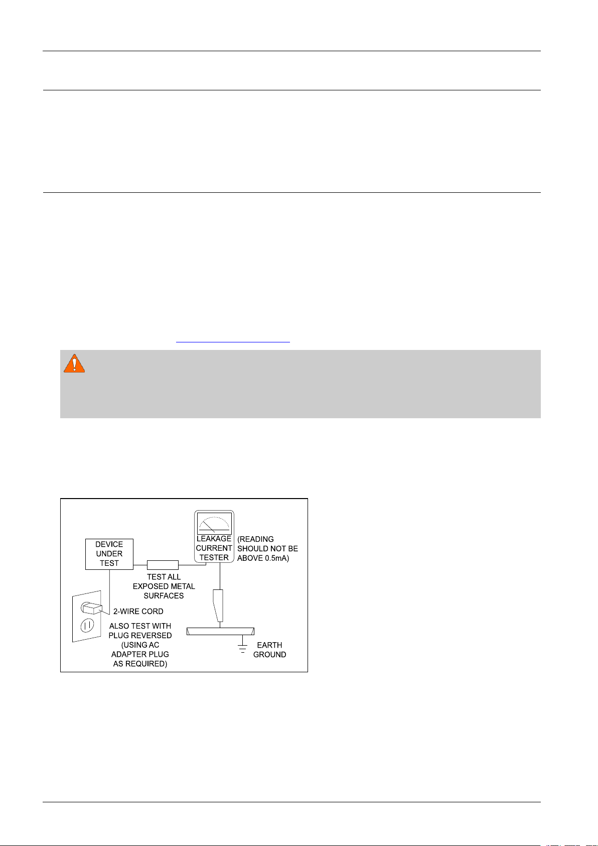
4)LeakageCurrentHotCheckFigure1.1
ACLeakageTest:
WARNING
Donotuseanisolationtransformerduringthistest.Usealeakage-currenttesterorameteringsystemthatcomplies
withAmericanNationalStandardsInstitute(ANSIC101.1,LeakageCurrentforAppliances),andUnderwriters
Laboratories(ULPublicationUL1410,59.7).
Withtheunitcompletelyreassembled,plugtheACcorddirectlyintoa120VACoutlet.Withtheunit’spowerswitched
fromtheONtotheOFFposition,measurethecurrentbetweenaknowngroundandallexposedmetalparts.
KnownGrounds-Earth
KnownMetalparts-Screwheads,MetalCabinets,etc.
Figure1.1ACLeakageTest
1-1Copyright©1995-2012SAMSUNG.Allrightsreserved.
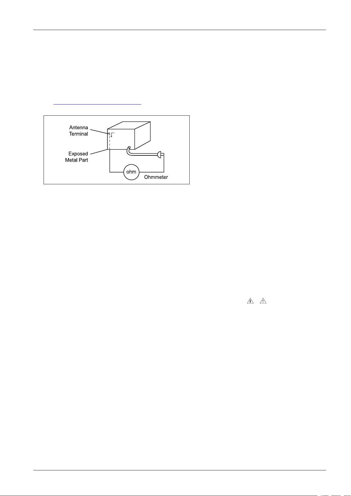
5)InsulationResistanceColdCheck:
Ante nna
Term inal
ohm
Expo s ed
Meta l Pa rt
Ohmmet er
(1)Withtheunit’sACplugdisconnectedfromtheACsource,connectanelectricaljumperacrossthetwoACprongs.
(2)SetthepowerswitchtoON.
(3)MeasuretheresistancebetweentheshortedACplugandanyexposedmetallicparts.
Example:Screwheads,MetalCabinets,AntennaPort,etc.Ifanyoftheexposedmetallicpartshasareturnpathto
thechassis,themeasuredresistanceshouldbebetween1and5.2megohms.Ifthereisnoreturnpath,themeasured
resistanceshouldbe“innite”.Iftheresistanceisoutsidetheselimits,ashockhazardmightexist.
SeeFigure1.2
Figure1.2InsulationResistanceT est
InsulationResistanceTest
1.Precaution
6)Components,partsandwiringthatappeartohaveoverheatedorthatareotherwisedamagedshouldbereplacedwith
partsthatmeettheoriginalspecications.Alwaysdeterminethecauseofdamageoroverheating,andcorrectany
potentialhazards.
7)Observetheoriginalleaddress,especiallynearthefollowingareas:
Antennawiring,sharpedges,andespeciallytheACandhighvoltagepowersupplies.Alwaysinspectforpinched,
out-of-place,orfrayedwiring.Donotchangethespacingbetweencomponentsandtheprintedcircuitboard.Checkthe
ACpowercordfordamage.Makesurethatnowiresorcomponentstouchthermallyhotparts.
8)ProductSafetyNotice:
Someelectricalandmechanicalpartshavespecialsafety-relatedcharacteristicswhichmightnotbeobviousfromvisual
inspection.Thesesafetyfeaturesandtheprotectiontheygivemightbelostifthereplacementcomponentdiffersfrom
theoriginal–evenifthereplacementisratedforhighervoltage,wattage,etc.
9)Componentsthatarecriticalforsafetyareindicatedinthecircuitdiagrambyshading,
or.
Usereplacementcomponentsthathavethesameratings,especiallyforameresistanceanddielectricstrength
specications.Areplacementpartthatdoesnothavethesamesafetycharacteristicsastheoriginalmightcreate
shock,reorotherhazards.
Copyright©1995-2012SAMSUNG.Allrightsreserved.1-2

1.Precaution
1.2.ServicingPrecautions
1)Servicingprecautionsareprintedonthecabinet.Followthem.
2)Alwaysunplugtheunit’sACpowercordfromtheACpowersourcebeforeattemptingto:
(a)Removeorreinstallanycomponentorassembly ,(b)Disconnectanelectricalplugorconnector,(c)Connecta
testcomponentinparallelwithanelectrolyticcapacitor.
3)Somecomponentsareraisedabovetheprintedcircuitboardforsafety.Aninsulationtubeortapeissometimesused.
Theinternalwiringmaybeclampedtopreventcontactwiththermallyhotcomponents.Reinstallallsuchelements
totheiroriginalposition.
4)Afterservicing,alwayscheckthatthescrews,componentsandwiringhavebeencorrectlyreinstalled.Makesurethat
theportionaroundtheservicedparthasnotbeendamaged.
5)ChecktheinsulationbetweenthebladesoftheACplugandaccessibleconductiveparts(examples:metalpanels,
inputterminalsandearphonejacks).
6)InsulationCheckingProcedure:
DisconnectthepowercordfromtheACsource.Connectaninsulationresistancemeter(500V)tothebladesofthe
ACplug.TheinsulationresistancebetweeneachbladeoftheACplugandaccessibleconductiveparts(seeabove)
shouldbegreaterthan1megohm.
7)NeverdefeatanyoftheB+voltageinterlocks.DonotapplyACpowertotheunit(oranyofitsassemblies)unlessall
solid-stateheatsinksarecorrectlyinstalled.
8)Alwaysconnectatestinstrument’sgroundleadtotheinstrumentchassisgroundbeforeconnectingthepositivelead;
alwaysremovetheinstrument’sgroundleadlast.
CAUTION
Firstreadthe“SafetyPrecautions”sectionofthismanual.Ifsomeunforeseencircumstancecreatesaconictbetweenthe
servicingandsafetyprecautions,alwaysfollowthesafetyprecautions.
1-3Copyright©1995-2012SAMSUNG.Allrightsreserved.

1.Precaution
1.3.PrecautionsforElectrostaticallySensitiveDevices(ESDs)
Somesemiconductor(“solidstate”)devicesareeasilydamagedbystaticelectricity.
SuchcomponentsarecalledElectrostaticallySensitiveDevices(ESDs).
Examplesincludeintegratedcircuitsandsomeeld-effecttransistors.
Thefollowingtechniqueswillreducetheoccurrenceofcomponentdamagecausedbystaticelectricity:
1)Immediatelybeforehandlinganysemiconductorcomponentsorassemblies,draintheelectrostaticchargefromyour
bodybytouchingaknownearthground.Alternatively,wearadischargingwrist-strapdevice.(Besuretoremoveit
priortoapplyingpower–thisisanelectricshockprecaution.)
2)AfterremovinganESD-equippedassembly,placeitonaconductivesurfacesuchasaluminumfoiltoprevent
accumulationofelectrostaticcharge.
3)Donotusefreon-propelledchemicals.ThesecangenerateelectricalchargesthatdamageESDs.
4)Useonlyagrounded-tipsolderingironwhensolderingorunsolderingESDs.
5)Useonlyananti-staticsolderremovaldevice.Manysolderremovaldevicesarenotratedas“anti-static”(thesecan
accumulatesufcientelectricalchargetodamageESDs).
6)DonotremoveareplacementESDfromitsprotectivepackageuntilyouarereadytoinstallit.
MostreplacementESDsarepackagedwithleadsthatareelectricallyshortedtogetherbyconductivefoam,aluminum
foilorotherconductivematerials.
7)ImmediatelybeforeremovingtheprotectivematerialfromtheleadsofareplacementESD,touchtheprotectivematerial
tothechassisorcircuitassemblyintowhichthedevicewillbeinstalled.
8)MinimizebodymotionswhenhandlingunpackagedreplacementESDs.Motionssuchasbrushingclothestogether,or
liftingafootfromacarpetedoorcangenerateenoughstaticelectricitytodamageanESD.
Copyright©1995-2012SAMSUNG.Allrightsreserved.1-4

2.ProductSpecication
2.ProductSpecication
2.1.ProductFeature
■HW-F550
•310W(80Wx2+150W)
•2.1CH,WirelessSubwoofer(Aactive)
-DolbyDigital,DTS2.0
-1Analog/1Optical
-HDMIOUT1/HDMIIN1
-SmartV olumeII
-VirtualSurround(Music/News/Movie/Drama/Game/Sports/Off)
-3DSOUNDPlus
-BLUETOOTH
-USBHOST
-AirTrackOn
-SoundShare
2-1Copyright©1995-2012SAMSUNG.Allrightsreserved.
2.ProductSpecication
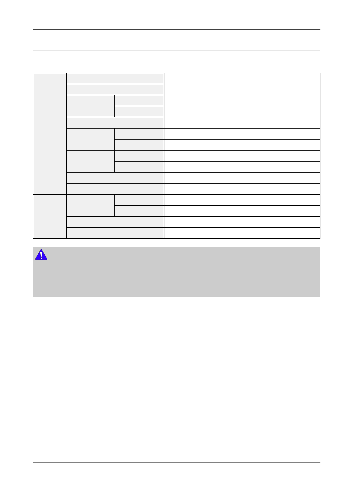
2.2.Specications
■BasicSpecication
PowersupplyDC24V
Standbypowerconsumption0.45W
Power
consumption
USB5V/0.5A
General
Weight
Dimensions
(WxHxD)
Operatingtemperaturerange+41°Fto+95°F
Operatinghumidityrange10%to75%
Ratedoutput
power
Amplier
S/Nratio(analoginput)65dB
Separation(1kHz)65dB
NOTE
•S/Nratio,distortion,separationandusablesensitivityarebasedonmeasurementusingAES(AudioEngineeringSociety)
guidelines.
•SamsungElectronicsCo.,Ltdreservestherighttochangethespecicationswithoutnotice.
•Weightanddimensionsareapproximate.
Mainunit30W
Subwoofer20W
Mainunit4.85Ibs
Subwoofer16.31Ibs
Mainunit37.13x2.17x2.36inches
Subwoofer11.42x14.57x11.42inches
Mainunit80W/CH,3OHM,THD=10%,1kHz
Subwoofer150W,3OHM,THD=10%,100Hz
Copyright©1995-2012SAMSUNG.Allrightsreserved.2-2
2.ProductSpecication
2.3.SpecicationsAnalysis
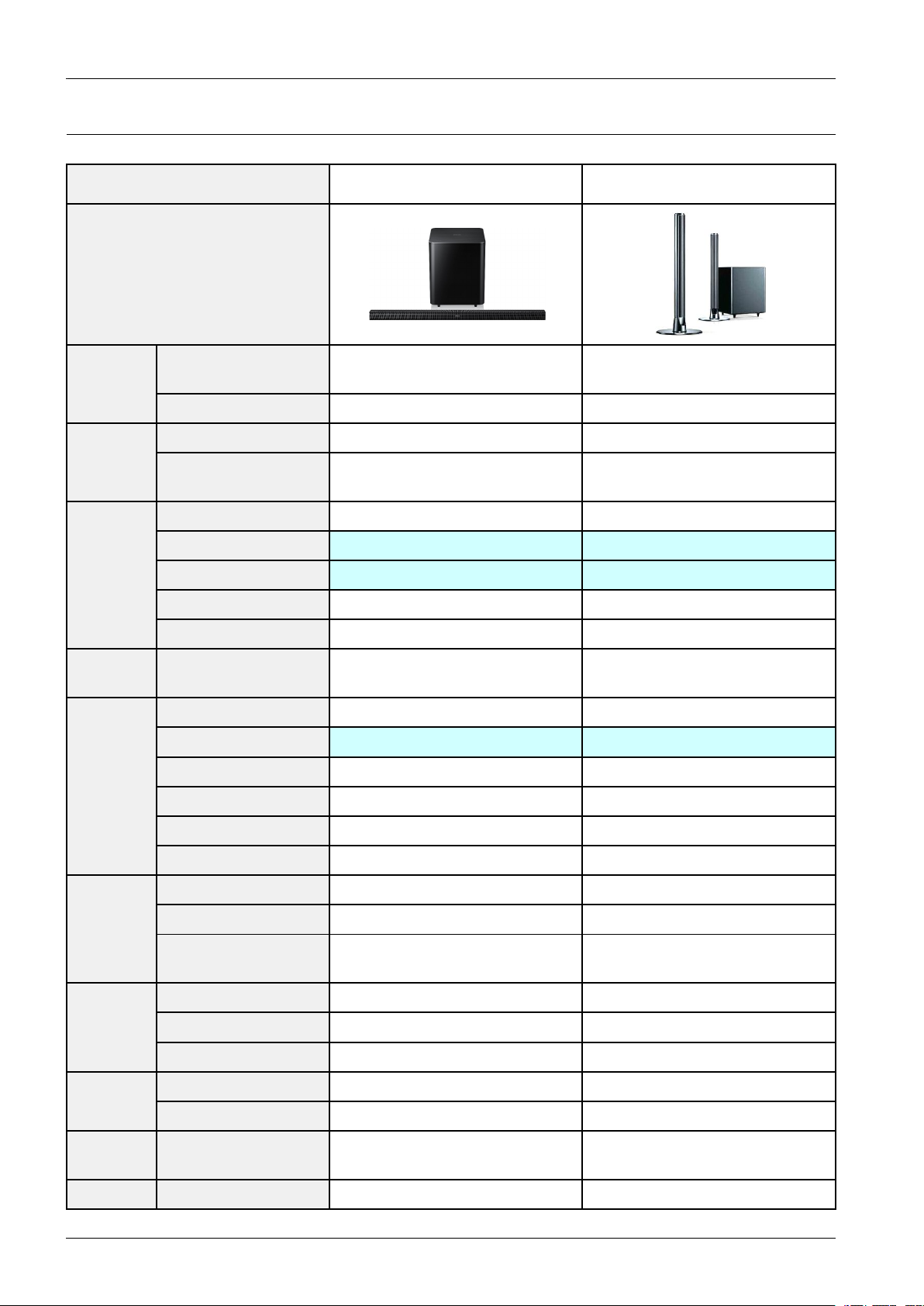
ModelNameHW-F550HW-E550
Photo
Compatible
Output
Power
Media
Extra
Features
DVD
(Video)
DSP
RMS(10%THD),
REF:1ch
OutputPower(ch)80Wx2+150W80Wx2+150W
DiscplaybackN/AN/A
iPodDock
(selectedregiononly)
WirelessReady--
AirTrackOnOX
SoundShareOX
USBHOSTOO
BluetoothOO
ProgressiveScan
(NT/PAL)
VirtualSurroundOO
3DSOUND3DSoundPlus3DSound
ASC--
SmartV olumeSmartVolumeIISmartVolumeII
310W310W
--
--
AudioUpscale--
PowerBass--
DolbyDigital/PlusDolbyDigital2.0DolbyDigital2.0
DolbyT rueHDN/AN/A Audio
Decoding
In/Out
Optical
Jack
HeadphoneHeadphoneJack(3.5Φ)--
2-3Copyright©1995-2012SAMSUNG.Allrightsreserved.
DTS/DTS-HD
(HR/MA)
Componentout--
HDMIOut(CEC)OO Video
HDMIInputOO
MiniJackAudioInAUX1(3.5φ)AUX1(3.5φ) Audio
RCAInput--
In(DigitalIn)O(1)O(1)
DTSDTS
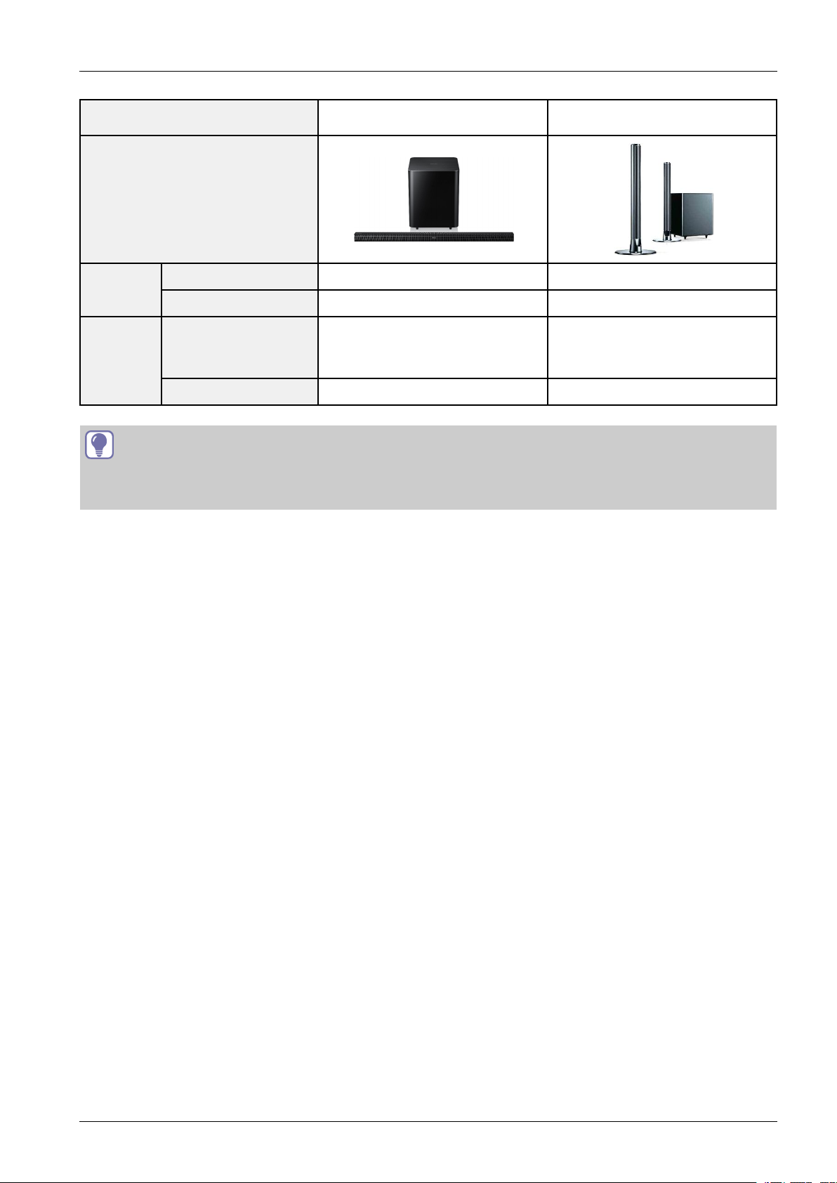
ModelNameHW-F550HW-E550
Photo
2.ProductSpecication
O:FeatureIncluded
X:NotIncluded
Tuner
FM--
PresetMemory--
InternalType
Speaker
Type(Sat/T allboy)
(MainFrameBuilt-InType)
2way3spk
InternalType
(MainFrameBuilt-InType)
2way3spk
Active(Powered)S/WWirelessActiveWirelessActive
TIP
Copyright©1995-2012SAMSUNG.Allrightsreserved.2-4
2.ProductSpecication
POWER
TV POWER
AH59-02546B
REPEAT
TV VOL TV CH
AUDIO SYNC
SOURCE
AUTO
POWER
SPEAKER
TV SOURCE
TV PRE-CH
TV EXIT
SMART VOLUMESOUND EFFECT
S/W
LEVEL
S/W
LEVEL
VOL
VOL
3D SOUND
PLUS
DRC
TV INFOTV MUTE
SoundShare
MUTE
(S cre w:2 EA)
(H
olde r-s cre w:2EA)
2.4.Accessories
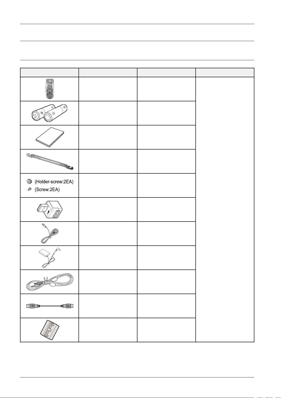
2.4.1.SuppliedAccessories
AccessoriesItemItemcodeRemark
RemoteControlAH59-02546B
Batteries(AAAsize)4301-000116
UserManualAH68-02647X
Bracket-WallMountAH61-03627A
Screw
USBConverterAH59-02572A
PowerCord3903-000525
AdapterBN44-00639A
AUXCableBN39-01286A
AH61-03342A
6001-001961
LocalSamsungDealer
USBcableAH39-01178A
Toroidalferritecore3301-000144
2-5Copyright©1995-2012SAMSUNG.Allrightsreserved.
3.Disassembly&Reassembly
3.Disassembly&Reassembly
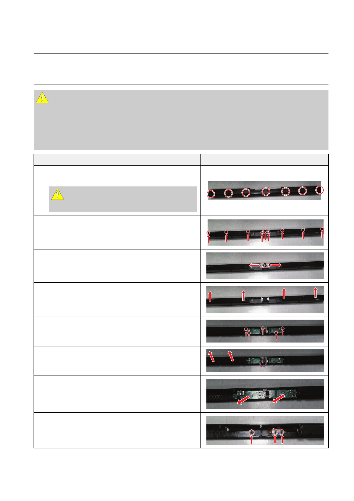
3.1.OverallDisassemblyandReassembly
CAUTION
•Becarefultofollowthedisassemblysequencedescribedinthemanual.Otherwise,theproductmaybedamaged.
•BesuretocarefullyreadandunderstandthesafetyinstructionsbeforeperforminganyworkastheICchipson
thePCBarevulnerabletostaticelectricity.
•Inordertoassemblereversetheorderofdisassembly .
DescriptionDescriptionPhoto
1.Loosen7screwsattheRearCover.
:M,3X10,B
CAUTION
Becarefulnottomakeanyscratchesasyouremovethem.
2.Loosen9screwsattheRearCover.
:M,3X10,B
3.Open2JackCoversattheRearCover.
4.PulltheRearCoverSlowly.
5.Loosen5screwsattheRearCover.
:M,3X10,B,M,3X5,S
UnplugAllConnectorsontheMainPCB.
6.PulltheLeftSpeaker.
RemovetheHDMIPCB
7.RemovetheMainASSY.
8.Loosen3screwsattheIRPCBandOLEDDisplay.
:M,3X10,B
Copyright©1995-2012SAMSUNG.Allrightsreserved.3-1
3.Disassembly&Reassembly
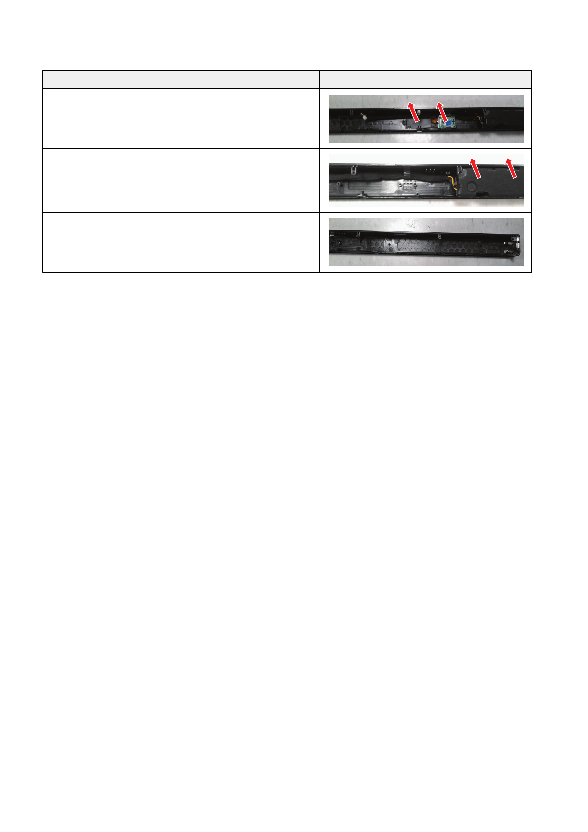
DescriptionDescriptionPhoto
9.RemovetheIRPCBandOLEDDisplay.
10.PulltheRightSpeaker.
11.Finish.
3-2Copyright©1995-2012SAMSUNG.Allrightsreserved.
4.Troubleshooting
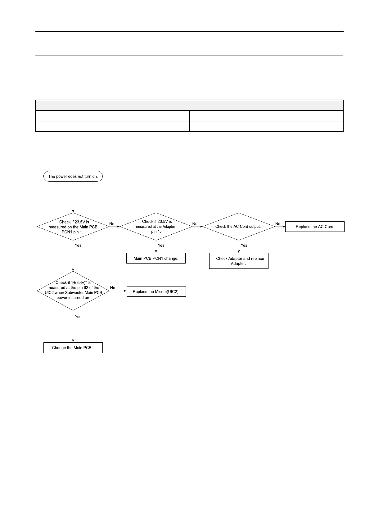
Check if 23.5V is
me asu red on th e Main P CB
PCN1 pin 1.
Yes
Check if 23.5V is
mea sur ed at the Adap ter
pin 1 .
Main PC B P CN1 cha nge .
No No No
Yes
The powe r doe s n ot tu rn on .
Change the Main PC B.
Yes
Check if “H(3.4v )” is
me asu red a t the pin 6 2 of the
UIC2 whe n Subwoo fer Main P CB
power is turn ed o n.
Re place the AC C ord .
Re place the Micom (UIC2).
Check Ada pte r an d re pla ce
Ada pte r.
Check the AC Cord o utpu t.
Yes
No
4.1.CheckpointsbyErrorMode
V oltage/DIV1V/div
TIME/DIV500ms/div
4.1.1.NoPower
4.Troubleshooting
OscilloscopeSettingV alues
Copyright©1995-2012SAMSUNG.Allrightsreserved.4-1
4.Troubleshooting
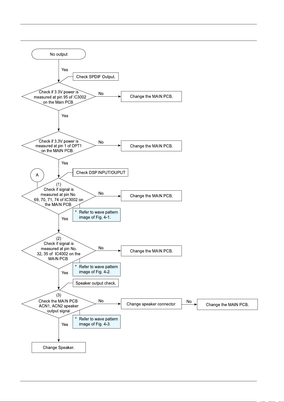
(1)
Che ck if signa l is
me a s u re d a t pin No.
69 , 70 , 71, 74 of IC30 02 on
the MAIN PCB.
Check if 3.3 V po we r is
measured at pin 95 of IC3 002
on the Main PCB.
Ye s
Cha nge the MAIN P C B.
No
No output
Ye s
Che ck S P DIF O utpu t.
Che ck DS P INPUT/O UP UT
Cha nge s pe a ke r co nne ctor.
Che ck if 3.3V powe r is
me a s u re d a t pin 1 of OP T1
on th e
MAIN P C B.
(2)
Che ck if signa l is
me a s u re d a t pin No.
32, 35 of IC400 2 on the
MAIN P C B.
Che ck the MAIN P C B
ACN1, ACN2 s pe a ke r
output signal
* Re fer to wa ve pa tte rn
image of Fig. 4-2.
(3)
Cha nge S pe a ke r.
Ye s
No
No
No
No
No
Spea ke r outp ut che ck.
* Re fer to wa ve pa tte rn
image of Fig. 4-1.
* Re fer to wa ve pa tte rn
image of Fig. 4-3.
Ye s
Ye s
A
Cha nge the MAIN P C B.
Cha nge the MAIN P C B.
Cha nge the MAIN P C B.
Cha nge the MAIN P C B.
Ye s
4.1.2.NoSoundoutput(Digital)
4-2Copyright©1995-2012SAMSUNG.Allrightsreserved.
 Loading...