

Samsung HW-D600, HW-D650S User Manual

HW-D600
HW-D650S
AV Receiver System
user manual
imagine the possibilities
Thank you for purchasing this Samsung product.
To receive more complete service,
please register your product at
www.samsung.com/register
Safety Information
Safety Warnings
TO REDUCE THE RISK OF ELECTRIC SHOCK, DO NOT REMOVE THE COVER(OR BACK). NO USER-SERVICEABLE PARTS ARE INSIDE.
REFER SERVICING TO QUALIFIED SERVICE PERSONNEL.
This symbol indicates “dangerous voltage”
CAUTION
RISK OF ELECTRIC SHOCK
DO NOT OPEN
WARNING
To reduce the risk of fi re or electric shock, do not expose this appliance to rain or moisture.
•
To prevent injury, this apparatus must be securely attached to the fl oor/wall in accordance with the installation
•
instructions.
CAUTION
•
Apparatus shall not be exposed to dripping or splashing and no objects fi lled with liquids, such as vases, shall be placed
on the apparatus.
•
The Mains plug is used as a disconnect device and shall stay readily operable at any time.
This product satisfi es FCC regulations when shielded cables and connectors are used to connect the unit to other
equipment. To prevent electromagnetic interference with electric appliances, such as radios and televisions, use shielded
cables and connectors for connections.
inside the product that presents a risk of
electric shock or personal injury.
This symbol indicates important instructions
accompanying the product.
FCC NOTE (
This equipment has been tested and found to comply with the limits for a Class B digital device, pursuant to Part 15 of the
FCC Rules. These limits are designed to provide reasonable protection against harmful interference in a residential
installation.
This equipment generates, uses and can radiate radio frequency energy and, if not installed and used in accordance with the
instructions, may cause harmful interference to radio communications. However, there is no guarantee that interference will
not occur in a particular installation.
If this equipment does cause harmful interference to radio or television reception, which can be determined by turning the
equipment off and on, the user is encouraged to try to correct the interference by one or more of the following measures:
•
Reorient or relocate the receiving antenna.
•
Increase the separation between the equipment and receiver.
•
Connect the equipment into an outlet on a circuit different from that to which the receiver is connected.
•
Consult the dealer or an experienced radio/TV technician for help.
Caution : FCC regulations state that any unauthorized changes or modifi cations to this equipment may void the user's
authority to operate it.
FOR
U.S.A):
License
•
Manufactured under license from Dolby Laboratories. Dolby, Pro Logic and the double-D symbol are trademarks of Dolby
Laboratories.
Manufactured under license under U.S. Patent #’s: 5,451,942; 5,956,674; 5,974,380; 5,978,762; 6,226,616; 6,487,535;
•
7,212,872; 7,333,929; 7,392,195; 7,272,567 & other U.S. and worldwide patents issued & pending.
DTS and the Symbol are registered trademarks, & DTS-HD, DTS-HD Master Audio | Essential, and the DTS logos are
trademarks of DTS, Inc. Product includes software. © DTS, Inc. All Rights Reserved.
2 English

Important Safety Instructions
This device complies with part 15 of the FCC Rules.
Operation is subject to the following two conditions: (1) This device may not cause harmful interference, and (2) this
device must accept any interference received, including interference that may cause undesired operation.
IMPORTANT NOTE:
FCC Radiation Exposure Statement
This equipment complies with FCC radiation exposure limits set forth an uncontrolled environment.
This equipment should be installed and operated with minimum distance 7.9 inches between the radiator and
your body. This transmitter must not be co-located or operating in conjunction with any other antenna or
transmitter.
Canadian Department of Communications Radio Interference Regulations
This digital apparatus (Wireless Internet Radio) does not exceed the Class B limits for radio-noise emissions
from digital apparatus as set out in the Radio Interference Regulations of the Canadian Department of
Communications.
Read these operating instructions carefully before using the unit. Follow all the safety instructions listed
below. Keep these operating instructions handy for future reference.
1) Read these instructions.
2) Keep these Instructions.
3) Heed all warnings.
4) Follow all instructions.
5) Do not use this apparatus near water.
6) Clean only with dry cloth.
7) Do not block any ventilation openings. Install in accordance with the manufacturer's instructions.
8)
Do not install near any heat sources such as radiators, heat registers, stoves, or other apparatus
(including amplifi ers) that produce heat.
9) Do not defeat the safety purpose of the polarized or grounding-type plug. A polarized plug has two
blades with one wider than the other. A grounding type plug has two blades and a third grounding
prong. The wide blade or the third prong are provided for your safety. If the provided plug does not fi t
into your outlet, consult an electrician for replacement of the obsolete outlet.
10)
Protect the power cord from being walked on or pinched particularly at plugs, convenience receptacles,
and the point where they exit from the apparatus.
11) Only use attachment/accessories specifi ed by the manufacturer.
12) Use only with the cart, stand, tripod, bracket, or table specifi ed by the manufacturer, or
sold with the apparatus. When a cart is used, use caution when moving the cart/
apparatus combination to avoid injury from tip-over.
13) Unplug this apparatus during lightning storms or when unused for long periods of time.
14) Refer all servicing to qualifi ed service personnel. Servicing is required when the apparatus has been
damaged in any way, such as power-supply cord or plug is damaged, liquid has been spilled or objects
have fallen into the apparatus, the apparatus has been exposed to rain or moisture, does not operate
normally, or has been dropped.
English 3

Safety Information
Precautions
Ensure that the AC power supply in your house complies with specifi cations listed on the identifi cation sticker
•
located on the back of your product.
Install your product horizontally, on a suitable base (furniture), with enough space around it for ventilation
•
(7.5~10cm / 20~25 inches).
Do not place the product on amplifi ers or other equipment which may become hot.
•
Make sure the ventilation slots are not covered.
Do not stack anything on top of the product.
•
•
To disconnect the product completely from the power supply, remove its plug from the wall outlet.
- If you leave the product unused for a long period of time, disconnect the plug from the wall outlet.
•
During thunderstorms, disconnect the AC plug from the wall outlet. Voltage spikes caused by lightning could
damage the product.
Do not expose the product to direct sunlight or other heat sources. This could cause the product to overheat
•
and malfunction.
•
Protect the product from moisture, excess heat, and equipment creating strong magnetic or electric fi elds (i.e.
speakers.).
•
Disconnect the power cable from the AC supply if the product malfunctions.
•
Your product is not intended for industrial use. It is for personal use only.
•
Condensation may occur if you store your product in cold temperatures. If transporting the product during the
winter, wait approximately 2 hours until the product has reached room temperature before using.
•
The batteries used with this product contain chemicals that are harmful to the environment.
Do not dispose of batteries in the general household trash.
4 English

Contents
SAFETY INFORMATION
2
GETTING STARTED
7
CONNECTIONS
15
2 Safety Warnings
3 Important Safety Instructions
4 Precautions
7 Key features of your new AV Receiver
8 Accessories
9 Description
9 Front Panel
10 Display
11 Rear Panel
12 Remote Control
15 Speaker Positioning
17 Connecting the Speakers
Connecting External Devices/your TV via HDMI
19
20
HDMI Function
21
Connecting to your TV
22
Connecting a DVD or BD(Blu-ray) Player
23 Connecting a Cable, Satellite or Set-top Box
24 Connecting a CD Player
25 Connecting Using the External Amplifi er
26 Connecting an iPod
28 Connecting the FM Antenna
28 Connecting AUX Components
ENGLISH
ENGLISH
SETUP
29
29 Before Using the AV Receiver
29 Home Menu
30 Selecting Digital/HDMI/Analog
31 Setup Menu Tree
34 Audio Setup
34 Selecting a Source Device And Connection Jack
(Digital Audio In)
34 Setting the Speaker Size
36 Connection Setting For Surround Back
37 Setting the Speaker Listening Distance
38 Setting the Speaker Level
39 Setting the Test Tone
40 Setting Dolby Pro Logic Mode
40 Surround Setup
40 Setting Dolby Pro Logic IIx
41 Setting NEO:6 Mode
41 Setting EX/ES Mode
42 Other Settings
42 Audio Sync
42 Tone Control
43 MP3 Enhancer
43 Smart Volume
44 Auto Calibration Setup
45 DRC Setup
45 Dual Mono Setup
46 HDMI Setup
English 5

Contents
OPERATION
47
MISCELLANEOUS
55
47 Using the Surround Modes
47 Using the AUDIO EFFECT Button On the Front of the
Main Unit
48 Using the S.DIRECT Button
49 Using the SUBWOOFER button
49 Listening to the Radio
50 To Listen in Mono/Stereo
50 Presetting Radio Stations
51 Using an iPod
51 Listening to Music (iPod audio function)
51 Watching a Movie (iPod video function)
52 Convenient Functions
52 Sleep Timer Function
53 Mute Function
53 Adjust the Display
53 Reset Function
54 Using Headphones
54 Software Upgrade
55 Operating your TV with the Remote Control
56 Operating your DVD or BD Player with the Remote
Control
OTHER INFORMATION
57 Troubleshooting
58 Product Protection Function
58 Auto Calibration Error List
59 Specifi cations
57
Figures and illustrations in this User Manual are provided for reference only and may differ from actual product
•
appearance.
6 English

01 Getting Started
Getting Started
Key features of your new AV Receiver
Product Features
Digital AV Receiver
This product is a pure digital AV receiver that performs digital signal processing to minimize signal
distortion and loss.
Dolby Digital
Effective audio encoding/decoding technology that provides a vivid surround sound in up to 5.1 channels.
Dolby Pro Logic llx
Dolby Pro Logic IIx is a new technology that provides discrete 7.1 channels out of 2 channel or multi
channel sources.It also provides Music,Movie and Game modes.
Dolby Pro Logic IIx is an improved surround system that is optimized to a 7.1 CH multimedia system,
enabling you to maximize your entertainment experience.
Dolby Pro Logic llz
Dolby Pro Logic IIz adds front height channels to surround sound, creating a 7.1 playback system for
video games, home music, and movies; bringing enhanced spatial effects and enveloping sound.
Dolby Digital EX
Adds a surround back channel for more spacious sound compared to regular 5.1 channel Dolby Digital.
Dolby Digital Plus
Dolby Digital Plus is the next-generation audio technology for all high-definition programming and media.
Dolby True-HD
Dolby True-HD is Dolby’s next-generation lossless technology developed for high-definition disc-based
media.
DTS 96/24
DTS 96/24 encodes standard 16 bit/44.1 kHz sound to 24 bit/96kHz and applies it to a
5.1 CH sound track.
DTS (Digital Theater Systems)
DTS provides a discrete 5.1 CH digital audio signal for both music and movie contents and uses less
compression than Dolby Digital for richer sound.
DTS-HD (Master Audio, High Resolution)
(Digital Theater Systems - High Definition)
DTS-HD Audio provides the highest quality multi-channel sound possible.
It delivers sound quality that matches the clear and vivid images of high-definition video.
DTS
Provides a full range of 6 channels by converting a digital PCM or analog stereo signal using DTS digital
matrix decoding.
English 7
Getting Started
DTS-ES (Extended Surround)
The DTS-ES (Extended Surround) system is a new multi digital signal format that was
developed by Digital Theater Systems Inc.
Supporting full compatibility with the conventional DTS digital surround sound format, the
DTS-ES (Extended Surround) system improves the surround signal for a 360-degree surround effect.
DTS-ES adds an additional rear center surround channel for 6.1 channel sound.
iPod
You can enjoy music files by connecting your iPod/iPhone to the AV Receiver with
the supplied iPod dock.
SFE (Sound Field Effect) Using 32bit Audio Digital Signal Processing
Provides more realistic surround sound with normal stereo audio sources.
Anynet+ (HDMI-CEC) Function
Anynet+ is a function that can be used to operate this AV Receiver with a Samsung TV remote control,
by connecting the receiver to a SAMSUNG TV using an HDMI Cable. (This function is available only in
connection with Samsung TV and DVD player supporting Anynet+(HDMI-CEC).)
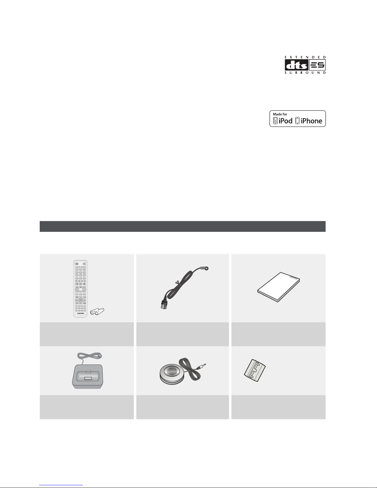
Accessories
Check the box for the supplied accessories listed below.
INPUT SELECT
POWER
TV SOURCE
AMP TV BD DVD
123
456
SLEEPNEO:6 DIMMER
7809
PROLOGIC AUDIO ASSIGN
DSP
MUTE
TUNING
VOL
/CH
S.DIRECT
TONE
MO/ST TUNER MEMORY
SETUP/MENU
INFO
RETURN
EXIT
SAT GAME/TVBD/DVD CD
iPod
TUNER
AV SYNC
AUX
SUB
CROSS
3D SOUND
WOOFER
OVER
ASC
Remote Control (AH59-02370A)/
Batteries (AAA size) (4301-000116)
FM antenna (AH42-00017A) User’s manual (AH68-02354X)
(For Speaker cable)
iPod Dock (AH96-00051A) ASC microphone (AH30-00099A)
8 English
Toroidal Ferrite Core (3301-000144)
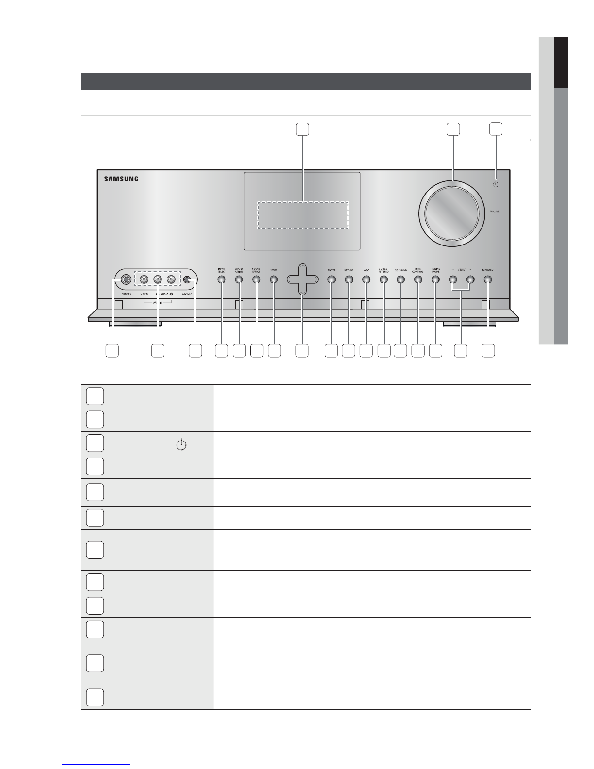
Front Panel
01 Getting Started
Description
1
DISPLAY
1 2
7 8 9 10 11 12 13 14 15 16 17 18 19 20654
Displays the speaker/audio input status, listening mode, etc.
3
VOLUME CONTROL
2
3
POWER BUTTON ( )
PHONES JACK
4
AUX IN JACKS
5
ASC MIC JACK
6
INPUT SELECT BUTTON
7
AUDIO ASSIGN BUTTON
8
SOUND EFFECT BUTTON
9
SETUP BUTTON
10
UP(,), DOWN(.),
LEFT(<), RIGHT(>)
11
BUTTONS
ENTER BUTTON
12
Adjusts the volume level.
Turns the receiver on/off.
Used to connect a set of headphones.
Auxiliary AV input terminals used to connect a camcorder, portable DVD player or
gaming device.
Used to connect the ASC MIC for setting up Auto calibration.
Used to select a source.
FM TV BD/DVD SAT GAME AUX CD IPOD AUDIO IPOD
VIDEO
Toggles to select an input mode for the selected source.
Toggles to select a surround sound mode.
Displays the SETUP menu.
Used to move the cursor up, down, left or right.
Also used to select detailed options in the SOUND EFFECT mode and to change the
tone level.
Used to select an item in the SETUP menu.
English 9
Getting Started
RETURN BUTTON
13
ASC BUTTON
14
S.DIRECT / STEREO
15
BUTTON
3D SOUND BUTTON
16
TONE CONTROL BUTTON
17
TUNING MODE BUTTON
18
SELECT BUTTON
19
MEMORY BUTTON
20
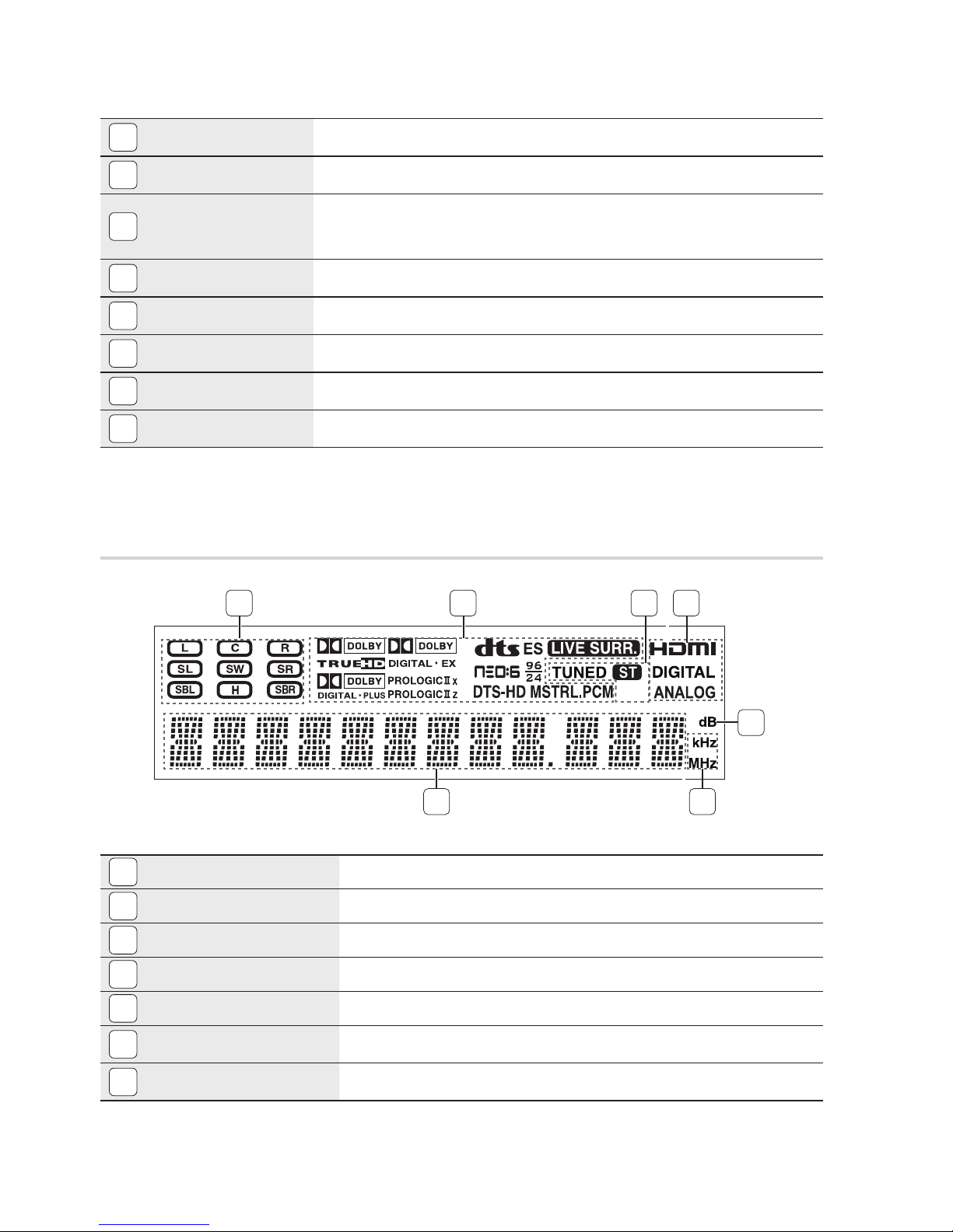
Display
Return to the previous menu.
Used to select the auto calibration mode.
Used to select the S.DIRECT or STEREO mode.
(Output the original signal as it is without applying the sound fi eld effect or any other
sound effect.)
Press to apply 3D Sound effect.
Used to set the bass, treble level and tone to on/off.
Used to select the Manual or Preset mode for FM radio.
Used to change the radio frequency.
Used to set a preset radio frequency.
1 2 3 4
SPEAKER INDICATORS
1
LISTENING MODE INDICATORS
2
TUNING INDICATORS
3
AUDIO INPUT INDICATORS
4
SPEAKER LEVEL INDICATOR
5
RADIO FREQUENCY INDICATORS
6
5
67
Displays sound producing speakers.
Displays the current listening mode and audio source.
Displays the status of the current radio broadcast.
Displays the audio input signal type of the currently connected external audio source.
Displays the speaker level.
Displays the current radio frequency range.
MESSAGE DISPLAY
7
10 English
Informs you of the status of the receiver.
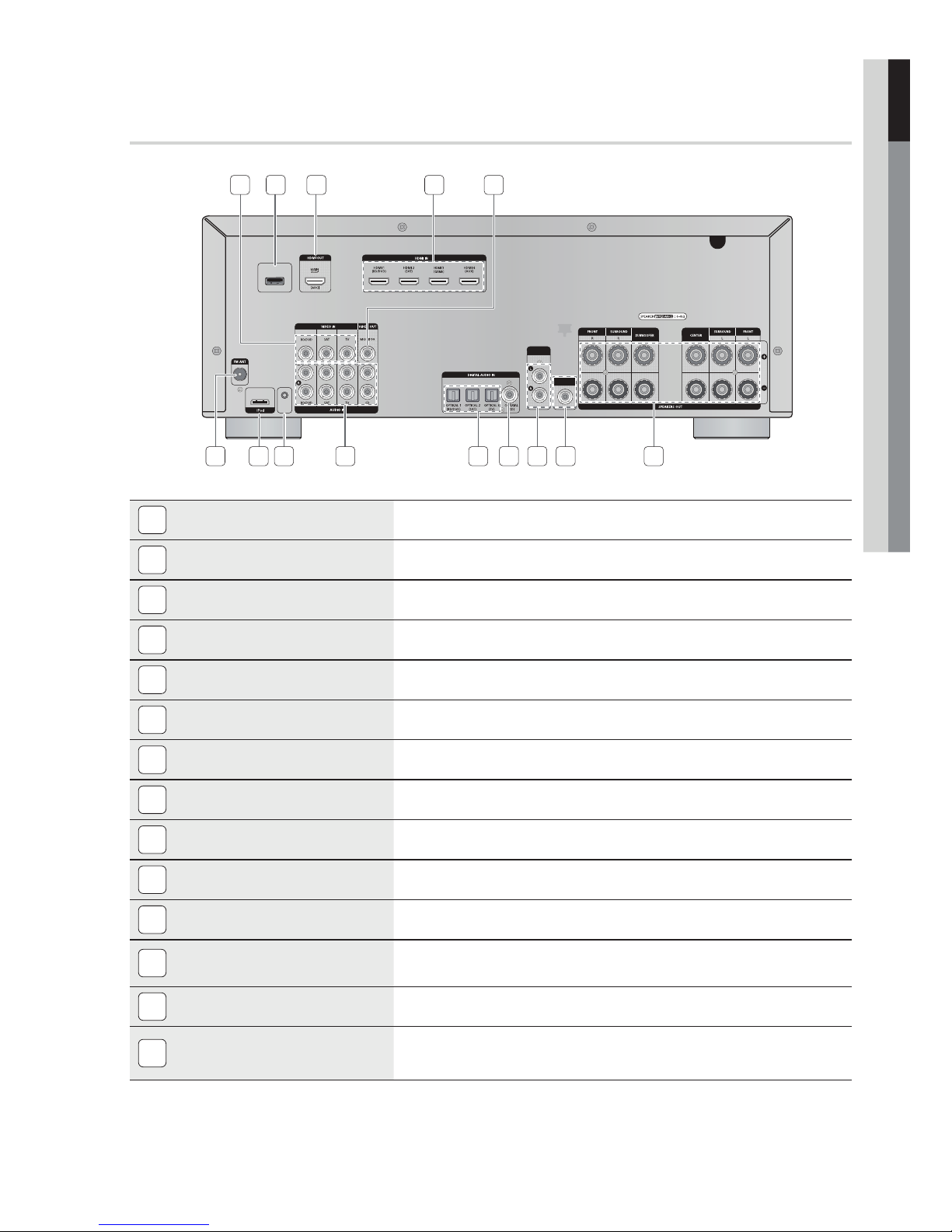
Rear Panel
01 Getting Started
VIDEO IN JACKS
1
USB PORT
2
HDMI OUT JACK
3
421
ONLY FOR
UPDATE
ONLY FOR
SERVICE
6 8 1312
53
SURROUND
BACK OUT
10 1197 14
Receives the video signal from a video player (
Can be only used for fi rmware upgrades.
Outputs digital video and audio signals simultaneously using an HDMI cable.
SUBWOOFER
OUT
BD/DVD, SAT, TV
).
HDMI IN JACKS
4
VIDEO OUT JACK
5
FM ANTENNA JACK
6
iPod JACK
7
ONLY FOR SERVICE JACK
8
AUDIO IN JACKS
9
OPTICAL IN JACKS (DIGITAL AUDIO IN)
10
COAXIAL IN JACK (DIGITAL AUDIO IN)
11
SURROUND BACK OUT JACKS
12
SUBWOOFER AUDIO OUT JACK
13
SPEAKERS OUT TERMINALS
14
Receives digital video and audio signals simultaneously using an HDMI cable.
Outputs the video signal to a monitors (TV, Projector etc).
Connect the FM antenna.
Receives the audio/video signal from an iPod.
Used for the service repair.
Receives the audio signal from a video player (BD/DVD, SAT, TV).
Receives the digital optical audio signal.
Receives the digital coaxial audio signal.
Outputs the "Surround Back" analog signal to the external amplifi er.
Connect the subwoofers. (Active subwoofer only)
Speaker connection terminals.
English 11
Getting Started
Tour of the Remote Control
Remote Control
1
2
3
4
5
6
7
8
9
10
POWER
TVAMP BD DVD
INPUT SELECT
TV SOURCE
123
456
NEO:6
SLEEP DIMMER
7809
DSP
TUNING
/CH
VOL
AUDIO ASSIGNPROLOGIC
MUTE
S.DIRECT
20
21
22
23
24
25
26
27
28
29
11
12
13
14
15
16
17
18
19
TONE
SETUP/MENU
RETURN
AV SYNC
ASC
WOOFER
MO/ST TUNER MEMORY
INFO
EXIT
SAT GAME/TVBD/DVD CD
TUNER
iPod
AUX
SUB
CROSS
3D SOUND
OVER
30
31
32
33
34
35
36
12 English

01 Getting Started
1
2
3
4
5
6
7
8
9
10
11
12
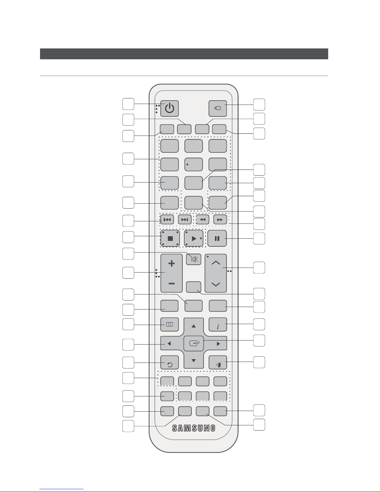
POWER BUTTON
TV BUTTON
AMP BUTTON
NUMBER BUTTONS
NEO : 6 BUTTON
PROLOGIC BUTTON
SKIP BUTTONS
STOP/PLAY BUTTON
MUTE BUTTON
VOLUME CONTROL BUTTONS
MO/ST BUTTON
TONE BUTTON
Turns the receiver on/off.
To change to TV mode, press the TV button.
To change to AMP mode, press the AMP button.
Used to select a TV channel.
Select the desired NEO:6 mode.
Select the desired Dolby Pro Logic audio mode.
Press to skip backwards or forwards on a connected DVD/BD player or iPod.
Press to stop/start playback on a connected DVD/BD player or iPod.
Mutes the sound of a connected device.
Adjusts the volume of the selected device.
Select MONO or STEREO for radio broadcasts.
You can adjust the bass and treble level.
13
14
15
16
17
18
19
20
21
22
23
24
SETUP/MENU BUTTON
UP/DOWN/LEFT/RIGHT BUTTONS
RETURN BUTTON
FUNCTION SELECTOR BUTTONS
AV SYNC BUTTON
ASC BUTTON
SUBWOOFER BUTTON
INPUT SELECT,
TV SOURCE BUTTON
BD BUTTON
DVD BUTTON
SLEEP BUTTON
DIMMER BUTTON
Displays the SETUP menu.
Used to navigate the menus.
Used to return to the previous menu from the SETUP menu.
Used to select an input source.
Used to select the Audio Delay Mode.
Used to set the Auto Sound Calibration function.
Used to select the Subwoofer.
Toggles to fi nd and select an input source.
Press to select a connected TV's video source.
To change to BD mode, press the BD button.
To change to DVD mode, press the DVD button.
Used to set the Sleep Timer.
Adjusts the brightness of the display.
25
26
DSP BUTTON
AUDIO ASSIGN BUTTON
Used to select the SFE mode.
Toggles to select an input mode for the selected source.
English 13
Getting Started
27
28
29
30
31
32
33
34
35
36
SEARCH BUTTON
PAUSE BUTTON
TUNING/CHANNEL BUTTONS
S.DIRECT BUTTON
TUNER MEMORY BUTTON
INFO BUTTON
ENTER BUTTON
EXIT BUTTON
3D SOUND BUTTON
CROSS OVER BUTTON
Press to search backwards or forwards.
Pauses playback on a connected device.
Used to change the radio broadcasting frequency or TV channel.
Press to select S.DIRECT mode.
Used to set a preset radio frequency.
Display information on the connected device currently being used.
Used to select an item in the SETUP menu.
Exits the SETUP menu.
Press to apply 3D Sound effect.
Press to adjust the crossover frequency.
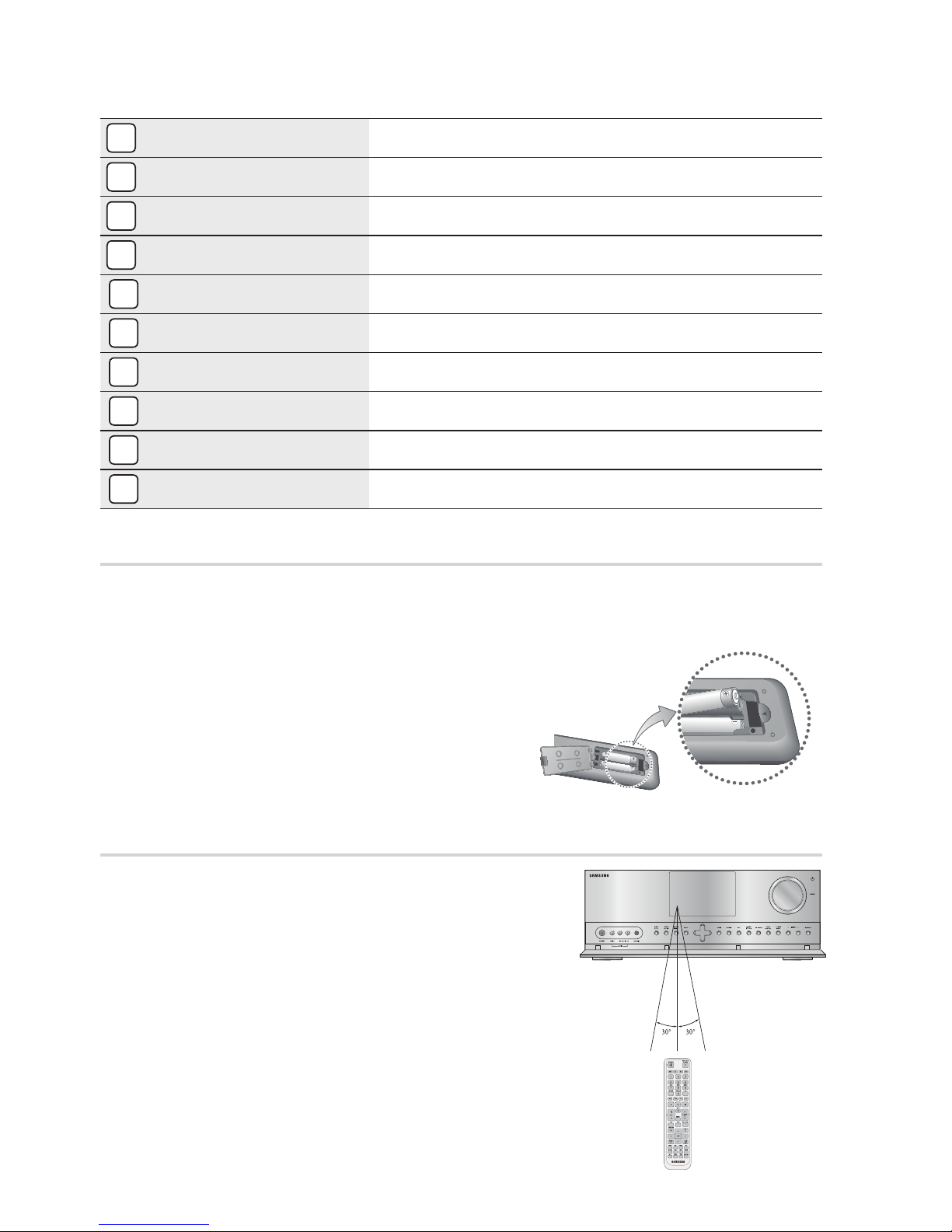
Installing batteries in the Remote Control
NOTE
✎
Follow these precautions to avoid leaking or cracking cells:
Place batteries in the remote control so they
match the polarity : (+) to (+) and (–) to (–).
Assuming typical AVR usage, the batteries last for
about one year.
Use the correct type of batteries. Batteries that
look similar may differ in voltage.
Always replace both batteries at the same time.
Do not expose the batteries to heat or a fl ame.
* Battery size: AAA
Operation Range of the Remote Control
The remote control can be used up to approximately 23 feet/7
meters in a straight line. It can also be operated at a horizontal
angle of up to 30° from the remote control sensor.
14 English
02 Connections
Connections
This section involves various methods of connecting the AV receiver to other external components.
Before moving or installing the product, be sure to turn off the power and disconnect the power cord.
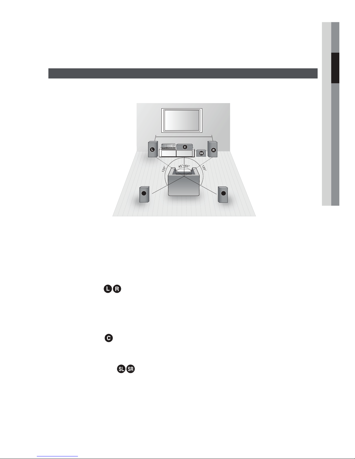
Speaker Positioning
* Speakers are provided with model HW-D650S only. Model HW-D600 does not come with
speakers.
6.6~9.8 feet (2~3m)
AV RECEIVER
SL SR
Position of AV Receiver
Place the AV Receiver on a dedicated stand or rack.
Subwoofer
The position of the subwoofer is not so critical. Place it anywhere you like.
g
Front Speakers
Place these speakers in front of your listening position, facing inwards (about 45°) toward you.
Place the speakers so that their tweeters will be at the same height as your ears.
Align the front face of the front speakers with the front face of the center speaker or place them slightly in
front of the center speaker.
Center Speaker
It is best to install it at the same height as the front speakers.
You can also install it directly over or under the TV.
Surround Speakers
Place these speakers behind your listening position.
If there isn't enough room, place these speakers so they face each other.
Place them about 2 to 3 feet (60 to 90cm) above your ears, facing slightly downward.
Unlike the front and center speakers, the surround speakers are used to handle mainly sound effects and
sound will not come from them all the time.
English 15
Connections
SBL
SBR
FHL
SBL
FHL
Surround Back Speakers
If you are using two rear center speakers, place them behind the listening position.
Place the surround back speaker about 2.3-3.3 feet (70 cm to 1 m).
Front Height Speakers
When using Dolby Pro Logic IIz, place the Surround Back Speakers on the FHL, FHR position above the
front L and front R speakers at least 3.3 feet(1 m) above each one.
NOTE
✎
When you attach the speakers to the wall, make sure to fasten them tightly so they do not fall off.
FHR
(Option)
(Option)
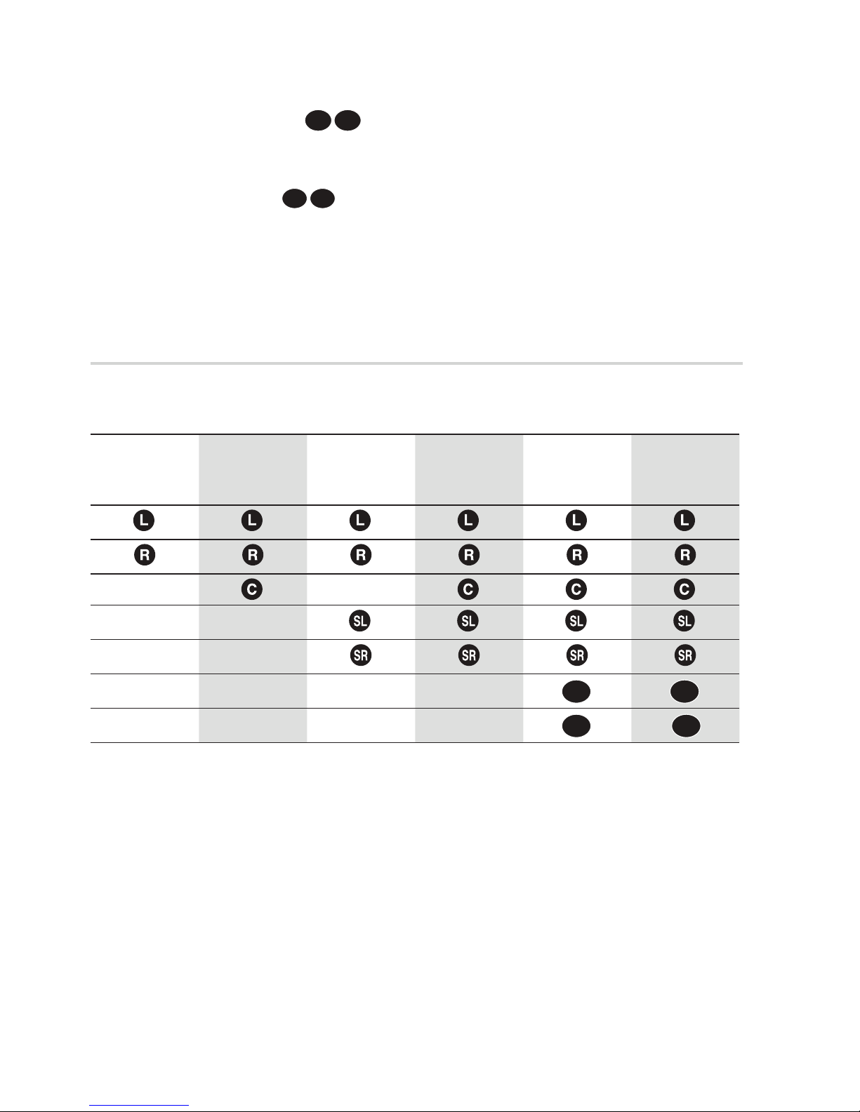
Speaker Confi guration
For the best surround-sound experience, you should connect fi ve speakers and a subwoofer.
The following table shows which channels you should use based on the number of speakers you have.
7 speakers
(DPL IIz)
(Option)
2 speakers 3 speakers 4 speakers 5 speakers
7 speakers
(DPL IIx)
(Option)
NOTE
✎
If you place a speaker near your TV set, screen color may be distorted because of the magnetic fi eld
generated by the speaker. If this occurs, place the speaker away from your TV set.
If you have a external stereo Amplifi er and two Speakers and connect them, you can constitute 7
speaker confi guration.
Also if you have a external active subwoofer, you can connect it.
16 English
SBR
FHR
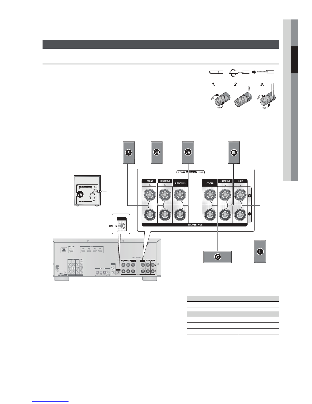
Connecting the Speakers
BACK O
Connecting Speaker Wire
Loosen the knob by turning counterclockwise.
1.
Insert the bare part of the wire into the hole in the side of each
2.
terminal.
Tighten the knob by turning clockwise to secure the wire.
3.
02 Connections
ACTIVE SUBWOOFER
(not supplied)
ONLY FOR
UPDATE
ONLY FOR
SERVICE
SURROUND (R)FRONT (R)
SUBWOOFER
OUT
SURROUND
SURROUND
UT
BACK OUT
SUBWOOFER
OUT
SUBWOOFER
SURROUND (L)
CENTER
FRONT (L)
Model HW-D600
AV Receiver HW-D600
Model HW-D650S
AV Receiver HW-D600
FRONT SPEAKER PS-FC560S
CENTER SPEAKER PS-CC560S
SURROUND SPEAKER PS-RC560S
SUBWOOFER SPEAKER PS-WC560S
English 17
Connections
S
S
OUT
NOTE
✎
Speakers are provided with model HW-D650S only. Model HW-D600 does not come with
speakers. Contact a Samsung Electronics retailer for purchasing.
Keep the subwoofer speaker out of reach of children to prevent them from inserting their hands
or objects into the duct (hole).
Never touch speaker terminals while the power is on. Doing so could result in electric shock.
Make sure the polarities (+ and -) are correct.
If you want to use a active subwoofer speaker (not supplied), connect a subwoofer speaker into
the SUBWOOFER OUT terminal in the rear panel.
By using an external amplifi er, you can connect the surround back speakers (SBL/SBR) or front
height speakers(FHL/FHR) to improve your system up to a 7.1 channel system.
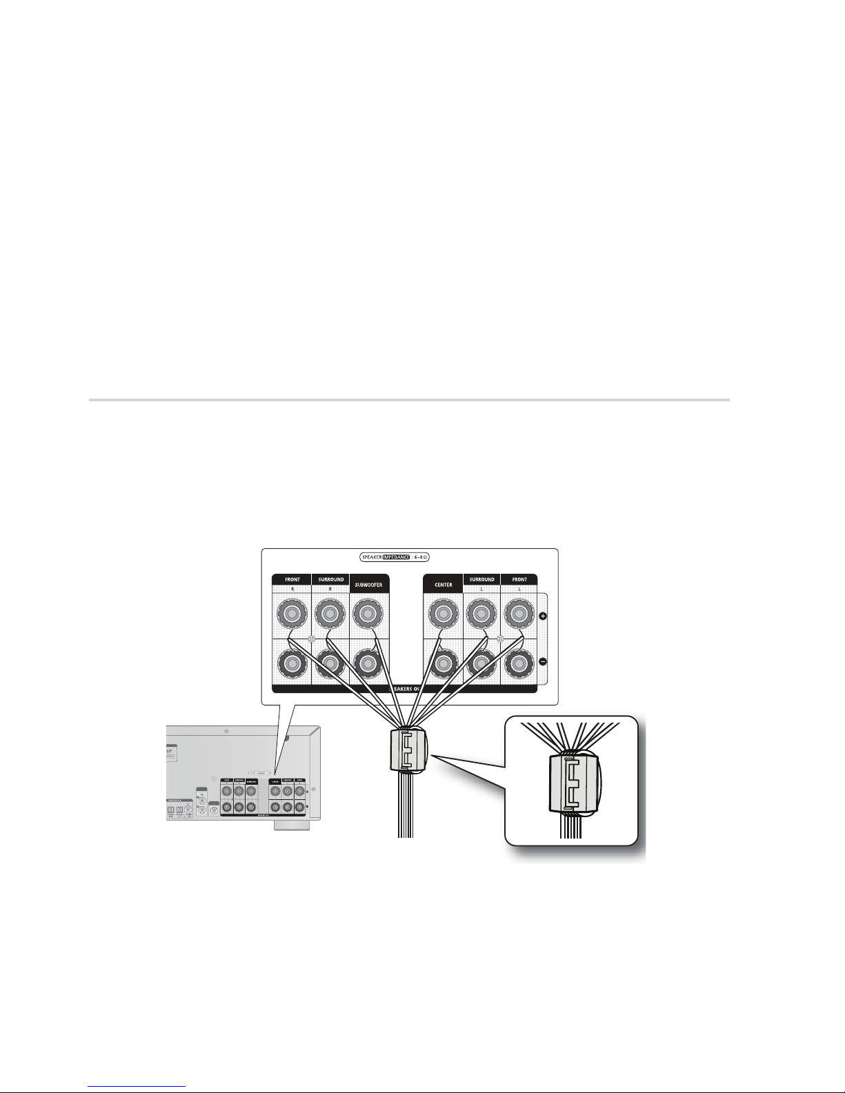
Attaching the Toroidal Ferrite Core to the Speaker Cable
Open the toroidal ferrite cores by pulling the lock lever.
1.
Arrange all the speaker cables that are connected to the unit and make a loop.
2.
Attach the ferrite core as close as possible to the unit.
•
Place the toroidal ferrite core on the looped speaker cable as shown, and then press it closed it
3.
until you hear a click.
SURROUND
URROUND
BACK OUT
BACK OUT
SUBWOOFER
UBWOOFER
OUT
18 English
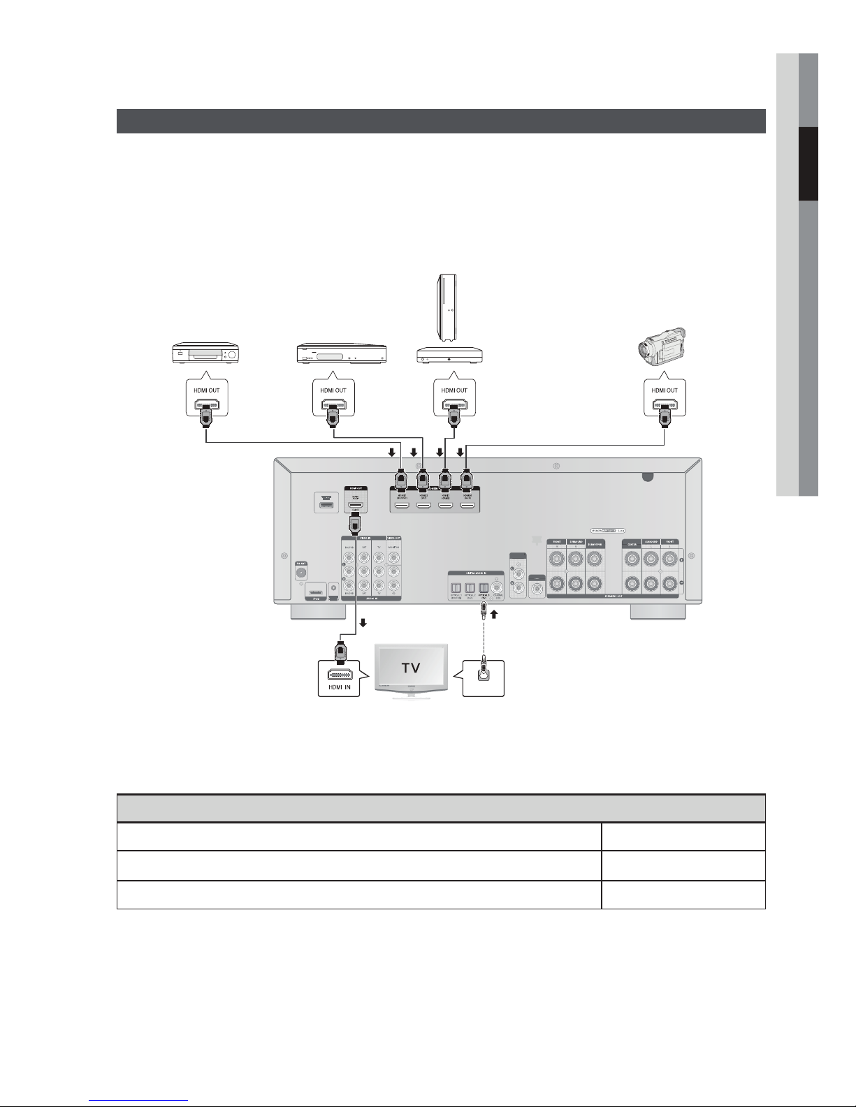
Connecting External Devices/your TV via HDMI
S
R
OUT
HDMI is a digital standard interface for connection to such devices as a TV, projector, DVD player, Blu-ray
player, set-top box and more.
HDMI removes any loss of signal from analog conversion, enabling you to enjoy video and audio sound
quality as it was originally created in the digital source.
By connecting through the HDMI(High-Defi nition Multimedia Interface) interface, you can play back digital
video and audio.
Game console
DVD or
Blu-ray Player
SAT
(Cable/Satellite/Set-top box)
or
HDTV Tuner
Camcorder
(HDTV Terrestrial
Receiver)
02 Connections
ONLY FOR
UPDATE
SURROUND
SURROUND
BACK OUT
BACK OUT
SUBWOOFER
UBWOOFE
OUT
ONLY FOR
SERVICE
• Connect it if you want to use
Anynet+. (If connected TV support
OPTICAL
OUT
ARC, it is not necessary to
connect the OPTICAL OUT.)
High-bandwidth Digital Content Protection System (HDCP) support
To play digital contents through the HDMI connection, both the connected external device and TV must
support High-bandwidth Digital Content Protection System (HDCP). This product supports HDCP.
Compatibility with a TV Supporting HDMI
A TV with an HDMI jack. Video/Audio
A TV with a DVI-D jack (TV supporting HDCP) Video
A TV with a DVI-D jack (TV not supporting HDCP) -
NOTE
✎
Audio from SACD discs will not be heard with this connection. To play a DVD disc whose copyright is
protected by CPPM, use a player supporting CPPM.
The quality of the audio output through the HDMI jack (sampling frequency and bit rate) may be limited by the
performance of the connected device.
Since HDMI connection supports both video and audio, you don’t have to connect an additional audio cable.
English 19

Connections
HDMI Function
Using Anynet+ (HDMI-CEC)
Anynet+ is a function that enables you to control other Samsung Devices with your Samsung TV's
remote control. Anynet + can be used by connecting this AV Receiver to a SAMSUNG TV using an
HDMI Cable. This is only available with SAMSUNG TVs and SAMSUNG AV Products that support
Anynet+.
Connect the AV receiver to a Samsung TV with an HDMI cable. (See page 19)
1.
Set the Anynet+ function on your TV.
2.
(See the TV instructions manual for more information.)
You can operate the volume on the AV receiver by using Volume buttons on the TV remote
•
control.
To Turn on Anynet+
Press the SETUP/MENU button on the remote control.
1.
Each time the button is pressed, the mode switches between INPUT and SETUP OFF.
•
2.
Press the ▲▼ buttons to select OPTION, and then press the ENTER button.
Press the ▲▼ buttons to select HDMI SETUP, and then press the ENTER button.
3.
4.
Press the ▲▼ buttons to select HDMI ANYNET+, and then press the ENTER button.
Press the ▲▼ buttons to set ANYNET+ to ON, and then press the ENTER button.
5.
To exit setup mode
Press the SETUP/MENU or EXIT button on the remote control.
•
SETUP OFF appears on the display and Setup Mode is exited.
NOTE
✎
If you use an HDMI cable to connect a Samsung TV to your AV Receiver, you can operate the AV
receiver using the TV’s remote control. This function is available only in connection with Samsung
TV and DVD player supporting Anynet + (HDMI-CEC).
Please check your TV for the ANYNET+ logo. If your TV has an ANYNET+ logo, then it supports
the Anynet+ function.
When you are making Anynet+ connection, do not connect more than two AV receivers (Anynet+
installed). Otherwise, it can cause a malfunction.
20 English

ONLY FOR
D
B
T
OUT
UPDATE
ONLY FOR
SERVICE
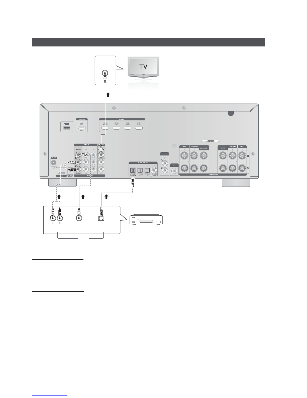
Connecting to your TV
SURROUND
SURROUN
BACK OUT
ACK OU
SUBWOOFER
SUBWOOFER
OUT
or
02 Connections
VIDEO
IN
OPTICAL
OUT
AUDIO
OUT
Video Connection
Connect the Video cable (not supplied) from the VIDEO OUT (MONITOR) jack on the back of your AV Receiver to
the Video Input jack on your TV.
Audio Connection
Connect the Digital Input (OPTICAL 3) on your AV Receiver to the Digital Output of the TV.
OR
Connect AUDIO IN (TV) on your AV Receiver to the Audio Out of the TV.
English 21
Connections
S
OUT
ONLY FOR
UPDATE
ONLY FOR
SERVICE
Connecting a DVD or BD(Blu-ray) Player
VIDEO
IN
or
SURROUND
URROUND
BACK OUT
BACK OUT
SUBWOOFER
SUBWOOFER
OUT
or
AUDIO
OUT
VIDEO
OUT
OPTICAL
OUT
DVD or BD Player
or
Video Connection
Connect a Video cable (not supplied) from the VIDEO IN (BD/DVD) jack on the back of your AV Receiver to the
Video Output jack on your DVD/BD player.
Audio Connection
Connect the Digital Input (OPTICAL 1) on your AV Receiver to the Digital Output of the DVD/BD player.
OR
Connect AUDIO IN (BD/DVD) on your AV Receiver to the Audio Out of the DVD/BD player.
22 English
 Loading...