

Page 1
DIGITAL HOME
THEATER SYSTEM
HT-DS690
Instruction Manual
COMPACT
DIGITAL AUDIO
1p~42p(DS690)-SEA 9/15/04 5:00 PM Page 3
Page 2
1
Safety Warnings
This symbol indicates that dangerous voltage which can cause electric shock is present inside this
unit.
This symbol alerts you to important operating and maintenance instructions accompanying
the unit.
WARNING: To reduce the risk of fire or electric shock, do not expose this appliance to rain or moisture.
CAUTION: TO PREVENT ELECTRIC SHOCK, MATCH WIDE BLADE OF PLUG TO WIDE SLOT, FULLY
INSERT.
CLASS 1 LASER PRODUCT
This Compact Disc player is classified as a
CLASS 1 LASER product.
Use of controls, adjustments or performance of
procedures other than those specified herein
may result in hazardous radiation exposure.
CAUTION-INVISIBLE LASER RADIATION
WHEN OPEN AND INTERLOCKS
DEFEATED, AVOID
EXPOSURE TO BEAM.
CLASS 1 LASER PRODUCT
KLASSE 1 LASER PRODUKT
LUOKAN 1 LASER LAITE
KLASS 1 LASER APPARAT
PRODUCTO LASER CLASE 1
RISK OF ELECTRIC SHOCK.
DO NOT OPEN
CAUTION:
TO REDUCE THE RISK OF ELECTRIC
SHOCK, DO NOT REMOVE REAR COVER.
NO USER SERVICEABLE PARTS INSIDE.
REFER SERVICING TO QUALIFIED
SERVICE PERSONNEL.
CAUTION
Note to CATV system installer :
This reminder is provided to call the CATV system installer’s
attention to Section 820~40 of the NEC which provides
guidelines for proper grounding and, in particular, specifies
that the cable ground shall be connected to the grounding
system of the building, as close to the point of cable entry as
practical
FCC compliance Information
This device complies with part 15 of FCC Rules.
Operation is subject to the following two conditions:
1. This device may not cause harmful interference, and
2. This device must accept any interference received.
Including interference that may cause undesired operation.
Information to User
This equipment has been tested and found to comply with the
limits for a Class B digital device, pursuant to part 15 of the
FCC Rules. These limits are designed to provide reasonable
protection against harmful interference in a residential
installation.
This equipment generates, uses and can radiate radio
frequency energy and, if not installed and used in accordance
with the instructions, may cause harmful interference to radio
communications. However, there is no guarantee that
interference will not occur in a particular installation. If this
equipment does cause harmful interference to radio or
television reception, which can be determined by turning the
equipment off and on, the user is encouraged to try to correct
the interference by one or more of the following measures:
Reorient or relocate the receiving antenna.
Increase the separation between the equipment and receiver.
Connect the equipment into an outlet on a circuit different
from that to which the receiver is connected. Consult the
dealer or an experienced radio/TV technician for help.
1p~42p(DS690)-SEA 9/15/04 5:00 PM Page 4
Page 3
2
Precautions
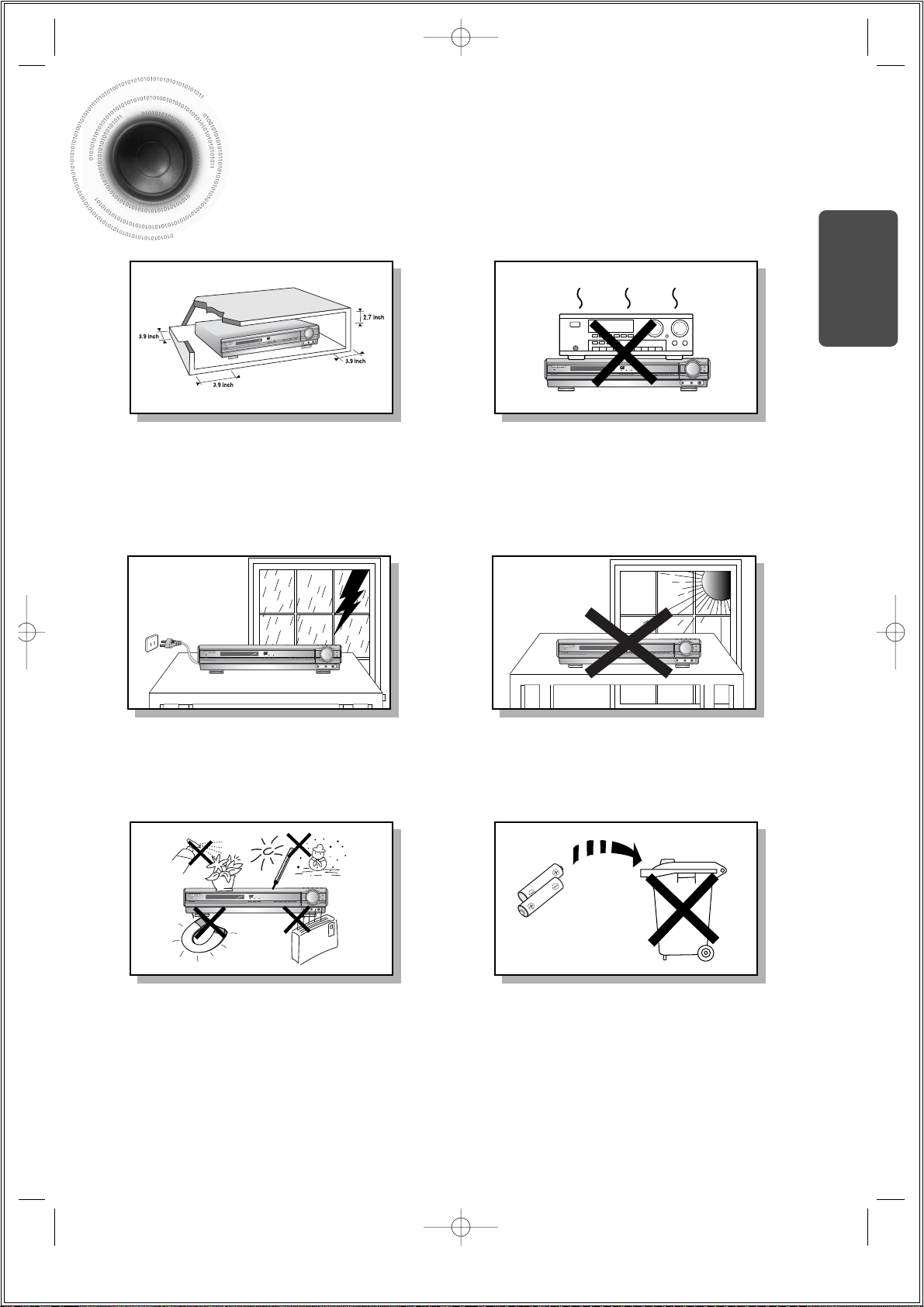
Ensure that the AC power supply in your house complies with the identification sticker located on the back of your player. Install your
player horizontally, on a suitable base (furniture), with enough space around it for ventilation (3~4inches). Make sure the ventilation slots
are not covered. Do not stack anything on top of the player. Do not place the player on amplifiers or other equipment which may become
hot. Before moving the player, ensure the disc tray is empty. This player is designed for continuous use. Switching off the DVD player to
the stand-by mode does not disconnect the electrical supply. In order to disconnect the player completely from the power supply,
remove the main plug from the wall outlet, especially when left unused for a long period of time.
Protect the player from moisture(i.e. vases) , and excess
heat(e.g.fireplace) or equipment creating strong magnetic or electric
fields (i.e.speakers...). Disconnect the power cable from the AC supply if
the player malfunctions. Your player is not intended for industrial use.
Use of this product is for personal use only.
Condensation may occur if your player or disc have been stored in cold
temperatures.
If transporting the player during the winter, wait approximately 2 hours
until the unit has reached room temperature before using.
During thunderstorms, disconnect AC main plug from the
wall outlet.
Voltage peaks due to lightning could damage the unit.
Do not expose the unit to direct sunlight or other heat
sources.
This could lead to overheating and malfunction of the unit.
The battery used with this product contain chemicals that
are harmful to the environment.
Do not dispose of batteries in the general household trash.
PREPARATION
1p~42p(DS690)-SEA 9/15/04 5:00 PM Page 5
Page 4
Safety Instructions
3
READ INSTRUCTIONS
All the safety and operating instructions should be
read before the appliance is operated.
RETAIN INSTRUCTIONS
The safety and operating instructions should be
retained for future reference.
HEED WARNINGS
All warnings on the appliance and in the operating
instructions should be adhered to.
FOLLOW INSTRUCTIONS
All operating and use instructions should be
followed.
WATER AND MOISTURE
Do not use this video product near waterforexample, near a bathtub, wash bowl,
kitchen sink, or laundry tub, in a wet basement,
or near a swimming pool, and the like.
OVERLOADING
Do not overload wall outlets and extension cords as
this can result in the risk of fire
or electric shock.
VENTILATION
Slots and openings in the cabinet are provided
for ventilation and to ensure reliable operation of the
video product and to protect it from overheating
these openings must not be blocked or covered.
The openings should never be blocked
by placing the video product on a bed, sofa, rug, or
other similar surface. This video product
should never be placed near or over a radiator or
heat register.
This video product should not be placed
in a built-in installation such as a bookcase
or rack unless proper ventilation is provided
or the manufacturer's instructions have been
followed.
POWER CORD PROTECTION
Power-supply cords should be routed so that
they are not likely to be walked on or pinched
by items placed upon or against them paying
particular attention to cords at plugs,
convenience receptacles, and the point where
they exit from the appliance.
CLEANING
Unplug this video product from the wall outlet
before cleaning. Do not use liquid cleaners
or aerosol cleaners. Use a damp cloth for cleaning.
LIGHTNING
For added protection of this video product
receiver during a lightning storm, or when
it is left unattended and unused for long
periods of time, unplug it from the wall outlet
and disconnect the antenna or cable system.
This will prevent damage to the video product
due to lightning and power-line surges.
OBJECT AND LIQUID ENTRY
Never push objects of any kind into this
product through openings as they may touch
dangerous voltage points or short-out parts
that could result in a fire or electric shock.
Never spill liquid of any kind on the video
product.
ACCESSORIES
Do not place this video product on an unstable cart,
stand, tripod, bracket, or table.
The video product may fall, causing serious injury to
a child or adult, and serious damage
to the appliance.
Use only with a cart, stand, tripod, bracket,
or table recommended by the manufacturer,
or sold with the video product. Any mounting
of the appliance should follow the manufacturer's
instructions and should use a mounting accessory
recommended by the manufacturer.
CART
An appliance and cart combination should be moved
with care. Quick stops, excessive force, and uneven
surfaces may cause the appliance and cart
combination to overturn.
POWER SOURCES
This video product should be operated only from the
type of power source indicated
on the marking label. If you are not sure
of the type of supply to your home, consult your
appliance dealer or local power company.
For video products intended to be operated from
battery power, or other sources, refer
to the operating instructions.
1p~42p(DS690)-SEA 9/15/04 5:00 PM Page 6
Page 5
4
POWER LINES
An outside antenna system should not be located in
the vicinity of overhead power lines or other electric
light or power circuits,
or where it can fall into such power lines
or circuits. When installing an outside antenna
system, extreme care should be taken to keep from
touching such power lines or circuits as contact with
them might be fatal.
POLARIZATION
This video product is equipped with a polarized
alternating current line plug (a plug having one blade
wider than the other.) This plug will fit into the power
outlet only one way.
This is a safety feature. If you are unable
to insert the plug fully into the outlet, try reversing
the
plug. If the plug should still fail to fit, contact your
electrician to replace your obsolete outlet. Do not
defeat the safety purpose of the polarized plug.
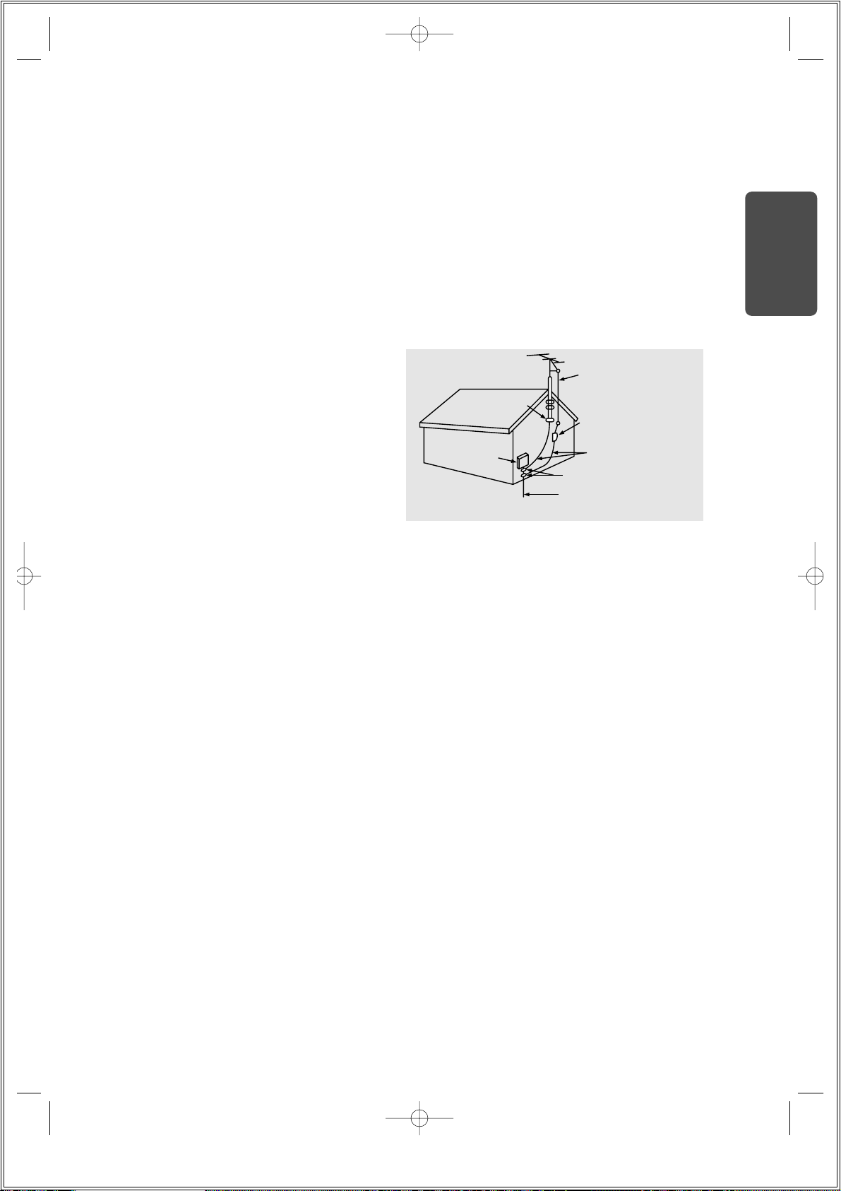
OUTDOOR ANTENNA GROUNDING
•
If an outside antenna is connected to the
antenna terminal, be sure the antenna system
is grounded so as to provide some protection
against voltage surges and built-up static
charges.
•
In the U.S.A section 810 of the National
Electrical Code, ANSI/NFPA No. 70-1984,
provides information with respect to proper
grounding of the mast and supporting
structure, grounding of the lead-in wire
to an antenna discharge unit, size of grounding
conductors location of antenna discharge unit,
connection to grounding electrodes, and
requirements for the grounding electrode.
See the figure below.
ATTACHMENTS
Do not use attachments not recommended
by the video product manufacturer as they may
cause hazards.
SERVICING
•
Do not attempt to service this product yourself
as opening or removing covers may expose
you to dangerous voltage or other hazards.
•
Refer all servicing to qualified service personnel.
REPLACEMENT PARTS
When replacement parts are required, be sure the
service technician has used replacement parts
specified by the manufacturer or having the same
characteristics as the original part. Unauthorized
substitutions may result in fire, electric shock or other
hazards.
SAFETY CHECK
Upon completion of any service or repairs
to this video product, ask the service technician to
perform safety checks to determine that the video
product is in proper operating condition.
DAMAGE REQUIRING SERVICE
Unplug this video product from the wall outlet
and
refer servicing to qualified service personnel
under the
following conditions.
a.
When the power-supply cord or plug is damaged.
b. If liquid has been spilled, or objects have
fallen into the video product.
c. If the video product has been exposed to rain
or water
d.
If the video product does not operate normally
by following the operating instructions.
Adjust only those controls that are covered
by the operating instructions as an improper
adjustment of other controls may result
in damage and will often require extensive
work by a qualified technician to restore
the video product to its normal operation.
e. If the video product has been dropped
or the cabinet has been damaged.
f. When the video product exhibits a distinct
change in performance - this indicates
a need for service.
HEAT
This video unit should be situated away from heat
sources such as radiators, stoves, or other products
(including amplifiers) that produce heat.
PREPARATION
1p~42p(DS690)-SEA 9/15/04 5:00 PM Page 7
ANTENNA
LEAD IN WIRE
ELECTRIC
SERVICE
EQUIPMENT
GROUND
CLAMP
ANTENNA
DISCHARGE UNIT
(NEC SECTION. 810-20)
GROUNDING CONDUCTORS
(NEC SECTION 810-21)
GROUND CLAMPS
POWER SERVICE GROUNDING
ELECTRODE SYSTEM
(NEC ART 250, PART H)
Page 6
Features
5
Multi-Disc Playback & AM/FM Tuner
The HT-DS690 combines the convenience of multi-disc playback capability, including DVDAUDIO, DVD-VIDEO, CD, MP3-CD, CD-R/RW, and DVD-R/RW, with a sophisticated AM/FM
tuner, all in a single player.
Super Digital Sound Master
Equipped with a new digital audio technology (Auto Sound Calibration, Magic
Sound Field, and Magic Headphone) developed in cooperation with DiMagic Co.,
Ltd. in Japan, you'll enjoy a more lively and sensitive sound.
Sound Logo
When power is turned on, a sound logo is output from the speakers to notify the user that the unit
is optimized for disc playback.
Power Saving Function
The HT-DS690 automatically shuts itself off after 20 minutes in the stop mode.
TV Screen Saver Function
The HT-DS690 automatically brightens and darkens the brightness of the TV screen after 3
minutes in the stop mode.
The HT-DS690 automatically switches itself into the power saving mode after 20 minutes in the
screen saver mode.
P.SCAN(Progressive Scan) Function
Unlike regular Interlace Scan, in which two fields of picture information alternate to create the
entire picture (odd scan lines, then even scan lines), Progressive Scan uses one field of
information (all lines displayed in one pass) to create a clear and detailed picture without visible
scan lines.
Customized TV Screen Display
The HT-DS690 allows you to select your favorite image during JPEG, DVD playback and set it as
your background wallpaper.
DVD-Audio compatible
Experience the super high-quality audio performance of DVD-Audio.
The on-board 24-bit/192kHz DAC enables this player to deliver exceptional sound quality in terms
of dynamic range, low-level resolution and high-frequency detail.
Wireless Rear Speakers and Amp
The HT-DS690 has a rear surround wireless amp that removes the need for long speaker cables
between the main unit and rear speakers.
Samsung AV Device Operation using Anynet
You can conveniently operate Samsung DVD and other Samsung AV devices with one remote
controller of Samsung TV, using Anynet.
1p~42p(DS690)-SEA 9/15/04 5:00 PM Page 8
Page 7
6
PREPARATION
Contents
PREPARATION
Safety Warnings..................................................................................................................................................................1
Precautions.........................................................................................................................................................................2
Safety Instructions ..............................................................................................................................................................3
Features..............................................................................................................................................................................5
Notes on Discs....................................................................................................................................................................7
Description..........................................................................................................................................................................9
CONNECTIONS
Connecting the Speakers....................................................................................................................................................13
Connecting the Video Out to TV.........................................................................................................................................17
P.SCAN(Progressive Scan) Function.................................................................................................................................18
Connecting External Components......................................................................................................................................19
How to Connect to Anynet..................................................................................................................................................21
Connecting the FM and AM Antennas................................................................................................................................22
Before Using Your DVD Player...........................................................................................................................................23
OPERATION
Disc Playback .....................................................................................................................................................................25
Selecting a Disc in the Disc changer ..................................................................................................................................26
MP3-CD Playback...............................................................................................................................................................27
JPEG Disc Playback...........................................................................................................................................................28
Displaying Disc Information ................................................................................................................................................29
Checking the Remaining Time............................................................................................................................................30
Fast/Slow Playback.............................................................................................................................................................31
Skipping Scenes/Songs......................................................................................................................................................32
Repeat Playback.................................................................................................................................................................33
A-B Repeat Playback..........................................................................................................................................................35
Angle Function....................................................................................................................................................................36
Zoom Function....................................................................................................................................................................37
Bonus Group / Navigating Pages........................................................................................................................................38
Selecting Audio/Subtitle Language.....................................................................................................................................39
Moving Directly to a Scene/Song........................................................................................................................................40
Using Disc Menu.................................................................................................................................................................41
Using the Title Menu...........................................................................................................................................................42
SETUP
Setting the Language..........................................................................................................................................................43
Setting TV Screen type.......................................................................................................................................................45
Setting Parental Controls (Rating Level).............................................................................................................................47
Setting the Password..........................................................................................................................................................49
Setting the Wallpaper..........................................................................................................................................................51
DVD Playback Mode...........................................................................................................................................................53
AV SYNC Setup..................................................................................................................................................................54
Setting the Speaker Mode ..................................................................................................................................................55
Setting the Test Tone..........................................................................................................................................................56
Setting the Delay Time........................................................................................................................................................57
Setting the Audio Quality ....................................................................................................................................................59
Setting the DRC (Dynamic Range Compression)...............................................................................................................61
Auto Sound Calibration Setup.............................................................................................................................................63
Live Surround Mode............................................................................................................................................................65
Dolby Pro Logic II Mode......................................................................................................................................................67
Dolby Pro Logic II Effect .....................................................................................................................................................68
RADIO OPERATION
Listening to Radio...............................................................................................................................................................69
Presetting Stations..............................................................................................................................................................70
MISCELLANEOUS
Convenient Functions.........................................................................................................................................................71
Operating a TV with the Remote Control............................................................................................................................73
Before Calling for Service...................................................................................................................................................75
Cautions on Handling and Storing Discs ............................................................................................................................77
Specifications......................................................................................................................................................................78
Notes on Terminology.........................................................................................................................................................79
Warranty .............................................................................................................................................................................80
1p~42p(DS690)-SEA 9/15/04 5:00 PM Page 9
Page 8
DVD (Digital Versatile Disc) offers fantastic audio and video, thanks to Dolby Digital
surround sound and MPEG-2 video compression technology. Now you can enjoy these
realistic effects in the home, as if you were in a movie theater or concert hall.
V I D E O
DVD players and the discs are coded by region. These regional codes must match in order
for the disc to play. If the codes do not match, the disc will not play.
The Region Number for this player is given on the rear panel of the player.
(Your DVD player will only play DVDs that are labeled with identical region codes.)
1 6
~
•
LD, CD-G, CD-I, CD-ROM and DVD-ROM cannot be played on this player.
If such discs are played, a "WRONG DISC FORMAT" message appears on the TV screen.
•
DVD discs purchased abroad may not play on this player.
If such discs are played, a "WRONG REGION CODE" message appears on the TV screen.
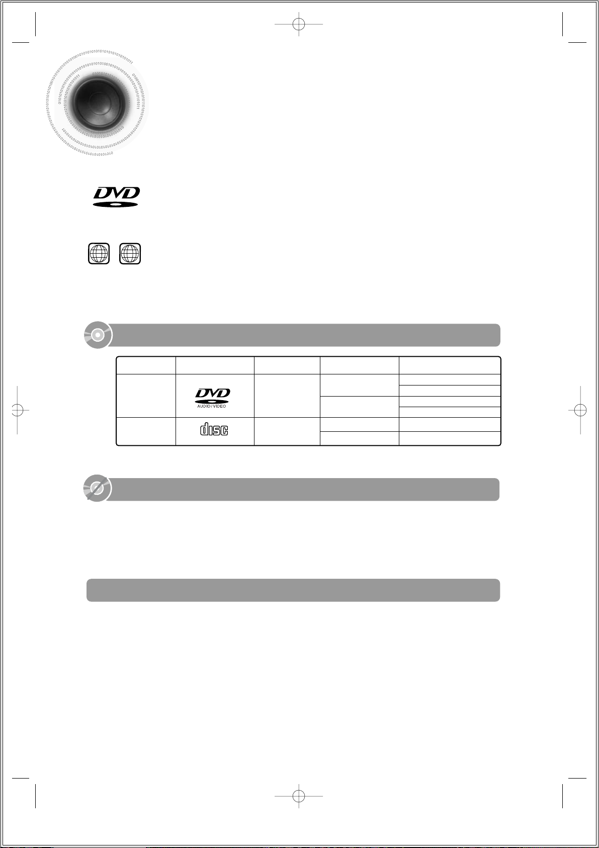
7
Notes on Discs
Do not use the following types of disc!
•
Many DVD discs are encoded with copy protection. Because of this, you should only connect your
DVD player directly to your TV, not to a VCR. Connecting to a VCR results in a distorted picture
from copy-protected DVD discs.
•
This product incorporates copyright protection technology that is protected by methods claims of certain
U.S. patents and other intellectual property rights owned by Macrovision Corporation and other rights
owners. Use of this copyright protection technology must be authorized by Macrovision Corporation, and
is intended for home and other limited viewing uses only unless otherwise authorized by Macrovision
Corporation. Reverse engineering or disassembly is prohibited.
Copy Protection
Mark (Logo)
Audio + Video
DVD-AUDIO
DVD-VIDEO
AUDIO-CD
5"
Approx. 240 min. (single-sided)
Approx. 480 min. (double-sided)
Approx. 80 min. (single-sided)
Approx. 160 min. (double-sided)
74 min.
20 min.
3 1/2"
5"
3 1/2"
Audio
Recorded Signals
Disc Type Disc Size Max. Playing Time
Playable Discs
1p~42p(DS690)-SEA 9/15/04 5:00 PM Page 10
COMPACT
DIGITAL AUDIO
Page 9

CD-R Discs
•
Depending on the disc recording device (CD-Recorder or PC ) and the condition of the disc, some CD-R discs
may not be playable.
•
Use a 650MB/74 minute CD-R. Avoid CD-R media, as they may not be playable.
•
If possible, do not use CD-RW (Rewritable) media, as they may not be playable.
•
Only CD-Rs that are properly "closed" can be fully played. If the session is closed but the disc is left open,
you may not be able to fully play the disc.
CD-R JPEG Discs
•
Only files with the ".jpeg" and ".JPEG" extensions can be played.
•
If the disc is not closed, it will take longer to start playing and not all of the recorded files may be played.
•
Only CD-R discs with JPEG files in ISO 9660 or Joliet format can be played.
•
JPEG file names should be 8 characters or less in length and contain no blank spaces or special characters (. / = +).
•
Only a consecutively written multisession disc can be played. If there is a blank segment in the multisession disc, the
disc can be played only up to the blank segment.
•
A maximum of 9,999 images can be stored on a single CD.
•
When playing a Kodak/Fuji Picture CD, only the JPEG files in the picture folder can be played.
•
Picture discs other than Kodak/Fuji Picture CDs may take longer to start playing or may not play at all.
Disc Recording Format
8
CD-R MP3 Discs
•
Only CD-R discs with MP3 files in ISO 9660 or Joliet format can be played.
•
MP3 file names should be 8 characters or less in length and contain no blank spaces or special characters (. / = +).
•
Use discs recorded with a compression/decompression data rate greater than 128Kbps.
•
Only files with the ".mp3" and ".MP3" extensions can be played.
•
Only a consecutively written Multisession disc can be played. If there is a blank segment in the Multisession disc, the
disc can be played only up to the blank segment.
•
If the disc is not closed, it will take longer to begin playback and not all of the recorded files may be played.
•
For files encoded in Variable Bit Rate (VBR) format, i.e. files encoded in both low bit rate and high bit rate (e.g.,
32Kbps ~ 320Kbps), the sound may skip during playback.
•
If more than 500 tracks are recorded on a single CD, a maximum of 500 tracks can be played.
•
If more than 300 folders are recorded on a single CD, a maximum of 300 folders can be played.
PREPARATION
1p~42p(DS690)-SEA 9/15/04 5:00 PM Page 11
Page 10
9
DIRECT PLAY
12 345
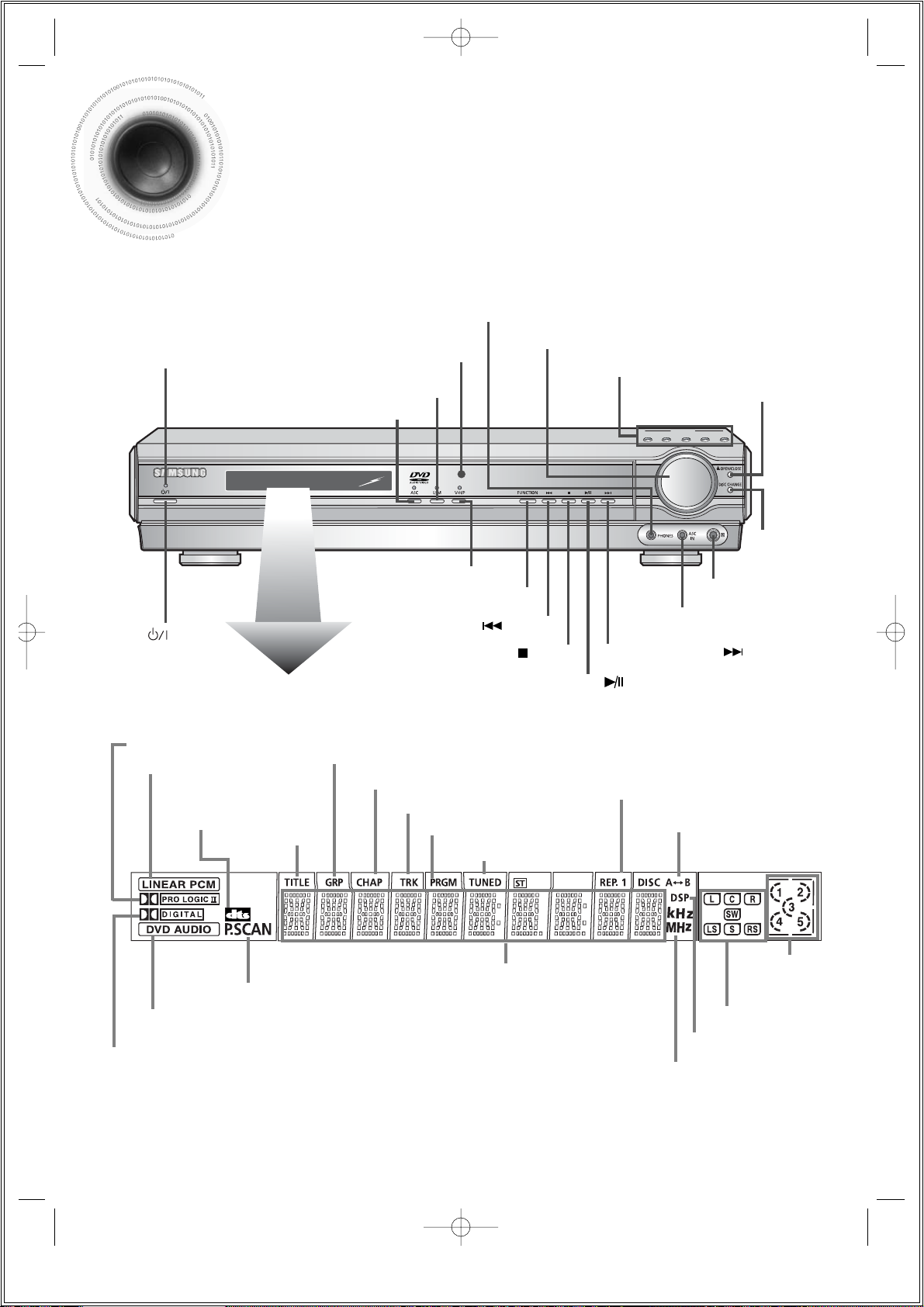
—Front Panel—
Description
Power ( ) button
Standby indicator
Function button
Virtual Headphone button
Headphone Jack
Disc Tray
Live Surround Mode button
Auto Sound Calibration button
Open/Close button
Direct Play button
Volume control
Disc Change
button
Auto Sound Calibration Input Jack
Remote Control Sensor
PRO LOGIC II indicator
LINEAR PCM indicator
DOLBY DIGITAL indicator
DVD AUDIO indicator
P.SCAN indicator
TITLE
indicator
GROUP indicator
REPEAT A↔ B indicator
PROGRAM indicator
CHAPTER indicator
DISC(1~5)
indicator
REPEAT indicator
TRACK indicator
TUNER indicator
DSP indicator
RADIO FREQUENCY
indicator
System Status Display
SPEAKER indicator
DTS Disc
indicator
Tuning Down & Skip ( ) buttons
Stop ( ) button
Play/Pause ( ) button
Tuning Up & Skip ( ) buttons
1p~42p(DS690)-SEA 9/15/04 5:00 PM Page 12
Page 11
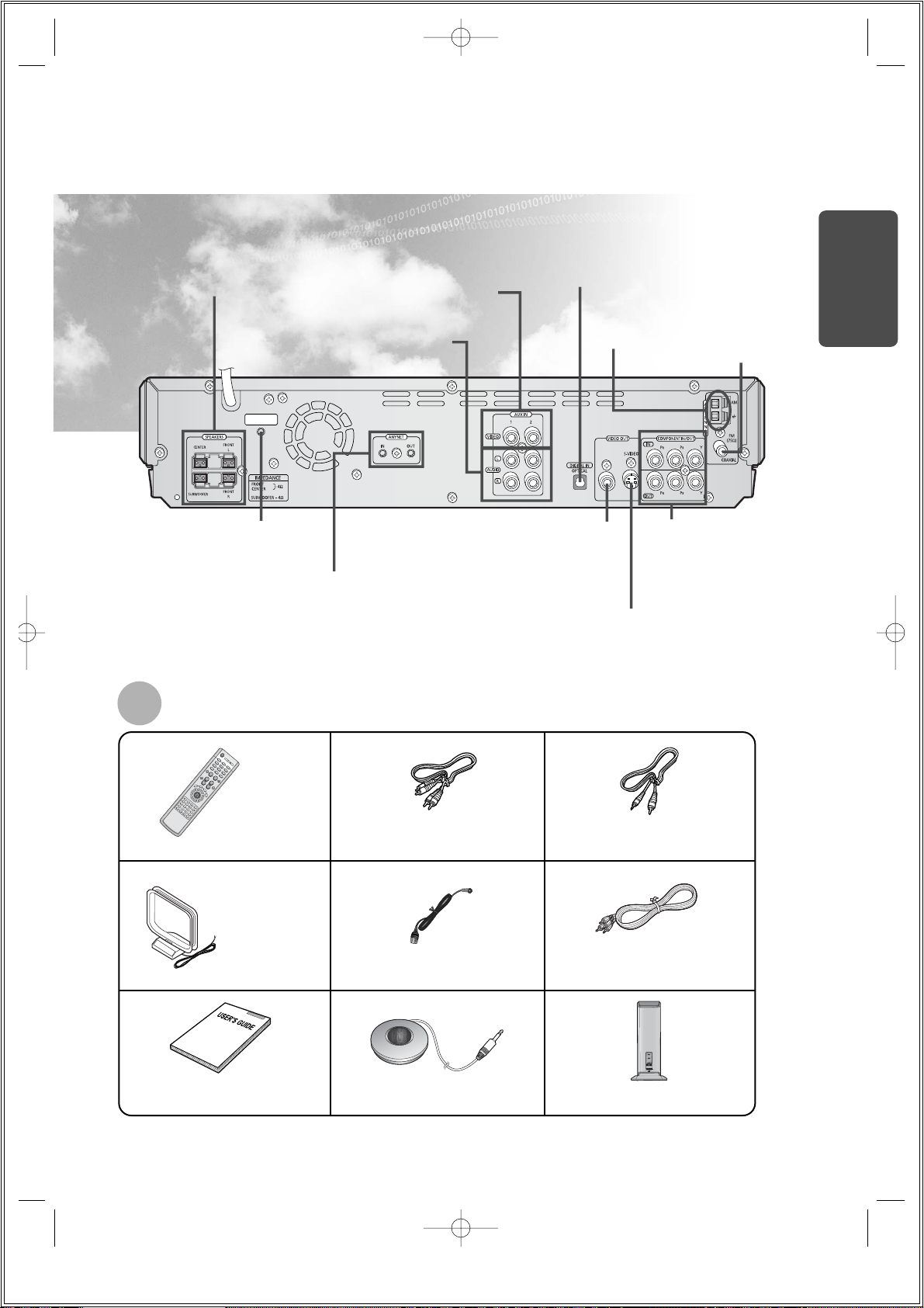
Audio Cable
(AH39-40001U)
Video Cable
(AH39-40001V)
Wireless rear receiver
Remote Control
(AH59-01329C)
FM Antenna
(AH42-00004A)
User's Manual
(AH68-01493G)
AM Antenna
(AH42-20001P)
Auto Sound Calibration Microphone
(AH59-01183D)
Anynet Cable
(AH39-40001Z)
10
Accessories
PREPARATION
* The wireless receiving antenna is built into the wireless rear amplifier.
REAR SPEAKER
ANTENNA
—Rear Panel—
AM Antenna
Connector
FM Antenna
Connector
External Video Component
Input Connectors
ANYNET
OUTPUT/INPUT
Connector
REAR SPEAKER ANTENNA
Connector
External Audio Component
Input Connector
Speaker Output
Terminals
COMPONENT VIDEO
OUTPUT/INPUT jacks
Connect a TV with component
video inputs to these jacks.
S-Video Output Connector
If the TV is equipped with an S-Video input
connector (S-VIDEO IN), connect it to the
player's S-Video output jack.
Video Output Connector
Connect the TV's video input jacks
(VIDEO IN) to the VIDEO OUT connector.
External Digital in Optical 1 Input
Connector
Use this to connect external equipment
capable of digital output.
1p~42p(DS690)-SEA 9/15/04 5:00 PM Page 13
Page 12
11
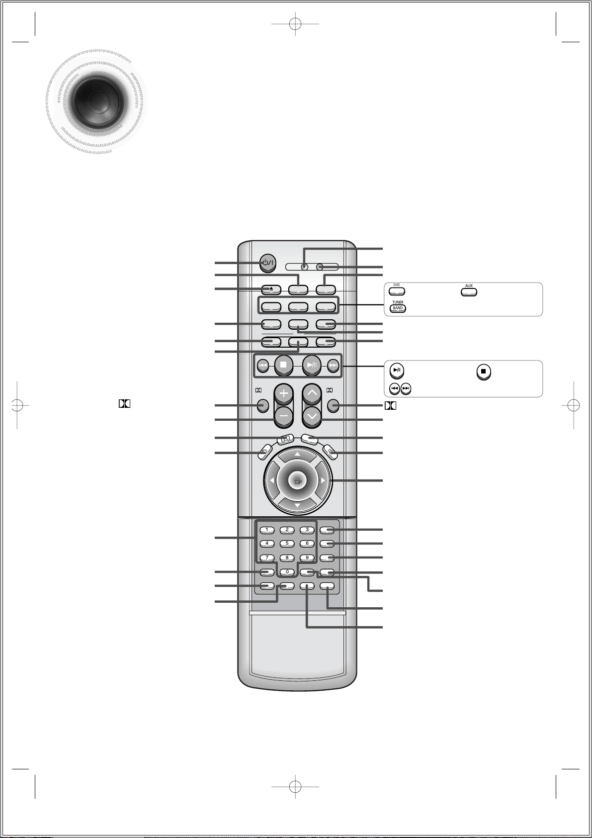
Description
TV DVD RECEIVER
OPEN/CLOSE
DVD TUNER AUX
EZ VIEW
SLOW DISC SKIP
ASC
TUNING/CH
PL II
R
E
T
U
R
N
M
EN
U
IN
F
O
MUTE
MODE
ENTER
SOUND EDIT
TEST TONE
SLEEP
LOGO REPEAT
CANCEL ZOOM
REMAIN
TUNER
MEMORY
P. SCAN
PL II
EFFECT
VOLUME
LSM
V-H/P
MOVIEMUSIC
SUPER5.1
BAND
MO/ST
TV/VIDEO MODE
DIMMER
PL II MODE button
VOLUME button
MENU button
TV, DVD POWER button
OPEN/CLOSE button
SUPER 5.1 button
Live Surround Mode button/
Virtual Headphone button
Auto Sound Calibration button
RETURN button
Number(0~9) buttons
SLEEP button
EZ VIEW button
LOGO COPY button
TV indicator
DVD RECEIVER indicator
TV/VIDEO, DIMMER button
MODE button
Direction/Enter button
REPEAT button
REMAIN button
CANCEL button
ZOOM button
TUNER MEMORY, P.SCAN button
SOUND EDIT button
TEST TONE button
MUTE button
INFO button
TUNING/CH button
MOVIE button
SLOW, MO/ST button
DISC SKIP button
PL II EFFECT button
—Remote Control—
DVD button
Play/Pause button
Tuning Preset/CD Skip button
Stop button
AUX button
TUNER BAND button
1p~42p(DS690)-SEA 9/15/04 5:00 PM Page 14
Page 13
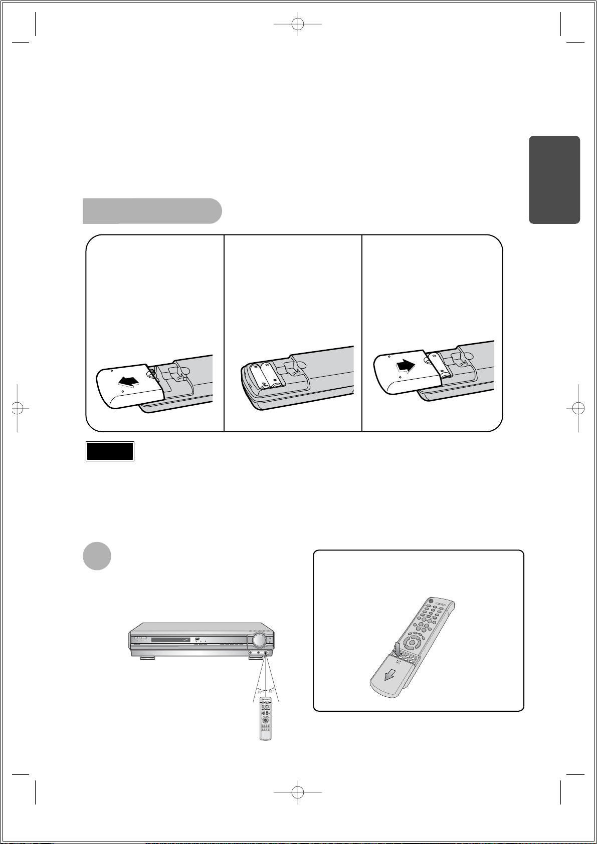
To open the remote control cover, push the
top of the cover, then slide downward.
12
Insert Remote Batteries
The remote control can be used up to approximately 23
feet/7 meters in a straight line. It can also be operated at
a horizontal angle of up to 30° from the remote control
sensor.
Range of Operation of the Remote Control
Remove the battery
cover on the back of
the remote by
pressing down and
sliding the cover in
the direction of the
arrow.
1
Insert two 1.5V AAA
batteries, paying
attention to the correct
polarities (+ and –).
2
Replace the battery
cover.
3
Follow these precautions to avoid leaking or cracking batteries:
•
Place batteries in the remote control so they match the polarity:(+) to (+)and (–)to (–).
•
Use the correct type of batteries.Batteries that look similar may differ in voltage.
•
Always replace both batteries at the same time.
•
Do not expose batteries to heat or flame.
Caution
PREPARATION
1p~42p(DS690)-SEA 9/15/04 5:00 PM Page 15
Page 14
RSLS
C
L
SW
R
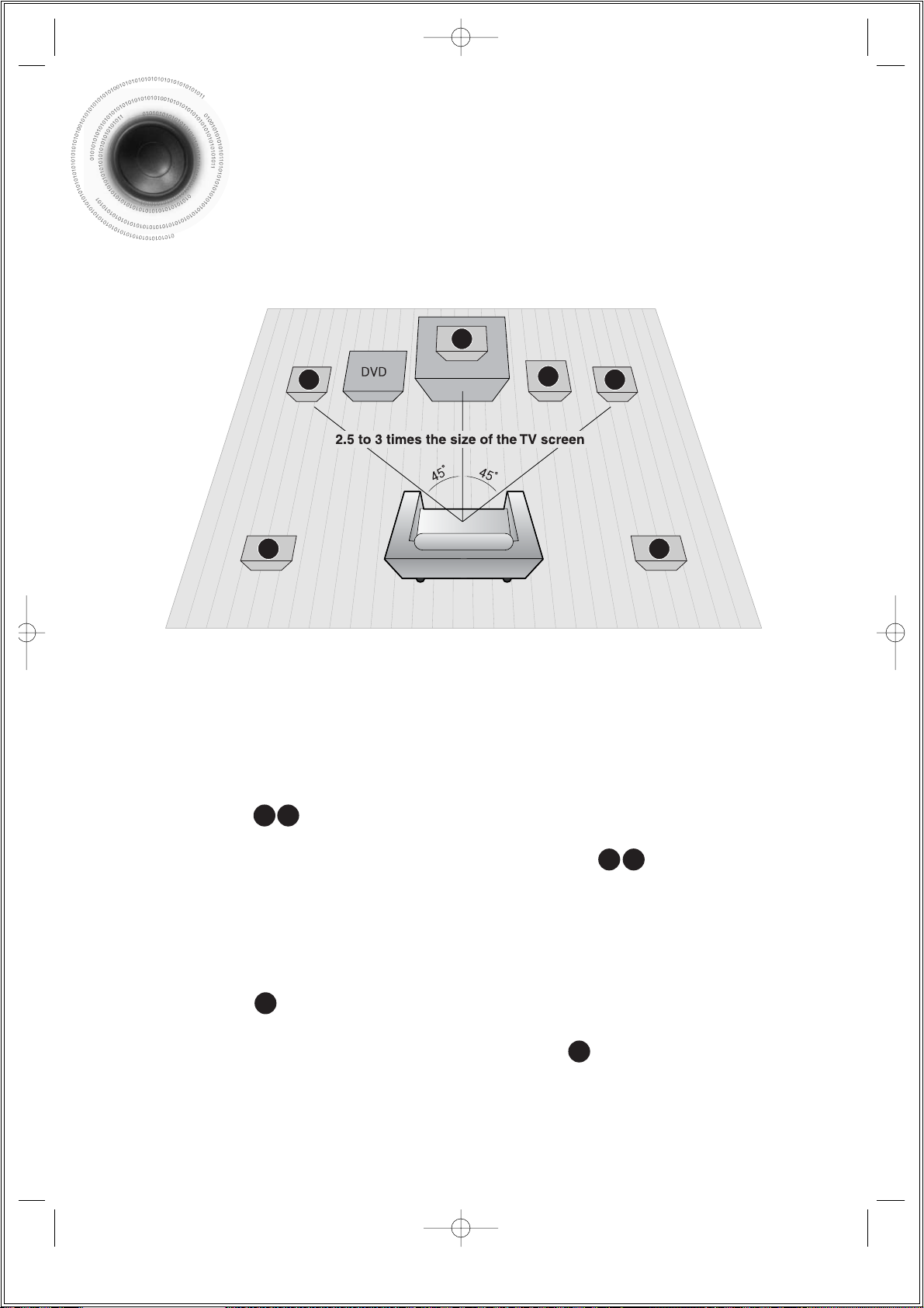
Rear Speakers
•
Place these speakers behind your listening position.
•
If there isn't enough room, place these speakers to face each other.
•
Place them about 60 to 90cm (2 to 3feet) above your ear, facing
slightly downward.
*
Unlike the front and center speakers, the rear speakers are used
to handle mainly sound effects and sound will not come from
them all the time.
Subwoofer
•
The position of the subwoofer is not so critical.
Place it anywhere you like.
•
Usually, it is placed by a corner near the front speakers.
Front Speakers
•
Place these speakers in front of your listening
position, facing inwards (about 45°) toward you.
•
Place the speakers so that their tweeters will be at
the same height as your ear.
•
Align the front face of the front speakers with the
front face of the center speaker or place them
slightly in front of the center speakers.
Center Speaker
•
It is best to install it at the same height as the front
speakers.
•
You can also install it directly over or under the TV.
Position of the DVD Player
•
Place it on a stand or cabinet shelf, or under
the TV stand.
Selecting the Listening Position
The listening position should be located about 2.5 to 3
times the distance of the TV's screen size away from the
TV. Example: For 32" TVs 2~2.4m (6~8feet)
For 55" TVs 3.5~4m (11~13feet)
13
Connecting the Speakers
Before moving or installing the product, be sure to turn off the power and disconnect the power cord.
R
L
C
RS
LS
SW
1p~42p(DS690)-SEA 9/15/04 5:00 PM Page 16
Page 15
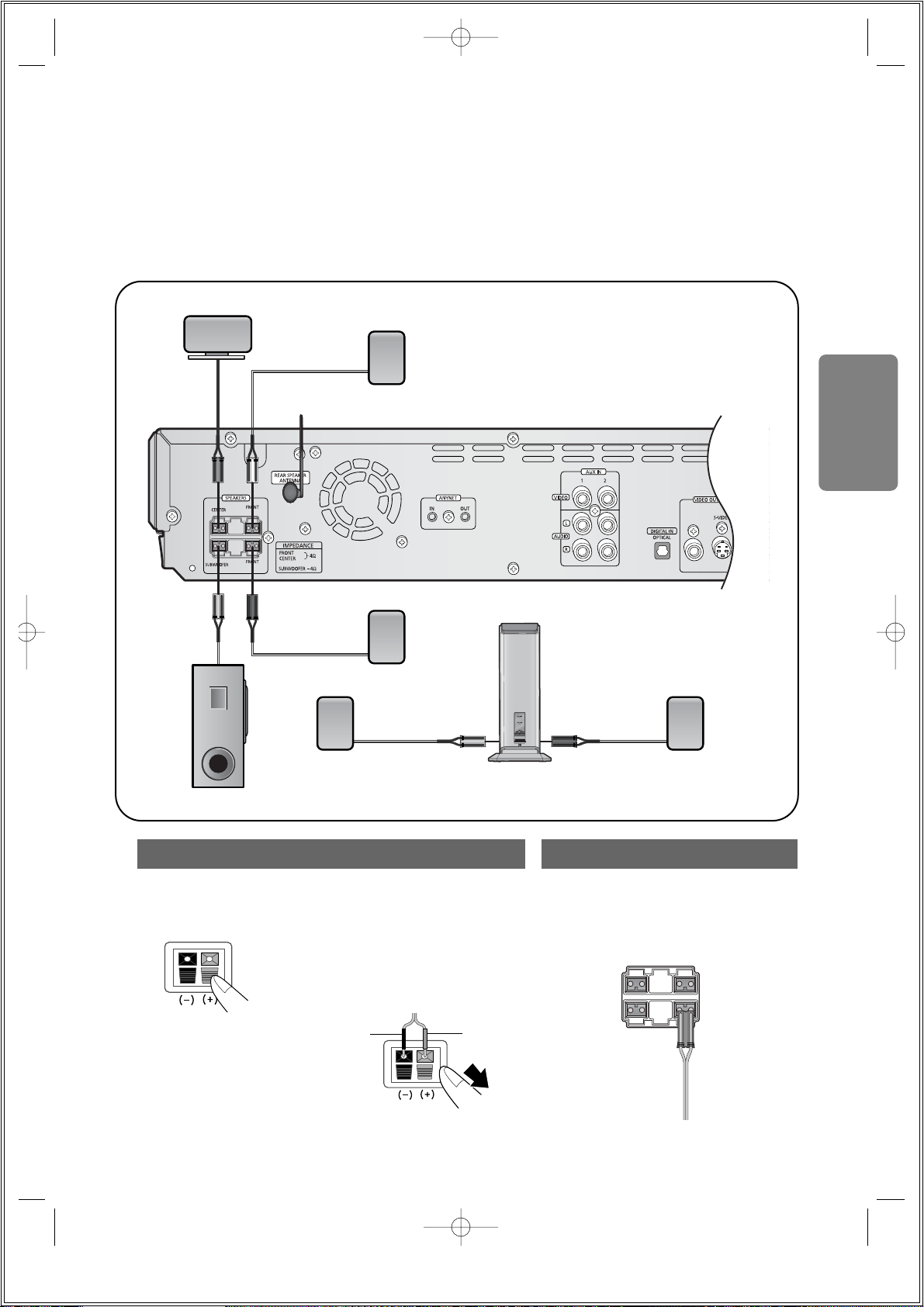
•
Make sure the colors of the speaker terminals
match the colors of the connecting plugs.
•
Insert the black wire into the black
(–) terminal and the gray wire into
the gray (+) terminal.
•
Make sure the polarities (+ and –)
are correct.
Black
Press down the terminal
tab on the back of the
speaker.
1
Insert the wire into the
terminal and release the
terminal tab.
2
Connect the connecting plugs to
the back of the DVD player.
3
Gray
14
Back of the Speakers Back of the Main Unit
CONNECTIONS
Wireless Rear
Speaker (L)
Wireless Rear
Speaker (R)
Wireless Rear Amplifier (SWA-1000)
(With built-in wireless receiving antenna)
Subwoofer
Center Speaker
REAR SPEAKER ANTENNA
Front Speaker (L)
Front Speaker (R)
Purple
Blue
White
Red
Gray
Green
1p~42p(DS690)-SEA 9/15/04 5:00 PM Page 17
Page 16
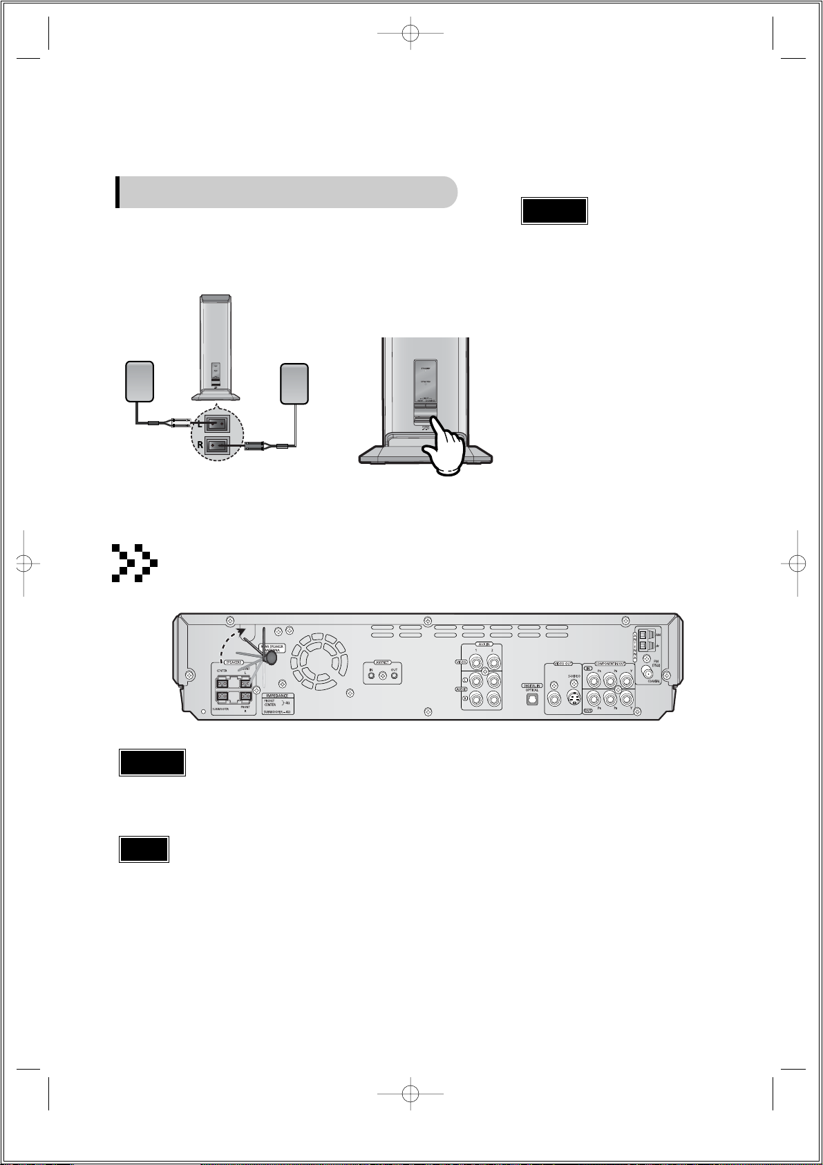
Connect your pair of
wireless rear speakers,
(L) and (R), to the
wireless rear amplifier.
1
Insert the power plug into an outlet,
and then press the POWER button
on the front panel.
•
The Power Standby indicator will light up.
•
To turn off the wireless rear amplifier,
press the POWER button in Standby mode.
2
•
Do not connect the wireless rear speakers
to the speaker outputs on the back of the
main unit. Malfunction may result.
•
The wireless receiving antenna is built into
the wireless rear amplifier.
Keep the unit away from water and
moisture.
•
For optimal listening performance, make
sure that the area around the proposed
wireless rear amplifier location is clear of
any obstructions.
Back of Wireless Rear Amplifier
Wireless Rear Speaker (R) Wireless Rear Speaker (L)
15
Caution
Connecting Wireless Rear Speakers
•
Do not apply a strong shock to the wireless transmission antenna. Breakage may result.
•
Do not touch the wireless transmission antenna during operation. Noise or interference to communications may result.
•
Place the wireless rear amplifier at the rear of the listening position. If the wireless rear amplifier is too close to the main unit, some sound
interruption may be heard due to interference.
•
If you use a device such as a microwave oven, wireless LAN Card, Bluetooth equipment, or any other device that uses the same frequency
(2.4GHz) near the system, some sound interruption may be heard due to interference.
•
The transmission distance of radio wave is about 33 feet but may vary depending on your operating environment. If a steel-concrete wall or
metallic wall is between the main unit and the wireless rear amplifier, the system may not operate at all because the radio wave cannot
penetrate metal.
Stand the wireless transmission antenna to face upward for best communication status.
Caution
Note
When using the wireless transmission antenna
1p~42p(DS690)-SEA 9/15/04 5:00 PM Page 18
Page 17
•
Sound will be heard from the wireless rear speakers in
DVD 5.1-CH or Dolby Pro Logic II mode only.
•
In 2-CH mode, no sound will be heard from the wireless
rear speakers.
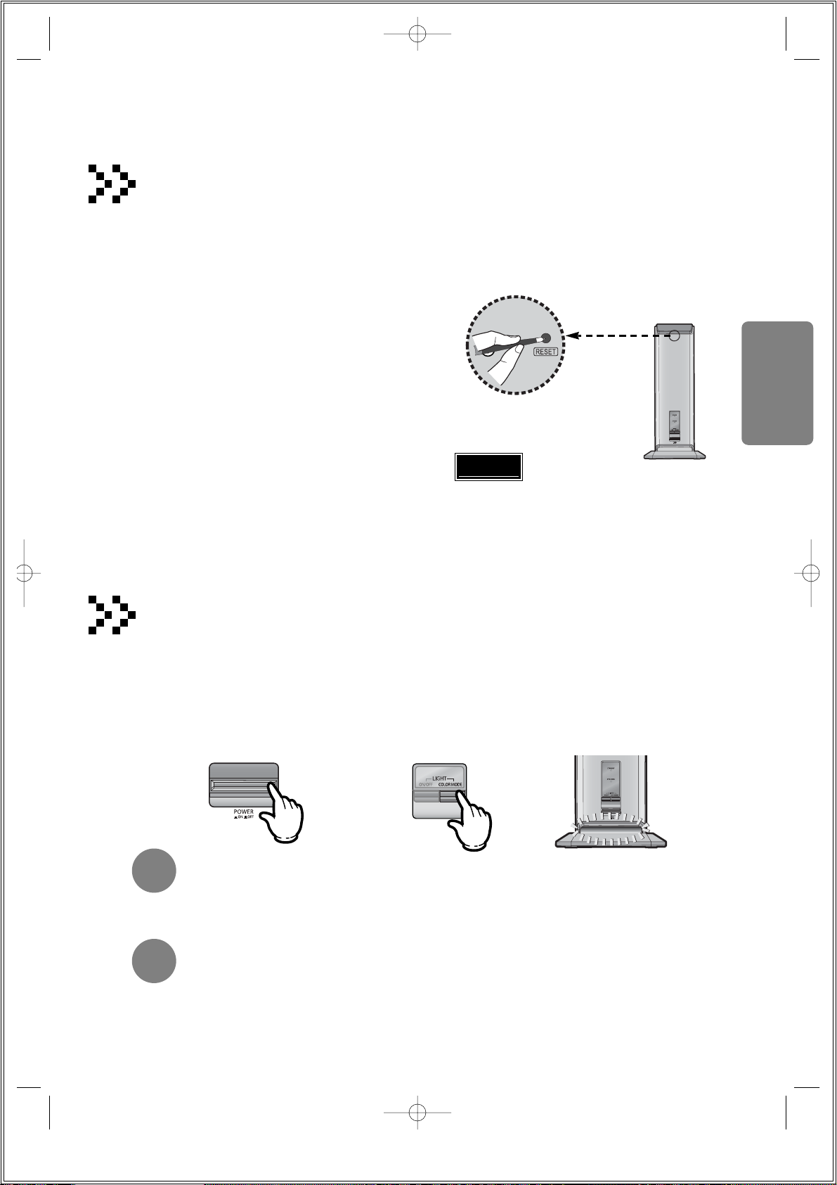
Reset the system if a communication failure occurs, or if the synchronizing signal indicator does not light
up and the "REAR CHK" message blinks on the main unit's display.
Reset the system while the main unit and the wireless rear amplifier (SWA-1000) are in Power Standby
mode.
Resetting Wireless Communication
With the main unit turned off, press and
hold the remote control's REMAIN button
for 4 seconds.
•
Press the button until the volume control indicator
lights up blue. (The indicator will turn off in 1 second.)
With the wireless rear amplifier turned
on, use a ball point pen or a pair of
tweezers to press the RESET button
on the back of the unit 2 to 3 times.
2
1
You can turn the mood light on the wireless rear amplifier on or off, as well as change the light to one of 7 different
colors according to your preference.
Turning On the Mood Light
Press the POWER on the
wireless amplifier.
•
The Power Standby indicator on the
wireless amp panel will light up and
the mood light will turn on.
1
Press the COLOR MODE button.
•
Each time the button is pressed, the color changes as
follows: Blue
➞ Light Green ➞ Red ➞ Sky Blue ➞
Yellow ➞ Pink ➞ White.
2
Turn on the main unit.
•
The wireless rear amplifier's synchronizing signal
indicator will light up.
•
If Power Standby mode continues, repeat Steps 1
to 3 above.
3
RESET Button
•
Press the POWER button on the wireless amp.
The wireless rear amplifier and the mood light will turn off.
When the wireless amp is powered on again, the mood light will be blue.
•
In Power Standby mode, press the ON/OFF button on the Wireless amp.
The mood light will light up or turn off with the last color selected.
Turning Off the Mood Light
Turning off the Wireless Amp and Mood Light
Back of Wireless Rear Amplifier
16
CONNECTIONS
Caution
1p~42p(DS690)-SEA 9/15/04 5:00 PM Page 19
Page 18
17
Connecting the Video Out to TV
Composite Video (Good Quality)
Connect the supplied video cable from the VIDEO OUT jack on the back panel of the
system to the VIDEO IN jack on your television.
S-Video (Better Quality)
If you television is equipped with an S-Video input, connect an S-Video cable (not supplied)
from the S-VIDEO OUT jack on the back panel of the system to the S-VIDEO IN jack on
your television.
Component Video (Best Quality)
If your television is equipped with Component Video inputs, connect a component video
cable (not supplied) from the Pr, Pb and Y jacks on the back panel of the system to the
corresponding jacks on your television.
Composite
Video
Component
Video
S-Video
TV
•
When the Progressive scan mode is selected, the VIDEO and S-VIDEO outputs do not feed
any signal. See page 18 to select Progressive Scan.
*
Depending on your TV, Component Video input jacks may be marked as DVD Video input.
Note
1p~42p(DS690)-SEA 9/15/04 5:00 PM Page 20
Page 19
18
CONNECTIONS
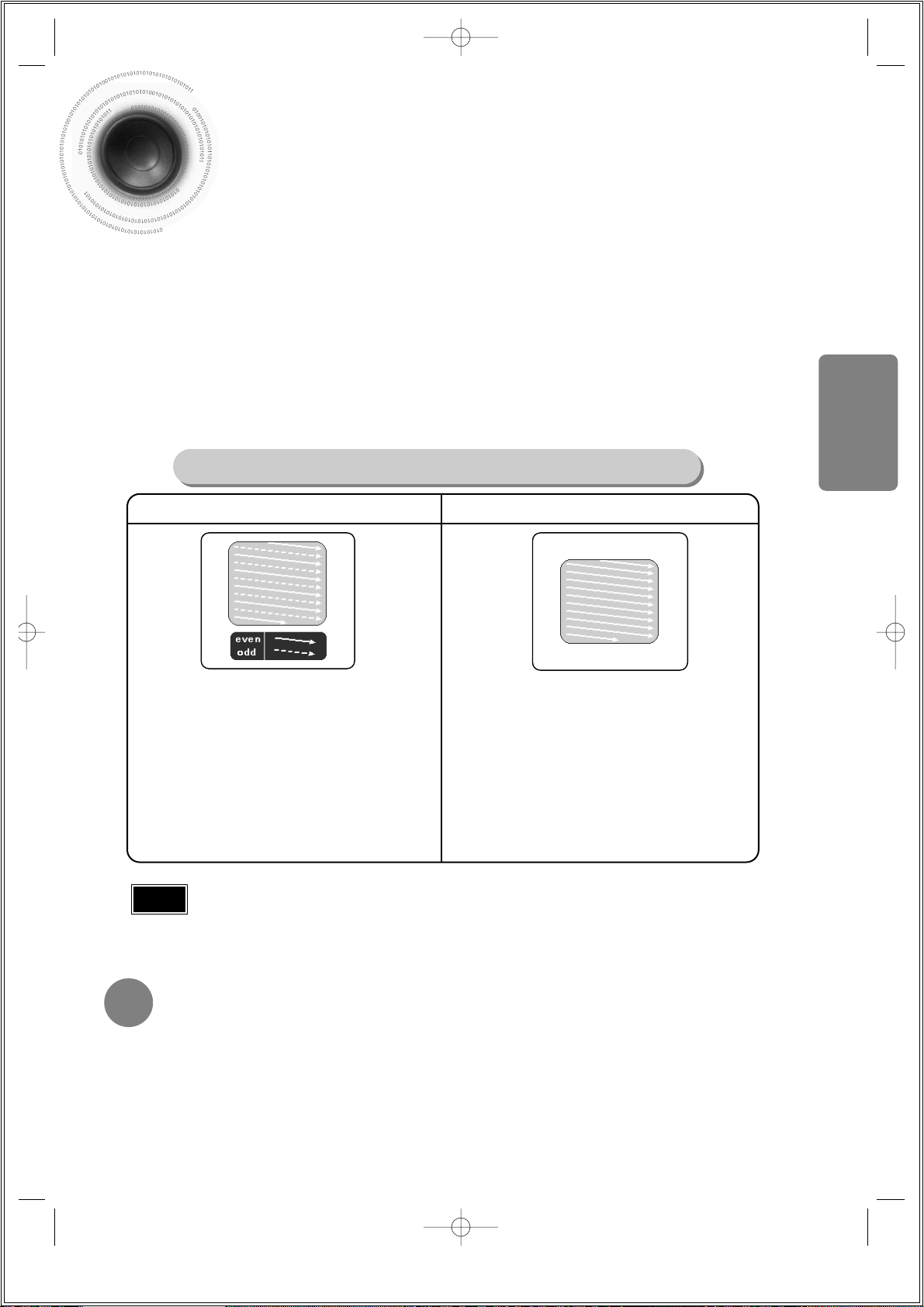
P.SCAN(Progressive Scan) Function
Unlike regular Interlace Scan, in which two fields of picture information alternate to create the
entire picture (odd scan lines, then even scan lines), Progressive Scan uses one field of
information (all lines displayed in one pass) to create a clear and detailed picture without visible
scan lines.
Press STOP button.
•
When disc is played back, press the STOP button twice so that “STOP”, appears on the display.
Press and hold P.SCAN button on the remote control for over 5 seconds.
•
Pressing and holding the button for over 5 seconds will select "Progressive Scan" and "Interlace Scan"
repetitively.
•
When you select P.SCAN, "P.SCAN" will appear on the display
In interlaced-scan video, a frame consists of two
interlaced fields (odd and even), where each field
contains every other horizontal line in the frame.
The odd field of alternating lines is displayed first, and
then the even field is displayed to fill in the alternating
gaps left by the odd field to form a single frame.
One frame, displayed every 1/30th of a second, contains
two interfaced fields, thus a total of 60 fields are
displayed every 1/60th of a second.
The interlaced scanning method is intended for capturing
a still object.
Interlaced Scan (1 FRAME = 2 FIELDS)
The progressive scanning method scans one full frame of
video consecutively down the screen, line by line.
An entire image is drawn at one time, as opposed to the
interlaced scanning process by which a video image is
drawn in a series of passes.
The progressive scanning method is desirable for dealing
with moving objects.
Progressive Scan (FULL FRAME)
What is Progressive (or Non-Interlaced) Scanning?
•
This function works only on TVs equipped with component video inputs (Y, Pr, Pb) that support
Progressive Video. (It does not work on TVs with conventional component inputs, i.e., non-progressive
scan TVs.)
•
Depending on the brand and model of your TV, this function may not work.
Note
Press and hold NTSC/PAL button on the remote controller for over 5 seconds while the power is turned off.
•
"NTSC" or "PAL" will appear in the display.
At this time, press the NTSC/PAL button shortly to select between "NTSC" and "PAL".
•
Each country has a different video format standard.
•
For normal playback, the video format of the disc must be the same as the video format of your TV.
Selecting the Video Format
1
2
1p~42p(DS690)-SEA 9/15/04 5:00 PM Page 21
Page 20
Press AUX on the remote control to select ‘DIGITAL IN’.
•
Each time the button is pressed, the selection changes as follows: DIGITAL IN ➝ AUX 1 ➝ AUX 2.
•
You can also use the FUNCTION button on the main unit.
The mode switches as follows: DVD/CD ➝ DIGITAL IN ➝ AUX1 ➝ AUX2 ➝ FM ➝ AM.
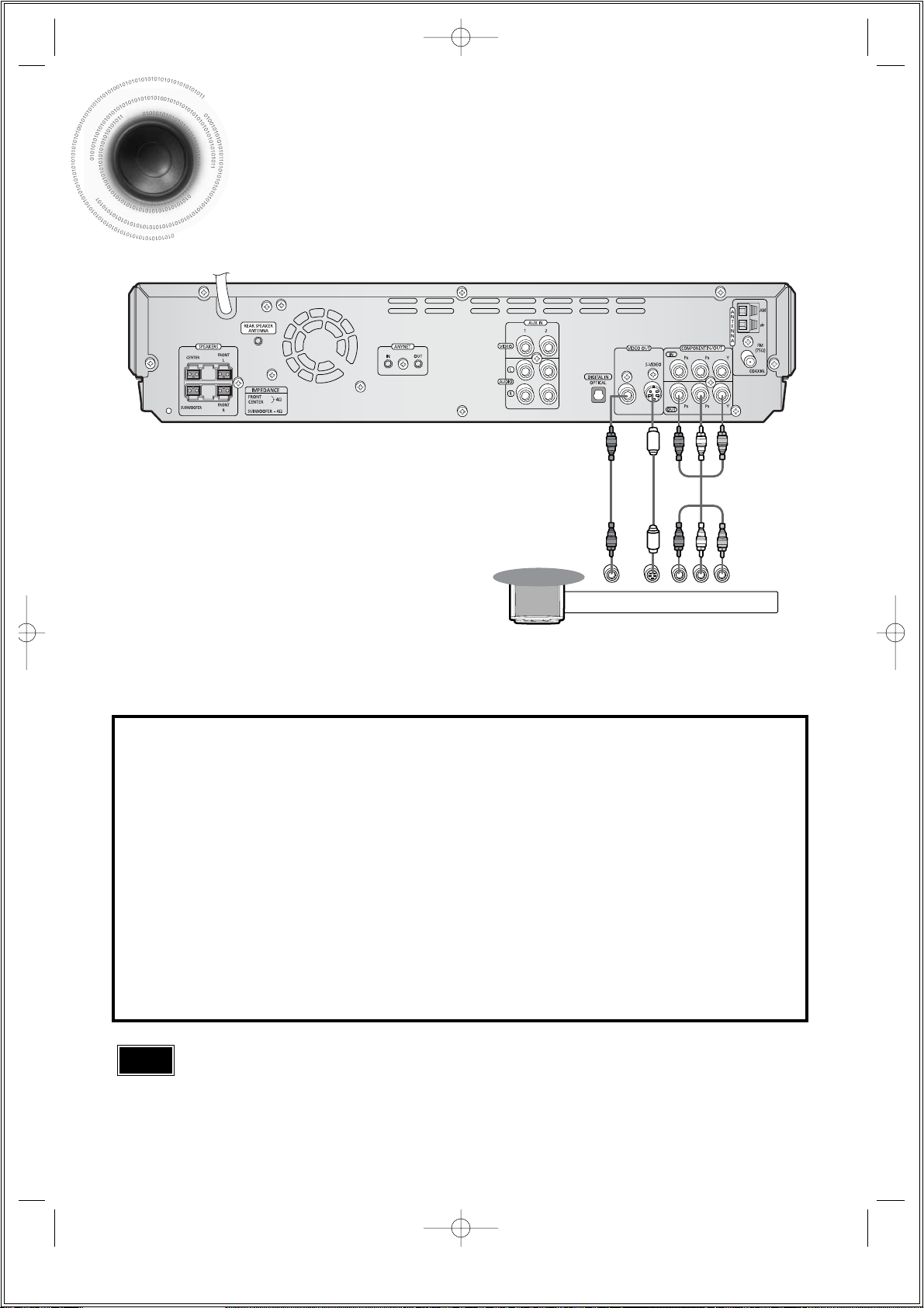
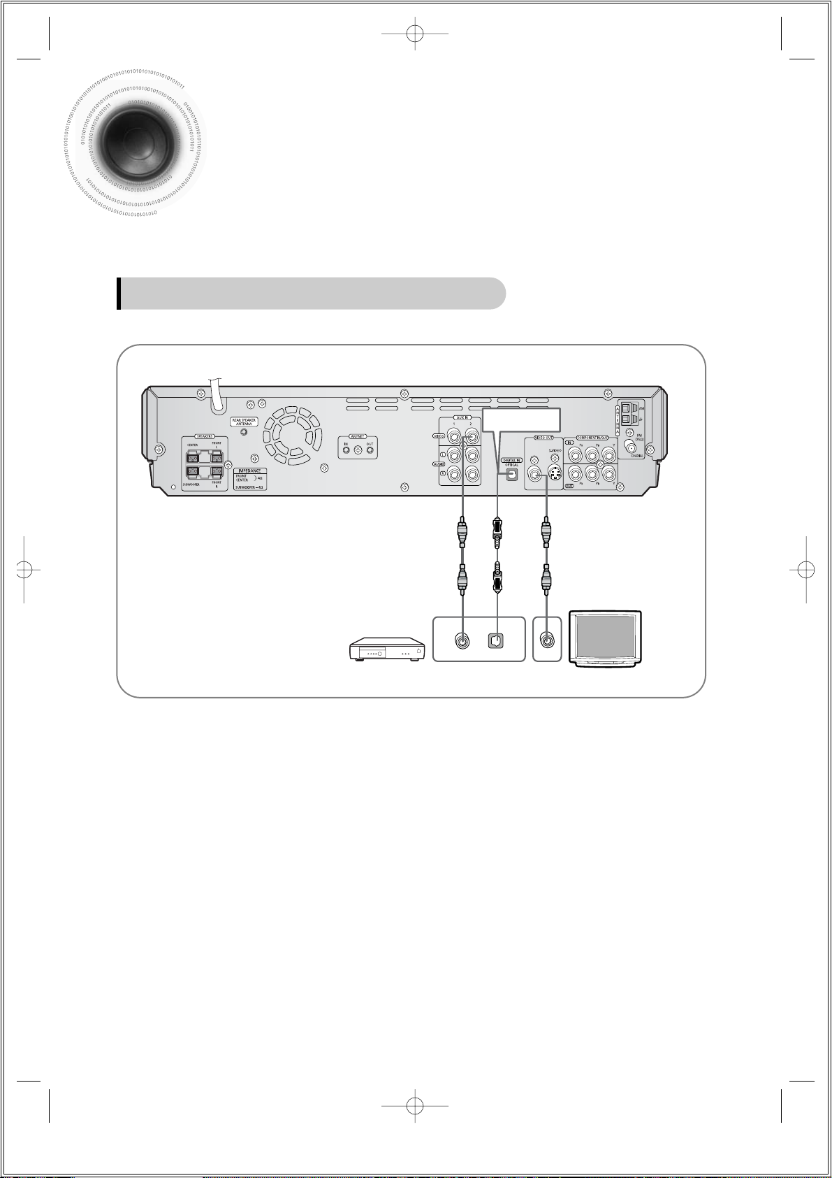
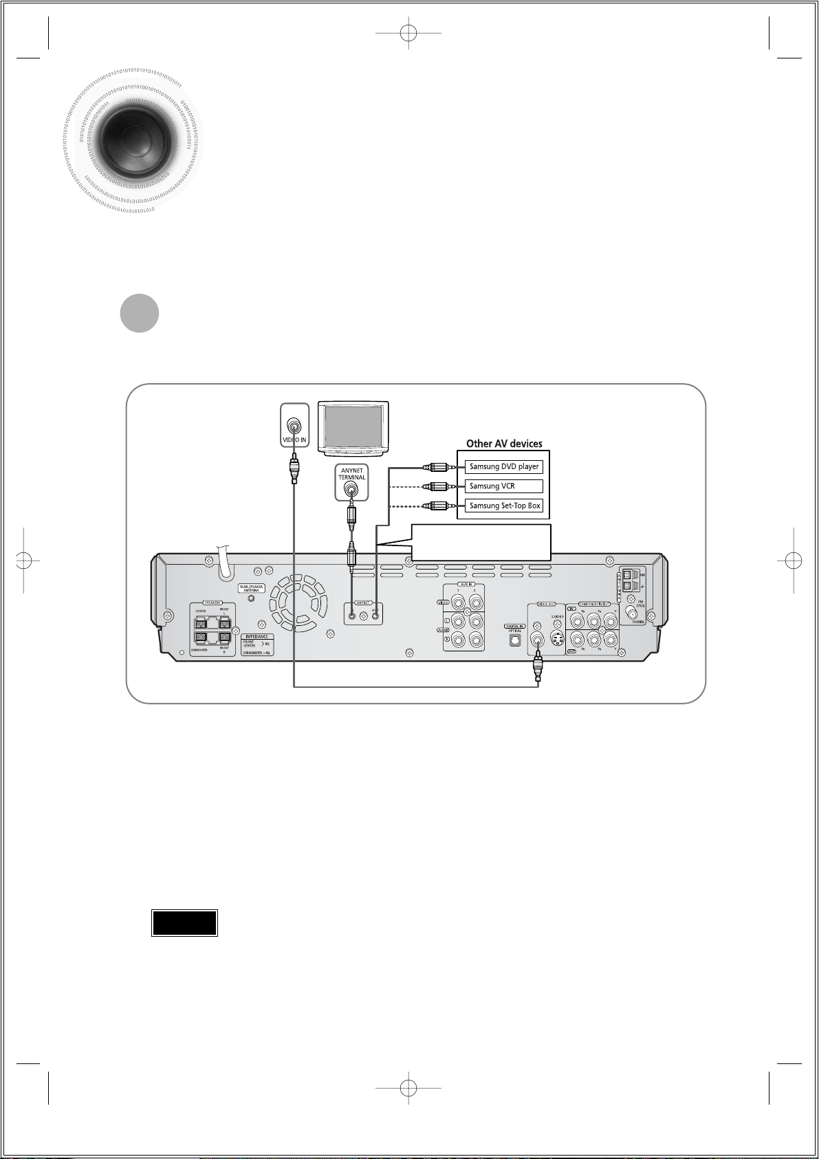
Connecting External Components
Connect Video Out on the DVD player to Video In on the TV.
1
Connect the Digital Input (OPTICAL) to the Digital Output on the external digital component.
2
3
19
Example: Digital signal components such as a Settop Box or CD Recorder.
Connecting an External Digital Component
Optical Cable
(not included)
1p~42p(DS690)-SEA 9/15/04 5:00 PM Page 22
DIGITAL OUTVIDEO OUT
VIDEO IN
Page 21
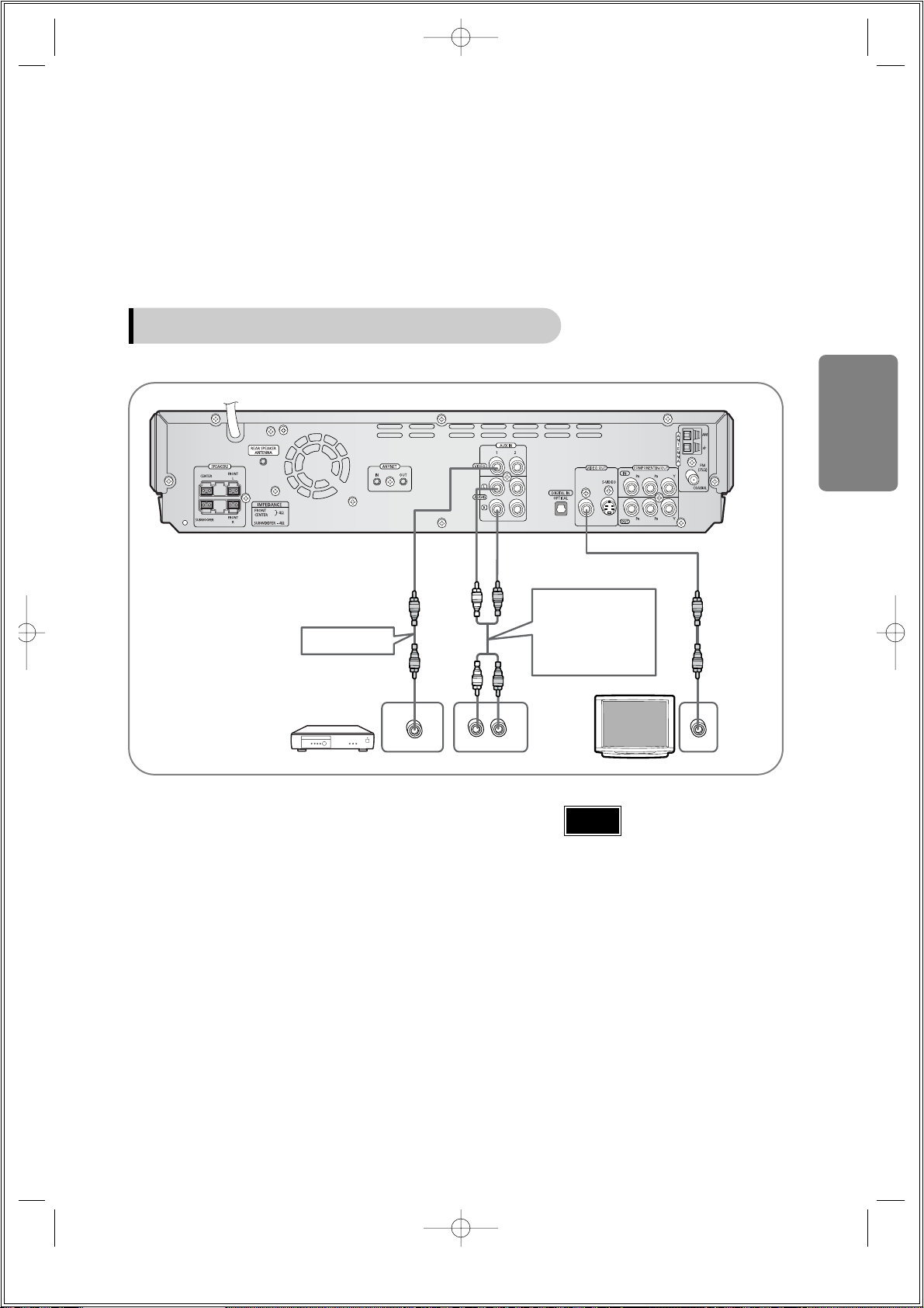
Press AUX on the remote control to select AUX 1 or
AUX 2.
•
Each time the button is pressed, the selection changes as
follows: DIGITAL IN ➝ AUX 1 ➝ AUX 2.
•
You can also use the FUNCTION button on the main unit.
The mode switches as follows: DVD/CD ➝ DIGITAL IN ➝
AUX1 ➝ AUX2 ➝ FM ➝ AM.
•
If you have connected an external digital
component and also an Analog
component to Video In (1, 2) at the same
time, there will be video from AUX 1 even
when you select DIGITAL IN.
•
If you have connected Audio In (L, R) to
1, connect Video In to 1 as well, and if
you have connected Audio In (L, R) to 2,
connect Video In to 2 also.
•
When you select Aux 1 or 2, you are
selecting Video 1 or 2 inputs respectively.
Connect Audio In on the DVD player to Audio
Out on the external analog component.
•
Be sure to match connector colors.
Connect Video Out on the DVD player to Video
In on the TV.
1
Connect Video In on the DVD player to Video
Out on the external analog component.
2
3
4
20
Example: Analog signal components such as a VCR or TV.
Connecting an External Analog Component
Video Cable
Audio Cable
If the external analog
component has only
one Audio Out,
connect either left or
right.
Note
CONNECTIONS
1p~42p(DS690)-SEA 9/15/04 5:00 PM Page 23
L
VIDEO OUT AUDIO OUT
R
VIDEO IN
Page 22
21
Connect the Anynet input terminal on the back of this unit to your Samsung TV's Anynet
output terminal.
1
Connect the Anynet Out Terminal on the back of this unit to the Anynet input of Samsung
external AV devices.
2
Use this to connect Anynet-enabled
AV devices when necessary.
How to Connect to Anynet
Using the Anynet function, the DVD Home Theater System can be conveniently controlled from
your Samsung TV. By connecting the Anynet output terminal on the DVD Home Theater
System to the input terminal of any Samsung Anynet-enabled device, both can be controlled
from your TV. For detailed operation instructions and connection diagram, refer to the user's
manual of your Anynet-enabled TV.
What is Anynet?
•
The Anynet function allows you to use your TV's remote control and menu to control all AV devices.
•
However, this function is available only with Samsung Anynet-enabled models.
Refer to the user's manual of your Anynet-enabled TV and activate the Anynet function.
3
*
This function is available only with Anynet-enabled TVs.
•
If the Anynet input and output terminals are reversed, communication with the TV will fail and
you will not be able to use the Anynet function.
Caution
1p~42p(DS690)-SEA 9/15/04 5:00 PM Page 24
Page 23
22
CONNECTIONS
The cooling fan dissipates the heat generated inside the unit so that the unit can be operated
normally. The cooling fan is activated automatically to supply cool air to the unit.
Please observe the following cautions for your safety.
•
Make sure the unit is well-ventilated. If the unit has poor ventilation, the temperature inside the unit could rise
and may damage it.
•
Do not obstruct the cooling fan or ventilation holes. (If the cooling fan or ventilation holes are covered with a
newspaper or cloth, heat may build up inside the unit and fire may result.)
Cooling Fan
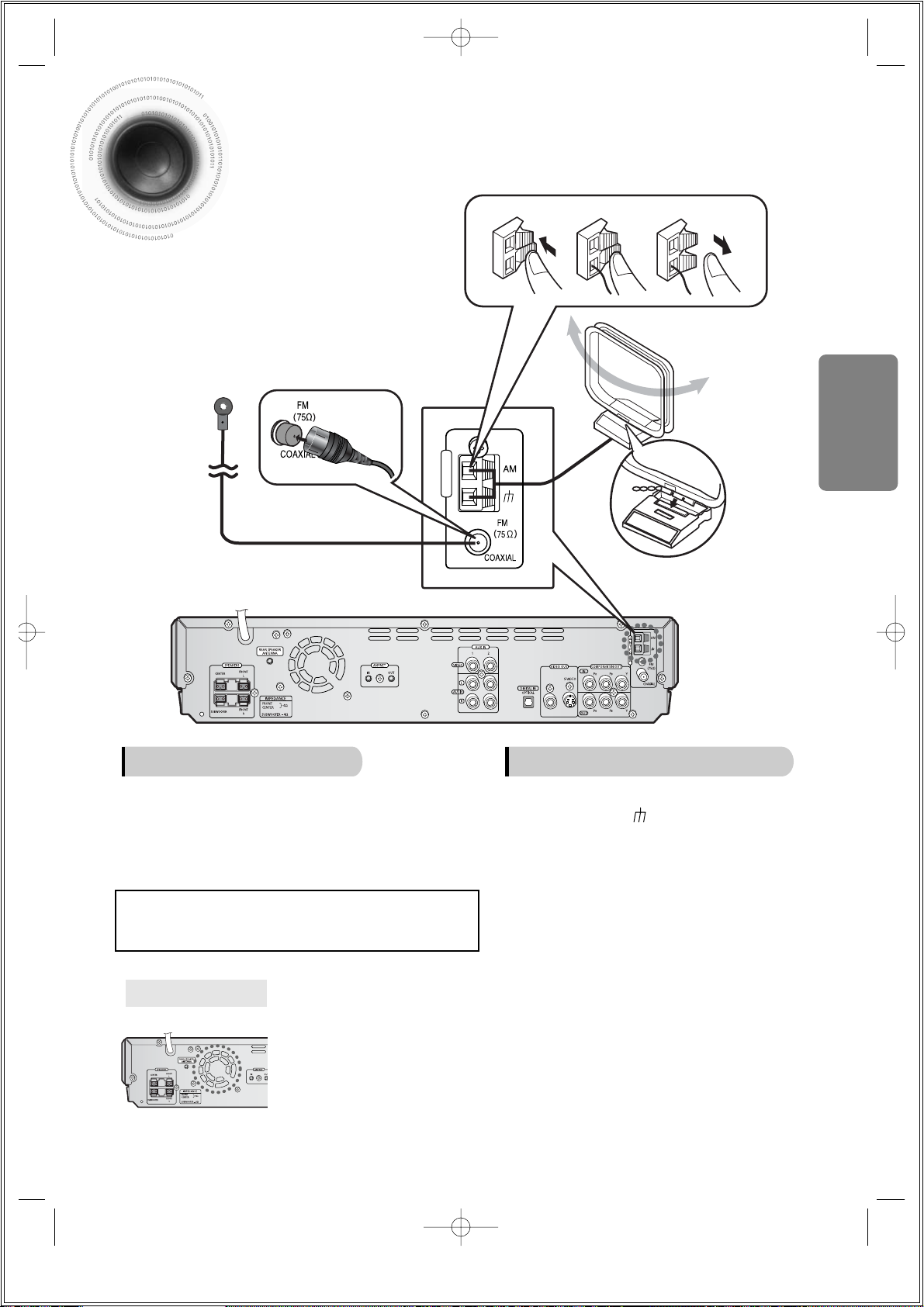
Connecting the FM and AM Antennas
FM antenna connection AM antenna connection
1. Connect the FM antenna supplied to the FM 75Ω
COAXIAL terminal as a temporary measure.
2. Slowly move the antenna wire around until you
find a location where reception is good, then
fasten it to a wall or other rigid surface.
•
If reception is poor, connect an outdoor antenna.
Before attaching a 75Ω coaxial cable (with a standard
type connector), disconnect the supplied FM antenna.
1. Connect the AM loop antenna supplied
to the AM and terminals.
2. If reception is poor, connect an outdoor
single vinyl-covered wire to the AM
terminal. (Keep the AM loop antenna
connected).
Snap the tabs on the loop into the
slots of the base to assemble the
AM loop antenna.
A
N
T
E
N
N
A
123
FM Antenna (supplied)
AM Loop Antenna
(supplied)
If AM reception is poor, connect an
outdoor AM antenna(not supplied).
1p~42p(DS690)-SEA 9/15/04 5:00 PM Page 25
Page 24
•
Each time the button is pressed, the TV indicator (red) and the DVD Receiver indicator (green) will flash
alternately.
•
You can operate the TV while the TV indicator is flashing and the DVD player while the DVD indicator is flashing.
•
Buttons Enabled for TV Operation: POWER, CHANNEL, VOLUME, TV/VIDEO, and Numeric (0-9) buttons.
•
By default, the remote control is set to work with Samsung TVs. See page 65 for more information on the
operation of the remote control.
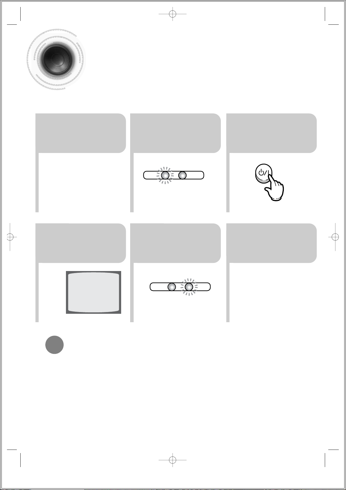
Press MODE button.
To Operate the TV and DVD Player with a Single Remote Control
23
Press the MODE
button so that the TV
indicator on the
remote control flashes.
TV
DVD RECEIVER
TV
DVD RECEIVER
Press the POWER
button to turn on
the TV.
56
Press the MODE button so
that the DVD RECEIVER
indicator on the remote
control flashes.
Press DVD button
to select DVD/CD
mode.
23
Before Using Your DVD Player
Your DVD player is capable of playing DVD, CD, MP3 and JPEG discs.Depending on the disc you
are using, these instructions may vary slightly. Read the instructions carefully before using.
1
Plug the power
cord into the AC
power supply.
4
Press TV/VIDEO
button to select
VIDEO mode.
1p~42p(DS690)-SEA 9/15/04 5:00 PM Page 26
Page 25
24
CONNECTIONS
•
In this manual, the instructions marked with "DVD ( )" are applicable to
DVD-VIDEO, DVD-AUDIO, and DVD-R/RW discs.
Where a particular DVD type is mentioned, it is indicated separately.
•
Depending on the content of the disc, the initial screen may appear different.
DVD
Note
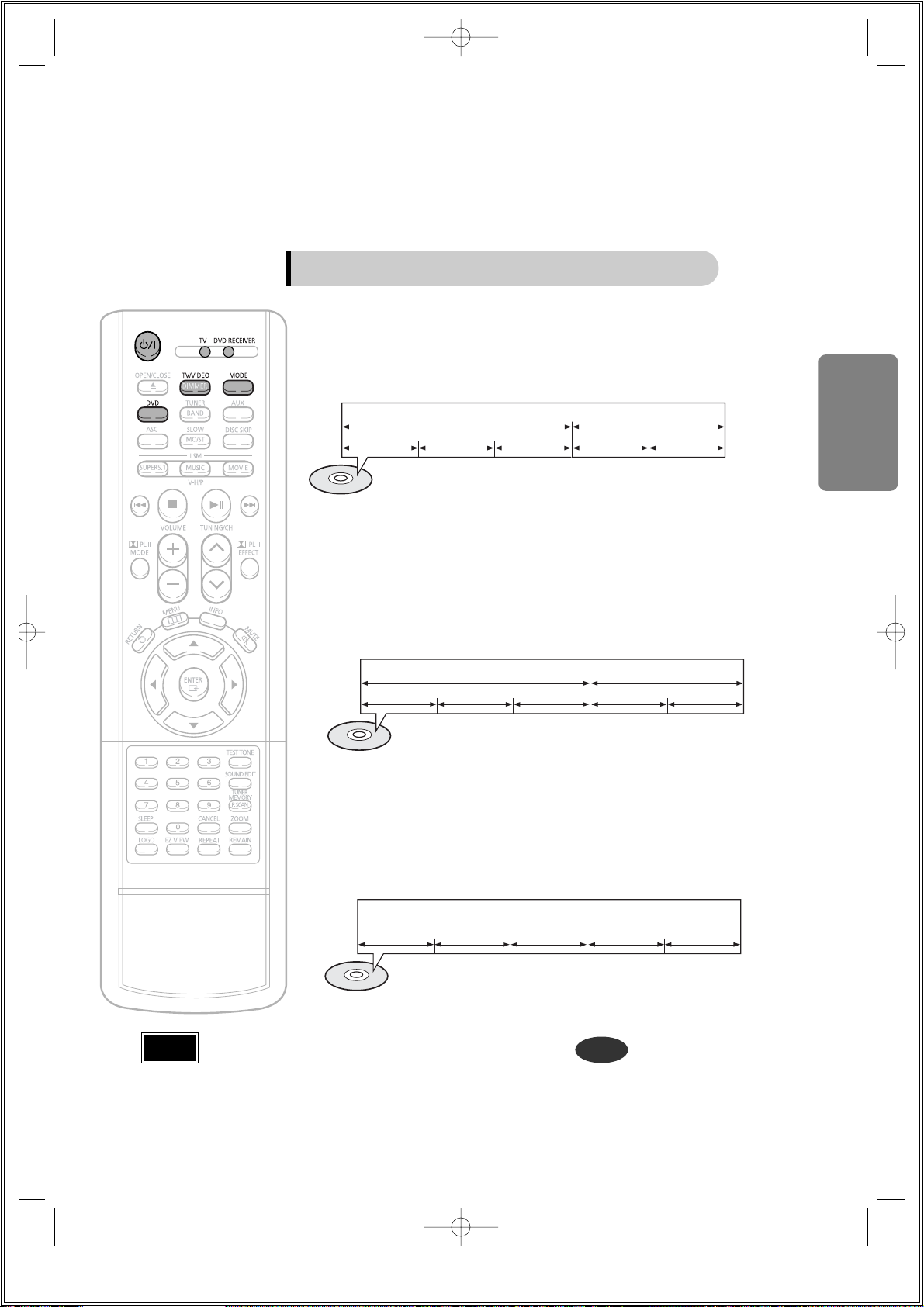
Groups and tracks (DVD-AUDIO)
•
DVD-audio is divided into several large sections called "groups" and smaller
sections called "tracks". Numbers are allotted to these sections.
These numbers are called "group numbers" and "track numbers".
GROUP 1 GROUP 2
TRACK 1 TRACK 2 TRACK 1 TRACK 2TRACK 3
Titles and chapters (DVD-VIDEO)
•
DVD-video is divided into several large sections called "titles" and smaller
sections called "chapters". Numbers are allotted to these sections.
These numbers are called "title numbers" and "chapter numbers".
TITLE 1 TITLE 2
CHAPTER 1 CHAPTER 2 CHAPTER 1 CHAPTER 2CHAPTER 3
Tracks (Video and music CDs)
•
Video and music CDs are divided into sections called "tracks".
Numbers are allotted to these sections. These numbers are called "track
numbers".
TRACK 1 TRACK 2 TRACK 4 TRACK 5TRACK 3
Disc terminology
1p~42p(DS690)-SEA 9/15/04 5:00 PM Page 27
Page 26

25
Disc Playback
2
1
Press OPEN/CLOSE button to open the
disc tray.
3
Press DISC SKIP button.
•
Rotate the carousel tray so you can load the third, fourth, and
fifth discs .
4
Close the compartment by pressing the
OPEN/CLOSE button again.
DVD CD
•
Playback starts automatically.
Load one or more discs.
•
Place a disc gently into the tray with the disc’s label
facing up.
•
To resume playback, press PLAY/PAUSE ( )
button again.
To temporarily pause playback,
press PLAY/PAUSE during playback.
•
If pressed once, “PRESS PLAY” is displayed and the
stop position will be stored in memory.
If PLAY/PAUSE ( ) button or ENTER button is
pressed, playback resumes from the stop position.
(This function works only with DVDs.)
•
If pressed twice, “STOP” is displayed, and if
PLAY/PAUSE ( ) button is pressed, playback
starts from the beginning.
To stop playback,
press STOP during playback.
1p~42p(DS690)-SEA 9/15/04 5:00 PM Page 28
Page 27

26
CONNECTIONS
.
Selecting a Disc in the Disc changer
To select a specific disc, press the corresponding DIRECT PLAY
(1, 2, 3, 4, 5) buttons on the front panel or DISC SKIP on the
remote control, until the required disc indicator flashes.
The DVD/CD function is automatically selected when Disc Skip is pushed.
If you wish to play the current disc only, press REPEAT on the remote control
one or more times, until REPEAT : DISC is displayed.
If the disc selected is not loaded, the next disc is played automatically.
•
All the discs will be played in turn, starting with the one selected.
1p~42p(DS690)-SEA 9/15/04 5:00 PM Page 29
Page 28

27
•
Depending on the recording mode, some MP3-CDs may not play.
•
Table of contents of a MP3-CD varies depending on the MP3 track format
recorded on the disc.
Note
MP3-CD Playback
Data CDs (CD-R, CD-RW) encoded in MP3 format can be played.
2
In Stop mode, use
to select
the album, and
then press the
ENTER button.
•
The MP3 menu screen will appear
and playback will start.
•
Depending on the MP3 disc, the
appearance of the menu may be
different.
1
Press the
OPEN/CLOSE
button to open the
disc tray, and then
load the MP3 disc.
4
Press the STOP
button to stop
playback.
•
To select another album and track,
repeat Steps 2 and 3 above.
3
To change the album,
use to
select another album
in Stop mode, and
then press the
ENTER button.
1p~42p(DS690)-SEA 9/15/04 5:00 PM Page 30
Page 29

28
JPEG Disc Playback
Images captured with a digital camera or camcorder, or JPG files on a PC can be stored on a CD and then
played back with this unit.
OPERATION
Press the OPEN/CLOSE button to open the disc tray, and then
load the JPEG disc.
•
Playback will start automatically and each image will show for 5 seconds before moving to
the next image.
Rotate vertically Rotate 90° counterclockwise
Rotate horizontally Rotate 90° clockwise
During playback, press .
To rotate the image
1p~42p(DS690)-SEA 9/15/04 5:00 PM Page 31
Page 30

Displaying Disc Information
You can view disc playback information on the TV screen.
Press INFO button.
•
Each time the button is pressed, the display changes as follows:
DVD
Display disappears
Display disappears Display disappears
MP3 JPEG
•
What is a Group?
A group of tracks contained in a DVD-AUDIO disc.
•
What is a Title?
A movie contained in a DVD-VIDEO disc.
•
What is a Chapter?
Each title on a DVD disc is divided into several smaller sections called "chapters".
•
What is a Track (File)?
A section of video or a music file recorded on a DVD-AUDIO, CD, or MP3-CD.
•
appears on the TV screen!
If this symbol appears on the TV screen while buttons are being operated, that
operation is not possible with the disc currently being played.
•
Depending on the disc, the disc
information display may appear different.
•
Depending on the disc, you can also
select DTS, DOLBY DIGITAL, or PRO
LOGIC.
29
Note
CD
Screen Display
DVD display
CD display
MP3 CD display
DVD-AUDIO display
TITLE display
GROUP display
CHAPTER display
TRACK (FILE) display
ELAPSED TIME display
AUDIO LANGUAGE display
SUBTITLE display
ANGLE display
STEREO (L/R) display
DOLBY DIGITAL display
REPEAT PLAYBACK display
DVD
AUDIO
1p~42p(DS690)-SEA 9/15/04 5:00 PM Page 32
DVD RECEIVER SMART NAVI
Something like you
Back for good
Love of my life
More than words
Page 31

30
OPERATION
Checking the Remaining Time
CHAPTER REMAIN
TITLE REMAIN
CHAPTER ELAPSED
TITLE ELAPSED
Each time the REMAIN button is pressed
Press the REMAIN button.
•
For checking the total and remaining time of a title or chapter
being played.
DVD-
VIDEO
TRACK REMAIN
GROUP REMAIN
TRACK ELAPSED
GROUP ELAPSED
DVD-
AUDIO
CD
TRACK REMAIN
TOTAL ELAPSED
TOTAL REMAIN
TRACK ELAPSED
MP3
TRACK ELAPSED
TRACK REMAIN
1p~42p(DS690)-SEA 9/15/04 5:00 PM Page 33
Page 32

Fast/Slow Playback
Fast Playback
DVD CD MP3
Press and hold .
•
Each time the button is held down during playback,
the playback speed changes as follows:
Press SLOW button.
•
Each time the button is pressed during playback,
the playback speed changes as follows:
Slow Playback
DVD
31
1p~42p(DS690)-SEA 9/15/04 5:00 PM Page 34
Page 33

Skipping Scenes/Songs
32
DVD MP3
DVD MP3
Briefly press .
•
Each time the button is pressed briefly during playback, the previous or next chapter, track,
or directory (file) will be played.
•
You cannot skip chapters consecutively.
•
During fast playback of a CD or MP3-CD, sound is heard only at 2x speed,
and not at 4x, 8x, and 32x speeds.
•
No sound is heard during slow playback and step motion playback.
TITLE 01/05 CHAPTER 002/040
TITLE 01/05 CHAPTER 004/040
Note
OPERATION
Something like you
Back for good
Love of my life
More than words
I need you
My love
Uptown girl
DVD RECEIVER SMART NAVI
Something like you
Back for good
Love of my life
More than words
I need you
My love
Uptown girl
DVD RECEIVER SMART NAVI
Something like you
Back for good
Love of my life
More than words
I need you
My love
Uptown girl
DVD RECEIVER SMART NAVI
1p~42p(DS690)-SEA 9/15/04 5:00 PM Page 35
Page 34

Repeat Playback
Repeat playback allows you to repeatedly play a chapter, title, track (song), or directory (MP3 file).
33
Press REPEAT button.
•
Each time the button is pressed during playback, the repeat playback
mode changes as follows:
CDMP3 JPEG
DVD CD MP3 JPEG
DVD-
VIDEO
DVD-
AUDIO
1p~42p(DS690)-SEA 9/15/04 5:00 PM Page 36
Page 35

34
• CHAPTER : Repeatedly plays the selected chapter.
• TITLE : Repeatedly plays the selected title.
• GROUP : Repeatedly plays the selected group.
• RANDOM : Plays tracks in random order.
(A track that has already been played may be played again.)
• TRACK : Repeatedly plays the selected track.
• DIR : Repeatedly plays all tracks in the selected folder.
• DISC : Repeatedly plays the entire disc.
• OFF : Cancels Repeat Playback.
OPERATION
To Select a Repeat Playback Mode in the Disc Information Screen
Press INFO button twice.
1
Press Cursor button to move to
REPEAT PLAYBACK( ) display.
2
Press Cursor button to select the
desired Repeat Playback mode.
3
DVD
CD
*
For MP3 and JPEG discs, you cannot select
Repeat Play from the information display screen.
Press ENTER button.
4
Repeat Playback Options
1p~42p(DS690)-SEA 9/15/04 5:00 PM Page 37
Page 36

A-B Repeat Playback
•
The A-B Repeat function will not work on an MP3 or JPEG disc.
2
Press Cursor
button to move to
REPEAT PLAYBACK
( ) display.
•
For a CD, press INFO button once.
1
Press INFO button
twice.
A -
A -?
REPEAT : A—
A - B
REPEAT : A—B
•
The specified segment will be played
repeatedly.
4
Press ENTER
button at the end
of the segment.
•
When ENTER button is pressed,
the selected position will be stored in
memory.
3
Press Cursor ,
buttons to select ‘A-’ and then
press ENTER button at the
beginning of the segment.
To return to normal playback, press Cursor ,
buttons to select OFF.
DVD CD
Note
35
1p~42p(DS690)-SEA 9/15/04 5:00 PM Page 38
Page 37

Angle Function
This function allows you to view the same scene in different angles.
DVD
2
Press Cursor
button to move to
ANGLE
( )
display.
1
Press INFO button.
1/3
•
Each time the button is pressed, the angle changes as follows:
3
Press Cursor , or numeric buttons to
select the desired angle.
2/3
3/3
1/3
1/3
•
The Angle function works only with discs on which multiple angles have been recorded.
Note
36
OPERATION
1p~42p(DS690)-SEA 9/15/04 5:00 PM Page 39
Page 38

Zoom Function
This function allows you to enlarge a particular area of the displayed image.
Zoom (Screen Enlarge) Function
DVD
Aspect Ratio
DVD
2
Press Cursor , ,
, buttons to
move to the area you
want to enlarge.
1
Press ZOOM
button.
•
Each time the button is pressed,
the zoom level changes as
follows:
3
Press ENTER
button.
Press EZ VIEW button.
•
Each time the button is pressed, the zoom function will switch between On
and Off.
•
When a movie is played in Widescreen format, black bars at the top and
bottom of the TV screen can be removed by pressing the EZ VIEW button.
•
This function will not work if the DVD is recorded with multi-camera angle format.
•
Black bars may not disappear because some DVD discs have a built-in horizontal to vertical ratio.
37
Note
EZ VIEW OFFEZ VIEW
SELECT ZOOM POSITION
1p~42p(DS690)-SEA 9/15/04 5:00 PM Page 40
Page 39

38
Bonus Group / Navigating Pages
Some DVD-Audio discs have an extra ‘bonus’ group that requires a 4-digit key
number to access. See the disc packaging for details and the-key number.
Bonus Group
When you play a DVD-Audio disc that has a
bonus group, the key number input screen
appears automatically.
•
You can select the desired image from a DVD-Audio disc containing still images.
•
With some discs, you may not be able to select images depending on how the
disc was manufactured.
•
If you eject the disc, switch the power off, or unplug the player, you will need to re-enter
the key number.
Note
OPERATION
DVD-
AUDIO
BONUS GROUP
KEY NUMBER :
Navigating Pages
During playback, press the button on the
remote control.
DVD-
AUDIO
1p~42p(DS690)-SEA 9/15/04 5:00 PM Page 41
Page 40

39
Selecting Audio/Subtitle Language
•
Depending on the number of languages on a
DVD disc, a different audio language
(ENGLISH, SPANISH, FRENCH, etc.) is
selected each time the button is pressed.
2
Press Cursor ,
buttons or numeric
buttons to select the
desired audio language.
1
Press INFO button
twice.
SP 2/3
FR 3/3
•
Depending on the disc, the
Subtitle and Audio Language
functions may not work.
Audio Language Selection Function
DVD
Subtitle Language Selection Function
DVD
Note
2
Press Cursor
button to move to
SUBTITLE ( )
display.
1
Press INFO button
twice.
3
Press Cursor
button or numeric
buttons to select
the desired subtitle.
1p~42p(DS690)-SEA 9/15/04 5:00 PM Page 42
EN 1/3 EN 01/ 03
SP 02/ 03
FR 03/ 03
OFF / 03
OFF
Page 41

40
Moving Directly to a Scene/Song
•
The selected file will be played.
•
An MP3 or JPEG disc cannot be moved
from the disc information screen.
•
When playing an MP3 or JPEG disc, you
cannot use , to move a folder.
To move a folder, press (Stop) and
then press , .
DVD CD
MP3 JPEG
2
Press Cursor , buttons
or numeric buttons to select
the desired title/track and then
press ENTER button.
1
Press INFO button.
01/05
001/040 0:00:37 1/1
03/05
001/002 0:00:01 1/1
01/05
001/040 0:00:01 1/1
Moving to a Title/Track
4
Press Cursor , buttons
or numeric buttons to select
the desired chapter and
then press ENTER button.
01/05
025/040 0:00:01 1/1
Moving to a Chapter
6
Press the numeric
buttons to select the
desired time and then
press ENTER button.
01/05
028/040 1:30:00 1/1
Moving to a Specific Time
3
Press Cursor ,
buttons to move to
Chapter ( )
display.
Moving to a Chapter
01/05
025/040 1:17:30 1/1
5
Press Cursor ,
buttons to move to
time display.
Moving to a Specific Time
Press the numeric
buttons.
•
You can press on the remote
control to move directly to the desired
title, chapter, or track.
•
Depending on the disc, you may not be
able to move to the selected title or time.
Note
OPERATION
1p~42p(DS690)-SEA 9/15/04 5:00 PM Page 43
Page 42

Using Disc Menu
You can use the menus for the audio language, subtitle language, profile, etc.
DVD menu contents differ from disc to disc.
DVD
41
2
•
When you select the disc menu that is not
supported by the disc, the "This menu is not
supported" message appears on the screen.
1
In Stop mode,
press MENU
button.
Press Cursor ,
buttons to move to
‘DISC MENU’ and then
press ENTER button.
4
Press ENTER
button.
3
Press Cursor , ,
, buttons to
select the desired
item.
1p~42p(DS690)-SEA 9/15/04 5:00 PM Page 44
Page 43

Using the Title Menu
For DVDs containing multiple titles, you can view the title of each movie.
Depending on the disc, this function may either not work at all or may work differently.
2
Press Cursor ,
button to move to
‘Title Menu’.
DVD
1
In Stop mode,
press MENU
button.
3
Press ENTER
button.
•
The title menu appears.
42
Press MENU button to exit the setup screen.
OPERATION
1p~42p(DS690)-SEA 9/15/04 5:00 PM Page 45
Page 44

43
Setting the Language
OSD language is set to English by default.
21
In Stop mode,
press MENU
button.
Press Cursor
button to move to
‘Setup’ and then
press ENTER button.
Press RETURN button to return to the previous level.
Press MENU button to exit the setup screen.
43P~80P(DS690)-SEA 9/15/04 5:01 PM Page 42
Page 45

44
*
If the language you selected is
not recorded on the disc, menu
language will not change even
if you set it to your desired
language.
Selecting the
OSD Language
Selecting the
Audio Language
(recorded on the disc)
4
•
Once the setup is complete, if the language was
set to English, OSD will be displayed in English.
3
Selecting the
Subtitle Language
(recorded on the disc)
Selecting the Disc Menu
Language (recorded on the disc)
Press ENTER
button.
5
Press Cursor ,
button to select the
desired item and then
press ENTER button.
Press Cursor ,
button to select the
desired language and then
press ENTER button.
SETUP
43P~80P(DS690)-SEA 9/15/04 5:01 PM Page 43
Page 46

45
Setting TV Screen type
Depending on your TV type (Wide Screen TV or conventional 4:3 TV), you can select
the TV's aspect ratio.
21
43
In Stop mode,
press MENU
button.
Press Cursor
button to move to
‘Setup’ and then
press ENTER button.
•
Once the setup is complete, you will
be taken to the previous screen.
Press Cursor button
to move to ‘TV
DISPLAY’ and then
press ENTER button.
Press Cursor ,
button to select the
desired item and then
press ENTER button.
Press RETURN button to return to the previous level.
Press MENU button to exit the setup screen.
43P~80P(DS690)-SEA 9/15/04 5:01 PM Page 44
Page 47

46
SETUP
The horizontal to vertical screen size ratio of conventional TVs is 4:3, while that of wide screen and high
definition TVs is 16:9. This ratio is called the aspect ratio. When playing DVDs recorded in different
screen sizes, you should adjust the aspect ratio to fit your TV or monitor.
✱ For a standard TV, select either "4:3LB" or "4:3PS" option according to
personal preference. Select "16:9" if you have a wide screen TV.
: Select this to view a 16:9 picture in the full-screen
mode on your wide screen TV.
• You can enjoy the wide screen aspect.
: Select this to play a 16:9 picture in the letter box
mode on a conventional TV.
• Black bars will appear at the top and bottom of the screen.
: Select this to play a 16:9 picture in the pan & scan
mode on a conventional TV.
• You can see the central portion of the screen only (with the
sides of the 16:9 picture cut off).
4:3LB
(4:3 Letterbox)
WIDE
4:3PS
(4:3 Pan&Scan)
• If a DVD is in the 4:3 ratio, you cannot view it in wide screen.
• Since DVD discs are recorded in various image formats, they will look different depending on
the software, the type of TV, and the TV aspect ratio setting.
Note
Adjusting the TV Aspect Ratio (Screen Size)
43P~80P(DS690)-SEA 9/15/04 5:01 PM Page 45
Page 48

47
Setting Parental Controls (Rating Level)
Use this to restrict playback of adult or violent DVDs you do not want children to view.
21
In Stop mode,
press MENU
button.
Press Cursor
button to move to
‘Setup’ and then
press ENTER button.
43P~80P(DS690)-SEA 9/15/04 5:01 PM Page 46
Page 49

48
•
This function works only if a DVD disc contains the rating level information.
Press RETURN button to return to the previous level.
Press MENU button to exit the setup screen.
4
•
The password is set to "7890" by default.
•
Once the setup is complete, you will be
taken to the previous screen.
•
If you have selected Level 6, you
cannot view DVDs with Level 7 or
higher.
•
The higher the level, the closer the
content is to violent or adult material.
3 5
Press Cursor
button to move to
‘PARENTAL’ and then
press ENTER button.
Press Cursor , button
to select the desired rating
level and then press
ENTER button.
Enter the password
and then press
ENTER button.
Note
SETUP
43P~80P(DS690)-SEA 9/15/04 5:01 PM Page 47
Page 50

21
Press MENU button.
Press Cursor
button to move to
‘Setup’ and then
press ENTER button.
49
Setting the Password
You can set the password for the Parental (rating level) setting.
•
The password is set to "7890" by default.
Note
43P~80P(DS690)-SEA 9/15/04 5:01 PM Page 48
Page 51

4
•
Enter the old password, a new
password, and confirm new password.
•
The setting is complete.
3 5
Press RETURN button to return to the previous level.
Press MENU button to exit the setup screen.
50
Press Cursor button to
move to ‘PASSWORD’
and then press ENTER
button.
Press ENTER
button.
Enter the password
and then press
ENTER button.
SETUP
43P~80P(DS690)-SEA 9/15/04 5:01 PM Page 49
Page 52

51
Setting the Wallpaper
While watching a DVD or JPEG CD, you can set the image you like as background wallpaper.
DVDJPEG
•
“COPY LOGO DATA” will be
displayed on the TV screen.
•
The selected wallpaper will be
displayed.
•
You can repeat Steps 1 and 2 to
set up to 3 wallpapers.
21
43
During playback, press
PLAY/PAUSE button
when an image you
like appears.
Press LOGO
button.
Press OPEN/
CLOSE to close
the disc tray.
The power will turn off
and then back on and
the disc tray will open
automatically.
PAUSE
COPY LOGO DATA
Setting the Wallpaper
Select this to set the
Samsung Logo image as
your wallpaper.
Select this to set the desired
image as your wallpaper.
43P~80P(DS690)-SEA 9/15/04 5:01 PM Page 50
Page 53

52
SETUP
21 3
In Stop mode,
press MENU
button.
Press Cursor
button to move to
‘Setup’ and then
press ENTER button.
Press Cursor
button to move to
‘LOGO’ and then
press ENTER button.
To Change the Wallpaper
54
Press MENU
button to exit the
setup screen.
Press to select
the desired ‘USER’,
and then press
ENTER.
Press RETURN button to return to the previous level.
Press MENU button to exit the setup screen.
43P~80P(DS690)-SEA 9/15/04 5:01 PM Page 51
Page 54

21
Press the MENU
button while the
disc tray is open.
Press Cursor
button to move to
‘Setup’ and then
press ENTER button.
4
3
Press RETURN button to return to the previous level.
Press MENU button to exit the setup screen.
53
Press Cursor
button to move to
‘DVD TYPE’ and then
press ENTER button.
Press Cursor ,
button to move to
‘DVD VIDEO’ and then
press ENTER button.
DVD Playback Mode
•
DVD Play mode is set to DVD
Audio as factory default setting.
Note
Some DVD-Audio discs contain DVD-Video as well as DVD-Audio.
To play back the DVD-Video portion of the DVD-Audio disc, set the unit to DVD-Video mode.
•
Set steps 1 ~ 4 again if you want to
switch to DVD AUDIO Play mode.
When Selecting DVD Play Mode:
•
DVD VIDEO : set to play the DVD video
contents contained in DVD
audio disc.
•
DVD AUDIO : set to play the default DVD
audio.
43P~80P(DS690)-SEA 9/15/04 5:01 PM Page 52
Page 55

54
AV SYNC Setup
Press RETURN button to return to the previous level.
Press MENU button to exit the setup screen.
•
'Audio' menu appears.
21
•
Setup menu appears.
•
AV-SYNC screen appears.
3
Press Cursor , buttons
to move to ‘Audio’ and then
press ENTER button.
Press Cursor , buttons
to move to ‘AV-SYNC’ and
then press ENTER button.
Press the MENU button.
4
•
You can set the audio delay time between 0 ms
and 300 ms. Set it to the optimal status.
Press Cursor , buttons
to select the Delay Time of
AV-SYNC and then press the
ENTER button.
Video may look slower than the audio if it is connected with digital TV.
In this case, adjust the delay time of audio to optimal status to fit the video.
SETUP
43P~80P(DS690)-SEA 9/15/04 5:01 PM Page 53
Page 56

21
43
Setting the Speaker Mode
Signal outputs and frequency responses from the speakers will automatically be adjusted
according to your speaker configuration and whether certain speakers are used or not.
In Stop mode,
press MENU
button.
Press Cursor
button to move to
‘Audio’ and then
press ENTER button.
In the Speaker
Setup, press the
ENTER button again.
Press Cursor , ,
, buttons to move
to the desired
speaker and then
press ENTER button.
•
For C, LS, and RS, each time the button
is pressed, the mode switches
alternately as follows: SMALL ➝ NONE.
•
For L and R, the mode is set to SMALL.
•
Depending on PRO LOGIC and STEREO, the speaker mode may vary.
55
Note
SMALL
: Select this when using the speakers.
NONE : Select this when no speakers are installed.
43P~80P(DS690)-SEA 9/15/04 5:01 PM Page 54
Page 57

Setting the Test Tone
Use the Test Tone feature to check the speaker connections and to adjust the speaker levels.
L: Front Speaker (L) C: Center Speaker SW: Subwoofer
R: Front Speaker (R) LS: Rear Speaker (L) RS: Rear Speaker (R)
Press RETURN button to return to the previous level.
Press MENU button to exit the setup screen.
56
SETUP
21
In Stop mode,
press MENU
button.
Press Cursor
button to move to
‘Audio’ and then
press ENTER button.
3
Press Cursor button
to move to ‘TEST
TONE’ and then press
ENTER button.
•
The test tone will be sent to L ➝ C ➝
R ➝ RS ➝ LS ➝ SW in that order.
If the ENTER button is pressed again
at this time, the test tone will stop.
To end the test tone,
press TEST TONE button again.
Press TEST TONE button.
•
Test tone will be produced as follows:
When playing a DVD or CD, this will work
only in Stop mode.
•
Use this function to check that each speaker is
correctly connected and that there is no problem.
Alternate method: press the TEST TONE button on the remote.
Multi-Channel Pro Logic Mode
Start
43P~80P(DS690)-SEA 9/15/04 5:01 PM Page 55
Page 58

Setting the Delay Time
If the speakers cannot be placed at equal distances from the listening position, you can adjust the
delay time of the audio signals from the center and rear speakers.
57
Setting up the Speaker Delay Time
When 5.1CH Surround Sound is played, you can enjoy the best sound if
the distance between you and each speaker is the same. Since the sounds
arrive at the listening position at different times depending on the
placement of speakers, you can adjust this difference by adding a delay
effect to the sound of the Center Speaker and Surround Speakers.
2
1
In Stop mode,
press MENU
button.
Press Cursor button
to move to ‘Audio’ and
then press ENTER
button.
•
With (Dolby Pro Logic II), the delay time may be different for each mode.
•
With AC-3 and DTS, the delay time can be set between 00 and 15mSEC.
Note
43P~80P(DS690)-SEA 9/15/04 5:01 PM Page 56
Page 59

58
•
Setting REAR (SURROUND) SPEAKERS
If the distance of Df is equal to the distance of Ds
in the figure, set the mode as 0ms. Otherwise,
change the setting according to the table.
•
Setting CENTER SPEAKER
If the distance of Dc is equal to or longer than the
distance of Df in the figure, set the mode as 0ms.
Otherwise, change the setting according to the table.
Df: The distance from FRONT SPEAKER
Dc: The distance from CENTER SPEAKER
Ds: The distance from SURROUND SPEAKER
Ideal CENTER
SPEAKER placement
It is desirable to place all speakers within this circle.
Ideal
SURROUND
SPEAKER
placement
SETUP
•
You can set the delay time for C
between 00 and 05mSEC and for
LS and RS between 00 and
15mSEC.
43 5
Press Cursor button
to move to ‘DELAY
TIME’ and then press
ENTER button.
Press Cursor , ,
, buttons to move
to the desired
speaker and then
press ENTER button.
Press Cursor ,
to set the Delay
time.
Press RETURN button to return to the previous level.
Press MENU button to exit the setup screen.
Distance between Df and Dc Delay Time
0 ms
1 ms
2 ms
3 ms
4 ms
5 ms
0 inch
13.6 inches
27.2 inches
40.8 inches
4.5 feet
5.6 feet
Distance between Df and Ds Delay Time
0 ms
3 ms
6 ms
9 ms
12 ms
15 ms
0 inch
40.8 inches
6.7 feet
10.0 feet
13.4 feet
16.7 feet
43P~80P(DS690)-SEA 9/15/04 5:01 PM Page 57
Page 60

59
Setting the Audio Quality
You can adjust the balance and level for each speaker.
21
43
In Stop mode,
press MENU
button.
Press Cursor
button to move to
‘Audio’ and then press
ENTER button.
Press Cursor button
to move to ‘SOUND
EDIT’ and then press
ENTER button.
Method 1
When adjusting the audio quality using the setup screen
Press RETURN button to return to the previous level.
Press MENU button to exit the setup screen.
Press Cursor ,
buttons to select and
adjust the desired item.
Press the , buttons
to adjust the settings.
43P~80P(DS690)-SEA 9/15/04 5:01 PM Page 58
Page 61

•
The adjustments will appear on the main unit, not on your TV screen.
Adjusting Front/Rear Speaker Balance
•
You can select between 00 and –06 and OFF.
•
The volume decreases as you move closer to –6.
Adjusting Center/Rear/Subwoofer Speaker Level
•
The volume level can be adjusted in steps from +6dB to –6dB.
•
The sound gets louder as you move closer to +6dB and quieter as you get closer to -6dB.
Method 2
When manually adjusting with the SOUND EDIT button
21
Adjusting Front Speaker Balance Adjusting Rear Speaker Balance
Press SOUND
EDIT button and
then press Cursor
, .
3
Adjusting Center Speaker Level
4 5
Adjusting Rear Speaker Level
Adjusting Subwoofer Speaker Level
60
Press SOUND
EDIT button and
then press Cursor
, .
Press SOUND
EDIT button and
then press Cursor
, .
Press SOUND
EDIT button and
then press Cursor
, .
Press SOUND
EDIT button and
then press Cursor
, .
Note
SETUP
TITLE
CHAP
PRGM RDS RT
ST
TUNED
kHz
MHz
TITLE
CHAP
PRGM RDS RT
ST
TUNED
kHz
MHz
TITLE
CHAP
PRGM RDS RT
ST
TUNED
kHz
MHz
TITLE
CHAP
PRGM RDS RT
ST
TUNED
kHz
MHz
TITLE
CHAP
PRGM RDS RT
ST
TUNED
kHz
MHz
43P~80P(DS690)-SEA 9/15/04 5:01 PM Page 59
Page 62

61
Setting the DRC
(Dynamic Range Compression)
You can use this function to enjoy Dolby Digital sound when watching movies at
low volume at night.
12
In Stop mode,
press MENU
button.
Press Cursor
button to move to
‘Audio’ and then
press ENTER
button.
43P~80P(DS690)-SEA 9/15/04 5:01 PM Page 60
Page 63

62
• Pressing the Cursor button increases
the compression, and pressing the
Cursor reduces it.
34
Press Cursor
button to move to
‘DRC’ and then
press ENTER
button.
Repeatedly
press Cursor
, to adjust
the ‘DRC’.
Press RETURN button to return to the previous level.
Press MENU button to exit the setup screen.
SETUP
43P~80P(DS690)-SEA 9/15/04 5:01 PM Page 61
Page 64

63
Auto Sound Calibration Setup
Auto Sound Calibration
By setting the auto sound calibration function just once when you relocate or install the unit, you can have
the unit automatically recognize the distance between speakers, levels between channels, and frequency
characteristics to create 5.1-channel sound field optimized for the listener's environment.
L: Front Speaker (L) R: Front Speaker (R)
C: Center Speaker SW: Subwoofer
LS: Rear Speaker (L) RS: Rear Speaker (R)
•
"S.LOGO ON" or "S.LOGO OFF" appears in the display.
•
Each time the button is pressed, the selection alternates
between S.LOGO ON and S.LOGO OFF.
•
If you select "S.LOGO ON", a sound logo will be output
when the disc reading is finished after power-on. If you
select "S.LOGO OFF", no sound logo will be output.
To Turn On or Off Sound Logo
Press and hold ASC button.
Briefly press ASC button.
1
2
•
"ASC CHECK" appears in the display.
•
Distance and level values specified for
each channel will appear in the display.
Press and hold ASC button twice.
Briefly press ASC button.
1
2
When you turn on the power, the unit produces a sound logo after
the disc reading to notify that the unit is optimized for playback.
To Verify the Auto Sound Calibration
* This function is available only for DVD/CD playback.
•
If you purchased the unit for the first time or initialized it, pressing the Auto Sound Calibration button without
connecting the auto sound calibration microphone will display the message "PLEASE SET ASC FUNCTION FIRST"
in the display.
•
Because the volume level of the tone is fixed during the auto sound calibration setup, you cannot adjust the volume
using the volume control buttons.
•
If the auto sound microphone is disconnected during the auto sound calibration setup, the setup will be cancelled.
Note
Auto Sound Calibration
Microphone
*
The following images are for
illustrative purposes only and may
differ from the actual product.
43P~80P(DS690)-SEA 9/15/04 5:01 PM Page 62
Page 65

64
To listen in the auto sound calibration mode, briefly press ASC button.
(If you set the auto sound calibration in the order from 1 to 4 above for the first time)
•
The selection alternates between ASC ON and ASC OFF in the display.
•
If you select "ASC ON", you will hear sound in the auto sound calibration mode.
If you select "ASC OFF", you will hear sound in the mode set in the audio setting of the setup screen.
1
Plug the auto sound calibration
microphone into the auto sound
calibration input jack.
2
Place the auto sound calibration
microphone at the listener's position.
4
5
Press ASC button.
When the message "REMOVE MIC"
appears in the display, unplug the auto
sound calibration microphone.
A bell sounds and the
setup finishes.
•
The tone will be output twice, in the given order (L ➝ C ➝ R ➝ RS ➝
LS ➝ SW), and 5.1-channel sound field is optimized automatically.
•
The auto sound calibration setup takes about 2 minutes to complete.
3
Adjust the volume control on the main
unit as follows:
•
If the distance between the listener and the speaker is over 16.5 feet:
Set the main unit's volume to over 25.
•
IIf the distance between the listener and the speaker is 10 to 16.5 feet:
Set the main unit's volume to 25.
•
If the distance between the listener and the speaker is below 10 feet:
Set the main unit's volume to 15.
To cancel the auto sound calibration setup, press ASC button.
•
The tone output stops, "CANCEL ASC" appears in the display followed by "REMOVE MIC", and the setup is cancelled.
A tone is output.
A result for each speaker is displayed.
SETUP
43P~80P(DS690)-SEA 9/15/04 5:01 PM Page 63
Page 66

65
Live Surround Mode
You can reproduce a 2-channel sound source, such
as CD, and radio broadcast, in 5.1-channel
surround sound.
SUPER 5.1
•
Each time the button is pressed, the
selection alternates between SUPER
5.1 and SUPER OFF.
•
Select "SUPER 5.1" to play 2-channel
sound in 5.1 channels.
Press SUPER5.1
button.
If you press the MUSIC button when listening to a
2-channel sound source, it will be reproduced in
5.1-channel surround sound so that you can enjoy a
dynamic sound with a sense of presence.
MUSIC
•
Each time the button is pressed,
the selection changes as follows:
Press MUSIC button.
You can select from 3 different modes of sound
field for movies.
MOVIE
•
Each time the button is pressed,
the selection changes as follows:
Press MOVIE
button.
•
When you insert a DVD recorded in more than 2-channel or multi-channel format and
press the SUPER 5.1 button, the message "THIS FUNCTION APPLIES ONLY 2CH
SOURCE" appears in the display and it will not work.
Note
43P~80P(DS690)-SEA 9/15/04 5:01 PM Page 64
Page 67

66
Virtual Headphone Function
Use headphones (not supplied) for private listening pleasure.
You can enjoy a dynamic sound effects similar to that of 5.1 channel
surround sound using conventional stereo headphones.
•
You can purchase headphones
from most Electronics stores.
12
•
Each time the button is pressed, the
selection alternates between
VIRTUAL ON and VIRTUAL OFF.
Plug the
headphones into the
headphone jack.
Press V-H/P
button.
•
VIRTUAL ON: Select to enjoy a 5.1-channel surround sound that gives the
feeling of being in a baseball park or concert hall.
•
VIRTUAL OFF: Select to listen to a standard 2-channel stereo sound.
SETUP
•
Do not listen at extremely high volume levels when using headphones.
Extended, high-volume listening can lead to permanent hearing loss.
Note
43P~80P(DS690)-SEA 9/15/04 5:01 PM Page 65
Page 68

67
Dolby Pro Logic II Mode
You can select the desired Dolby Pro Logic II audio mode.
Press PL II MODE button.
PRO LOGIC II
•
MUSIC: When listening to music, you can experience sound effects as if you are listening to the actual performance.
•
CINEMA: Adds realism to the movie soundtrack.
•
PRO LOGIC: You will experience a realistic multi-channel effect, as if using five speakers, while using just the front left
and right speakers.
•
MATRIX: You will hear 5.1 channel surround sound.
STEREO: Select this to listen to sounds from the front left and right speakers and the subwoofer only.
•
Each time the button is pressed, the mode changes as follows.
•
When selecting Pro Logic II mode, connect your external device to the
AUDIO INPUT jacks (L and R) on the player. If you connect to only one of
the inputs (L or R), you cannot listen to 5.1 channel surround sound.
Note
43P~80P(DS690)-SEA 9/15/04 5:01 PM Page 66
Page 69

68
Dolby Pro Logic II Effect
This function works only in Dolby Pro Logic MUSIC mode.
12
•
You can select between 0 and 7.
•
You can select between 0 and 6.
34
•
PANORAMA: This mode extends the front stereo image to include the surround speakers for
an exciting "wraparound" effect with side wall imaging.
•
CENTER WIDTH: Sound is output to the center speaker only. The front left and right speakers
produce phantom sound.
•
DIMENSION: Incrementally adjusts the sound field (DSP) from the front or rear.
•
When playing a DVD disc encoded with two or more channels, multi-channel mode will be
selected automatically and (Dolby Pro Logic II) button does not work.
•
You can select either 0 or 1.
Press PL II MODE
button to select ‘MUSIC’
mode.
Press
PL II EFFECT button
and then press Cursor ,
buttons to select the mode.
Press
PL II EFFECT button
and then press Cursor ,
buttons to select the mode.
Press
PL II EFFECT button
and then press Cursor ,
buttons to select the mode.
Note
SETUP
43P~80P(DS690)-SEA 9/15/04 5:01 PM Page 67
Page 70

69
Listening to Radio
You can listen to the chosen band (FM, AM broadcast stations) by using either
the automatic or manual tuning operation.
21
•
The selection toggles back
and forth between "FM➝ AM"
each time the TUNER(BAND)
button is pressed.
Tune in to the
desired station.
Press TUNER/
BAND button.
Automatic Tuning 2
Manual Tuning
21
Select a broadcast
station.
Press the STOP ( )
button to select
PRESET and then press
button to select the preset station.
Automatic Tuning 1
Press the Function
button to select the
desired band (FM,
AM).
Press the STOP
( )
button
to select "MANUAL" and
then press and hold button to
automatically search the band.
Automatic Tuning 2
Press STOP
( )
to select
MANUAL and then briefly
press to tune in to a lower or
higher frequency.
Manual Tuning
•
Each time the button is pressed, the sound switches between "STEREO" and "MONO".
•
In a poor reception area, select MONO for a clear, interference-free broadcast.
Press MO/ST button to listen in Mono/Stereo.
(This applies only when listening to an FM station.)
When is pressed, a
preset broadcast station is
selected.
Press and hold to
automatically search for
active broadcasting stations.
Briefly press to
increase or decrease the
frequency incrementally.
Automatic Tuning 1
Remote Control Unit
Main Unit
43P~80P(DS690)-SEA 9/15/04 5:01 PM Page 68
Page 71

70
Presetting Stations
To tune in to a preset station, press on the
remote control to select a channel.
•
Refer to Step 2 on page 69 to
automatically or manually tune in
to a station.
21
•
Each time the button is pressed,
the band switches between
"FM
➝
AM".
•
“PRGM” flashes in the display.
3
Example: Presetting FM 89.1 in the memory
Press to
select "89.10".
Press the
TUNER(BAND)
button and select
the FM band.
•
Press the TUNER MEMORY button before
‘PRGM’ disappears from the display.
•
‘PRGM’ disappears from the display and
the station is stored in memory.
54
•
You can select between 1 and
15.
Press the TUNER
MEMORY button.
Press the TUNER
MEMORY button
again.
6
To preset another
station, repeat
steps 2 to 5.
Press
to select preset
number.
RADIO OPERATION
You can store up to:
15 FM stations
15 AM stations
• FM Frequency Modulation
• AM Medium Wave
43P~80P(DS690)-SEA 9/15/04 5:01 PM Page 69
Page 72

71
Convenient Functions
•
The remaining time before the DVD player will shut itself off is displayed.
•
Pressing the button again changes the sleep time from what you have set
earlier.
To confirm the sleep timer setting, press SLEEP button.
•
"SLEEP" will be displayed. Each time the button is pressed
the preset time changes as follows: 10 ➝ 20 ➝ 30 ➝ 60 ➝
90 ➝ 120 ➝ 150 ➝ OFF.
Press SLEEP button.
Sleep Timer Function
You can set the time that the DVD player will shut itself off.
To cancel the sleep timer, press SLEEP button until
OFF appears on the display.
43P~80P(DS690)-SEA 9/15/04 5:01 PM Page 70
TITLE
CHAP
PRGM RDS RT
ST
TUNED
kHz
MHz
Page 73

72
•
Each time the button is pressed, the brightness changes
as follows: ‘SLIGHTLY DARK, DARK BRIGHT’.
Adjusting Display Brightness
You can adjust the brightness of the display on the
main unit so it won't interfere with your movie viewing.
Press DIMMER button.
•
‘
MUTE ON’ appears in the display.
•
To restore the sound, press the button again to
select ‘MUTE OFF’.
Mute Function
This is useful when answering the door or a
telephone call.
Press MUTE button.
MISCELLANEOUS
43P~80P(DS690)-SEA 9/15/04 5:01 PM Page 71
TITLE
CHAP
PRGM RDS RT
ST
TUNED
kHz
MHz
Page 74

73
Operating a TV with the Remote Control
•
The remote control may not work on some brands of TVs. Also some operations may not be
possible depending on your brand of TV.
•
If you do not set the remote control with the code for your brand of TV, the remote control will
work on a Samsung TV by default.
When operating a TV with the remote control
1
Press the MODE button to make the TV
indicator on the remote control flash.
2
Press POWER button to turn on the TV.
3
Point the remote control toward the TV.
4
While holding down POWER, enter the code
corresponding to your brand of TV.
•
If the code matches the TV's code, the TV will be turned off.
•
If there is more than one code listed for your TV in the table,
enter one at a time to determine which code works.
Example: For a Samsung TV
While holding down POWER, use the number buttons to enter 00,
01, 02, 03, 04, and 05.
•
You can use the TV POWER, VOLUME, CHANNEL, and Numeric
buttons (0~9).
5
Pont the remote control toward the TV and press
POWER. If the TV turns off or on, the setting is
complete.
TV
DVD RECEIVER
Note
43P~80P(DS690)-SEA 9/15/04 5:01 PM Page 72
Page 75

74
MISCELLANEOUS
1
2
3
4
5
6
7
8
9
10
11
12
13
14
15
16
17
18
19
20
21
22
23
24
25
26
27
28
29
SAMSUNG
ANAM
DAEWOO
LG
HITACHI
JVC
SHARP
SONY
TOSHIBA
SANYO
MITSUBISHI
MATSUSHITA
TELEFUNKEN
RCA
PANASONIC
SABA
PHILIPS
GRUNDIG
ZENITH
MIVAL
NOBLEX
EMERSON
MAGNAVOX
LOEWE
THOMSON
NORDMENDE
LOEWE OPTA
BLAUPUNKT
SIEMENS
TV Brand Code List
No.
Brand
Code
00(Initial Value), 01, 02, 03, 04, 05, 73
06~11, 59
12~18, 20, 21
05, 20, 21, 22, 53
23, 40, 41, 49
24, 55
27, 33, 34, 35, 54
27, 36
27, 37, 42, 43, 44, 46
27, 30, 31, 32
05, 27, 28
09, 26
41, 49, 51, 57
29, 61
07, 09, 26, 48, 49, 50
40, 41, 47, 48, 49
05, 45, 47, 64, 65, 66, 67, 68, 69
39, 42, 46, 70, 71, 72
38
52
56
19
25
05, 60
40, 41, 49, 62, 63
40, 41, 49
36, 47, 05
39
39
30
31
32
33
34
35
36
37
38
39
40
41
42
43
44
45
46
47
48
49
50
51
52
53
54
55
56
57
BRANDT
FERGUSON
PIONEER
TELEAVA
FINLUX
FISHER
AKAI
YOKO
PHONOLA
RADIOLA
SCHNEIDER
NEWSAN
CONTINENTAL EDISON
SALORA
SELECO
NOKIA
REX
MIVAR
IMPERIAL
CGE
BANG & OLUFSEN
BRIONVEGA
FORMENTI
METZ
WEGA
RADIOMARELLI
SINGER
SINUDYNE
No.
Brand
Code
41
41
41, 48, 74
41
05, 42, 47
31
31
05
05, 45, 47
05, 45
05
58
49
48
48
48
48
46
46
46
47
47
47
47
47
47
47
47
43P~80P(DS690)-SEA 9/15/04 5:01 PM Page 73
Page 76

75
Before Calling for Service
Refer to the chart below when this unit does not function properly. If the problem you are experiencing is not
listed below or if the instruction below does not help, turn off the unit, disconnect the power cord, and contact
the nearest authorized dealer or Samsung Electronics Service Center.
•
Is the power cord plugged securely into the outlet?
•
Turn off the power and then turn it back on.
•
Is the region code of the disc "1" or "ALL"?
DVD discs purchased from abroad may not be playable.
•
CD-ROMs and DVD-ROMs cannot be played on this DVD
player.
•
Make sure that the rating level is correct.
•
Are you using a deformed disc or a disc with scratches on
the surface?
•
Wipe the disc clean.
Disc tray does not open.
Playback does not start.
Playback does not start
immediately when the
Play/Pause button is
•
No sound is heard during fast playback, slow playback, and step
motion playback.
•
Are the speakers connected properly? Is the speaker setup
correctly customized?
•
Is the disc severely damaged?
Sound is not produced.
Sound can be heard only
from a few speakers and
not all six.
•
Was the DVD player suddenly moved from a cold place to a warm
one? When condensation forms inside the player, remove the disc
and let the player stand for 1 or 2 hours with the power on. (You
can use the player again after condensation disappears.)
•
When listening to a CD or radio, sound is output to the front
speakers (L/R) only. Select "PRO LOGIC II" by pressing
(Dolby Pro Logic II) on the remote control to use all six speakers.
•
Make sure that the DVD disc is 5.1-CH compatible.
•
If you set C, SL, and SR to NONE in the speaker mode in the
audio setup of the setup screen, no sound is heard from the
center speaker and the front left and right speakers. Set C, SL,
and SR to SMALL.
Picture does not appear, sound
is not produced, or the disc
tray opens 2 to 5 seconds later.
•
Is there a "Dolby Digital 5.1 CH" mark on the disc? Dolby Digital
5.1 CH Surround Sound is produced only if the disc is recorded
with 5.1 channel sound.
•
Is the audio language correctly set to DOLBY DIGITAL 5.1-CH in
the information display?
Dolby Digital 5.1 CH
Surround Sound is not
produced.
Symptom Check/Remedy
43P~80P(DS690)-SEA 9/15/04 5:01 PM Page 74
Page 77

76
•
Is the TV power on?
•
Are the video cables connected properly?
•
Is the disc dirty or damaged?
•
A poorly manufactured disc may not be playable.
• Disc is rotating but no
picture is produced.
• Picture quality is poor and
picture is shaking.
•
Is the remote control being operated within its operation range of
angle and distance?
•
Are the batteries exhausted?
•
Have you selected the mode(TV/DVD) functions of the remote
control (TV or DVD) correctly?
The remote control does not
work.
•
Audio language and subtitles will not work for DVDs not containing
them. And depending on the disc, they may work differently.
Audio language and
subtitles do not work.
•
Are you using a disc that does not contain menus?
Menu screen does not appear even
when the menu function is selected.
•
While the player is in the stop mode, hold the main unit's button for
longer than 5 seconds. “INITIALIZE” appears on the display and all
settings will return to the default values.
•
Press the POWER button.
Using the RESET function will erase all stored settings.
Do not use this unless necessary.
•
Turn off the power and hold the button on the main unit for
longer than 5 seconds.
Using the RESET function will erase all stored settings.
Do not use this unless necessary.
The password for rating
level has been forgotten.
•
The main unit is not working.
(Example: The power goes out or
strange noise is heard.)
• The DVD player is not
working normally.
•
Is the antenna connected properly?
•
If the antenna's input signal is weak, install an external FM
antenna in an area with good reception.
Can't receive radio
broadcast.
Symptom Check/Remedy
•
You can play 16:9 DVDs in 16:9 WIDE mode, 4:3 LETTER BOX
mode, or 4:3 PAN SCAN mode, but 4:3 DVDs can be seen in 4:3
ratio only. Refer to the DVD disc jacket and then select the
appropriate function.
Aspect ratio cannot be
changed.
MISCELLANEOUS
43P~80P(DS690)-SEA 9/15/04 5:01 PM Page 75
Page 78

77
Do not touch the playback side of the disc.
Hold the disc by the edges so that fingerprints
will not get on the surface.
Do not stick paper or tape on the disc.
Do not keep in
direct sunlight
Keep in a cool
ventilated area
Keep in a clean
Protection jacket.
Store vertically.
When you get fingerprints or dirt on the disc, clean it
with a mild detergent diluted in water and wipe with a
soft cloth.
•
When cleaning, wipe gently from the inside to the outside of the disc.
Handling discs
Disc Storage
Handling and Storing Discs
Cautions on Handling and Storing Discs
Small scratches on the disc may reduce sound and picture quality or cause skipping.
Be especially careful not to scratch discs when handling them.
•
Do not allow the discs to become contaminated with dirt.
•
Do not load cracked or scratched discs.
Caution
•
Condensation may form if warm air comes into contact with cold parts
inside the player. When condensation forms inside the player, the player
may not operate correctly. If this occurs, remove the disc and let the
player stand for 1 or 2 hours with the power on.
Note
43P~80P(DS690)-SEA 9/15/04 5:01 PM Page 76
Page 79

SPEA-
KERS
Subwoofer speaker
4 Ω
30 Hz~150 Hz
80 dB/W/M
100 W
200 W
7.1 x 16.1 x 15 inches
15.9 Ibs
Front/Rear
Center
3.6 x 5.3 x 3.9 inches
7.9 x 4.2 x 3.9 inches
2.0 Ibs
2.2 Ibs
Front/Rear
Center
Front/Center/Rear speaker
4 Ω x 5
150 Hz~20 kHz
81dB/W/M
100 W
200 W
78
Specifications
MISCELLANEOUS
Power Consumption
Power Output
Weight
Dimensions (W x H x D)
Usable Sensitivity
S/N Ratio
Distortion
Usable Sensitivity
S/N Ratio
Distortion
Component Video
Composite Video
Component Video
S-VIDEO
Front speaker output
Center speaker output
Subwoofer speaker output
Frequency range
S/N Ratio
Channel separation
Input sensitivity
Speaker system
Impedance
Frequency range
Output sound pressure level
Rated input
Maximum input
Dimensions
(W x H x D)
Weight
Power Consumption
Weight
Dimensions (W x H x D)
Operating Temperature Range
Operating Humidity Range
GENERAL
WIRELESS
REAR
RECEIVER
FM
TUNER
AM
TUNER
VIDEO
INPUT
VIDEO
OUTPUT
AMPLI-
FIER
35 W
60 W x 2(4 Ω)
3.3 Ibs
6.8 x 15.6 x 5.0 inches
10 dB
55 dB
0.5 %
65 dB
35 dB
2 %
Y:1.0 Vp-p(75 Ω load), Pr:0.70 Vp-p(75 Ω load)
Pb:0.70 Vp-p(75 Ω load)
1.0 Vp-p(75 Ω load)
Y:1.0Vp-p(75 Ω load)
Pr:0.70 Vp-p(75 Ω load)
Pb:0.70 Vp-p(75 Ω load)
Luminance Signal: 1.0 Vp-p(75 Ω load)
Color Signal: 0.286Vp-p(75 Ω load)
100 W x 2(4 Ω)
100 W(4 Ω)
100 W(4 Ω)
20 Hz~20 kHz
75 dB
50 dB
(AUX)500 mV
5.1ch speaker system
100 W
12.8 Ibs
17.2 x 3.3 x 16.3 inches
41 °F ~ 95 °F
10 % ~ 75 %
43P~80P(DS690)-SEA 9/15/04 5:01 PM Page 77
Page 80

Notes on Terminology
79
Recorded onto some DVD discs are scenes which have been simultaneously shot
from a number of different angles (the same scene is shot from the front, from the
left , from the right , etc.).
With such discs, the Angle button can be used to change the angle of view for
specific scenes.
ANGLE
These numbers are recorded on DVD discs. A Title is subdivided into many
sections, each of which is numbered, and specific parts of the video can be
searched quickly using these numbers.
A high-density optical disc on which high-quality pictures and sound have been
recorded by means of digital signals. Incorporating a new video compression
technology (MPEG-2) and high-density recording technology, a DVD disc
comprises two 0.6 mm thick discs bonded together.
An acronym for Pulse Code Modulation - another name for digital audio.
Both the DVD player and DVD discs are encoded with a region number.
If the region number on the DVD disc does not correspond to the region number
of the DVD player, the player cannot play the disc.
Translated appearing at the bottom of the screen. A DVD disc can contain up to
32 subtitle languages.
These numbers are recorded on DVD discs. When a disc contains two or more
movies, these movies are numbered as Title 1, Title 2, etc.
These numbers are assigned to the tracks which are recorded on video and
audio CDs. They enable specific tracks to be located quickly.
You can enjoy 5.1 (or 6) channels of high fidelity digital sound from various
digital input sources such as DVD, CD etc.
DTS provides a realistic, clear surround sound that has not previously been
available from conventional surround sound.
5.1 (or 6) Channel Digital Surround sound reproduced from DVDs and LDs
recorded as a digital signals (with disc marking). With better sound quality,
dynamic range, and directionality than traditional Dolby surround technology, you
can enjoy dynamic, realistic sound.
CHAPTER
NUMBER
DVD
PCM
REGION NUMBER
SUBTITLES
TITLE NUMBER
TRACK NUMBER
A 4 channel analog sound reproduced from a program source such as a
videotape or LD with the mark. You can enjoy a more realistic, robust
sound unavailable from regular stereo sources.
43P~80P(DS690)-SEA 9/15/04 5:01 PM Page 78
Page 81

SAMSUNG DVD PLAYER
LIMITED WARRANTY TO ORIGINAL PURCHASER
This SAMSUNG brand product, as supplied and distributed by Samsung Electronics America, Inc. (SAMSUNG) and delivered new, in the original
carton to the original consumer purchaser, is warranted by SAMSUNG against manufacturing defects in materials and workmanship for a limited
warranty period of:
One (1) Year Parts and Labor*
(*90 Days Parts and Labor for Commercial Use)
This limited warranty begins on the original date of purchase, and is valid only on products purchased and used in the United States. To receive
warranty service, the purchaser must contact SAMSUNG for problem determination and service procedures. Warranty service can only be
performed by a SAMSUNG authorized service center. The original dated bill of sale must be presented upon request as proof of purchase to
SAMSUNG or SAMSUNG's authorized service center. Transportation of the product to and from the service center is the responsibility of the
purchaser.
SAMSUNG will repair or replace this product, at our option and at no charge as stipulated herein, with new or reconditioned parts or products if
found to be defective during the limited warranty period specified above. All replaced parts and products become the property of SAMSUNG and
must be returned to SAMSUNG. Replacement parts and products assume the remaining original warranty, or ninety (90) days, whichever is
longer.
SAMSUNG’s obligations with respect to software products distributed by SAMSUNG under the SAMSUNG brand name are set forth in the
applicable end user license agreement. Non-SAMSUNG hardware and software products, if provided, are on an “AS IS” basis. Non-SAMSUNG
manufacturers, suppliers, publishers, and service providers may provide their own warranties.
This limited warranty covers manufacturing defects in materials and workmanship encountered in normal, and except to the extent otherwise
expressly provided for in this statement, noncommercial use of this product, and shall not apply to the following, including, but not limited to:
damage which occurs in shipment; delivery and installation; applications and uses for which this product was not intended; altered product or
serial numbers; cosmetic damage or exterior finish; accidents, abuse, neglect, fire, water, lightning or other acts of nature; use of products,
equipment, systems, utilities, services, parts, supplies, accessories, applications, installations, repairs, external wiring or connectors not supplied
and authorized by SAMSUNG, or which damage this product or result in service problems; incorrect electrical line voltage, fluctuations and surges;
customer adjustments and failure to follow operating instructions, cleaning, maintenance and environmental instructions that are covered and
prescribed in the instruction book; product removal or reinstallation; reception problems and distortion related to noise, echo, interference or other
signal transmission and delivery problems. SAMSUNG does not warrant uninterrupted or error-free operation of the product.
THERE ARE NO EXPRESS WARRANTIES OTHER THAN THOSE LISTED AND DESCRIBED ABOVE, AND NO WARRANTIES WHETHER
EXPRESS OR IMPLIED, INCLUDING, BUT NOT LIMITED TO, ANY IMPLIED WARRANTIES OF MERCHANTABILITY OR FITNESS FOR A
PARTICULAR PURPOSE, SHALL APPLY AFTER THE EXPRESS WARRANTY PERIODS STATED ABOVE, AND NO OTHER EXPRESS
WARRANTY OR GUARANTY GIVEN BY ANY PERSON, FIRM OR CORPORATION WITH RESPECT TO THIS PRODUCT SHALL BE BINDING
ON SAMSUNG. SAMSUNG SHALL NOT BE LIABLE FOR LOSS OF REVENUE OR PROFITS, FAILURE TO REALIZE SAVINGS OR OTHER
BENEFITS, OR ANY OTHER SPECIAL, INCIDENTAL OR CONSEQUENTIAL DAMAGES CAUSED BY THE USE, MISUSE OR INABILITY TO
USE THIS PRODUCT, REGARDLESS OF THE LEGAL THEORY ON WHICH THE CLAIM IS BASED, AND EVEN IF SAMSUNG HAS BEEN
ADVISED OF THE POSSIBILITY OF SUCH DAMAGES. NOR SHALL RECOVERY OF ANY KIND AGAINST SAMSUNG BE GREATER IN
AMOUNT THAN THE PURCHASE PRICE OF THE PRODUCT SOLD BY SAMSUNG AND CAUSING THE ALLEGED DAMAGE. WITHOUT
LIMITING THE FOREGOING, PURCHASER ASSUMES ALL RISK AND LIABILITY FOR LOSS, DAMAGE OR INJURY TO PURCHASER AND
PURCHASER’S PROPERTY AND TO OTHERS AND THEIR PROPERTY ARISING OUT OF THE USE, MISUSE OR INABILITY TO USE THIS
PRODUCT SOLD BY SAMSUNG NOT CAUSED DIRECTLY BY THE NEGLIGENCE OF SAMSUNG. THIS LIMITED WARRANTY SHALL NOT
EXTEND TO ANYONE OTHER THAN THE ORIGINAL PURCHASER OF THIS PRODUCT, IS NONTRANSFERABLE AND STATES YOUR
EXCLUSIVE REMEDY.
Some states do not allow limitations on how long an implied warranty lasts, or the exclusion or limitation of incidental or consequential damages,
so the above limitations or exclusions may not apply to you. This warranty gives you specific legal rights, and you may also have other rights
which vary from state to state.
To obtain warranty hardware service, please contact SAMSUNG at:
SAMSUNG CUSTOMER CARE CENTER
400 Valley Road, Suite 201, Mt. Arlington, NJ 07856, Tel: 973-601-6000, Fax: 973-601-6001
1-800-SAMSUNG (1-800-726-7864) and www.SAMSUNGUSA.com
80
MISCELLANEOUS
43P~80P(DS690)-SEA 9/15/04 5:01 PM Page 79
Page 82

AH68-01493G
SAMSUNG ELECTRONICS AMERICA, INC.
SERVICE DIVISION
400 Valley Road, Suite 201
Mount Arlington, NJ 07856
1-800-SAMSUNG (1-800-726-7864)
www.samsungusa.com
AV SYNC
1p~42p(DS690)-SEA 9/15/04 4:59 PM Page 2
 Loading...