

Page 1

PLASMA DISPLAY TV
Chassis : D71A(N_HD_PODless_HDMI)_Schubert
Model : HPR4272CX/XAC (HP-R4272C)
PLASMA DISPLAY TV FEATURES
■■
NTSC/ATSC Tuner Built-In
■
12-Bit Processing (68.7 Billion Colors)
■■
Split Screen & Picture-In-Picture
■
Samsung DNIe
™™
(Digital Natural Image engine)
■
SRS TruSurround XT
™™
■
1 HDMI Input
■■
Energy Saving
■
Anynet™™System Control Solution
■
SAMSUNG EPG System
SERVICE
Manual
HP-R4272C
Page 2

This Service Manual is a property of Samsung Electronics Co.,Ltd.
Any unauthorized use of Manual can be punished under applicable
International and/or domestic law.
© Samsung Electronics Co., Ltd. Jul. 2005
Printed in Korea
AA82-02614A
ELECTRONICS
Page 3

Table of Contents
Chapter 1 Precaution
■ 1-1 Safety Precautions . . . . . . . . . . . . . . . . . . . . . . . . . . . . . . . . . . . . . . . . . . . . . . . . . . . . . . . . . . . 1-1
■ 1-2 Servicing Precautions . . . . . . . . . . . . . . . . . . . . . . . . . . . . . . . . . . . . . . . . . . . . . . . . . . . . . . . . 1-3
■ 1-3 Static Electricity Precautions . . . . . . . . . . . . . . . . . . . . . . . . . . . . . . . . . . . . . . . . . . . . . . . . . . . 1-4
■ 1-4 Installation Precautions . . . . . . . . . . . . . . . . . . . . . . . . . . . . . . . . . . . . . . . . . . . . . . . . . . . . . . . 1-5
Chapter 2 Product Specification
■ 2-1 Product Features . . . . . . . . . . . . . . . . . . . . . . . . . . . . . . . . . . . . . . . . . . . . . . . . . . . . . . . . . . . . 2-1
■ 2-2 Key Features . . . . . . . . . . . . . . . . . . . . . . . . . . . . . . . . . . . . . . . . . . . . . . . . . . . . . . . . . . . . . . . 2-2
■ 2-3 Specifications Analysis . . . . . . . . . . . . . . . . . . . . . . . . . . . . . . . . . . . . . . . . . . . . . . . . . . . . . . . . 2-5
■ 2-4 Accessories . . . . . . . . . . . . . . . . . . . . . . . . . . . . . . . . . . . . . . . . . . . . . . . . . . . . . . . . . . . . . . . . 2-6
Chapter 3 Alignment & Adjustment
■ 3-1 Service Instruction . . . . . . . . . . . . . . . . . . . . . . . . . . . . . . . . . . . . . . . . . . . . . . . . . . . . . . . . . . . 3-1
■ 3-2 How to Access Service Mode . . . . . . . . . . . . . . . . . . . . . . . . . . . . . . . . . . . . . . . . . . . . . . . . . . . 3-2
■ 3-3 Factory Data . . . . . . . . . . . . . . . . . . . . . . . . . . . . . . . . . . . . . . . . . . . . . . . . . . . . . . . . . . . . . . . . 3-3
■ 3-4 Service Adjustment . . . . . . . . . . . . . . . . . . . . . . . . . . . . . . . . . . . . . . . . . . . . . . . . . . . . . . . . . . 3-11
■ 3-5 Software Upgrade . . . . . . . . . . . . . . . . . . . . . . . . . . . . . . . . . . . . . . . . . . . . . . . . . . . . . . . . . . . 3-16
■ 3-6 Replacements & Calibration . . . . . . . . . . . . . . . . . . . . . . . . . . . . . . . . . . . . . . . . . . . . . . . . . . . . 3-18
Chapter 4 Exploded View & Part List
■ 4-1 HPR4272CX/XAA . . . . . . . . . . . . . . . . . . . . . . . . . . . . . . . . . . . . . . . . . . . . . . . . . . . . . . . . . . . . 4-1
Chapter 5 Electrical Part List
■ 5-1 HPR4272CX/XAA Service Item . . . . . . . . . . . . . . . . . . . . . . . . . . . . . . . . . . . . . . . . . . . . . . . . . 5-1
Chapter 6 Troubleshooting
■ 6-1 First Checklist for Troubleshooting . . . . . . . . . . . . . . . . . . . . . . . . . . . . . . . . . . . . . . . . . . . . . . . 6-1
■ 6-2 Checkpoints by Error Mode . . . . . . . . . . . . . . . . . . . . . . . . . . . . . . . . . . . . . . . . . . . . . . . . . . . . 6-2
■ 6-3 Troubleshooting Procedures by ASS'Y . . . . . . . . . . . . . . . . . . . . . . . . . . . . . . . . . . . . . . . . . . . 6-7
Chapter 7 Block Diagram
■ 7-1 Overall Block Diagram . . . . . . . . . . . . . . . . . . . . . . . . . . . . . . . . . . . . . . . . . . . . . . . . . . . . . . . . 7-1
■ 7-2 Partial Block Diagram . . . . . . . . . . . . . . . . . . . . . . . . . . . . . . . . . . . . . . . . . . . . . . . . . . . . . . . . . 7-2
Chapter 8 Wiring Diagram
■ 8-1 Overall Wiring . . . . . . . . . . . . . . . . . . . . . . . . . . . . . . . . . . . . . . . . . . . . . . . . . . . . . . . . . . . . . . . 8-1
Chapter 9 PCB Diagram
■ 9-1 Overall PCB Diagram . . . . . . . . . . . . . . . . . . . . . . . . . . . . . . . . . . . . . . . . . . . . . . . . . . . . . . . . . 9-1
Page 4

Chapter 10 Schematic Diagram
■ 10-1 POWER & TUNER . . . . . . . . . . . . . . . . . . . . . . . . . . . . . . . . . . . . . . . . . . . . . . . . . . . . . . . . . . 10-1
■ 10-2 SOUND-PROCESS . . . . . . . . . . . . . . . . . . . . . . . . . . . . . . . . . . . . . . . . . . . . . . . . . . . . . . . . . 10-2
■ 10-3 MICOM & IO-EX & AV IN/OUT . . . . . . . . . . . . . . . . . . . . . . . . . . . . . . . . . . . . . . . . . . . . . . . . 10-3
■ 10-4 HDMI & PC . . . . . . . . . . . . . . . . . . . . . . . . . . . . . . . . . . . . . . . . . . . . . . . . . . . . . . . . . . . . . . . . 10-4
■ 10-5 SVP-EX52 . . . . . . . . . . . . . . . . . . . . . . . . . . . . . . . . . . . . . . . . . . . . . . . . . . . . . . . . . . . . . . . . 10-5
■ 10-6 S3C2800 . . . . . . . . . . . . . . . . . . . . . . . . . . . . . . . . . . . . . . . . . . . . . . . . . . . . . . . . . . . . . . . . . 10-6
■ 10-7 EAGLE+ . . . . . . . . . . . . . . . . . . . . . . . . . . . . . . . . . . . . . . . . . . . . . . . . . . . . . . . . . . . . . . . . . . 10-7
■ 10-8 POD . . . . . . . . . . . . . . . . . . . . . . . . . . . . . . . . . . . . . . . . . . . . . . . . . . . . . . . . . . . . . . . . . . . . . 10-8
■ 10-9 DNIe Lite & LVDS . . . . . . . . . . . . . . . . . . . . . . . . . . . . . . . . . . . . . . . . . . . . . . . . . . . . . . . . . . . 10-9
■ 10-10 Side-AV . . . . . . . . . . . . . . . . . . . . . . . . . . . . . . . . . . . . . . . . . . . . . . . . . . . . . . . . . . . . . . . . . 10-10
■ 10-11 Function A'ssy Board . . . . . . . . . . . . . . . . . . . . . . . . . . . . . . . . . . . . . . . . . . . . . . . . . . . . . . . 10-11
■ 10-12 Power & IR A'ssy Board . . . . . . . . . . . . . . . . . . . . . . . . . . . . . . . . . . . . . . . . . . . . . . . . . . . . . 10-12
■ 10-13 Assy Side-AV . . . . . . . . . . . . . . . . . . . . . . . . . . . . . . . . . . . . . . . . . . . . . . . . . . . . . . . . . . . . . 10-13
Page 5
1. Make sure all protective devices are properly installed
including non-metallic handles and compartment covers
when installing or re-installing the chassis or chassis
assemblies.
2. Make sure that no gaps exist between the cabinets for
children to insert their fingers in to prevent children from
receiving electric shocks. Gaps mentioned above include
ventilation holes of a too great magnitude between the
PDP module and the cabinet mask, and the improper
installation of the rear cabinet.
Errors may occur when the resistance is below 1.0 ㏁ or
over 5.2 ㏁.
In these cases, make sure that the device is repaired
before sending it back to the customer.
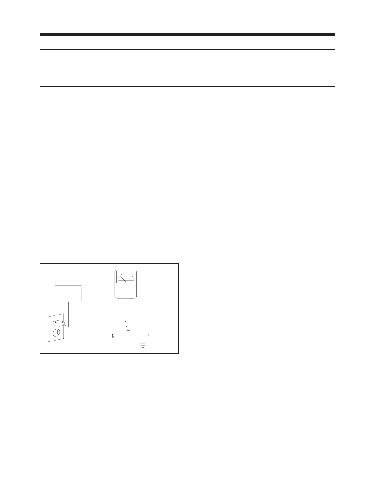
3. Check for Electricity Leakage (Figure 1-1)
Warning: Do not use an insulated transformer for checking the leakage. Use only those current leakage testers
or mirroring systems that comply with ANSIC 101.1 and
the Underwriter Laboratory's specifications (UL1410,
59.7).
Fig. 1-1 AC Leakage Test
4. A high voltage is maintained within the specified limits
using safety parts, calibration and tolerances. When
voltage exceeds the specified limits, check each special
part.
5. Warning for Engineering Changes:
Never make any changes or additions to the circuit
design or the internal part for this product.
Ex: Do not add any audio or video accessory
connectors. This might cause physical damage.
Furthermore, any changes or additions to the original
design/engineering will invalidate the warranty.
6. Warning - Hot Chassis:
Some TV chassis are directly connected to one end of
the AC power cord for electrical reasons.
Without insulated transformers, the product can only be
repaired safely when the chassis is connected to the
earthed end of the AC power source.
To make sure the AC power cord is properly connected,
follow the instructions below. Use the voltmeter to
measure the voltage between the chassis and the
earthed ground. If the measurement is over 1.0V, unplug
the AC power cord and change the polarity before reinserting it. Measure the voltage between the chassis
and the ground again.
7. Some TV chassis are shipped with an additional
secondary grounding system. The secondary system is
adjacent to the AC power line. These two grounding
systems are separated in the circuit using an
unbreakable/unchangeable insulation material.
8. When any parts, material or wiring appear overheated or
damaged, replace them with new regular ones
immediately. When any damage or overheating is
detected, correct this immediately and make a regular
check of possible errors.
9. Check for the original shape of the lead, especially that
of the antenna wiring, any sharp edges, the AC power
and the high voltage power. Carefully check if the wiring
is too tight, incorrectly placed or loose. Never change the
space between the part and the printed circuit board.
Check the AC power cord for possible damages. Keep
the part or the lead away from any heat-emitting
materials.
Precaution
Samsung Electronics 1-1
To avoid possible damages or electric shocks or exposure to radiation, follow the instructions below with regard to safety,
installation, service and ESD.
1. Precaution
1-1 Safety Precautions
(READING SHOULD
DEVICE
UNDER
TEST
EXPOSED METAL
2-WIRE CORD
ALSO TEST WITH
PLUG REVERSED
(USING AC ADAPTER
PLUG AS REQUIRED)
TEST ALL
SURFACES
LEAKAGE
CURRENT
TESTER
NOT BE ABOVE
0.5mA)
EARTH
GROUND
Page 6

10. Safety Indication:
Some electrical circuits or device related materials
require special attention to their safety features, which
cannot be viewed by the naked eye. If an original part is
replaced with another irregular one, the safety or
protective features will be lost even if the new one has a
higher voltage or more watts.
Critical safety parts should be bracketed with ( ).
Use only regular parts for replacements (in particular,
flame resistance and dielectric strength specifications).
Irregular parts or materials may cause electric shock or
fire.
Precaution
1-2 Samsung Electronics
!
Page 7

1. The service instructions are printed on the cabinet, and
should be followed by any service personnel.
2. Make sure to unplug the AC power cord from the power
source before starting any repairs.
(a) Remove or re-install parts or assemblies.
(b) Disconnect the electric plug or connector, if any.
(c) Connect the test part in parallel with the electrolytic
capacitor.
3. Some parts are placed at a higher position than the
printed board. Insulated tubes or tapes are used for this
purpose. The internal wiring is clamped using buckles to
avoid contact with heat emitting parts. These parts are
installed back to their original position.
4. After the repair, make sure to check if the screws, parts
or cables are properly installed. Make sure no damage is
caused to the repaired part and its surroundings.
5. Check for insulation between the blade of the AC plug
and that of any conductive materials (i.e. the metal
panel, input terminal, earphone jack, etc).
6. Insulation Check Process: Unplug the power cord from
the AC source and turn the switch on. Connect the insulating resistance meter (500v) to the AC plug blade.
The insulating resistance between the blade of the AC
plug and that of the conductive material should be more
than 1 ㏁.
7. Any B+ interlock should not be damaged.
If the metal heat sink is not properly installed, no
connection to the AC power should be made.
8. Make sure the grounding lead of the tester is connected
to the chassis ground before connecting to the positive
lead. The ground lead of the tester should be removed
last.
9. Beware of risks of any current leakage coming into
contact with the high-capacity capacitor.
10. The sharp edges of the metal material may cause
physical damage, so ensure wearing protective gloves
during the repair.
11. Due to the nature of plasma display panels, partial afterimages may appear if a still picture is displayed on the
screen for a long period of time.
This is caused by brightness deterioration due to the
storage effect of the panel, and to prevent this from
happening, we recommend that the brightness and contrast are reduced.
(e.g.) Contrast: 25, Brightness: 50
Precaution
Samsung Electronics 1-3
Warning 1: First carefully read the "Safety Instruction" in this service manual.
When there is a conflict between the service and the safety instructions, follow the safety instruction at all times.
Warning 2: Any electrolytic capacitor with the wrong polarity will explode.
1-2 Servicing Precautions
Page 8

1-3 Static Electricity Precautions
1. Some semi-conductive ("solid state") devices are
vulnerable to static electricity. These devices are known
as ESD. ESD includes the integrated circuit and the field
effect transistor. To avoid any materials damage from
electrostatic shock, follow the instructions described
below.
2. Remove any static electricity from your body by
connecting the earth ground before handling any
semi-conductive parts or ass'ys. Alternatively, wear a
dischargeable wrist-belt.
(Make sure to remove any static electricity before
connecting the power source - this is a safety instruction
for avoiding electric shock)
3. Remove the ESD ass'y and place it on a conductive
surface such as aluminum foil to prevent accumulating
static electricity.
4. Do not use any Freon-based chemicals.
Such chemicals will generate static electricity that
causes damage to the ESD.
5. Use only grounded-tip irons for soldering purposes.
6. Use only anti-static solder removal devices.
Most solder removal devices do not support an
anti-static feature. A solder removal device without an
anti-static feature can store enough static electricity to
cause damage to the ESD.
7. Do not remove the ESD from the protective box until the
replacement is ready. Most ESD replacements are
covered with lead, which will cause a short to the entire
unit due to the conductive foam, aluminum foil or other
conductive materials.
8. Remove the protective material from the ESD
replacement lead immediately after connecting it to the
chassis or circuit ass'y.
9. Take extreme caution in handling any uncovered ESD
replacements. Actions such as brushing clothes or lifting
your leg from the carpet floor can generate enough static
electricity to damage the ESD.
Precaution
1-4 Samsung Electronics
CAUTION
These servicing instructions are for use by
qualified service personnel only.
To reduce the risk of electric shock do not
perform any servicing other than that contained in the
operating instructions unless you are qualified to do so.
Page 9

Precaution
Samsung Electronics 1-5
1-4 Installation Precautions
1. For safety reasons, more than two people are required
for carrying the product.
2. Keep the power cord away from any heat emitting
devices, as a melted covering may cause fire or electric
shock.
3. Do not place the product in areas with poor ventilation
such as a bookshelf or closet. The increased internal
temperature may cause fire.
4. Bend the external antenna cable when connecting it to
the product. This is a measure to protect it from being
exposed to moisture. Otherwise, it may cause a fire or
electric shock.
5. Make sure to turn the power off and unplug the power
cord from the outlet before repositioning the product.
Also check the antenna cable or the external connectors
if they are fully unplugged. Damage to the cord may
cause fire or electric shock.
6. Keep the antenna far away from any high-voltage cables
and install it firmly. Contact with the high-voltage cable or
the antenna falling over may cause fire or electric shock.
7. When connecting the RF antenna, check for a DTV
receiving system and install a separate DTV reception
antenna for areas with no DTV signal.
8. When installing the product, leave enough space (4")
between the product and the wall for ventilation
purposes.
A rise in temperature within the product may cause fire.
9. When moving a PDP with attached speakers, detach the
speakers first before moving the main body.
Moving the PDP main body without separating the
speakers may cause the speakers to detach, possibly
causing damage or injury.
Page 10

1-6 Samsung Electronics
MEMO
Page 11
Product Specification
Samsung Electronics 2-1
2. Product Specification
2-1 Product Features
Block Specfication Major IC Remark
RF Digital/Analog (DTV Built In)
VSB NIM Tuner
S5H2010A01 (Eagle+)
PDP Module Samsung SDI V4 Module 42" HD New Module
Power Samsung electro mechanics SMPS 42" HD SMPS New SMPS
Video
NTSC 3.58, ATSC
HDMI
DNIe Lite
Component, PC
STP22 (Scaler)
SDP43 (DNIe Lite)
MST9883 (PC A/D)
SiI9993 (HDMI)
Sound
Speaker : 15W + 15W
SRS TruSurround XT, Dolby Digital
MSP4440K, NSP-6241
TAS5122
Optical, Coaxial
Output
Cabinet P5 Design New Cabinet
■ Chip Description
- DNVS303EH261A Tuner : ATSC/NTSC VSB NIM Tuner
- STP22 : Component, CVBS, Y/C, HDMI, PC input Video signal processor
- SDP43 : The DNIe IC for visual quality improvement. (DNIe Lite)
- Sii9993 : Converts the TMDS signal on the HDMI input into 8 bit digital R, G, B signals.
- MSP4440K : Sound Processing IC
- MST9883 : A/D converts the R, G, B input signal from 15 Pin PC video to 8 bit digital R, G, B signals.
- NSP6241A: Sound PWM IC
- TAS5122 : Sound AMP IC
- S5H2010A01 : MPEG Decoder IC (EAGLE+)
- S3C2800X01 : CPU IC
- 3F8668 : Generates various control signals required for operating the circuit.
The software is downloaded through PC D-SUB Jack. (Sub Micom)
Page 12

Product Specification
2-2 Samsung Electronics
2-2 Key Features
Model HP-R4272C
Dimensions Display
41.7(W) x 29.1(H) x 3.88(D) inches (Without Stand)
41.7(W) x 30.7(H) x 13.4(D) inches (With Stand)
Weight Display
39.8Kg / 87.74 lbs (Without Stand)
44.5Kg / 98.10 lbs (With Stand)
Voltage AC 110 V~, 60 Hz
Power Consumption 380W
Number of Pixels 1024(H) x 768(V)
Screen Size 42 inches
ANTENNA input
ANT 1 - CABLE IN
ANT 2 - AIR IN
※ 75Ω unbalanced
VIDEO input
AV1, AV2
S-VIDEO1, S-VIDEO2
COMPONENT1 - 480i/480p/720p/1080i
COMPONENT2 - 480i/480p/720p/1080i
PC
HDMI (DVI Compatible)
AUDIO input
AV1, AV2
S-VIDEO1, S-VIDEO2
COMPONENT1 - 480i/480p/720p/1080i
COMPONENT2 - 480i/480p/720p/1080i
PC
DVI
AV Output AUDIO (L/R)
Speaker Output
15W + 15W (8Ω )
Audio Output
OPTICAL(DIGITALOUT)
COAXIAL(DIGITALOUT)
ETC
DNIe Lite, Anynet, Color Weakness, My Color Control, SRS TruSurround XT, Dolby Digital,
Built-in Speaker/Stand
New Function Energy Saving, Screen Burn Protection
■ H/W Configuration
- DTV Module : S5H2010A01 (MPEG Decoder IC, Eagle+)
- Video : STP-22, MST9883, SiI9993, DNIe Lite
- Sound : MSP4440K, NSP-6241, TAS5122
- Tuner : UMX-NT-043 (RF-Splitter), DNVS303EH261A (VSB NIM Tuner)
- CPU : S3C2800X01, S3F866B, P_PCFM_012
■ S/W Configuration
- Main Program : TE28F640 (Flash memory)
- Sub-Micom : S3F866B
- DDC : 24C02 x2 (Analog DDC Data, Digital DDC Data)
- EEPROM : 24C256 (White balance data and Factory initial data)
Page 13

Product Specification
Samsung Electronics 2-3
■ Picture
- System : Video → ATSC / NTSC
- Progressive
- Output resolution : 1024 x 768p
- OSD : Smart user Interface Grade 1
- Picture Enhancement : DNIe Lite
- Still picture, Noise reduction
- Comb Filter : 3D comb filter
- PIP : Large, Double 1, Double 2
- Picture Size : 16:9, Panorama, Zoom1, Zoom2, 4:3 (AV, S-Video, Component 480i/480p))
16:9, 4:3 (Component 720p/1080i, PC, HDMI)
■ Sound
- System : Stereo
- Dolby Digital, TruSurround XT
- Output : 15W + 15W
- Speaker : Built-in
- Optical/Coaxial Sound Output : Dolby Digital, PCM (DTV), PCM (HDMI)
■ Feature
- Component Interface(480i/480p/720p/1080i, Y/Pb/Pr)
- Digital Interface : HDMI (480p/720p/1080i)
- Auto Program
- Sleep Timer : 180 Minutes
- Anynet Interface
- My Color Control
- Color Weakness
- Energy Saving
- Screen Burn Protection
■ In/Out Terminals
- 1 Monitor audio Output
- 2 Component Inputs
- 15 Pin PC D-sub Input
- 1 HDMI Input
- 2 SPDIF Output (Optical, Coaxial)
- 2 RF Input : Cable/Air
- 2 AV Inputs
- 2 S-Video Inputs
■ Remocon
- TM76
■ Power Supply
- 110V~, 60Hz
■ Power Comsumption : 380W
■ HDMI input mode : 480p, 720p, 1080i
■ Note
- You can input the DVI signal using the DVI ↔ HDMI conversion cable.
- When connecting HDMI input using the DVI ↔ HDMI conversion cable, connect the sound signal to the DVI Audio IN port
using a separate connection cable.
Page 14

Product Specification
2-4 Samsung Electronics
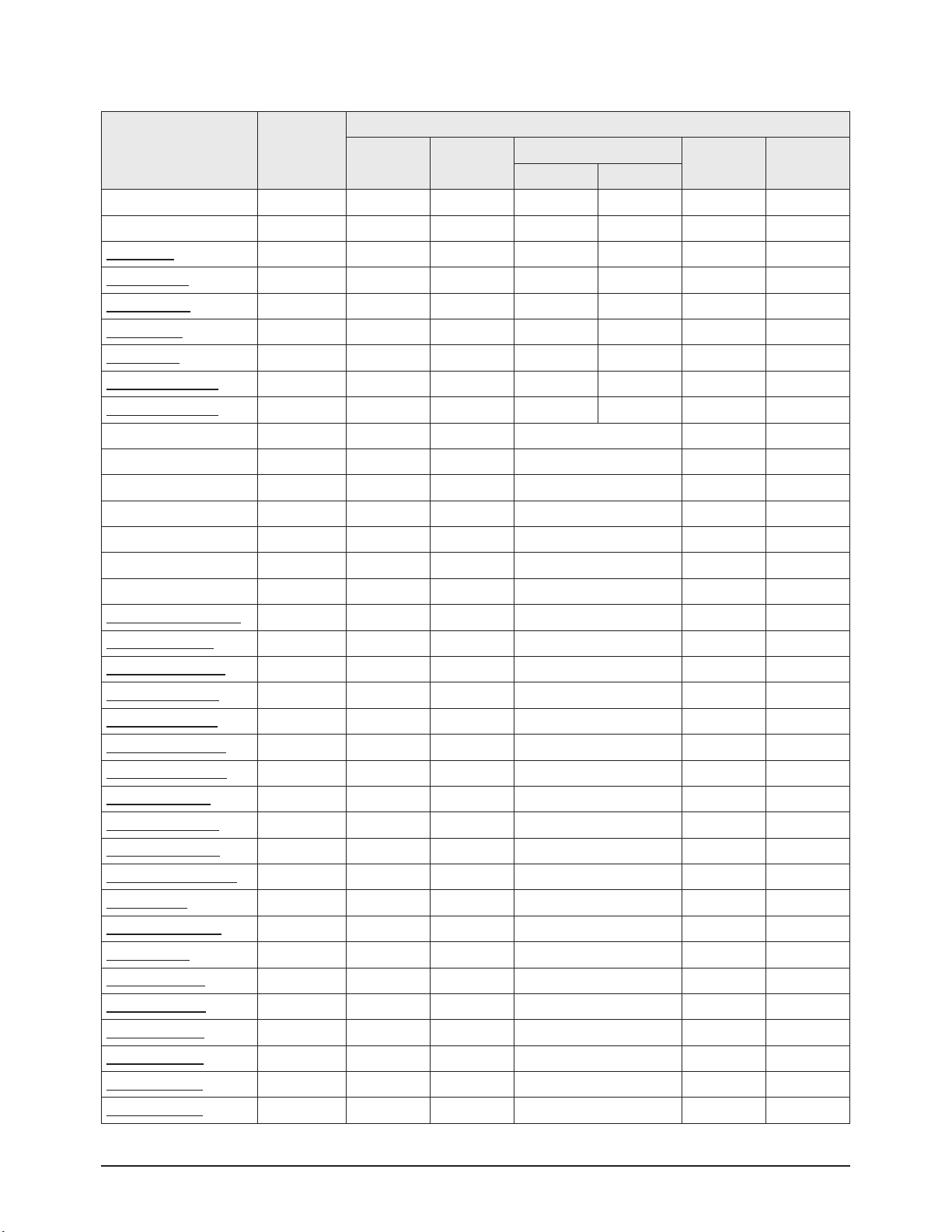
■ PC(D-Sub 15Pin Jack) Input mode
The table below shows all of the display modes that are supported. (N : Negative, P : Positive)
Video Signal
Resolution
(Dot X Line)
Vertical
Frequency (Hz)
Horizontal
Frequency (KHz)
Vertical
Polarity
Horizontal
Polarity
IBM PC / AT
Compatible
640 X 350 70.086 31.469 P N
720 X 400 70.087 31.469 N P
640 X 480
59.940 31.469 N N
70.000 35.000 N/P N/P
72.809 37.861 N N
75.000 37.500 N N
800 X 600
56.250 35.156 N/P N/P
60.317 37.879 P P
70.000 43.75 N/P N/P
72.188 48.077 P P
75.000 46.875 P P
1024 X 768
60.004 48.363 N N
70.069 56.476 N N
72.000 57.672 N/P N/P
75.029 60.023 P P
Page 15

Product Specification
Samsung Electronics 2-5
2-3 Specifications Analysis
Model SP-P4231 HP-P4261 HP-R4272C
Design
Basic
Display Type PDP TV PDP TV PDP TV
Built-In Tuner X X
○
Resolution
852 x 480 1024 x 768 1024 x 768
PDP Module Samsung SDI V3 Samsung SDI V3 Samsung SDI V4
Screen Size 42" 42" 42"
Picture ratio 16 : 9 16 : 9 16 : 9
Power Consumption 330 W 330 W 380 W
Dimensions
40.5"(W) x 24.9"(H) x 3.4"(D)
(Without Stand)
41.4"(W) x 29.7"(H) x 3.4"(D)
(Without Stand)
41.7"(W) x 29.1"(H) x 3.88"(D)
(Without Stand)
Weight 66.1 Lbs (Without Stand) 79 Lbs (Without Stand) 87.7 Lbs (Without Stand)
Picture
Brightness 1,000 Cd/m2 1,000 Cd/m2 1,500 Cd/m2
Contrast Ratio 3,000 : 1 3,000 : 1 10,000 : 1
Picture Enhacer DNIe 2 DNIe 3 DNIe Lite
Comb Filter
○ ○ ○
Audio
Equalizer 5 Band 5 Band 5 Band
Auto Volume Control
○ ○ ○
Surround Sound SRS TruSurround XT SRS TruSurround XT SRS TruSurround XT Dolby Digital
Speaker Output 15W + 15W 15W + 15W 15W + 15W
Features
PIP
○ ○ ○
Double Window
○ ○ ○
Caption
○ ○ ○
Still Image
○ ○ ○
EPG X X
○
My Color Control X
○ ○
Color Weakness X
○ ○
Energy Saving X X
○
Anynet X X
○
Connections
Antenna 1 1 2 (Cable/Air)
AV Input 1 3 2
S-Video 1 2 2
Component 1 2 2
PC(D-SUB) 1 1 1
DVI 1 1 X
HDMI X X 1
Sub Woofer X
1
X
Optical X X 1
Coaxial X X 1
ETC
Speaker/Stand Built-in Stand Built-in Speaker/Stand Built-in Speaker/Stand
FCC Class Class B Class B Class B
Page 16

Product Specification
2-6 Samsung Electronics
2-4 Accessories
Accessories Item Item code Remark
Supplied Accessories
Owner's Instructions BN68-00825J
Samsung Service center
Remote Control
AAA Batteries
BN59-00462A
4301-000103
Power Cord 3903-000144
Anynet Cable BN39-00518A
Accessories that can be purchased
additionally
S-VIDEO Cable -
Internal shopping mall
HDMI Cable -
HDMI/DVI cable -
Component Cables (RCA) -
PC Cable -
PC Audio Cable -
Optical Cable -
Coaxial Cable -
Antenna Cable -
Page 17
Alignment & Adjustment
Samsung Electronics 3-1
3. Alignment & Adjustment
3-1 Service Instruction
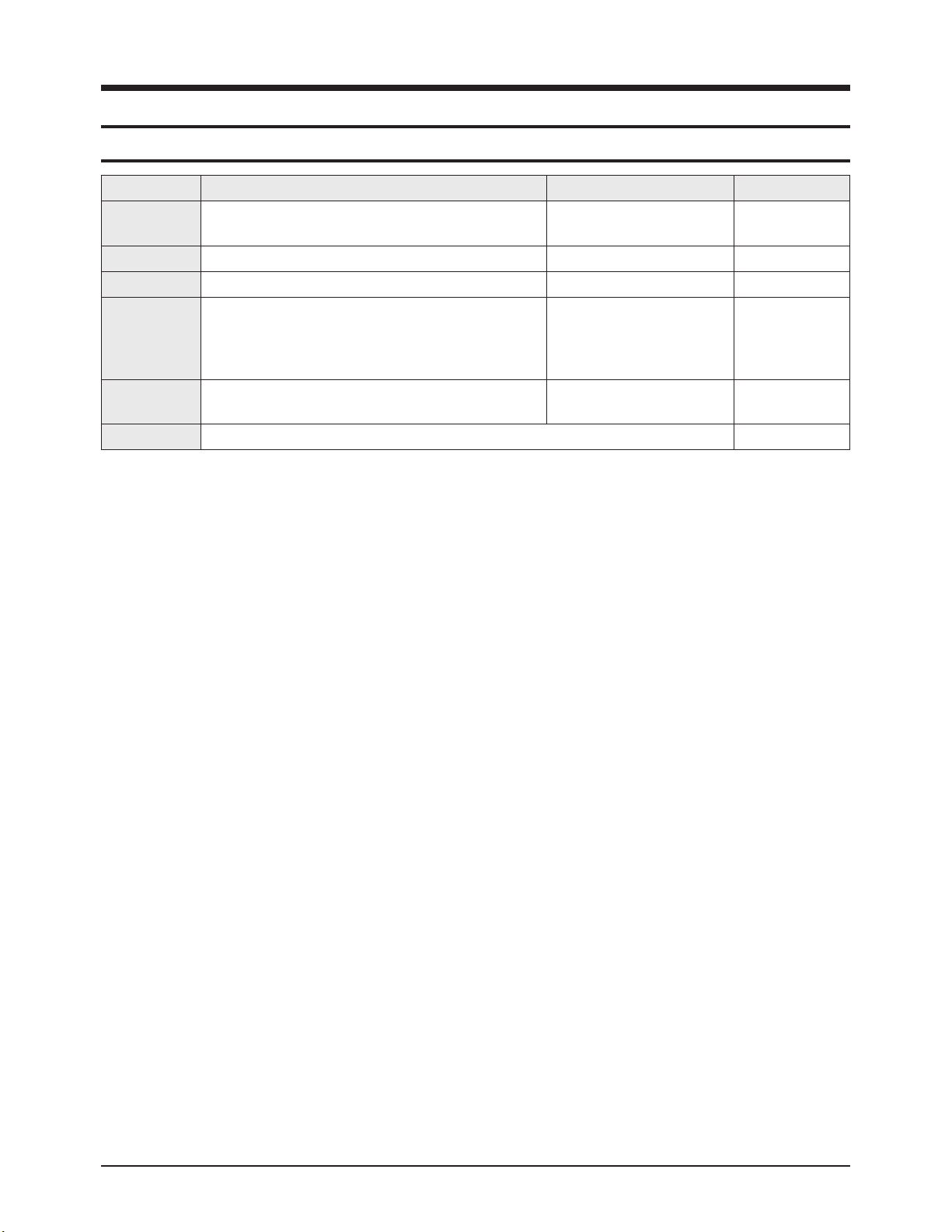
* Check items listed after changing each
Replaced Items Item Code Check Items
ASSY PCB MISC-MAIN BN94-00733A
1) Auto Program
2) Let the user go through subscription process after contacting
user's cable service provider.
ASSY PCB P-SMPS(MAIN) BN96-02213A Voltage Adjustment
ASSY PCB P-SMPS(DC DC) BN96-01856A Voltage Adjustment
ASSY PDP P-LOGIC BOARD BN96-02035A -
ASSY PDP P-X MAIN BOARD BN96-02032A -
ASSY PDP P-Y MAIN BOARD BN96-02033A -
ASSY PDP P-Y UPPER BUFFER BOARD BN96-02034A -
ASSY PDP P-Y LOWER BUFFER BOARD BN96-02216A -
ASSY PDP P-ADDRESS E BUFF BOARD BN96-02036A -
ASSY PDP P-ADDRESS F BUFF BOARD BN96-02037A -
※ When replacing the SMPS or PDP panel, you have to check the voltage printed on the panel sticker and adjust it.
Page 18

Alignment & Adjustment
3-2 Samsung Electronics
3-2 How to Access Service Mode
■ Using the Customer Remote
1. Turn the power off and set to stand-by mode.
2. Press the remote buttons in this order; MUTE-1-8-2- POWER ON to turn the set on.
3. The set turns on and enters service mode.
4. Press the Power button to exit and store data in memory.
※ If you fail to enter service mode, repeat steps 1 and 2 above.
5. Initial SERVICE MODE DISPLAY State
※ "T-STRANUS0S-0036" and "T-STRANUS5-0117" are firmware version.
The firmware version is subject to change without notice.
6. Buttons operations within Service Mode
MENU Full Menu Display / Move to Parent Menu
Direction keys ▲ / ▼
Item Selection by Moving the Cursor
Direction keys ◀ / ▶
Data Increase/Decrease for the Selected Item
Source Cycles through the active input source that are connected to the unit
HDMI/DTV HD
Calibration Adjust
Option Byte Test Pattern
White Balance Chip Debugger
SVP-EX Checksum
MST9883 Option PDP
MSP34XX RESET
YC Delay
DNIe Lite
T-STRANUS0S-0036 Jan 12 2005
T-STRANUS5-0117 [Sec : 29]
Page 19
Alignment & Adjustment
Samsung Electronics 3-3
3-3 Factory Data
★ The underlined are items applied during the service adjustment. None of the others should be adjusted.
1. Calibration
3. White Balance
ITEM
AV Calibration Off
Comp Calibration Off
PC Calibration Off
2. Option Byte
ITEM
Caption Level 16
MGT-VCT Ver. Check 0
V-Chip Enable 1
Watchdog Enable 1
Spread Enable PC 1
Clock Adjust 4
Nim Version T310
MSP Version G
New_WB_CbCr 1
ITEM Range
Initial Values of Input Modes
TV/AV/S-video Component PC HDMI
Sub Bright(SVP) 0~1204 447 457 480 450
R-Offset 0~1204 511 516 512 512
G-Offset 0~1204 512 512 512 512
B-offset 0~1204 513 513 512 508
Sub Contrast(DNIe) 0~255 128 128 128 128
R-Gain 0~255 120 120 128 120
G-Gain 0~255 120 120 128 120
B-Gain 0~255 120 140 128 140
Sub Contrast(SVP) 256 256 256 256
Page 20
Alignment & Adjustment
3-4 Samsung Electronics
4. SVP-EX
ITEM Range
Initial Values of Input Modes
TV AV/S-Video
Component
PC HDMI
480i/P 720/1080
00.Comb Filter
01.Y-Filter
01.Peaking
01.V-PosGain 0~15 4 4 1 2 0 1
02.V
-NegGain
0~15 4 4 4 5 0 4
03.V
-BpGain
0~32 16 16 16 16 16 16
04.V-HfGain 0~32 20 20 20 20 20 20
05.V-Peaking-TH 1 0~256 16 16 16 16 16 16
06.V-Peaking-TH 3 0~256 128 128 128 128 128 128
02.NR
01.Y-NR-Off
02.C-NR-Off
03.Y-NR-On
04.C-NR-On
03.Deinterlace
01.Motion
04.Picture Gain Adjust
01.TCD3 Contrast 0~255 120 120 120 - 120
02.TCD3 Brightness 0~255 49 49 49 - 49
03.TCD3 YC Delay 0~15 1 0 1 - 1
04.Analog Y Offset 0~1023 61 61 61 - 61
05.Analog PB Offset 0~1023 512 512 512 - 512
06.Analog PR Offset 0~1023 512 512 512 - 512
07.Analog Y Gain 0~255 217 217 217 - 217
08.Analog PB Gain 0~255 225 225 225 - 225
09.Analog PR Gain 0~255 225 225 225 - 225
10.Black Level Setting 0~255 0 0 0 - 0
11.Brightness 0~255 125 125 125 - 125
12.UserColor(MAX) 0~127 127 127 120 - 127
06.WB Control
01.MP R-Offset2 0~1023 512 512 512 512 512
02.MP
G-Of
fset2
0~1023 512 512 512 512 512
03.MP B-Offset2 0~1023 512 512 512 512 512
04.PP R-Offset2 0~1023 512 512 512 512 512
05.PP
B-Offset2
0~1023 512 512 512 512 512
06.PP B-Offset2 0~1023 512 512 512 512 512
Page 21

Alignment & Adjustment
Samsung Electronics 3-5
ITEM
Sub
Address 'h
Range
Initial Values of Input Modes
TV
AV/
S-Video
Component HDMI
PC
480i 480p 720p 1080i 480P 720P 1080i
07. Chroma
01.LtiPeakGain P1 Luma/Croma 0x0F [4:0] 0~31 31 31 31 31 31 31 31 31 31
02.LtiStep P1 Luma/Croma 0x0F [6:5] 0~3 2 2 2 2 2 2 2 2 2
03.LtiTh P1 Luma/Croma 0x10 [7:0] 0~255 16 16 16 16 16 16 16 16 16
04.LtiGain P1 Luma/Croma 0x11 [4:0] 0~31 8 10 10 10 10 10 10 10 10
05.LowPassGain P1 Luma/Croma 0x12 [4:0] 0~31 8 17 17 7 10 10 17 12 5
06.BandPassGain P1 Luma/Croma 0x13 [4:0] 0~31 13 24 24 10 13 13 8 2 2
07.HighPassGain P1 Luma/Croma 0x14 [4:0] 0~31 10 18 18 2 10 10 2 26 10
08.PeakStep P1 Luma/Croma 0x12 [6:5] 0~3 1 1 1 1 1 1 1 0 0
09.PeakTh1 P1 Luma/Croma 0x15 [7:0] 0~255 7 7 7 7 7 7 7 7 7
10.PeakTh2 P1 Luma/Croma 0x16 [7:0] 0~255 2 2 2 2 0 0 2 2 2
1
1.PeakTh3
P1 Luma/Croma 0x19 [7:0] 0~255 32 32 32 32 32 32 32 32 32
12.PeakN1Factor2
P1 Luma/Croma 0x14 [7:5]
P1 Luma/Croma 0x13 [7:5]
0~63 56 8 8 8 0 0 0 0 0
13.PeakN1Factor1 P1 Luma/Croma 0x1A [5:0] 0~63 40 48 48 40 48 48 40 40 40
14.CoringTh P1 Luma/Croma 0x17 [7:0] 0~255 2 2 2 2 2 2 2 2 2
15.CoringGain P1 Luma/Croma 0x18 [4:0] 0~31 8 0 8 8 8 8 8 8 8
16.PeakPosGain P1 Luma/Croma 0x49 [7:4] 0~15 1 1 1 3 1 1 1 1 1
17.PeakNegGain P1 Luma/Croma 0x49 [3:0] 0~15 1 1 1 3 1 1 1 1 1
18.BypassHsharp P1 Luma/Croma 0x1A [6] 0~1 0 0 0 0 0 0 0 0 0
19.DctiGain P1 Luma/Croma 0x28 [3:0] 0~15 4 4 10 10 10 10 4 4 4
20.DctiStep P1 Luma/Croma 0x29 [6:4] 0~7 1 1 7 1 1 1 1 1 1
21.DctiEnable P1 Luma/Croma 0x29 [7] 0~1 1 1 1 1 1 1 1 1 1
22.DctiThres P1 Luma/Croma 0x2A [7:0] 0~255 12 12 12 12 12 12 12 12 12
08.CLK_A P5. DSS 0x0A[15:0] 16~17 16 16 16 17
09.CLK_B P5. DSS 0x0B[15:0] 0~255 96 96 96 0
10.GAMMA 0 0 0 0
Page 22

Alignment & Adjustment
3-6 Samsung Electronics
6. MSP34XX
7. YC Delay
5. MST9883
ITEM Range
Initial Values of Input Modes
TV/AV/SVHS Component PC HDMI
R_Gain 0~255 11 2 11 2 112 11 2
G_Gain 0~255 112 112 11 2 112
B_Gain 0~255 113 11 3 113 11 3
R_Offset 0~255 122 122 122 122
G_Offset 0~255 121 121 121 121
B_Of
fset
0~255 122 122 122 122
ITEM Range Initial
FM-Prescale 0~255 0x20
NICAM-Prescale 0~255 0x20
A
V-Prescale
0~255 0x1C
I2S_1 Prescale 0~255 0x10
I2S_3 Prescale 0~255 0x11
Carrier Mute 0~255 On
Pilot High 0~255 0x0D
Pilot Low 0~255 0x07
Scart1 Out Volume 0~255 0x6D
Scart2 Out V
olume
0~255 0x73
ITEM Range
Initial Values of Input Modes
TV/AV/SVHS Component PC HDMI
RF PAL-B/G 0~255 0
- - -
RF PAL-D/K 0~255 0
RF PAL- I 0~255 0
RF SECAM-B/G 0~255 0
RF SECAM-D/K 0~255 0
RF SECAM-L/L' 0~255 0
RF NTSC3.58 0~255 0
RF NTSC4.43 0~255 0
AV PA L 0~255 0
AV SECAM 0~255 0
AV NTSC 3.58 0~255 0
AV NTSC4.43 0~255 0
AV PAL60 0~255 0
Page 23

Alignment & Adjustment
Samsung Electronics 3-7
8. DNIe Lite
ITEM Range
Initial Values of Input Modes
TV/AV/SVHS Component PC HDMI
01.PATT_SEL 0~63 0 0 0 0
02.BLACK_TILT 0~255 125 125 80 120
03.BLACK_GAINMAX 0~1023 380 390 370 380
04.TEST_MCC 0~255 0 0 0 0
05.OVERLAP_MCM 0~255 0 0 0 0
06.AREA_EN_MCC 0~255 31 31 31 31
07.I2C Offset Mean 0~63 16 10 10 10
08.I2C Ana Check 0 0 0 0
09.White Balance(Post)
1.R-Offset(Post) -512~511 0 0 0 0
2.G-Offset(Post) -512~511 0 0 0 0
3.B-Offset(Post) -512~511 0 0 0 0
4.R-Gain(Post) 0~255 0 128 128 128
5.G-Gain(Post) 0~255 0 128 128 128
6.B-Gain(Post) 0~255 0 128 128 128
7.Com_Of
fset_Sel
0,1 1 0 0 0
8.Com_Gain_Sel 0,1 1 0 0 0
10.ColorT
one Cool2
Refer to Table 3
11.ColorTone Cool1
12.ColorTone Normal
13.ColorTone Warm1
14.ColorTone Warm2
15. MCM_EN 0,1 1 1 1 1
16. TEMP_DEST 0~255 150 150 150 150
17. CB5_HIGH 0~255 142 143 156 141
18. CR5_HIGH 0~255 125 123 126 124
19. CB5_LOW 0~255 126 126 126 127
20. CR5_LOW 0~255 129 129 129 128
Page 24

Alignment & Adjustment
3-8 Samsung Electronics
9. Adjust
ITEM Range
Initial Values of Input Modes
TV/AV/SVHS Component PC HDMI
01.V
ideo Mute Time
0~63 5 - - 5
02.Melody Volume 0~63 10 - - 20
03.Dynamic Contrast 0 0 0 0
04.Dynamic Bright 0 0 0 0
05.Dynamic Color 0 0 0 0
06.Dynamic Sharpness 0 0 0 0
07.Standard Contrast 0 0 0 0
08.Standard Bright 0 0 0 0
09.Standard Color 0 0 0 0
10.Standard Sharpness 0 0 0 0
11.Movie Contrast
12.Movie Bright
13.Movie Color
14.Movie Sharpness
15.RF_dB_1 Rf AV
-.Noise
Thres1
0~255 20 20
-.LowPassGain1 0~31 7 14
-.BandPassGain1 0~31 12 19
-.HighPassGain1 0~31 6 16
-.PeakStep1 1 1
-.CoringTh1 2 2
-.CoringGain1 8 2
-.PosGain1 1 1
-.NegGain1 1 1
-.V-PosGain1 2 2
-.V-NegGain1 2 2
16.RF_dB_2
-.Noise Thres2 30 40
-.LowPassGain2 5 10
-.BandPassGain2 8 15
-.HighPassGain2 0 8
-.PeakStep2 0 0
-.CoringTh2 12 8
-.CoringGain2 8 10
-.PosGain2 1 1
-.NegGain2 1 1
-.V-PosGain2 1 1
-.V-NegGain2 1 1
Page 25

Alignment & Adjustment
Samsung Electronics 3-9
ITEM Range
Initial Values of Input Modes
TV/AV/SVHS Component PC HDMI
17.RF_dB_3
-.Noise Thres3 40 60
-.LowPassGain3 0 5
-.BandPassGain3 0 12
-.HighPassGain3 0 4
-.PeakStep3 0 0
-.CoringTh3 26 14
-.CoringGain3 15 16
-.PosGain3 0 0
-.NegGain3 0 0
-.V-PosGain3 0 0
-.V-NegGain3 0 0
10. Test Pattern
01. OSD Pattern
01. Luma Ramp(32 Step)
02. Luma Ramp(128 Step)
03. White 16
04. White 240
05. Color Bar
06. RGB Ramp(32 Step)
07. Cross Hatch(20X20)
02. 1 Channel Pattern
01. Y-Filter
02. V-PosGain
03. V-NegGain
04. V-BpGain
05. V-HfGain
06. V-Peaking-Th1
07. V-Peaking-Th3
03. 2 Channel Pattern
01. Luma Ramp(32 Step)
02. Luma Ramp(128 Step)
03. White 16
04. White 240
05. Color Bar
06. RGB Ramp(32 Step)
07. Cross Hatch(20X20)
11. Chip Debugger : ON/OFF (Select this menu before downloading sub-micom image)
12. Checksum [XXXX]
Page 26

Alignment & Adjustment
3-10 Samsung Electronics
ITEM Range Initial
01.Pixel Shift 0
-.Pixel Shift T
est
0~1 0
-.Number Range 0~1 1
-.Line Range 0~1 1
02.Sound SD delay 0~2 1
03.Sound HD delay 0~2 1
04.Sound DTV delay 0~1 0
05.DDC Write 0~1 0
06.Auto Voltage Adj 5
07.Image Sticking 0
08.Error Mode Check 1
09.Error Code Table 4
10.Patt Sel 0
11.Control Key Lock 0
12.FCRL
Con
1
13. Option PDP : ON/OFF
14. Reset : Factory reset (User settings in OSD is initialized.)
Page 27

Alignment & Adjustment
Samsung Electronics 3-11
3-4 Service Adjustment
3-4-1 White Balance Adjustment
1. W/B Adjustment is required for the following sequence.
Color Calibration (CVBS,Component,PC) → W/B Adjustment (HDMI,Component,CVBS)
2. Adjustment Method (Signal equipment : MSPG-925LTH, Measurement equipment : CA210)
3. You can adjust the white ratio in factory mode (Calibration, White Balance menu).
4. Since the adjustment value and the data value vary depending on the input source, you have to adjust these in HDMI,
Component and AV modes.
5. The optimal values for each mode are configured by default. (Refer to Table 2 and 3)
Equipment: CA-210 & Master MSPG925 Generator
Calibration Pattern: Master MSPG925 #24 "Lattice pattern"
W/B adjustment Pattern: Master MSPG925 #16 "ABL pattern"
Use other equipment only after comparing the result with that of the Master equipment.
Set Aging Time: Longer than 30 min.
Pattern Resolution: Given below.
Calibration Available/None and Pattern used for Calibration.
White Balance coordinates configuration result. (On the basis of the ABL pattern. The resolutions are given below)
For PC Mode, perform only calibration and do not perform additional W/B adjustments.
Input mode Calibration Pattern
CVBS IN (Model_#1) Perform in NTSC B&W Pattern #24 Lattice
Component IN (Model_#6) Perform in 720p B&W Pattern #24 Lattice
PC Analog IN (Model_#21)
Perform in VESA XGA (1024x768)
B&W Pattern #24
Lattice
HDMI IN None -
<Table 1>
<Table 2>
Input mode x y Y(fL) T(K)/MPCD
CVBS IN
(NTSC)
H/L 265 265 Do not adjust 15000K/-5
L/L 280 285 1.2 10000K/-5
Component IN
(720p, 60Hz)
H/L 265 265 Do not adjust 15000K/-5
L/L 280 285 1.2 10000K/-5
PC Analog IN None
HDMI IN
(720p, 60Hz)
H/L 265 265 Do not adjust 15000K/-5
L/L 280 285 1.2 10000K/-5
Page 28

Alignment & Adjustment
3-12 Samsung Electronics
Item Warm 2 Warm 1 Normal Cool1 Cool2
AV
Component
HDMI
R Cutoff 128 128 128 128 128
G Cutoff 128 128 128 128 128
B Cutoff 128 128 128 128 128
R Gain 128 128 128 128 128
G Gain 128 128 128 128 128
B gain 128 128 128 128 128
R Cutoff 128 128 128 128 128
G Cutoff 128 128 128 128 128
B Cutoff 128 128 128 128 128
PC
R Gain 128 128 128 128 128
G Gain 128 128 128 128 128
B gain 128 128 128 128 128
R Cutoff 128 128 128 128 128
G Cutoff 128 128 128 128 128
B Cutoff 128 128 128 128 128
R Gain 128 128 128 128 128
G Gain 128 128 128 128 128
B gain 128 128 128 128 128
<Table 3>
Page 29

Alignment & Adjustment
Samsung Electronics 3-13
3-4-2 Conditions for Measurement
1. On the basis of toshiba ABL pattern : High Light level (57 IRE)
■ INPUT SIGNAL GENERATOR : MSPG-925LTH
* Mode NO 1 : 744X484@60 Hz
NO 6 : 1280X720@60 Hz
NO 21 : 1024X768@60 Hz
* Pattern NO 24 : B&W Lattice Pattern
NO 16 : Toshiba ABL Pattern
2. Optical measuring device : CA210 (FL)
Please use the MSPG-925 LTH generator for model HP-R4272C
3-4-3 Method of Adjustment
1. Adjust the basic level of Component,PC and CVBS input signals.
a) Enter factory Calibration, confirm the ADC data (Component, PC, AV Modes).
* ADC default value : Table 1
* You must perform Calibration in the Lattice pattern before adjusting the White Balance.
* If you perform Calibration in a pattern other than the Lattice pattern, it causes a malfunction and the operation will not finish.
In this case, press the "EXIT" button on the remote control to terminate the operation.
1) Enter Service mode.
2) Apply the NTSC Lattice (No 1) pattern signal to the VIDEO IN port.
3) Press the Source key to switch to "AV/S-VIDEO" mode.
4) After confirming that the Lattice pattern appears, select the "Calibration" menu.
5) Select the "AV Calibration" menu.
6) In "AV Calibration Off" status, press the "▶" key to perform Calibration.
7) When Calibration is complete, it returns to the high-level menu.
8) Apply the 720p Lattice (No 6) pattern signal to the COMPONENT IN (Y/Pb/Pr) port.
9) Press the Source key to switch to "COMPONENT" mode.
10) After confirming that the Lattice pattern appears, select the "Calibration" menu.
11) Select the "COMP Calibration" menu.
12) In "COMP Calibration Off" status, press the "▶" key to perform Calibration.
13) When Calibration is complete, it returns to the high-level menu.
14) Apply the 1024x768 Lattice (No 21) pattern signal to the PC IN port.
15) Press the Source key to switch to "PC" mode.
16) After confirming that the Lattice pattern appears, select the "Calibration" menu.
17) Select the "PC Calibration" menu.
18) In "PC Calibration Off" status, press the "▶" key to perform Calibration.
19) When Calibration is complete, it returns to the high-level menu.
20) All Calibration operations are complete.
Picture 2-1 B&W Lattice Pattern
Page 30

Alignment & Adjustment
3-14 Samsung Electronics
2. Adjust the white balance of HDMI,Component and AV Modes.
a) Set the input to the mode in which the adjustment will be made (HDMI, Component, AV adjustment. Do not adjust in PC
Mode.)
* Input signal - AV Mode : Model #1 (744*484 Mode), Pattern #16
- Component/HDMI Mode : Model #6 (1280*720 Mode), Pattern #16
b) Enter the White Balance menu of service mode and confirm the data.
c) Adjust the low light. (Refer to Picture 2-3 for measurement point.)
- Adjust Sub-Bright(SVP) to set the 'Y' value.
- Adjust red offset ('x') and blue offset ('y') to the color coordinates.
* Do not adjust green offset data.
d) Adjust the high light. (Refer to Picture 2-4 for measurement point.)
- Adjust Sub-Contrast(DNIe) to set the 'Y' value.
- Adjust red gain ('x') and blue gain ('y') to the color coordinates.
* Do not adjust the green gain and sub-contrast (Y) data.
Low light
Measurement point
Picture 2-3 Toshiba ABL Pattern
Picture 2-2 Toshiba ABL Pattern
High light
Measurement point
Picture 2-4 Toshiba ABL Pattern
Page 31

Alignment & Adjustment
Samsung Electronics 3-15
3-4-4 How to adjust White Balance with 10 steps gray pattern
1. If you don't have Toshiba ABL pattern, you can adjust white balance with 10 steps gray scale pattern of Picture 2-5.
2. When you measure Low Light, use 20 IRE portions.
And When you measure High Light, use 70 IRE portion. But if color noise is less in 60 IRE than in 70 IRE, 60 IRE is allowed as
a measure point.
3. Perform adjustments 2-b through 2-d from previous page using the 10 step gray scale pattern.
Picture 2-5
Page 32

Alignment & Adjustment
3-16 Samsung Electronics
3-5 Software Upgrade
3-5-1 Source Program Download & Generals
1. Downloading boot code
(1) Turn off PDP-TV.
(2) Connect the RS-232 serial cable to the service jack of PDP-TV.
(3) Enter the DOS Mode and move to the directory including "bootdn.bat" and Excute the file.
(4) Turn on PDP-TV.
2. Downloading application code
(1) Turn off PDP-TV.
(2) Connect the RS-232 serial cable to the service jack of PDP-TV.
(3) Enter the DOS Mode and move to the directory including "appdn.bat" and Excute the file.
(4) Power on PDP-TV.
■ Changing RS-232 serial port and downloaded file
If you want to change serial port, you must edit "bootdn.bat" and "appdn.bat".
"bootdn.bat" → sdn 1 0xdeadbbbb rom
execution file file to be downloaded
port number downloading type : boot image
"appdn.bat" → sdn 1 0xdeadaaaa ram.z
execution file file to be downloaded
port number downloading type : application image
1. Don' t turn off during downloading.
2. sdn.exe, download file and Batch file should be in the same directory.
3. During Downloading, Hyper Terminal should be turned off.
(2) Enter a new name.
(3) Select a modem port.(com 1 and direct connection.)
(4) Set the bit/second to 115200.
(5) Set the data bit to 8
(6) No parity bit.
(7) Set stop bit to 1.
(8) No flow control.
(9) Save in memory.
(10) At this point, the new hyper terminal is ready.
Page 33

Alignment & Adjustment
Samsung Electronics 3-17
3-5-2 How to Check the Version of the Program
1. Procedures for checking in the User Menu
- Select the "Setup" menu in the Menu screen
- Place the cursor over the "On" of "Function Help", and press the "Info" key on the remote control
- The version of the program is displayed at the bottom of the Menu screen
2. Procedures for checking in the Factory Menu
When entering Factory Mode, the version of the software is displayed at the bottom of the menu as described on page 3-2.
Main Program Version
Boot-code Version
Page 34

Alignment & Adjustment
3-18 Samsung Electronics
3-6 Replacements & Calibration
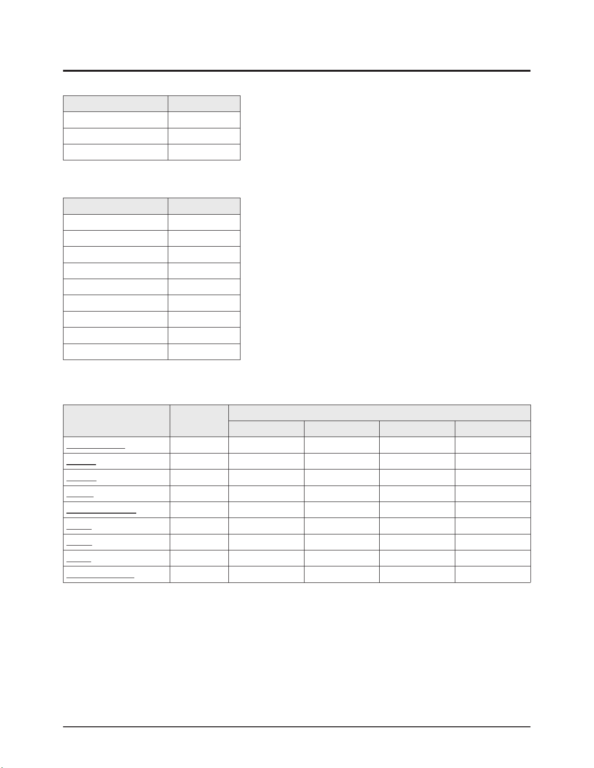
3-6-1 Voltage Adjustment
1. SMPS Panel voltages must be adjusted after changing SMPS-PCB or PDP module.
Range Board Adjustment
Vs 195~215V
SMPS-MAIN
Va 50~70V
Vset 180~210V
SMPS-DC/DCVe 70~110V
Vscan -180~220V
2. A point of adjusting SMPS-MAIN voltage.
SMPS-MAIN SMPS-DC/DC
Voltage
Label
SMPS GND TP
TP : Vs (TOP)
Va (BOT)
Page 35

Alignment & Adjustment
Samsung Electronics 3-19
3. A point of adjusting SMPS-DC/DC.
* Use base chassis of PDP panel as GND point.
Page 36

3-20 Samsung Electronics
MEMO
Page 37

4. Exploded View & Part List
Exploded View & Part List
Samsung Electronics 4-1
Yon can search for the updated part code through ITSELF web site.
URL:http://itself.sec.samsung.co.kr
4-1 HPR4272CX/XAC
Loc.No. Code No. Description Specification Q'ty SA/SNA Remark
CIS7 AA61-60003B SPRING ETC-CS -,SUS304,-,-,OD11.2,N7,OD1 1 S.N.A
M0006 BN63-01633A COVER-REAR SPD-42P5HD,SECC,T0.5 1 S.N.A
M0006 BN63-01634B COVER-REAR SUB SP-R4232,SECC,T1.0 1 S.N.A
M0013 BN96-01789D ASSY STAND P-BASE 42P5,XAC,HIPS HB,BK07, 1 S.A
M0013 BN96-01786A ASSY COVER P-REAR SPD-42P5HD 1 S.A
M0 111 BN63-01813R COVER-STAND 42P5H,XAC,HIPS,T3.5,HB,BK07, 1 S.N.A
M0112 BN63-01631F COVER-FRONT 42P5,HIPS,V0,XAA,BKN1134 1 S.N.A
M0145 BN96-02550A ASSY BOARD P-FUNCTION SCHUBERT,CT5000-36 1 S.A
M0146 BN96-02050B ASSY BOARD P-POWER & IR SCHUBERT,CT5000- 1 S.A
T0003 BN96-02693F ASSY COVER P-FRONT 42P5,XAA,HIPS V0,BKN1 1 S.N.A
T0023 BN64-00336A KNOB POWER 42P5,PC,VIOLET 1 S.N.A
T0044 BN96-01886A ASSY PDP MODULE P M1,SPD-42P5HD,D71A,V4, 1 S.A
T0073 AA63-01078A GASKET-EMI 42P5,T1.5,7,1006 2 S.N.A
T0073 AA63-01079A GASKET-EMI 42P5,T1.5,W7,L614.5 2 S.N.A
T0074 BN59-00462A REMOCON STRAUSS,TM76A,200*54*30,ZILOG,54 1 S.A
T0079 BN94-00733A ASSY PCB MISC-MAIN HPR4272CX/XAC,D71C,SC 1 S.A
T0091 BN94-00732A ASSY PCB MISC-SIDE A/V HPR4272X,D71A,SCH 1 S.N.A
T0152 BN96-01774A ASSY BRACKET P-WALL RIGHT SPD-42P5HD,SEC 1 S.N.A
T0175 BN96-01737A ASSY SPEAKER P 8ohm,P5,42,15W 1 S.A
T0268 3903-000144 CBF-POWER CORD DT,US,BP3/Y,U(IEC C13-RA) 1 S.A
T0275 BN96-02369A ASSY MISC P-INLET HP-R4252,STRAUSS,DOCUM 1 S.A
T0448 BN96-01775A ASSY BRACKET P-WALL LEFT SPD-42P5HD,SECC 1 S.N.A
T0456 BN67-00154A GLASS-FILTER EMI 42 P5,Mesh,44%,1053*639 1 S.N.A
T0555 BN96-01392K ASSY MISC P-BRKT TERMINAL 42D5SD,XEU,SEC 1 S.A
T0603 BN64-00338A WINDOW-RMC 42P5,ACRYL,5% 1 S.N.A
T0074
T0268
T0044
M0112
T0152
T0448
M0013
M0006
T0275
M0006
T0079
M0013
T0555
T0456
T0073
T0003
T0073
M0145
T0175
T0603
CIS7
T0023
T0091
M0 111
M0146
Page 38

Electrical Part List
5. Electrical Part List
5-1 HPR4272CX/XAC Service Item
Yon can search for the updated part code through ITSELF web site.
URL:http://itself.sec.samsung.co.kr
Loc.No. Code No. Description Specification Q'ty SA/SNA Remark
M0013 BN96-01786A ASSY COVER P-REAR SPD-42P5HD 1 S.A
M0013 BN96-01789D ASSY STAND P-BASE 42P5,XAC,HIPS HB,BK07, 1 S.A
M0013 BN96-02666A ASSY STAND P-BAR 42(S5,P5),50 2 S.A
M0018 BN97-00557A ASSY MICOM ,D71C,S3F866B,T-STRANUS5-0117 1 S.A
M0146 BN96-02050B ASSY BOARD P-POWER & IR SCHUBERT,CT5000- 1 S.A
T0003 BN96-02693F ASSY COVER P-FRONT 42P5,XAA,HIPS V0,BKN1 1 S.N.A
T0044 BN96-01886A ASSY PDP MODULE P M1,SPD-42P5HD,D71A,V4, 1 S.A
T0073 BN96-02032A ASSY PDP P-X MAIN BOARD M1,SPD-42P5HD,D7 1 S.A
T0074 BN59-00462A REMOCON STRAUSS,TM76A,200*54*30,ZILOG,54 1 S.A
T0079 BN94-00733A ASSY PCB MISC-MAIN HPR4272CX/XAC,D71C,SC 1 S.A
T0092 BN96-02216A ASSY PDP P-Y BUFFER LOWER BOAR M1,SPD-42 1 S.A
T0096 BN96-02033A ASSY PDP P-Y MAIN BOARD M1,SPD-42P5HD,D7 1 S.A
T0124 BN96-02034A ASSY PDP P-Y UPPER BUFFER BOAR M1,SPD-42 1 S.A
T0128 BN39-00518A CBF SIGNAL-STEREO NA32KO,1P,UL2464#26,20 1 S.A
T0142 BN96-02035A ASSY PDP P-LOGIC BOARD M1,SPD-42P5HD,D71 1 S.A
T0159 BN96-01856A ASSY PCB P-SMPS SPD-50P5HD(DC_DC),200Vin 1 S.A
T0159 BN96-02213A ASSY PCB P-SMPS SP-R4212,110V(only),370* 1 S.A
T0175 BN96-01737A ASSY SPEAKER P 8ohm,P5,42,15W 1 S.A
T0275 BN96-02369A ASSY MISC P-INLET HP-R4252,STRAUSS,DOCUM 1 S.A
T0939 BN96-02036A ASSY PDP P-LOGIC E BUFF BOARD M1,SPD-42P 1 S.A
T0940 BN96-02037A ASSY PDP P-LOGIC F BUFF BOARD M1,SPD-42P 1 S.A
5-1Samsung Electronics
Page 39

MEMO
Samsung Electronics5-2
Page 40

Troubleshooting
Samsung Electronics 6-1
6. Troubleshooting
6-1 First Checklist for Troubleshooting
1. Check the various cable connections first.
- Check to see if there is a burnt or damaged cable.
- Check to see if there is a disconnected cable connection or a connection is too loose.
- Check to see if the cables are connected according to the connection diagram.
2. Check the power input to the Main Board.
3. Check the voltage in and out between the SMPS ↔ Main Board, between the SMPS ↔ X, Y Drive Board, and between the
Logic Boards.
Page 41

Troubleshooting
6-2 Samsung Electronics
6-2 Checkpoints by Error Mode
6-2-1 No Power
Symptom
- The LEDs on the front panel do not work when connecting the power cord.
- The SMPS relay does not work when connecting the power cord.
- The power of the unit seems to be out of order.
Major Checklist
The SMPS relay or the LEDs on the front panel do not work when connecting the power cord if the cables are improperly
connected or the Video Board or SMPS is out of order. In this case, check the following:
- Check the internal cable connection status inside the unit.
- Check the fuses of each part.
- Check the output voltage of SMPS.
- Replace the Video Board.
Troubleshooting
Procedures
Are the AC IN socket connector
and the Main SMPS CN800 connected?
Is the Fuse (F101) of the Main SMPS
Power Input Part blown?
Check Main SMPS CN804-2
Pin 3: STB 5V = 5V
Pin 5 PS-ON = 0V
Replace the Main Board
Connect The AC IN socket connector
and the Main SMPS CN800
Replace the Main SMPS
Replace the Main SMPS
Page 42

Troubleshooting
Samsung Electronics 6-3
6-2-2 When the unit is repeatedly turned on and off
Symptom - The SMPS relay is repeatedly turned on and off.
Major Checklist
In general, the SMPS relay repeatedly turns on and off by the protection function due to a defect on a board connected to the
SMPS.
- Disconnect all cables from the SMPS, operate the SMPS alone and check if the SMPS works properly and if each voltage
output is correct.
- If the symptom continues even when SMPS is operated alone, replace the SMPS.
- If the symptom is not observed when operating the SMPS alone, find any defective ASSYs by connecting the cables one by
one.
Troubleshooting
Procedures
Caution
When separating and connecting the cables such as CN809 of the Main SMPS, CN1, CN2, CN3, CN4 and CN5 of DC-DC
SMPS, CN of the X Drive Board, and CN of the Y Drive Board, a spark may be generated by the electric charge of the high
capacity capacitor. Therefore, wait some time after separating the power cord from the unit.
Does the symptom continue
after connecting the power and
removing CN809 cable from
the Main SMPS?
Does the symptom continue
when separating the CN804-2
and CN803 cables from the
Main SMPS and shorting pins
4 and 5 of the CN804-2
Connector?
Replace the Main SMPS
Replace the Main Board
Does the symptom continue when
connecting the power after
connecting the CN809 cable and
removing the CN2, CN4 and CN5
cables from the DC-DC SMPS?
Reconnect all cables.
Does the symptom continue when
connecting the power after the CN4
cable to the DC-DC SMPS?
Does the symptom continue when
connecting the power after CN2
to the DC-DC SMPS?
Does the symptom continue when
connecting the power after
removing CN810 from the
Main SMPS?
Replace the DC-DC SMPS
Replace the X Drive Board
Replace the Y Drive Board
Replace the Logic Drive
Board
Page 43

Troubleshooting
6-4 Samsung Electronics
6-2-3 No Picture (When audio is normal)
Symptom - Audio is normal but no picture is displayed on the screen.
Major Checklist
- This may happen when the Video Board is normal but the X, Y Drive Board, Logic Board, or Y Buffer Boards are out of
order.
- The output voltage of the Main SMPS or the DC-DC SMPS is out of order.
- This may happen when the LVDS cable connecting the Main Board and the Logic Board is disconnected.
Troubleshooting
Procedures
Caution
When separating and connecting the cables such as CN809 of the Main SMPS, CN1, CN2, CN3, CN4 and CN5 of the DC-DC
SMPS, CN of the X Drive Board, and CN of the Y Drive Board, a spark may be generated by the electric charge of the high
capacity capacitor. Therefore, wait some time after separ ating the power cord from the unit.
Are the Vs and Va voltages
normal after removing the
CN809 cable from the
Main SMPS?
Is the output voltage of the
DC-DC SMPS normal when
reconnecting the CN809 cable
and removing the CN2, CN4
and CN5 cables from the
DC-DC SMPS?
Replace the Y Drive Board
Replace the X Drive Board
Replace the Logic Drive Board
Replace the Main SMPS
Replace the DC-DC SMPS
Replace the Y Buffer Drive Board
Page 44

Troubleshooting
Samsung Electronics 6-5
6-2-4 No Sound
Symptom - Video is normal but there is no sound.
Major Checklist
- When the speaker connectors are disconnected or damaged.
- When the sound processing part of the Video Board is out of order.
- Speaker defect.
Troubleshooting
Procedures
Is the cable connection between
the main Board and the speaker
properly connected?
Is the output voltage of SMPS
normal? (CN803 #6)
Is the speaker output terminal
of the Main Board normal?
Replace the Speaker
Connect the cable properly or
replace the cable, if necessary.
Replace the main SMPS
Replace the Main Board
Page 45

Troubleshooting
6-6 Samsung Electronics
6-2-5 No Video
Symptom - A normal/cable network analog broadcast screen is blank or abnormal.
Major Checklist
- Check the antenna connection settings (Antenna 1 - Normal/Cable/DTV, Antenna 2 - Only for DTV)
- Check the tuner output signal (CVBS).
- Check the power input of the Main board.
Troubleshooting
Procedures
Is the antenna connection setting
properly configured?
Check CN1001 pin 2 for +33V
Replace the Main Board
Configure properly
Replace the Main SMPS
Page 46

Troubleshooting
Samsung Electronics 6-7
6-3 Troubleshooting Procedures by ASS'Y
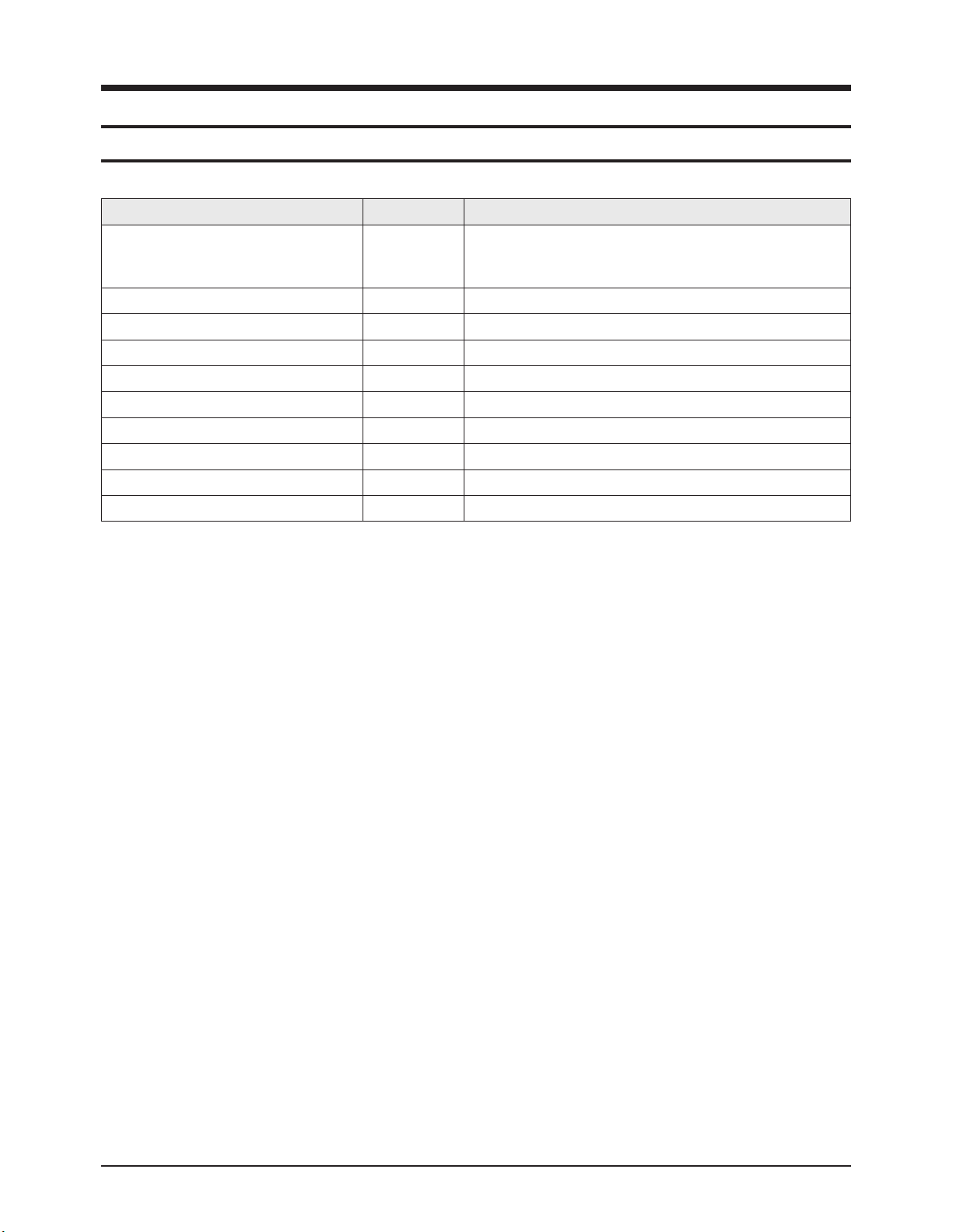
No Assy Code No. Description Major Symptoms
1 ASSY PCB P-SMPS BN96-02213A Main SMPS No power, Blank screen, the Relay repeats On and Off.
2 ASSY PCB P-SMPS BN96-01856A DC-DC SMPS Blank screen, the Relay repeats On and Off.
3 ASSY PDP P-X MAIN BOARD BN96-02032A X Drive Board Blank screen
4 ASSY PDP P-Y MAIN BOARD BN96-02033A Y Drive Board Blank screen
5 ASSY PDP P-LOGIC BOARD BN96-02035A Logic Board Blank screen, Screen noise
6 ASSY PDP P-Y BUFF UPPER BOARD BN96-02034A Y Buffer Upper Board Upper screen is blank
7 ASSY PDP P-Y BUFF LOWER BOARD BN96-02216A Y Buffer Lower Board Lower screen is blank
8 ASSY PDP P-ADDRESS E-BUFF BOARD BN96-02036A Address E Buffer Board Corresponding Buffer Board block screen is blank.
9 ASSY PDP P-ADDRESS F-BUFF BOARD BN96-02037A Address F Buffer Board Corresponding Buffer Board block screen is blank.
10 ASSY PCB MISC-MAIN BN94-00733A Main Board No Power, Abnormal screen for each input source, PIP screen trouble, Sound trouble
11 ASSY FUNCTION BN96-02049B Function Key Board The side function key does not work properly
12 ASSY POWER BN96-02050B Power Button Board The remote control does not work properly, the LED does not work properly.
13 ASSY PCB MISC-SIDE AV BN94-00732A Side AV Board The AV2 and S-VIDEO2 modes do not work properly
Page 47

6-8 Samsung Electronics
MEMO
Page 48

Block Diagram
Samsung Electronics 7-1
7. Block Diagram
7-1 Overall Block Diagram
Image
Scaler
CPU
Decoder
Deinterlac-
er
Y Main Board
X Main Board
1024x768 Pixels
1024x768x3 Cells (R,G,B)
(110V)
Micom
Page 49

Block Diagram
7-2 Samsung Electronics
7-2 Partial Block Diagram
7-2-1 Main SMPS Block Diagram
7-2-2 DC-DC SMPS Block Diagram
TOH
DLOC
tup
nICA
~
V09
V231
I
ME
RETLIF
TUPNI
yrailixuA
egatS
V5_DT
S
langiSyaleR/NO-SP
V
langiSNO-S
DLOC
re
lbuoDegatloV
V
cc
TOH
gnihctiwS_SV
egatS
P
lortnocMW
e
gatS
gnihctiwS_AV
egatS
lortnoCMWP
egatS
tuptuOitluM
gnihctiw
S
egatS
lortnocMWP
egatS
GER
GER
GERREPPOHC
C
GERREPPOH
)V07+(AV
nruteR
1
DLOC
)V002+(SV
nruteR
)V33+(TV
V21+(V21D
)
)V21+(V21A
)V3.5+(V3.5D
R
nrute
)V51+(GV
)V81+(PMAV8
V5.6+(V5.6
)
Vs Input Part Vscan Output
Control
and
Switching Block
Control
and
Switching Block
Control
and
Switching Block
Transformer
Auxiliary
Power
Transformer
Auxiliary
Power
Transformer
Auxiliary
Power
Rectification
Block
Feedback
Block
Rectification
Block
Feedback
Block
Rectification
Block
Feedback
Block
Vset Output
(175~210)
Ve Output
Page 50

Block Diagram
Samsung Electronics 7-3
7-2-3 Module Driver Board Block Diagram
1. Y Main Board
2. X Main Board
Logic Signal Input Part
Logic Signal Buffer
Power Input Part
Logic Signal Input Part
Power Input Part
Logic Signal Buffer
Page 51

Block Diagram
7-4 Samsung Electronics
7-2-4 Logic Board Block Diagram
7-2-5 Main Board Block Diagram
4pin (I2C)
SDA, SCL
LVDS
SIGNAL
10Pin(Power)31Pin LVDS
RELAY_EINT
AC-OFF-EINT
Vs-ON
60MHz
TX, RX
50pin Connector
Y-MAIN
CONTROL
SIGNAL
ADC 4bit
DDR
(FA)
MICOM
R,G,B : 16bit
CLK A, B
BLK, POL, STB
ADC 1bit
60pin Connector 60pin Connector
(ASIC 816P)
CONTROL
SIGNAL
30MHz
SPS-NIRB
74MHz
ASIC
nRESET
DATA : 32bit
ADDR : 12bit
DQS, CLK, nCLK
DRIVE
RESET
DDR
(MA)
DDR
(MB)
X-MAIN
CONTROL
SIGNAL
R,G,B : 16bit
CLK A, B
BLK, POL, STB
28F640
30pin Connector
ADC 3bit
VIDEO1
S-VIDEO1
VIDEO2
S-VIDEO2
(SIDE-AV)
Main
VSB NIM Tuner
Video SW
SVP-EX62
Audio Process
MSP4440K
NSP
Display Panel
42", 1024 x 768
DNIe
Lite
Audio AMP
TAS5122
Optical Out
Coaxial Out
Page 52

Wiring Diagram
Samsung Electronics 8-1
8. Wiring Diagram
8-1 Overall Wiring
ASSY SIDE-AV
ASSY FUNCTION
BN96-02550A
BN94-00732A
ASSY SPEAKER
BN96-01737A
ASSY POWER
BN96-02050B
ASSY PCB MISC-MAIN
BN94-00733A
Page 53

Wiring Diagram
8-2 Samsung Electronics
8-1-1 PDP Module ↔↔SMPS Wiring
①
CN809(Main SMPS)
↔ CN3(DC-DC SMPS)
Pin No Signal
1 ■
5.3V
2 Vg
3 RTN
4 RTN
5 RTN
6 RTN
7 RTN
8 Va
9 Va
10 N.C
11 Vs
12 Vs
②,
CN2(DC-DC SMPS)
↔ CN5003(Y B'D)
Pin No Signal
1 ■
Vs
2 Vs
3 RTN
4 RTN
5 Vset
6 RTN
7 Vscan
8 RTN
9 Vg
10 5.3V
③
CN4(DC-DC SMPS)
↔ CN4004(X B'D)
Pin No Signal
1 ■
Vs
2 Vs
3 RTN
4 RTN
5 Ve
6 RTN
7 RTN
8 Vg
9 5.3V
④
CN5(DC-DC SMPS)
↔ CN2601(F-Buffer)
Pin No Signal
1 ■
RTN
2 N.C
3 5.3V
4 N.C
5 Va
⑤
CN810(Main SMPS)
↔ CN2026(Logic B'D)
Pin No Signal
1 ■
5.3V
2 5.3V
3 RTN
4 RTN
5 5.3V
6 RTN
7 PS-ON
8 N.C
9 VS-ON
10 STB 5V
Page 54

Wiring Diagram
Samsung Electronics 8-3
8-1-2 Main Board ↔↔SMPS, SIDE-AV, Power Button, Function Board, Speaker Out Wiring
①
CN1002(MAIN B'D)
↔
CN804-1(MAIN SMPS)
Pin No Signal
1 ■
FAN-D
2 FAN-ON
3 STB5V
4 RTN
5 PS-ON
6 12V
7 RTN
8 RTN
9 VCA
10 VCS
11 RTN
12 5.3V
②
CN1001(MAIN B'D)
↔ CN803(MAIN SMPS)
Pin No Signal
1 ■
RTN
2 VT(33V)
3 RTN_AMP
4 RTN_AMP
5 18V_AMP
6 18V_AMP
7 RTN
8 12V
9 RTN
10 6V
③
JA9001(MAIN B'D) ↔ CN2077(LOGIC B'D)
Pin No Signal Pin No Signal Pin No Signal
1 ■
12 TXOUT3+ 23 TXOUT1B-
2 GND 13 TXOUT3- 24 TXOUT1+
3 PW_SDA0 14 TXCLKOUTB+ 25 TXOUT1-
4 GND 15 TXCLKOUTB- 26 GND
5 PW_SCL0 16 TXCLKOUT+ 27 GND
6 GND 17 TXCLKOUT- 28 TXOUT0+
7 18 GND 29 TXOUT0-
8 TXOUT0B+ 19 GND 30 GND
9 TXOUT0B- 20 TXCLKOUT2+ 31 GND
10 I2C_READY 21 TXCLKOUT- 32 GND
11 GND 22 TXOUT1B+ 33 GND
④
CN1004(MAIN B'D)
↔ FUNCTION
Pin No Signal
1 ■
KEY1
2 KEY2
3 GND
⑤
CN2001(MAIN B'D)
↔ SPEAKER
Pin No Signal
1 ■
SPK_R+
2 SPK_R-
3 SPK_L+
4 SPK_L-
⑥
CN1003(MAIN B'D)
↔ POWER BUTTON
Pin No Signal
1 ■
GND
2 LED_RED
3 5V
4 GND
5 -
6 SDA
7 SCL
8 IR
Page 55

Wiring Diagram
8-4 Samsung Electronics
⑦
CN101(MAIN B'D)
↔ SIDE-AV
Pin No Signal
1 ■
VIDEO2_CVBS
2 GND
3 VIDEO2_IDENT
4 SVHS2_IDENT
5 VIDEO2_SL_IN
6 GND
7 VIDEO2_SR_IN
8 GND
9 SVHS2_Y
10 GND
11 SVHS2_C
12 GND
Page 56

PCB Diagram
Samsung Electronics 9-1
9. PCB Diagram
9-1 Overall PCB Diagram
No Assy Code No. Description
-
ASSY PDP MODULE P
M1,SPD-42P5HD,D71A,V4,1002× 590,1024× 768,NTSC/PAL,42",PL42AX004A
①
ASSY PCB P-SMPS BN96-02213A SP-R4212,110V(only),370* 245mm
②
ASSY PCB P-SMPS BN96-01856A SPD-50P5HD(DC_DC),200Vin(DC_DC)
③
ASSY PDP P-X MAIN BOARD BN96-02032A
M1,SPD-42P5HD,D71A,V4,1002× 590,1024× 768,NTSC/PAL,42",LJ92-01199A
④
ASSY PDP P-Y MAIN BOARD BN96-02033A
M1,SPD-42P5HD,D71A,V4,1002× 590,1024× 768,NTSC/PAL,42",LJ92-01200A
⑤
ASSY PDP P-Y BUFF UPPER BOARD BN96-02034A
M1,SPD-42P5HD,D71A,V4,1002× 590,1024× 768,NTSC/PAL,42",LJ92-01202A
⑥
ASSY PDP P-Y LOWER BUFF BOARD BN96-02216A
M1,SPD-42P5HD,D71A,V4,1002× 590,1024× 768,NTSC/PAL,42",LJ92-01203A
⑦
ASSY PDP P-LOGIC BOARD BN96-02035A
M1,SPD-42P5HD,D71A,V4,1002× 590,1024× 768,NTSC/PAL,42",LJ92-01270A
⑧
ASSY PDP P-ADDRESS E BUFF BOARD BN96-02036A
M1,SPD-42P5HD,D71A,V4,1002× 590,1024× 768,NTSC/PAL,42",LJ92-01054A
⑨
ASSY PDP P-ADDRESS F BUFF BOARD BN96-02037A
M1,PS42S5S,D,V4,1002× 590,852× 480,NTSC/PAL,42 INCH,LJ92-01027B
⑩
ASSY PCB MISC-MAIN BN94-00733A HPR4272CX/XAC,D71C,SCHUBERT,NON POD
⑪
ASSY BOARD P-FUNCTION BN96-02550A SCHUBERT,CT5000-3690,FUNCTION,BLACK KNOB,500mm,SHIELD
⑫
ASSY BOARD P-POWER & IR BN96-02050B SCHUBERT,CT5000-3540,POWER & IR,CORE
⑬
ASSY SPEAKER P BN96-01737A 8ohm,P5,42,15W
⑭
ASSY MISC P-INLET BN96-02369A HP-R4252,STRAUSS,DOCUMENT,INLET.CORE
⑮
ASSY PCB MISC-SIDE AV BN94-00732A HPR4272X,D71A,SCHUBERT,VE
CN5401
CN5402
CN5403
CN5501
CN5502
CN5503
Y-BUFFER(UP)
5
CN5406
CN5404
CN5405
CN5505
CN5504
CN5506
Y-BUFFER(LOW)
6
CN5006
CN5002
CN5001
CN5005
4
Y-DRIVE
CN5003
CN5004
8
11
SMPS
-DC
2
1
CN800
CN2019
SMPS-MAIN
CN804-1
CN2077 CN2026
7
CN2018
CN803
CN810
CN809
CN3
CN5
LOGIC BOARD
14
CN2075 CN2076
AC-INLET
E-BUFFER F-BUFFER
FUNCTION
CN1
CN2519 CN2603
CN2510
JA9001 CN1002 CN1001
CN1004
CN2604
10
MAIN BOARD
15
SIDE AV
CN101CN102
13
CN2001 CN1003
SPEAKER
CN2601
CN001
12
POWER SW
CN1
CN2
CN4
CN4004
3
X-DRIVE
CN4003
9
CN4000
CN4002
CN4001
Page 57

9-2 Samsung Electronics
MEMO
Page 58

Samsung Electronics
Schematic Diagram
10-1
R1035
0ohm
25
26
27
28
19
20
21
22
23
24
10
11
12
13
14
15
16
17
18
100ohm
R1048
0ohm
R1078
1/10W
MGND1
28
20
21
22
23
24
25
26
27
13
14
15
16
17
18
19
DNVS303EH261A
10
11
12
XREF
XREF
R1037
0ohm
R1049
100ohm
SDA1_DTVCH
SCL1_DTVCH
DRX
CRX
This Document can not be used without Samsung’s authorization.
10-1 POWER & TUNER
10. Schematic Diagram
Power
Signal
2
T
4
01P
5201P
T
2
01PT
6
T
7201P
8201PT
9201PT
8601PT
9601PT
0701PT
1701PT
3701PT
5701PT
8701PT
9
T
70
1P
3801PT
4801PT
5801PT
MS
1
0
9
8
7
6
5
4
3
D
NUOS
2
1
THW 01-052WMS
01N
10
C
PMA_
H
DNGP
V6D
NG
D
2
1
11
0
1
9
8
7
6
5
4
3
2
1
THW 21-05
W
2
20
01NC
V3.3D
V
3.3D
DNG
V21D
P
NO_S
DNG
V5_DTS
D_REHT
DNGP
1_V3.3B
0101L
C
EN106J12CI
FER
X
SCV
X
FER
7
801C
6801
C
u01
F
6
1
V
ACV
Fn001
2
V5
0
6
8
1R
0
I
101C
7
DA
RA
335
M
1
DDV
0A
2
LCS
ATUOV
3
ADS
BTUO
V
4
0
mh
o
NIFER
DNG
W01/
1
CC
V_V5B
3001TF
F
50D87A
IK
1
3
O
I
G
2
1
001T
F
IK
50D87A
F
1
3
O
I
4
C
001
22
F
u0
P
G
N
2001DB
TJ121-
4H1-HH
235
DB
3001
TJ121-2354H1-HH
DB
4001
TJ121-2354H1-H
D
B
V6D
B
A
1
7001DB
B
A
1
2
S006
M
P14
B
L
7
C
201
1
Fu00
1
V6
G
5001C
2
01
F
n0
D
2001TF
1AB
3
1
O
I
G
2
D
P
G
N
OITPO ETELE
N
5001D
S006P14ML
B
2
C
8201
Fu001
V52
C
1
n01
1
2
3
4
C
9201
1
Fn00
V
1
6
D
NGP
7001
6001C
C
01
Fu022
F
n0
DNGP
PF90M87
8101C
7101
C
Fu001
001
Fn
V5
2
P
S
MA_DNUO
0201C
9101C
Fu
Fn001
1
0
1201C
DNGP
20
2
F
1001
CI
ND3851PM
B
S
S
S
NI
NE
PMOC
S
W
B
D
G
F
N
erruC
A3
tn
C
1301
1
0
1
Fp08
Fn001
1
V6
CN
:
P
DNG
20
0
1R
8
mhoK01
7
6
5
R
201
4
hoK
m
0
630
1C
.3
Fn3
DB
1001
P14MLB
A
1
V9B
o
tuA
HGIH : NO
L : FFO
WO
5001L
Hu
22
9101R
mh
oK2.6
W01
/1
201D
4
SS
42
5101D
S006
8414LLMP
B
2
1
C
101
C
Fu74
1
1
6
V6
V
DNGP
.3B
3
0301PT
1
O
NOC_S
C
0
52
R
1
oK6.3
mh
W01/1
4
201C
3201
Fu021
Fn001
V
V3.6
61
C
001
DNGP
NGP
D
B
2101
Fn001
1_V
4701C
3701
001
Fu
Fn
6+
V
7567AB_V5
V8B
_V8
A
1+
B
V33
1_1_V3.3B
V
5.6_S
7301C
2
Fu02
V61
P
DNG
V5_S
7401C
u74
F
V61
2001CI
F50D87AIK
1
3
I
O
G
1C
8301C
01
0
Fn
V61
930
2
4
Fu7
V01
NOC_SO
DNGP
I
4001C
B
PF330A
1
3
I
O
G
C
n001
V61
1C
8401
F
940
2
Fu7
4
V
1
6
C
401C
0
Fn001
V61
UT_V3.
REN
3_S
0501
C
Fn00
1
V61
3
DNGPDNGP
6+
V
B
V21
u22
H
650
1C
Fn001
V
61
9501C
3
tnerruC
A
NG
P
Fn01
6P14MLB
S00
3101DB
1
2
A
B
4601
C
3601C
1
Fu00
01
Fu0
2
V5
61
V
1
SB
2
NI
3
WS
4
D
G
N
5601C
Fn001
V61
C
1
D
001CI
8
ND3851PM
3501
R
8
K01
ho
m
S
S
7
NE
6
C
PMO
5
BF
550
1R
0701
o
mh
K001
Fp08
2701C
Fn3.3
9001L
1501R
mhoK2.6
W01/1
620
D
1
42S
S
7601PT
1
21
.6
6501R
oK6.3
mh
W01/1
NOC_SO
2_V3.3B
1601C
2601C
0
Fu
Fn001
V61
V3
noitpo ASU
2101D
B
06P14MLB
S0
B
A
1
2
4101DB
S006P14MLB
A
1B2
O
no
o A
R
itp
K
E
1C
850
n01
F
1C
60
6
74
Fu
01
V
V61
NOC_SO
2_V3.3B
01R
64
m
0
o
R
7401
m
ho0
AEROK
7001CI
ND3851PM
8
1
2
3
4
7601C
Fn001
C
01
1
S
S
B
S
7
NE
NI
6
W
C
S
PMO
5
NG
B
D
F
1
701C
Fn00
1
V6
1
8
601
Fp0
P
h
N
OITPO ASU
O
N
OITP
1L
800
Hu22
R
2501
mho
K0
1D
520
6
9
01C
42SS
Fn01
1
750
R
mhoK0
1
DNG
DNGP
D
V6
5
101DB
ho001
m
01R
85
F
ERX
W01/1
0
0
1
0601
R
W01/1
6101
DB
6001TF
DNG
P
8001TF
3AFL
0
DNGP
8
7
6
5
1
0
6601R
7601
R
SCV
mho
ERX
F
A
CV
3001Q
G-3261CSK
DN
P
G
FERX
TM322E1A2-03AFL
FERX
TM322E
1A2-
C
S
mho0
X
FER
mho001
X
FER
O
NOI
_ETELED
TP
mh
o
0
6701R
FERX
_WS
OP
01/1
W
1
mhoK
7701R
F
ERX
W01/1
FFO_N
O_NAF
TED_NAF
_VT_4L
V3.3
REW
OP
REW
_WS
C
9701
Fu0
2
2
1C
1
DNGP
V3.3_VT_4ADS
5701C
Fu00
1
9001CI
MGND1
W
M
LT-
K6003-IS
DNG
1
CV
OV
2
1
TUOV
V
N
D
G
3
8
0
0
Fn00
DNGP DNGP
6701C
1
Fn00
DNGP
A
18
T
01P
5
2TU
4
NI
1
8701C
Fu74
V3.6
1
V6
P DNGPDNG
DNG
801C
1801C
Fn001
Fn01
0
V
5
P
A
9801
T
P
1
1
1
6
V
DNGP
UPC_V8.1
R
I
2
3801C
n001
F
V
61
D
L
ER_DE
FER
X
1YEK
X
V3.3
EK
2Y
RX
4801C
5801C
Fu00
F
n001
61
V
P
DNG
NOPMO
200
1A
J
_p9
aj
2
c
k
1
3
2
4
6
5
7
9
8
001A
4
J
3_p6k
caj
1
3
2
4
6
5
01CI
30
A
PF330
B
3
1
I
O
G
1
C
401
2
4
Fu7
V0
1
OC_SO
5
001CI
A
1-D7111PA
8
2
TUOVNIV
1
501C
JDA
Fu7
4
1
V61
0501
R
F
u
74
mho0
V
0
1
W01/1
450
R
1
mho
01
K
W01
/1
FERX
R
5601
hoK0
m
1
FER
FE
TNE
1
300
1PT
1
8
001PT
01PT
70
1
1
900
1P
T
1
11
T
01P
1
T
1
NI_DNGA
D
R
101PT
8101PT
9
1
1
NI_DNGA
N
NGP
OC_SO
N
7501C
1
V5A
Q
K
D
4001D
4101P
2
.8ZLR
101
2
.
2
ZL
8
10
1D
R
N
I_DNGA
01PT
02
1
3201PT
1
2201D
Z
.8
2
LR
GA
R
9201
mho
0
24
01C
01/
W
1
Fn00
1
V61
D
9301R
mho
0
25
01C
W01/1
Fn00
1
V6
1
DNGP
1401R
mho0
1
W01/
4401R
mho0
0
W
1/1
U
0601C
Fn00
V52
3601R
mhoK1
2001
G-3261CS
6001D
001
5
2.8ZL
R
R
2.8ZL
8001C
Fp33
7
2101
R
o
mh
57
4101
3
D
2
.8ZL
2
.8ZLR
2001L
81
9101
1D
D
0
LR
.8Z
2
NI_DN
U
4001
L
2
R
.8ZL
5
101C
Fp03
3
1D
320
.8ZLR
2
N
OITPO AS
L
1
110
NOITPO ETELED
6001L
301
2
C
S
U
7
001L
3401C
1
n00
F
1
V6
GP
NOITPO ASU
HCVTD_6ADS
HCVTD_6LCS
TESERn
NOITPO AS
V
3.3A
2
Fu74
001
Fn
V61
V01
O
NOITPO A
DN
GP
401
4
C
Fu74
V0
1
NOC_SO
DN
35
C
0
1
22
Fu
V
61
RENUT MIN RAEN
NOIT
PO MIN DOP TXE
)NOITPO ETELED(
2401R
3401R mho001
5401R m
O
TSR_4002TXNn
7201D
DS
0007S
4601R
mhoK2
4101R
101R
3
33
mho5
NI_DNGA
3301C
NOC_S
UT
N
D
N
GRENUT
o
h
0
N
O ETELED
OITP
8201D
DS
0007S
0101C
9001C
mh
o57
Fp
p33
F
NI_DNGA
R
6101
8101
R
C
6101
Fp033
O
P
ho0019601R
N
D
1DNGM
2DNGM
N
D
5
GM
6DNGM
NGM
D
7
NGM
D
8
DNGRE
mho001
m
3
DNGM
4DNGM
9201D
0007SDS
4001TF
E1A
2-03AFL
5001TF
03AF
2-
L
001TF
7
L
9001TF
L
01R m
01R
R
01
1
D
1
R
L
Z
074
074
MI
UT
T
M322
TM32
2E1A
322E1A2-03AF
M
mho001
2001R
X
FER
C
ho01
40
R
E
F
X
OC
ho01
60
m
X
FER
1
mho01
FER
X
OC
800
.8
2
FER
X
mho
mho
OC
X
FER
OC
LC_PT
K
1
ATAD_PT
1
_P
NE
T
1
_PT
DP
1
301PT
2
1
3
T
301P
1
43
T
1P
0
1
6301PT
1
7301PT
1
1PT
830
1
9301P
T
1
0401PT
1
1401PT
1
2401P
T
1
3401PT
1
4401PT
1
7
401PT
1
8401PT
1
PT
9401
1
0
T
501P
1
1501PT
1
2501PT
1
3501PT
1
501PT
4
1
5501P
T
1
6501PT
1
5
1PT
8
0
1
9
5
01PT
1
0601PT
1
1601P
T
1
2601PT
1
3601PT
1
4601PT
1
_PT
RRE_ST
1
5601PT
1
6601PT
1
1
1
1
1
DNGREN
NOITPO ASU
XTE_PT
XTC_PT
XTI
_PT
0ohm
0ohm
XTQ_PT
R1035
R1037
DRX
CRX
2PMO
2PMOC
_
2PM
S_
2PM
ES
TNEDI_
Y_2PM
BP_
RP_2PM
I_LS
N
NI_R
C
UT
001
1DNGM
2DNGM
C.N
FR
CGA_
)+B(V5
TFA
TUO_
33
V
DNG
TESER_REWOP
RE
ROR
TUO_OEDIV
.
N
C
TUO_FIS
.3
V3
DNG
V8.
1
1.1
V
/TRATSF
CNYS
V
NE/DILA
DNVS303EH261A
7
AD
AT
6A
D
T
A
5ATAD
4AT
AD
D
3AT
A
AD
2AT
1
AD
T
A
0A
D
T
A
KLC_GEPM
ADS
CS
L
3DNGM
4DNGM
MIN
2
110
2
34
5
6
7
89
11
12
13
14
15
16
17
18
19
20
21
22
23
24
25
26
27
28
RENUT
K
U
TM322E1A2-03AF
T
82x0 : AERO
:
1x0
4
AS
3
V
.3A
NOITPO_ETELED
5
R
9
01
W01
1
/
h
m
2
oK7.
7701
C
Fn1
V
05
4701R
O
C
S
PLA
1DN
GM
M
2DN
G
_N
C
A
G
R
C
F
5+_2B
V
TUO_TF
A
V23+__3B
NG
D
TESER_REWOP
RORRE_GEPM
TUO_OEDIV
FO_LA
X
WS_F
_
T
TUO_FI
S
V3.3+_4
B
DNG
5.2+_5B
V
2.1+_6B
V
CNYS_TKP_G
EPM
E
TAD_G
M
NE_A
P
M
7ATAD_GEP
6ATAD_GEPM
5ATAD_GEPM
4ATAD_GEPM
_G
EPM
3ATAD
GEP
2ATA
M
D
_
1ATAD_GEPM
0ATAD_GEPM
KLC_ATAD_GEP
M
A
DS
C
S
L
3DNGM
4DNGM
RENUT
1R
1
0
6
mho001
W01/1
V5_VT_5ADS
V5_VT_5LCS
601
2
R
mho00
1
01/
W
1
h
m
o0
01/
1
W
M
J
J
N
3001UT
1
2
3
4
K
5
R
1
67
8
925
10
11
R
12
13
14
15
16
17
18
19
20
21
22
23
24
26
27
28
1/10W
DNG
100ohm
100ohm
R1048
R1049
XREF
XREF
SCL1_DTVCH
SDA1_DTVCH
3
2
2
1
D
2301D
NOP
1001A
2
_p9kcaj
1
1
1
3
2
4
6
5
7
9
8
3
001A
3
5101PT
_p6kcaj
1
1
1
3
2
4
6
5
GA
MI
DNGRENUT
NOITP
AERO
O
0
230
6
0
301
ho
08301R
ho
OK
R1078
0ohm
DNGRENUT
3
3
2
1
1
33
301D
1
0
4
1TL6V5C48XZB
B
K
E
E
I_DNGA
mho
m
m
1TL6V5C48XZB
2 TN
01PT
20
1
4001PT
5001PT
6001PT
1
0101PT
1
1
N
R
6101PT
NI_DN
D
1001
D
2101PT
8
.
ZLR
2
9001D
2.8ZL
D
101
Z
R
L
NI_DNGA
71
01PT
1
2
T
01P
2
1
0
02
D
1
.8ZLR
2
GA
N
RENUT MIN RAEN
C
5201
n0
01
F
V52
DNGRENUT
R
0301
mho0
DNGREN
T
U
DNGRENUT
0401R
mho0
OITPO AER
N
3001D
2001
2
.8ZLR
2
LR
.8Z
9001
1001
C
R
C
8001R
m
ho57
D
101
0
1
Z
.8
R
.8
2
L
2
01
mho
Fp33
57
1001L
610
1D
7101
D
3
6201C
R
4301R mho0
001L
2.8
ZL
C
01
31
033
Fp
1201
D
.8
2
R
ZL
NI_DNGA
R
X
NOITPO AER
OK
001DB
8
EN006P23BI
C
B
NOITPO ETELE
FER
1201R
mho0
1
W01/
0301C
V
05
1
Fn00
N
DNG
UT
RE
R
9701
mh
1
0
o0
W0
1/1
X
FER
301
,0301R
2
R
401R,8
301R
0
2.8Z
LR
NI_D
74
Fu
61
V
D
3.3B
NOITPO ETELED
7101DB
8801
C
9801
C
Fu0
1
Fn001
V61
OP
3001
0101R
C
20
Fp33
7
Fp33
mho5
R
101
5
101R
7
101
4
C
Fp033
GA_F
C
4301C
Fu74
05
V
DNG
RENUT
NUT
FF
TX_SPLA
O_LA
NOITPO AEROK
63
1R,
0
701R,87
9
1R,
0
B
4501C
Fu74
1
V6
DNGRENU
T
3_S
2_V
B
2
A
1
NUT_V3.
B
2
A
1
1101CI
0
2
R
CCV
ID
91
/ 1A
EO
1
8
A
1
2
B
71
3A
2B
61
4A
3B
5
1
5A
4B
41
A
5
6
B
3
1
B
7A
6
21
7
A
B
8
11
DNG
8B
OITPO_MIN_D
N
)NOITPO ASU(
V5A
REWOP
01N
3
0
C
THW
52WAMS
80-0
1
2
3
4
5
6
7
8
TL6V5C48XZ
1
NC
4001
30-
2WMS
0
5
1Y
1
2
3
2YEK
2701PT
4701PT
6701PT
7701PT
9
PT
0
4
1
8
1PT
0
0
2
801PT
6801PT
7801PT
2
90
1PT
ho0011
R
m
001
F
ER
X
M
NEDI_1P
1R
50
01R
7001
R
D
7001
.8
2
R
ZL
NI_DNGA
mho074
mho074
9001DB
23BIC
EN006P
B
5301C
D
1
Fn00
V52
DNGRE
TROPWEN MORF
7501PT
A
ENUT_V8.1
R
1
2
1C
5
0
5
Fn001
2
V5
OC
mho01300
E
X
F
R
mho01
F
ER
X
m
o01
h
E
F
X
R
X
FER
FERX
C
NIAM_T
FA
ERX
F
V33B
6201R
mho001
P
1
A
T
OT
SRn
FERX
OITPO ETELE
N
V61
UT
DNGREN
60
01CI
A
81-D711
3
TUOV NIV
JD
1
DNGRENU
T
_1PMOC
Y
BP_
1PMOC
R
P
_1PMOC
_1PMOC
NI_LS
1PMO
NI_RS_
7
756
AB_V5B
01R
22
C
m
1
ho00
001Q
B
E
7201R
mhoK01
W
01/
1
NUT
1DB
010
3BIC
B
6
1C
5401C
40
Fn00
Fu001
1
V
52
2_V3.3B
1101DB
EN006P23BIC
B
8201
R
mhoK
1
W01/1
DNGRENUTDNGRE
2
_V3.3B
EN
006P2
T
3201R
1
m
o0
h
G-3261CSK
W01/1
1301R
mho
0
W01/
1
3301R
mhoK00
1
W01
/1
D
REN
N
U
G
DNGP
E
DNGR
NUT
UT
EN
X
FER
FE
RX
NIAM_SBV
C_R
NI
AM_FIS
RE
8101DB
XCTM542XCL47
1
2
3
4
5
6
7
8
9
01
EROK
1
3
5 6
7
1 2
3 4
5
7
1
3
5
7
1
3
5 6
7
1
3 4
5
7
1
3
5
7 8
TPO A
NOI
2
4
1001A
R
mho33
W61/1
8
2001A
R
mh
3
o
6
3
W6
1
8
/
1
2
4
30
01AR
mho33
6
8
W61/1
2
4
001AR
4
m
3
o3
h
W
1
8
61/
2
5
R
001A
6
mho33
8
W61/1
2
4
6001AR
mho33
6
W
61/1
)7(ST_MAS
S
)7:0(ST_MA
FERX
)6(ST_MAS
)5(ST_MAS
)4(ST_MAS
)3(ST_MAS
)2(ST_MAS
)1(ST_MAS
)0(ST_MAS
C
NYSST_MAS
X
FER
DLVST_MAS
RX
E
F
KLCST_MAS
FERX
)7(NIDOP
(NIDOP
)6
)5(NIDOP
)4(NIDOP
NIDOP
)3
(
)2(NIDOP
)1(NIDOP
)0
(NIDOP
)7:0(NIDO
P
FERX
P
CNYS_NIDO
F
ERX
DLV_NIDOP
FERX
D
NI
P
KLC_
O
FERX
LORTNOC
DNGP DNGP
Page 59

10-2
Schematic Diagram
Samsung Electronics
10-2 SOUND-PROCESS
10uH
10uH
GNDc
61
VDDc
GND_HP_R
63
HPOUT_R
VCC_HP_R
64
VDDIO
53
OUT2B
OUT2A
55
OUT1B
OUT1A
57
GNDIO
58
VDDIO
59
AD
OUT3B
49
50
OUT3A
GNDIO
51
30
AVDPLL
LPPLL
32
AGSPLL
CKIN
24
CKOUT
VDDc
26
GNDc
VDDIO
28
GNDIO
DVDPLL
29
SDATA78/SPDIF_A1)
18
WCK_O1)
BCK_O1)
19
20
SDATA_O12/SPDIF_01)
RESET1)
22
M/S
L2013
10uH
ADR_DA
ADR_WS
I2S_DA_IN1
AVSS
AVSS
62
NC
64
NC
55
ASG
56
SC1_IN_L
SC1_IN_R
57
VREFTOP
58
NC
59
I2S_DA_OUT
60
MONO_IN
61
SC4_IN_R
48
ASG
49
I2S_WS
SC3_IN_L
50
SC3_IN_R
51
ASG
52
SC2_IN_L
53
SC2_IN_R
54
41
NC
42
NC
43
AHVSS
44
AHVSS
AGNDC
46
NC
47
SC4_IN_L
I2S_CL
I2C_DA
19
I2S_CL3
I2C_CL
20
I2S_WS3
21
RESETQ
I2S_DA_IN3
23
DACA_R
24
11
DVSUP
12
DVSUP
DVSUP
13
DVSS
15
DVSS
16
DVSS
I2S_DA_IN2
17
NC
18
NC
ADR_CL
10
10uH
L2012
R2076
0ohm
SGND
This Document can not be used without Samsung’s authorization.
Power
Signal
1002PT
1
CS
S
D
C
PMOC
V
C
PMO
4102CI
2 3
V
TUOV
N
I
DA
J
1
D
NGP
S_V5.2+
Hu0
1
6002L
01
KLC_RL
KLC_S
NI
_ATAD_S
V3.3_VT_5L
V3.3_VT_5A
NI_LS_1OEDIV
NI_LS_1PMO
NI_LS_2
NI_
RS_1OEDI
NI_RS_1PMOC
NI_RS_2
B
A52-D7111PA
5
702C
Hu01
9802C
Fn0
9902R
0012R
2012R
FERX
5012R
X
FER
R
9012
1
FERX
1
61
V
X
FER
V61 5002C
ERX
F
V61
X
FER
V61F
1
FER
X
X
ER
F
V61
V61 2202CF
CCV_V5
02
67
C
22
Fu
V61
C
0902
01
Fu
V
6
1
2C
52
o0
mh
mh
o0
mho0
mh
o0
01
mh
o0
0
KLC_M
TES
PSM
ER
_
V61 Fu01
X
FER
F
u0
Fu01
Fu01
u01 6102C
Fu01
u01
190
Fn001
V
7
012C
001
Fn
V5
2
F
X
R
E
X
FER
00
2
0
2
40
C
1102C
CFu01V6
9102
0
2
02
C
1902
R
mho0
W01/1
C
5802
Fn001
V52
1
V
2
3
4
W
5
B
6
7
8
9
0
1
1
1
1
2
31
41
51
1
6
12R
02
3
C
1002R
mhoK74
4302
R
R
mhoK74
7567AB_V5B
3002
L
Hu
3.3
C
2502
u74
F
V61
GS
DN
6802R
h
01
m
oK
R
4902
m
hoK01
606061
626263
64
58
59
AD
VDDc
GNDc
VDDIO
HPOUT_R
VCC_HP_R
GND_HP_R
L_
PH_CC
L_TUOPH
NG
L_PH_D
)1M_KC
C
)1M_K
)1M_FIDPS/21ATADS
)143ATADS
)165ATADS
SDATA78/SPDIF_A1)
171718
WCK_O1)
19
BCK_O1)
SDATA_O12/SPDIF_01)
20
212122
N
RESET1)
N
CKIN
M/S
232324
O
I
DDV
NG
OID
V/LCS
H
LV/ADS
cDDV
c
DNG
)1A_KCW
)1A_K
CB
mh
o0
mho0016112R
10uH
R
mho06
mho08202
mho0
49
50
ASG
SC3_IN_L
SC3_IN_R
_AQ_G0444PSM
DVSS
DVSS
DVSS
16
4
NGS
Fn3
3
V
52
C
4
u7
F
V3.6
7102
0202R mho0
48
47
SC4_IN_R
I2S_DA_IN2
17
18
D
0112C
Fu3
PO ETEL
2002DB
9002
R
454546
NC
SC4_IN_L
I2S_CL3
NC
19
20
902C
NOIT
CCV_V5B
DB
4102
mh
o7.4
W01/1
mho0
44
AHVSS
AGNDC
005_21C
I2S_WS3
RESETQ
21
2
6902C
8902C
01
43
222223
0
8002
R
2
1
2
3
4
5
6
7
8 9
D
GS
N
41
42
NC
NC
AHVSS
_LPAC
M
CS
S
RV
S
CS
N
N
D
N
D
_ACAD
I2S_DA_IN3
NCNCDACA_R
24
9702C
u0
00
F
1
V5
2
Fn00
1
Fn00
1
001
Fn
1
4012C
F
n
1_1_V3.3B
1102
W01/1
hoK
m
M
0
KL
CM
V
L
UODS
T
D
NG
V
D
KLCS
KCRL
8
302C
Fu7.4
V53
04
02C
Fn001
04
PUSVHA
93
A_LPAC
83
L_TUO_1
73
R_TUO_1C
6
3
1FE
53
L_TUO_2C
43
R_TUO_2
33
C
23
C
13
BUS_MCA
0
3
C
92
L_MCAD
82
R_MCA
72
2FERV
62
L
5
2
S
0802C
Fn001
R
1
1
R
1
2112R
CV_V5B
C
R
R
DB
V
CCV_
5B
1
2102R
02C
W01/1
m
2
hoK
2002CI
ZC-0435SC
Z
1
1M
+TL
IF
D
NG_FER
A
V
RNI
A
QV
LNI
A
TSR/
402C
6
1
Fu0
V61
01
Fn001
V52
6
51
41
31
21
11
01
C
3202C
Fn001
V52
2C
440
3402C
.1
V61
Fp0
Fn5
74
0502C
Fu01
V6
1
Fn2.2
C
5102
05
V
Fn2.2
C
8102
V05
4202
C
5202
2302
R
u1
F
F
u1
V05
V05
W01/
1
3402R
mho001
V8
B
5402C
200
2L
Fu001
H
u3.3
1
002D
25TZB
51C-
2212R
3212R
DNGS
9402R
0502
R
4502R
mho001
mho0017502R
1202R
2202R
oK0
mh
01
mhoK001
W01/1
W01/
1
3302R
mhoK001
mhoK001
W01/
1
PSM_TESE
R
N
OITPO ETELED
mhoK001
W01/1
SGND
mhoK001
W01/1
7402
mho
Fu01
C
001
mho001
E
F
X
R
FE
RX
Fu011502C
FE
RX
F
ER
X
_ROTINOM
A
2CS_Y
N
1_KLC_S
T
UO_LS
TUO_RS_ROTINOM
UO_LS_
T
TUO_RS_2CS_YNA
3
2
1002TF
W01/1
mh
o001
FERX
3202R
D
D
CV5
02C
41
Fu001
V
61
02R
42
0
mho
1
0
1
W01/
2C
120
Fn001
52
V
02R
24
mho001
1
W01/
2C
920
Fn001
2
V5
5402R
1
mho00
1
W01/
2C
430
Fn001
2
V5
02R
64
1
mho00
1
W0
1
/
2C
240
01
Fn0
V52
1YALE
2YALE
4002CI
)LEER(DA361
F47
61
1
2
51
3
41
Q
D
0
0
31
4
1Q
D
1
21
5
2D
2Q
6
11
Q
D
3
3
1
7
0
8
9
5002CI
1
2
3
4
5
6
7
8
1
2
3
4
5
6
7
8
1
2
3
4
5
6
7
8
ERX
F
FER
X
)LEER(DA361F47
61
1
5
41
D
Q
0
0
1
3
1Q
1D
21
Q
D
2
2
11
3Q
D
3
01
9
8
002CI
)LEER(DA361F47
61
51
41
0Q
0D
31
1D
Q
1
21
2D
2Q
11
3Q
3D
01
9
9002CI
F47
)LEER(DA361
61
51
41
Q
0
0D
3
1
D
1Q
1
21
2Q
2D
11
Q
3D
3
01
9
le
D
15
2502R
02R
mhoK1
mhoK1
eteleD
160
0602R
2R
mhoK1
mhoK1
02R
FERX
1_KLC_S
MARS M
1
ete
le
D
740
2R
8402R
te
e
mho051
mho051
4602R
mhoK7.4
YALED OIDUA
ETELE
9002R
8102
R mho00
0302R
mho001
TUO_ATAD_
V
C
502C
9
001
Fn
V52
ITPO
1
15102R
ho00
1
X
D
7102C
Fn001
V52
mho00152
7
002CI
1
1A
9A
8A31
31A
_E
W
2S
C
51A
C
CV
CN
61A
41A
2
1A
7A
6A
5A
4A 3A
55FT-D2C8001X6K
23
_EO
13
1A
0
0
3
_SC
92
8O/I
8
2
7O/I
72
6O/I
62
5O/I
5
2
4O/I
42
SSV
32
3O/I
2
2
2O/I
12
1O/I
02
0A
9
1
1A
81
2A
7
1
1
2
4
5
6
7
8
9
01
1
1
1
2
31
1
4
1
5
1
6
S
5
0102CI
D
521F47N
1
NI
N41A
1
3
2
I
N
M
B
2
1
3
I
N
L
C
11
4
NI
K
D
01
5
I
N
J
E
6
9
I
N
I
F
7
NI
8
G
H
5602R
mhoK7.4
3502R
mhoK1
6502R
mho051
9502R
mhoK1
8502R
eteleD
mhoK1
102
NO
mho00
m
FER
S
KLC_
S
1_KLC_
DNG
H
L_P
R_PH
0702C
6602C
7602C
Fn7.
Fn7.4
4
9602C
8602C
Fn
Fn3.3
1
Fn1
DNGS
A_V81+
7702
C
Fn01
02R
9
2
3.
3
PMA_DNUOS
7902
PMA_DNUOS
1012R
PMA_D
S
NUO
4012
DNU
PMA_
OS
PMA_DNUOS
1802C
01
V
52
1
1
1 2
1 2
C
Fu00
001
7002L
2
9002L
2
1
02L
1
4102L
9602R
2602C
mhoK02
Fu1
1702R
5602C
m
hoK02
Fu1
_V81+
A
02C
87
01
Fn
2802
F
n
R
3902
3.3
e
D[
le
R
1702C
F
u01
V61
R
TUO_ODS_MAS
R
TUO_KLCRL_MAS
TUO_KLCS_MAS
TUO_KLCDO_MAS
NO
PO
T
I
et
]
0602R 9502
C
2702
1
Fn00
2802
m
ho0
4
802
mho
0
7802R
mho0
0902R
0
mho
2502R 1502R 8402R 7402R
602R
2R
60
7
1
m
9702R
hoK1
1
V3.3B
_1
_
5002L
3102
CI
2RTD442CHV47CM
02
CCV
91
O
2E
81
0O
71
4
I
61
1
O
51
5I
41
O
2
31
6I
21
3O
11
7I
1
NI
O
1E
2
N
I
I
0
3
NI
4O
4
I
N
I
1
5
N
I
5
O
6
NI
2I
7
I
N
6
O
8
NI
3I
9
NI
7O
01
I
N
D
N
G
C
1002
Q
B
G-
3261CSK
E
mho0
0
mho
ho0
m
mh
o0
M
M
M
PMA_DNUOS
+L_
KPS
8902R
3902C
Fn001
C
1012
1
C
01
7012R
1
Fn00
1112
1212R
Fn001
112C
7112R
4
Fn0
4902C
mhoK01
Fn01
3
R
012
1
8012R
1
mhoK0
S
12C
m
hoK01
n
01
5112R
1
8112R
m
1
hoK01
C
1
0
C
9902
V
36
3
3
Fn0
PMA_DNUO
3012C
Fn01
21
F
36
V
33
0
PMA_DNUOS
5112
Fn
2002D
-L_KPS
+R_KPS
3112C
Fn
5002
D
R
1-ETZL
-R_KPS
30
02D
B0311-ETZLR
B0311-ETZLR
PMA_DNUOS
4002D
B031
S
B0311-ETZLR
NUO
PMA_D
0
0
L
8
2
2
3
4
1
0102L
2
3
1
4
L_TUO_REKAEPS
+L
2002PT
4
3
2
1
1
-L
3002PT
1
4002PT
+
1
R
5002P
T
-R
1
THW 40-052WAMS
1002NC
R_TUO_REKAEPS
NOITPO
]eteleD[
R 9
R 0
102
1
002CI
M
1
TUPTUO
2
QI
3
D1
4
D2
5
Q
2
6
Q3
7
D3
8
D4
9
Q
4
01
DNG
6002CI
M
1
TUPTUO
2
QI
3
D1
4
D2
5
Q
2
6
Q3
7
D
3
8
D
4
9
Q4
01
DNG
ERX
F
F
ERX
5502R mho0
2R
760
eteleD
1_1_V3.3B
0802R
mhoK1
W01/1
1802R
3802R
_IMD
H
5802R
8802R
NI_KLCM_PS
CS_PS
NI_KL
NI_KLCRL_PSM
NI_ODS_PS
0
4
2DB
0
A
B
1
2
B
5002D
A
B
1
2
002D
6
B
A
B
1
2
PMA_DNUOS
0
302R 8102R 5102R 9002
1
302
V
C
XCTM373CH47M
02
CCV
91
Q8
81
8
D
71
7
D
61
7
Q
1
5
Q6
41
6
D
31
D5
21
Q5
11
XCTM373CH47M
02
CCV
91
Q
8
81
8
D
71
D7
61
Q7
51
6
Q
41
6
D
31
D5
21
5
Q
11
O
mho0
NG
R
R
102
HCTAL
HCTAL
1102CI
D41F47CM
4
1
1
CCV
OI
3
1
2
5
I
O_O
2
1
3
5_O
1I
4
1
1
4
1_O
I
0
1
5
4_O
2I
6
9
3
2_
I
7
8
3_O
D
NOITPO ETELED
ho001
0102
m
o001
mh
6102R
9
ho001
m
ho0011302R
m
05
2R
440
FERX
m
ho001
W01/1
2302C
Fu01
001
V61
V5
2
5
CV
602C
0
n001
F
V5
2
5
2102C
Fn001
V52
202C
p74
F
V
KLC_S
1302C
Fn
3102C
Fu0
1
V61
FER
X
6
CV5
1_
NI_ATAD_S
WOL HGIH S2I_LES
PTUO
KLCM_IMDH
KLCS
KLCRL_IMDH
ODS_IMDH
D
NGS
LG
A
E TU
S2I_LES
IM
DH E
S
DNG
NI_D
NGA
3102
m
hoK
W01/1
56
57
SC1_IN_R
ADR_DA
8
9
R
2DB,7002D
1
_1_V3.3B
202R
R
55
ASG
SC1_IN_L
0
ADR_WS
ADR_CL
10
5902
C
5012C
12C
PMA_DNUOS
1
7202R mho
9202R
53
54
SC2_IN_L
SC2_IN_R
DVSUP
DVSUP
11
12
DNGS
mho01
8802C
Fn33
5902
Fn33
C
90
Fn001
02C
52
13
3
ED : 900
80
Fn00
0
51
ASG
2102CI
08X
DVSUP
141415
602C
2012
Fn33
Fn001
B
8B
02C
2
10
002C
01
Fn
Fu22
0
1
2002R
3002R
4
mhoK74
mhoK7
6302R
5302
4
mhoK74
mhoK74
3502C
Fu2
2
Fn74
6002R
5002R
4002R
hoK74
m
mhoK74
8
302R
7302R
mhoK74
mhoK7
5502C
4502C
Fn5.1
8002R
7002R
m
4
m
hoK7
hoK74
9302R
mhoK74
3002CI
M2504CH47MM
61
1
Y
0
DDV
2
51
X2
Y2
41
3
M
OC
X
-Y
1
31
4
Y3
X
MOC
-
5
2
1
Y1
X0
11
6
NE/
3
X
7
01
EE
A
V
9
8
SSV
B
402R
R
0
1402
m
4
mhoK74
mhoK74
hoK7
NI_LS_IVD
X
NI_RS_IVD
_LS_
P
NI
C
_R
P
S_C
6
502C
Fp074
_FI
S
Fp658402C
X
FER
N
IAM
X
NI
Fp6
02C
594
O
S
OS
FER
F
RX
E
FER
ERX
F
V6
1LES_DNU
2LES_DNU
Fp657502C
502C
/94-
CH
234R81_H5MS
F
ERX
KLC
_M
8
1002X
Fp3
DNGS
1 2
1602C
Fp
ho0012602R
3
m
B
CCV_V5
Hu3.3
4002L
3602C
Fu01
V61
_5ADS
DNGS
S
1426_V3.3+
3002DB
M
3702
C
1
F
9802R
m
01
hoK
n00
4702C
Fu01
1
V6
1_1_V3.3B
A003S2102ZP
V3.3B
A1TUO_1426
1
6
B1TUO_
2
4
A2TUO_1426
B2TUO_1426
C
7802
Fn0
01
V5
2
525253
545455
565657
GNDIO
OUT1A
I
102C
6PS
x0
CKOUT
VDDc
252526
10uH
L2012
6112C
Fn001
49
50
51
OUT3B
OUT3A
VDDIO
GNDIO
OUT2B
OUT2A
OUT1B
6
1426PS
A142
CC
GNDc
VDDIO
GNDIO
DVDPLL
30
272728
29
C
V61
84
A4TU
O
74
O
B4TU
64
V
OI
DD
54
O
IDNG
4
4
UO
A5T
3
4
B5TUO
24
OIDDV
14
OIDNG
4
0
A6TUO
3
9
B6TU
O
8
3
DDV
c
73
DNG
c
63
)1TCETORP
3
5
NETSET
3
4
LLPSVD
3
3
A
PSV
LL
AVDPLL
LPPLL
AGSPLL
313132
8012C
Fn22
10uH
10uH
L2013
8112C
00
1
Fn
7112
Fu01
+
0012C
Fn001
52
V
9112C
Fn001
61
V
1426
_V3.3
6
012R
4
mhoK
7.
3112R
mho0
O ETELED
NOITP
0212C
Fu01
0
12R
1
1
mho00
9
112R
1ETUM_PMA
1
FER
X
C
mhoK0
B
E
PSM
CS_
M
PSM
1_1_
4802C
Fn001
6802C
Fu1
R
6902
7902C
1
Fn00
mho0011112R
1426_V3.3+
4112R
1
Q
2002
G-3261CSK
L
3602R mho001
S
TAD_S
M_TESER
I_KL
m
ho001
mhoK0
u1
V
1002
V
61
V61
Fu01
Fu01
202C
7202C
8
C
CV_V5B
7002
6002
F
n001
_MAS
MAS
5
302C
6302C V53
1002DB
7002
C
Fu74
V3.6
R
74
TUO_KLCDO_MAS
NI_ODS_MAS
N
I_KLCS
TUO_KLCS_MAS
TUO_KLCRL_MAS
NI
_KLCRL_
V533302C F
u7.4
V53
Fu7.4
F
u7.4
DB 9002
C
7302C Fu7.4V53
9302C Fu
01
1402C Fn00
1
DNGS
mho0016602R
1
5_VT_5LCS
V
V
5_VT
KLC_
KLC_RL
U
O_ATAD_
T
NI_A
S
P
N
NI_KLCRL_PS
NI_ODS_
602R
8
mhoK
FERX
FERX
F
X
R
E
FERX
4702R
FERX
R2076
NOITPO ETELED
0ohm
FERX
87
02R
X
FER
RX
FE
FERX
FERX
PMA_DNUOS
1
2
3
4
5
6
7
8
9
01
11
21
31
41
51
61
71
81
91
02
12
22
32
42
52
62
72
82
6012C
F
62
636364
58
59
61
60
NC
NC
NC
AVSS
AVSS
PUSVA
6
5
66
6
7
6
8
NA
6
9
7
0
17
7
2
PT
7
3
7
4
N
7
5
7
6
77
D
7
8
7
9
8
0
DNGS
10702R
12702R
MONO_IN
PUSVA
NETSET
NI_LATX
C
CN
RDA
BDNATS
1
mh
o00
VREFTOP
+1NI_ANA
-NI_ANA
+
2NI_A
TUO_LATX
TUO_LC_DUA
1_O/I_RTC_D
0_O/I_RTC_
LES_
QY
I2S_DA_IN1
I2S_DA_OUT
I2S_WS
I2S_CL
I2C_DA
I2C_CL
NC
7
6
5
4
3
2
mho00
mho0013702R
1
mho00
2R
1
m
ho001570
mho0017702R
mho00
3802
C
Fn001
PMA_DNUOS
5102CI
CDI22
A
15SAT
G
D
N
DN
G
GERG
DDVD
D
NG
D
NG
D
NG
D
PA_
MWP
MA_MWP
MB_MWP
P
B_MWP
G
D
R
E
1M
2M
3M
NTR_GER
PC_MWP
M
C_
MWP
T
R/
ESE
M
D_MWP
P
D_MWP
S/
BA_D
D
C_
D
S/
TO/
W
GERG
DNG
D
NG
65
DNG
55
DDVG
45
A_TSB
35
A_DDV
P
25
P
A_DDV
15
A_TUO
05
A_TUO
94
DNG
84
DN
G
74
BA_TESER/
B_TUO
64
B_TUO
54
B_
P
DDV
4
4
B_DDVP
34
TSB
B_
24
C_TSB
14
C_DDVP
04
C_
P
DDV
93
C_TUO
83
C_TUO
73
DC_
DNG
63
DNG
53
D_TUO
43
D_TUO
33
D_
DDVP
23
D_DDV
P
13
B
D_TS
03
G
V
DD
92
DNG
PMA_DNUOS
Page 60

Samsung Electronics
Schematic Diagram
10-3
10Kohm
R3037
L3006
10uH
10Kohm
R3015
R3016
10Kohm
R3141
10Kohm
R3001
2.7Kohm
10Kohm
R3007
10Kohm
R3017
R3032
10Kohm
4.7Kohm
R3138
10Kohm
R3004
10Kohm
R3011
10Kohm
R3010
2.7Kohm
R3002
R3134
4.7Kohm
R3022
10Kohm
R3020
2.7Kohm
10Kohm
R3038
R3018
10Kohm
R3019
10Kohm
10Kohm
R3014
10Kohm
R3003
R3036
10Kohm
R3013
10Kohm
10Kohm
R3012
R3009
R3008
10Kohm
10Kohm
10Kohm
R3021
10Kohm
R3005
R3082
1Kohm
10Kohm
R3035
VCC
GND
1Kohm
R3084
1Kohm
R3081
XREF
1Kohm
R3083
R3085
1Kohm
R3006
10Kohm
R3034
10Kohm
43
P1.7/CSYNC-I(SOG)
HSYNC-I(2)
44
P3.3/PWM3/SDA1(2)
P3.4/PWM4(2)
37
P3.5/PWM5(2)
P3.6/PWM6(2)
38
NC
39
40
P1.4/VSYNC-O
P1.5/HSYNC-O
41
P1.6/CLAMP-O
42
34
P3.2/PWM2/SCL1(2)
35
VDD2
22
VSS2
P0.4(2)
15
P0.5(2)
P0.6(2)
16
NC
18
P1.0/AD0
P1.1/AD1
19
P1.2/AD2
20
P0.3(2)
12
NRESET
13
10Kohm
R3039
R3033
10Kohm
PC_HS_MICOM
PC_VS_MICOM
PC_VS_MICOM
10-3 MICOM & IO-EX & AV IN/OUT
This Document can not be used without Samsung’s authorization.
Power
Signal
XREF
S
0103CI_
5A
V
5003C
Fn001
A
DS_UME
LCS_U
ME
003N
2
C
P
H
D
CDD
1
3204-82-22
2
FERX
V5_C
F
ER
X
V5_IM
C
CV_
DK
W_CDD
W
XREF
6203R
mho0
1003C
I
X8K5213DBW7CN
8
7
6
5
2003D
481S
1
/
C
1EO
V
C
2EO/
A1
B
1
A2
N
2
D
B
G
1
2
2
3
P
FERX
003Q
2
UME_ADS
2
UME_LCS
3
4
V5A
1
3003D
3
481SDK
9603R
mhoK7.4
C
B
E
Y-3261CSK
3
103C
Fu22
V
61
CS
MS_3L
R
6803
1
mhoK0
3
Z
4103C
2
001
Fn
1
1_V3.
3B
R3134
4.7Kohm
R
I
R
X
FE
MOCIMS_3ADS
FERX
MOCI
V5A
6403
R
R
2003X
2,H5MS/94-C4
42
zHM0.
C
0103
22
V05
A
6003D
V5C48XZB
2
Fp
5
V
3.3
3
2
1TL6
1
PC_HS_MICOM
PC_VS_MICOM
1_V3.
4203R
8203R
1 2
3 4
5 6
7 8
1 2
3 4
5 6
7 8
4403R mho00
7403
0503R
2503
0603
1TL6V5C
48XZ
8003DZ
1
2
3
3B
10Kohm
10Kohm
10Kohm
10Kohm
10Kohm
R3007
R3011
R3010
R3009
R3008
mho00
1
mho0
0172
mho00
1
1
mho00
W61/1
1
W61/1
mho0012403R
1
mho001
mho00
1
1
mho00
mho0015503
mho0018503R
mho001
1TL6V5C
9003DZ
1
2
3
1YEK
FERX
2YEK
FER
X
R
DER_DEL
NRG_DEL
R
4903
mho0
01
X
5903R
NOITPO ETELED
mho0
01
V3.3A
1003
C
Fu01
38
NC
NC
P3.5/PWM5(2)
P3.6/PWM6(2)
2003
B668F3S
P1.0/AD0
P1.1/AD1
19
363637
35
P3.4/PWM4(2)
P3.3/PWM3/SDA1(2)
VDD2
P1.2/AD2
212122
20
V61
34
/0.3P
P3.2/PWM2/SCL1(2)
P
P
P
P
P
P
/3.1
VSS2
R
R
PC_VS_MICOM
43
44
39
40
41
Fn1
1403
C
V0
5
1
2
mho001
1303R
FERX
03R
R
mho00
1
mho0019403
FP61,ZHM4
1103C
Fp2
V0
O ETELED
DZ
7003
B
04
1403R mho001
3403
3
1
mho00
4
mho001
5
6
7
8
9
1
N
OITP
1TL6V5C48XZ
42
HSYNC-I(2)
)2
(I-CNYSV
P1.4/VSYNC-O
P1.6/CLAMP-O
P1.5/HSYNC-O
0
0.0
TNI/
P
P1.7/CSYNC-I(SOG)
1TNI/1.0
P
(0AD
ADS
S/)1(
)2
T
(0L
)2
CS/)1(KLCS
CI
1DDV
SSV
1
TUOX
NI
X
01
T
TS
E
1
P
PAC2
MT/2.0
P0.3(2)
P0.4(2)
P0.5(2)
P0.6(2)
NRESET
141415
16
171718
12
13
2.7Kohm
10Kohm
2.7Kohm
10Kohm
10Kohm
10Kohm
R3001
R3004
R3002
R3003
R3005
R3006
03R
R
1003A
3
3
1MWP/1.3P
3
2
0MWP
3
1
7.2
3
0
6.2
92
5.2P
2
8
.2P
4
2
7
.2
3
2
6
2.2P
2
5
1.2
42
0.2
2
3
3DA
mho001
7803
8803R
01
mho0
mho0019803R
mho001
2903R
1
3903
mho00
2003AR mho00
R
R
R
R
B
48XZB
F
ERX
FE
RX
10Kohm
R3013
FERX
FER
10Kohm
10Kohm
R3014
R3012
mho0010903R
mho0011903
CS
V3.3A
10Kohm
10Kohm
R3015
R3016
10Kohm
10Kohm
R3017
R3018
652C42_2L
652C42_2ADS
O ETELED
10Kohm
10Kohm
R3019
R3021
V3.3A
2TA
8
7
6
5
NO
ITP
10Kohm
R3022
Fn001 21
C
CV
/
CW
LCS
ADS
2.7Kohm
R3020
1003PT
1
2003PT
1
3003PT
1
4003CI
C
N
CN
C
N
SS
V
V3.3A
3203
R
m
01
F
ERX
_ET
PH
UM
F
ER
X
X
FER
FERX
FERX
X
FER
X
FER
R
FE
X
X
FER
X
FER
ERX
F
FERX
F
ERX
ERX
F
ERX
F
F
ERX
FERX
ERX
F
FERX
03
C
7.2-IS01-NA61C4
1
2
3
4
1ETUM
_PMA
2ETUM_P
MA
TNEDI_P
H
TNEDI_CP
TNEDI_2PMO
C
TNEDI_1PMOC
SHVS
TNEDI_1
TNEDI_IMD
H
TNEDI_1OEDIV
OFNI_REWOP
PVS_TESER
NE_SDVL
IMDH_TESE
R
TED_NAF
FFO_NO_NAF
PSM_TESER
REWOP_WS
YDAER_C2I
hoK
203R
9
C
B
mhoK01
CSK
E
2403
C
22
Fu
V61
mho05203R
W
01/1
1003Q
G-3261
TESERn_UPC
E O/I
A
V5
R3138
4.7Kohm
D_WS
H_W
S
S
1
9313R mhoK0
9003Q
ESER
S
G-3261CSK
S
2I_LES
C
R
GA_F
N
_TFA
IAM
A1B
C
O_VT
PMOC_LE
1003T
F
2
2003
003
3
C
Fn001
Fu01
V52
V61
FE
RX
TU
FERX
TUO_CDA_IMD
F
ER
X
TUO_FIDPS_W
X
FER
EIND_T
F
ER
X
F
ER
X
CP_PMOC_LES
X
FER
FER
X
FERX
R
6703
mhoK1
03R
703R
87
7
m
1
mhoK1
hoK
1003X
94-CH
8003C
2
1Q
6503
R
603R
1
R
R
5603
7603R
0703R
2703R
4703R
X
21(DMS-S/
9003C
Fp0
0Q
2
3
4
mho0
743503R
5
6
mho074
7
mho0
01
8
743603
mho0
9
mho001
01
mho001
11
ho001
m
21
mho00
1
31
4
1
mho001
51
61
NAP
)mpp03,zHM
CI
3003
SSV
0
26x
NIX
TUOX
P
E
PV_TS
T
P
P
3
P
P
P
P
P
SVA
P
O
S_1_0
P
KCS
_0_0
P
TESER
0P
_
0
2
_3P
0_2
0D
A_
_
1_2
1DA
P
2
DA_2_2P
3DA_3_2P
3_1
NI_
P
4
A_4_2
D
_2
A_6_2
5DA_5
P
S
RE
D
ETELE
10Kohm
10Kohm
R3036
R3035
10Kohm
10Kohm
R3037
R3038
NOITPO
10Kohm
R3039
10Kohm
R3141
R
1Kohm
R3081
1Kohm
R3082
1Kohm
1Kohm
R3084
R3083
1Kohm
R3085
NOITPO ASU : 1413R,3703
FE
RX
1NE
F
ER
X
E
0N
FERX
D
E
F
X
R
F
ERX
X
F
ER
E
F
X
R
FERX
FERX
FERX
FER
X
X
FER
FERX
X
FER
1YALE
2YALED
O
LES_BO
WS_DOP
O_ANL
N
S
1FR
_W
2FR_WS
NE_BO
O
RI
Q
SYS2
UT
ATS_NAF
S
5_VT_5LCS
V
S
V
D
5_VT_5A
D
10Kohm
10Kohm
10Kohm
8T0S-53X8249C3S
31
2
DDV
5403R
3
1
S_2_0
I
P
OL
C_3_0P
8DA_4_0
9DA_5
_0
01DA_6_0
P_11DA_7_
0MW
1
_3P
P
3_3
DCZ_0T_0_1P
ZUB_1_1
I_2_1P
0TN
_1T
1MWP
KLC
DA_7_2P
S_7
TAD
D
S_6
FERVA
4
8403R
3
0
1503R mho001
2
9
1
4503R mho00
2
8
7503R
72
9503R
2
6
R
2
5
2
4
1
6603R
2
3
R
8603
2
2
R
1703
2
1
3703R
2
0
91
9703R
1
8
1
0803R
1
7
R3032
R3034
R3033
ho074
m
ho07
m
ho074
m
mho074
mho0012603
mho0014603R
mho00
ho074
m
mho001
mho001
mho0015703R
mho001
m
hoK
I
5003C
.T/SA4381SD
R
8
3
R
0
E
BUS
R MOCIM
R
J
2003A
b_p9kcaj
1103PT
0
T
103P
1
1
1
1_DNG
3
2_GIS
2
1_GIS
4
G
2_DN
6
4_GIS
5
3_
GI
S
7
3_DNG
9
6_GIS
8
5_GIS
9003PT
1
2
T
03P
1
1
5103PT
1
7
T
03P
1
1
3D
600
2.8
LR
Z
NI_DNGA
1
mhoK0169
NI
3.3
V5
NI
V
2
W01
/1
TES
7
TSR
_V5/
V3.3/
TSR_
3
6
5
V
LOT_
L
V3.3
OT_
4
5
DNGTSRBP/
1013
mho0
W01/1
3L Hu3.3
200
003D
8
7
003D
211
ZLR
ZLR
2.8
2.8
1103D
ZLR
2.8
NI_DNGA
3R
ho57
m
2103D
3103D
ZLR
2.
2.8
8ZLR
7903R
mhoK2
.2
W01/1
9903R
0013R
mho0
o0
mh
W01/1
/1
W01
L
3003
4003L
2
203C
Fp001
C
8903R
4003PT
1
mho00
1
C
5103
1
Fn0
V
05
6
003CI
0413R mho0
LS
W01/1
TNI_EVA
1 TUPNI VA
D_D
ERX
F
mho0018013R
V
FERX
V
FERX
mho0019013R
IV
X
FER
mho001
1
113R
4203C
9003D
Fp033
2.8ZLR
3203
Fp033
N
_DN
I
GA
I
V
OED
TNEDI_1OEDI
BVC_
S
1OEDI
NI_LS_1OED
1
NI_RS_
XR
8103C Fn001
n0011203C
013R
o012
FERX
TENYNA_DXT
4013R mho01
X
BED_DXT
FER
U
G
5013R mho01
FERX
TENYNA_DXR
GUBE
017
013R
o
F
ERX
V5A
1003L
6103C
Fn001
EWCE232XAM
6
1
1
+1C
2
VCC
3
4
F
5
mh
1
1
01
21
mh
9
+V
-1C
6
-V
+2C
-2C
1
NI1T
UO1T
T
7
T
T
TUO2
NI2
1
U
NI1R
O1R
T
NI2R8TUO2R
GND
51
7103C
Fu01
V61
9
103C Fn001
0203C
Fn001
YNA
3013R
4
3
013R mho001
mho001
6
113R
0
m
ho001
1
13R
3
m
ho001
4003
D
HTG03C3SDC
GA
NI_DN
4203
D
HTG03C3SDC
VRES & TENYNA
F/I TEN
1
1
5003
D
C
HTG03C3SD
NI_DNGA
T
/I ECIVRES
F
1
1
D
0103
HTG03C3SD
C
NI_DNGANI_DNGA
/
I ECI
F
J
5003PT
7003PT
1
1
8003PT
3103PT
NI_DNGA
1
1
6
103P
8103PT
NI_DNGA
1003A
6003PT
L
PUS
AVL
4
9
0
1
5
6
8
7
3003AJ
4103PT
S
LAVLPU
4
9
01
5
6
8
7
O
P
CIT
1003PO
0782-0005TC
1234567
1
1
1203PT
0203PT
NI_DNGA
7203C
Fn001
NI_D
NGA
D
S LA
P
9103PT
1
03PT
2
2
1
1
3
6303C
2
Fu01
6
V
1
NI_DNGA
U
T
O FI
CCV_V5
B
2003TF
A
0
2
GS
2-4
1F
M
1E
3
R
D
WOL HGIH S2I_LES
IM
ELGAE TUPT
UO
U
_MAS
O_FIDPS
T
DPS
H
FI
_IM
D
S2I_LES
TUO_FIDPS_WS
5212R
212
4
mho0
W01/1
mhoK7.4
W01/1
7003CI
M751SL
D
47M
1
1
6
S
CC
OITPO ETELE
N
B
V
1
2
5
A
1
G
41
3
1
B
4A
4
31
1
Y
B
4
21
5
2A
Y
4
1
1
6
B
2
3
A
7
1
0
2
Y
3B
8
9
NG
D
3Y
CCV
_V5
CCV_V5B
5003L
62
03C
5203C
F
1
0
u
Fn001
V6
1
DH
P
TUO_ROTINOM
10uH
L3006
7567AB_V5B
U
S
1
12
34
5
6
NI_DNGA
4003AJ
8203PT
7203PT
1
9203PT
1
3
0
3PT
0
1
1
R
5103D
LR
2.8Z
LR
3303PT
3D
810
2.8ZL
NI_DNGA
6103D
2.8Z
9103D
2.8ZLR
.3
8003L Hu3
0213R
o
mh
57
GA NI_DN
NI_DN
001
NI_DNGA N
I
PN
SHV
0303C
Fp
GA
1
303C
1213R
Fp033
o57
mh
I_DNGA
1
T
001
R
4103D
R
2.8
ZL
GA
NI_DN
4113
6113R mho001
7113R
mho
X
F
ER
HV
S
R
FE
X
mho001
VS
FERX
TNEDI_1SHVS
C
_1S
Y_1SH
7003A
J
3_p6kcaj
1
3
2
4
6
5
NOITPO ASU
NOITPO AEROK
6003AJ
5203PT
4203PT
b_p9kcaj
1
1
1
1_DNG
3
2
GIS
_
2
1
GIS
_
4
2_DNG
6
4_GIS
5
S
3_GI
7
G
3_DN
9
GIS
6_
8
5_GI
S
6203PT
1
1003DZ
Z
2.
L
8
R
8003Q
74
5313R
C
G-3261CSK
E
9113R
mho0
R
m
hoK22
mho0
01
B
7313
R
2
mhoK2
NI_DNGA
4303PT
NI_DNGA
8ZLR
NI
_DNGA
1
2003DZ
R
2.8ZL
3003DZ
2.8ZLR
1
4003DZ
2.8ZLR
5003DZ
2.
4213
R
5303PT
_
I
NGA
N
D
9213R
0313R
m
hoK001
mho0
6213R
mhoK001
mho0
9303C
Fn7.4
4303C
Fn7.4
7303
C
6313
Fu01
X
FER
M
NO
UO_ROTI
T
C
E
B
C
V3.3A
NI_DNGA
2213
E
2811ASK
5003Q
8303C
Fu01
X
FER
C
0403
u
F
1
0
_YNA
A
N
FERX
U
2CS
T
O_LS_
7003
Q
G-3261CSK
TUO_
RS_2CS_Y
003Q
6
G-3261CSK
C
3213R
oK
h
m
1
13R
82
mhoK1
R
B
FERX
mhoK7.4
PH_ETUM
S
8203C
3003Q
CSK
9203
4003Q
S2
Fn001
G-
3261
F
n001
1
1T-6M-1161A
UO_
T
XAOC_FID
7003L
2
3
13R
51
o
00
mh
1
8
13R
7
mho5
4
1
C
3203PT
1
1
03D
71
HTG03C3SD
1
1003NC
D61-WS-KJU
3
2
1
NI_DNGA
NI_DNGA
Page 61

10-4 HDMI & PC
10-4
Schematic Diagram
Samsung Electronics
CONFIG_I2C
78
VDD
VDD
79
GND
80
70
R/Cr[7]
R/Cr[6]
71
R/Cr[5]
72
R/Cr[4]
73
R/Cr[3]
74
R/Cr[2]
75
R/Cr[1]
76
R/Cr[0]
77
63
GND
VSOUT
64
SOGOUT
65
HSOUT
66
DCK
67
GND
68
VDD
69
GND
61
AVDD
62
34
PVDD
PVDD
35
GND
36
MIDSCV
37
CLAMP
38
AVDD
39
GND
40
27
PVDD
GND
28
COAST
29
HSYNC
30
VSYNC
31
GND
32
FILT
33
GND
21
VDD
22
VDD
23
GND
24
GND
25
PVDD
26
71
INT
72
RESET#
73
RSVD
CSCL
75
CSDA
76
DSDA
DSCL
77
46
ODCK
VSYNC
DE
35
HSYNC
34
RSVD
20
24
PLLIN
PLLOUT
25
RSVD
19
RSVD
4.7Kohm
R4081
R4039
22ohm
4.7Kohm
R4082
22ohm
R4041
R4040
22ohm
R4035
100ohm
HDMI_HS
HDMI_VS
SVP_R(7)
SVP_R(6)
SVP_R(5)
SVP_R(4)
SVP_R(0)
SVP_R(3)
SVP_R(2)
SVP_R(1)
DGND_IN
This Document can not be used without Samsung’s authorization.
Power
Signal
V5A
2
T-060-H8061BCA
2004DB
3004DB
4004DB
5004D
ZLR
2.8
1104P
2104PT
9004D
.8ZLR
2
1104D
.8ZLR
2
04R mho2
7004D
8ZLR
2.
600
4D
2.8ZLR
S
CP
_
L
NI_DNGA
2
1
1
2
_
104D
3
3
2004D
3004D
7004
6004R
R
mho57
mho57
2
GA
mho57
mho57
ho227104R
m
2304
C
Fp001
I
N
H
u01
3004
40
Hu01
0
2.8ZLR
2104D
2.8ZLR
3
1004D
21
4104R
5104R
6104R mho001
4L
0
M
1004AJ
033N20251-501
DNG
2
1DNGM
3
2004PT
1004PT
1
1
6
004
3
PT
1
1
1
1
7
PT
1
2
1
2
8
1
3
1
31
9
4
1
41
1
0
5
51
NI_DNGA
2004AJ
LAVLPUS
4
9
01
5
6
8
7
B
4004
B
5004PT
B
6004PT
8
004PT
400
4D
2.8ZLR
NI_DNGA
9004PT
0104PT
1
1
T
1
1
160100-227
1
3B
1_V3.3B
2004
L
I
CP
N
_
4104C
0104
04C
C
1
NI_DNGA
FERX
FER
X
FERX
8004R
mho57
NI_DN
NI_DNGA
I_DNGA
ZLR
R
0404C
Fp033
GA
DER_CP
CP
R
GA
N
8004D
2.8
304
33
NI_DN
NEERG_
E
ULB_CP
4304PT
1
X
1104R mho74
3104R mho7
FER
X
FER
X
X
FE
E
F
FER
5004R
mhoK01
8
7
6
4
5
1
1
5304PT
6304PT
5_C
V
P
FER
_
UME
FERX
ME
RS
_CP
P
4004
mhoK01
3304C
001
Fp
NI_DN
R
X
41
mho07
X
R
mho0742304R
1404C
Fp0
204C
6
u01
F
DD
PW_C
1004CI
1
2
3
4
CS01-N20C42TA
NGA
1
A
2
B
3
TNEDI_CP
C
4
D
5
E
6
F
7
G
47
NI_DNGA
NI_D
1
2
04CI
0
41
NI
N
31
NI
M
21
N
I
L
11
NI
K
01
NI
J
9
NI
I
8
NI
H
XM
CL
41X
R
R
ADS
S_U
L
C
NI_
NI_LS_C
CV
D
8204C
Fn001
A
04R
C
_CD
V3.3
7004PT
04C
03
Fn001
o
1204R
001
mh
04
m
32
ho001
mho00142
04
mho00162
C
FERX
X
FER
FER
X
CP
X
FER
7304
Fp33
05
V
8304C
3
Fp
3
V
05
567_SH_CP
7
_CP
7567_
SV
MOCIM_SH_
M
M
_CP
OC
_SV
I
CS
11
Fn001
Fu001
CP
EULB_CP
X
NEERG_CP
DER_CP
V3.3_VT_4L
V3.3_VT_4ADS
3104C
2104C
Fn001
Fn001 Fn001
X
7567_SH_CP
X
7567_SV_
C
9104R
FERX
01
mho0
R
2204
FER
mho001
R
7204
mho001
ERX
F
R
8204
FERX
mho001
ERX
F
304R
0
mho001
5104
C
Fn001
2004R mho001
FER
R
FER
9004R mho001
9204
Fn001
4304
C
Fn74
C
5304
Fn1
C
9304
Fn001
7104C
C
6104
1
Fn00
Fn001
mho0013004
1304C
Fn74
4
4
4
5
6304C
5
Fn74
5
9104C
C
8104C
2
Fp02
DNG
14
DV
A
D
2
NIB
34
DNG
4
DD
VA
54
DDVA
64
DNG
7
G
Y/NI
84
G
OS
I
94
DNG
0
DDVA
15
DDVA
25
G
DN
3
NIR
45
0A
55
LCS
65
ADS
75
E
R
F
V
8
DDVA
95
DNG
06
0204
F
p022
Fp022
0104
R
mho0
34
35
36
37
38
39
40
GND
AVDD
bP/
N
rP/
GND
AVDD
61
62
CLAMP
GND
63
GND
MIDSCV
VSOUT
SOGOUT
64
100ohm
R4035
65
PVDD
HSOUT
66
R
PVDD
DCK
33
FILT
CI
GND
67
68
3304
2
2
32
GND
VSYNC
R/Cr[7]
VDD
69
1 2
SVP_R(7)
30
31
COAST
HSYNC
3004
89x0
R/Cr[6]
R/Cr[5]
70
71
3 4
5 6
SVP_R(6)
SVP_R(5)
28
29
GND
PVDD
R/Cr[4]
R/Cr[3]
72
73
7 8
1 2
SVP_R(4)
SVP_R(3)
27
25
26
GND
PVDD
011-RC3889TSM
R/Cr[2]
R/Cr[1]
74
75
76
3 4
5 6
7 8
SVP_R(2)
SVP_R(1)
23
24
VDD
GND
VDD
R/Cr[0]
78
77
R
SVP_R(0)
21
22
VDD
GND
DNG
]0
/B
[bC
B
b
]1[
/
C
/B
]2[bC
]3[bC/B
b
]4[
/B
C
/B
]5[bC
]6[bC/
B
[
bC/B
]7
V
D
D
N
G
D
]0[Y/G
]2[Y/G
]3[Y/
G
]1[Y/G
[
G
]4
/
Y
G
]5[Y/
]6[Y/G
]7[Y/
G
DNG
VDD
GND
79
80
4304
22
_V3.
1004L
7
1004C
2004
C
Fn001
1
1204C
1004R
Fn28
mhoK7.2
C
C
9704
Fp33
2
0
1
9
81
1
7
1
6
1
5
1
4
1
3
1
2
1
1
01
9
8
7
6
5
4
3
2
1
7204
8
Fn2.
NOITPO ETELED
R
1 2
3
5 6
7 8
1 2
3 4
5 6
7
1 2
3
5 6
7 8
1 2
3 4
5
7 8
R
C
8104
)0(B_PV
S
4
_PV
)1(B
S
_PV
)2(B
S
)3(B_PV
S
_PV
)4(B
S
)
_PV
5(B
S
)6(B_PVS
8
_PV
)7(B
S
204R
0
5204R
)0(G_PVS
4
)1(G_PVS
)2(G_PVS
PVS
)3(G_
)4(G_PVS
)5(G_PVS
6
)6(G
_PVS
)7(G_PVS
9204
FERX
_PVS
3004C
Fn00
Fu00
1
C
2204
3204C
Fp022
1
Fn01
V05
V05
FERX
2
mho 2
mho 22
mho 22
2
mho 2
FERX
)7:0(R
C
5004C
4004C
Fn001
4204
Fn00
6004
01
1
Fn0
Fn00
1004DB
M
B
5204C
Fp022
)7:0(B_PVS
)7:0(G_PVS
8004
004C
C
Fn00
1
3B
A003S2102ZP
9004C
Fp02
Fp022
2
V3.
1
_
3B
V3.
1_
6304R
RESET#
IS
PLLOUT
CN
71
INT
I
RSVD
RSVD
73
20
R4081
4.7Kohm
35
04C
RSVD
181819
R4082
mhoK7.4
333334
DE
VSYNC
5
0
C3999I
06x0
RSVD
4.7Kohm
46
ODCK
HSYNC
001T
D
CONFIG_I2C
CSCL
CSDA
747475
Q
Q
Q
Q
Q
Q
UOKL
CM
CS
W
DS
NA
CVCAD
D
CA
CCVCAD
NGCAD
D
DSDA
DSCL
76
77
3004AJ
3_p6kcaj
4104PT
3104PT
5104PT
1
1
1
3
2
4
6
5
40
04A
J
CD
10R1
NGM
3D
2DNGM
1DNGM
D
1
6104PT
1
NI_DNGA
ADW9
91
81
71
61
DGND_IN
51
41
CN
31
21
11
01
9
8
7
6
5
4
3
2
1
32
42
5704R mh
N
I_DNG
00-1073:N/P
8921
3104D
2.8ZLR
5104D
2.8ZLR
I_DNGA
N
FERX
V5_IMDH
8104D
B2.6ZL
R
1
1704R mhoK01
CEC
o0
0
4
50
L
0
1
Hu
4D
410
2.8ZLR
6004L
Hu01
2404C
Fp033
6104D
2.8Z
GA
LR
NI_DNGD
W01/
mhoK9.3
0
704R
9104D
ES8414DBMM
1004
TF
004TF
F
T
004TF
203100-1092 >= 495100-1033
M
-B6.5ZLR
ES8
M
414DB
1
2304D
11-ET
N
D
I_DNG
NGD
8304R mho074
404R
3
3404C
Fp033
NI_DN
D
0204
ES8414DBMM
2
3004
4
3
3
4204D
5204D
2
1 2
1
2
I_D
N
NI_S_IVD
04R
0
1
C
8
Fn001
C
1
2504R
3504R
504
4
5504R
6504
75
504R
8
9504R mho01
404C
n0
0
T-060-H8061BCA
n
F
mho07304
124
mho00
4404C
n
0
F
0
1
V52
72
18
SER_TX
E
mh
o01
6
9
mho01
mho01
mho01
mh
o0
1
m
ho01
mho01
9
C
F
1
F
n
2504
3504C
Fn001
1
Fn
95
04C
F
n
1
5604
04C
66
Fn
1
T-060-H80
5
704C
4704C
Fn
1
Fn001
04
C
67
F
u01
0804R
m
hoK9.3
-2XR
9
7
+2XR
19
-1X
R
29
R
+1X
8
6
-0XR
8
7
+
0XR
48
+CXR
38
-CXR
8
2
C
CV
A
98
C
CV
A
39
CCVA
59
0504
mm5.
0
CCVA
8
5
DNGA
8
8
DNGA
09
N
G
D
A
49
DNGA
8
9
DNGA
8
0
CCVP
97
DNGP
12
CCVO
74
m
0
m5.
CCVO
65
CCV
O
76
CCVO
2
8
DNGO
54
D
NGO
75
D
NGO
66
NGO
D
8
7
DNGO
1
7
CCV
04
CC
V
46
CC
V
1
00
CV
C
1
6
DNG
4
1
DNG
56
DN
G
99
DNG
2
3
CCVLLP
22
LLP
DNG
PLLIN
24
25
7704
C
Fn74
R
FERX
D
mho07
4
X
FER
NI_LS_IV
RS_IVD
NI_
IMDH
1_V3.3B
004D
5
7
104D
5404C
1
Fu00
1
V6
CCV_CDD
1
5504C
Fu01
61
V
1204D
8ZL
2.
R
6504
C
Fn001
NI_DNGD
R
704
R
m
ho
2704
0
ho33
3
m
3
mh
34704R
o
TUPNI_IMDH
1604R
mhoK0
2604R
5604R mho74
6604R
X
FER
FERX
FER
X
D
1304PT
mhoK01
1
ERX
F
8
7
1
6
04P
23
T
1
5
3304PT
4
mho
7
PW_CDD
4004CI
1
2
3
4
-N20C42TA
CS01
NI_DNGD
TNEDI_IMDH
A
_CDD
_2D
DS
CS
L
_CDD_2
R
11-ET-B6.5ZL
-KLCXR_2D
D
+KLCXR_2
-0XR_2D
+0XR_2D
-1XR_2D
+1XR_2D
-2XR_2D
+
_2D
2XR
3
3
0
0
4
62
4
D
D
1
2
3
3
D
72
8204
1
2
1
2
9204D
1 2
3
3
0304D
1304D
1
2
V3.3A
D
3304
-B6.5ZL
R
NI_DNGD
11-ET
B
S
006P14ML
B
6404C
Fn001
004D
7
B
4MLB
S006P1
8
B
004D
S006P14MLB
SYS2QRI
IMDH_TESER
1_V3.
3B
1
504R
3
mho0
9
D
-2XR_2
+
2XR_2D
R
D
_
-1X
2
+1XR_2D
R_2D
-0X
+0XR_2D
D
XR_2
R
D
2
_
7404C
Fu22
61
V
R
R
4
R
+KLC
-KLCX
84
04C
Fn00
1
6004DB
B
15
C
0
4
Fu
0
1
V
61
7504C
2
F
2
u
61
V
504C
3604
2604
C
Fu22
V61
4604
C
C
01
1
F
0
Fn00
n
0104DB
61B
CA
B
04C
3
7
0
F
1
u
61
V
HDMI_HS
HDMI_VS
07
0
96
1
6
8
2Q
36
3Q
26
4Q
16
5
06
6
5
9
7
85
8Q
55
9
45
01Q
35
11Q
5
2
21Q
5
1
31Q
05
41Q
94
51Q
4
8
61Q
4
4
71Q
3
4
81Q
24
91Q
93
02Q
83
12Q
3
7
22Q
3
6
32Q
62
T
72
NIKLCM
2
3
K
13
S
03
0
2
9
IDPS
F
21
YGNA
51
BPB
7
RPRNA
8
PMOC
1
C
6
RCCV
11
GCCVCAD
1
4
B
2
D
5
RDNGCAD
01
GDNGCAD
31
BDNGCAD
9
TESR
4
OFERVCA
CN
3
IFERVCA
C
N
9704R mho7
3804
R
804R
804R
3
0604R
3604R
NA
GOLA
mm5.0
A
N
GOLA
R
6704
m
ho001
4
m
74
h
o
4
mho00
1
5
mho001
4404R mho22
7404R mho22
C
mho3
mho33
R
R
04
Fn1
1604C
Fn01
76
B
7704R
22ohm
R4039
mho225404R
mho229404R
1 2
3 4
5
7
1 2
3 4
5 6
7
1
3 4
5 6
7 8
1
3
5
7 8
1
3
5
7 8
1 2
3 4
5
7
04R
1
3 4
5 6
7 8
R
7604
8604
9604R mho
mhoK7.4
C
22ohm
R4040
46
01
V
61
4
0
Fn1
.4
22ohm
R4041
6
8
8
2
2
4
6
2
4
6
6
8
2
7
004A
0
Fu
1_V3.3
D
_
H
E
6404
R
mho0
mho08404R
mho0
0504R
S
S
S
S
D
mho33
mho0
mho0
0604C
04C
86
9
6
Fn001
A
5
8704R
8704C
mhoK7
2
V5
n
F
1
00
IMD
S
V_DA_IMDH
DA_I
SH_
MDH
DH
KLC_DA_IM
)
)0(B_PVS
004A
)1(B_PVS
1
R
o
22
h
)
m
2(B_PV
)3(B
_PVS
)4(B_PVS
2
R
004A
)5(B_
PVS
PVS
_
PV
_PV
PVS
PVS
mho 2
2
)6(B_PVS
)
7(B_PVS
0(G_
)
)1(G_PVS
3004AR
mho 2
2
)2(G_PVS
)3(G
)4(G
5(G_PV
2(R_
7(R_
4004AR
)
o
h
22
m
)6(G_PVS
)7(G_PVS
)0(R_PVS
5
4AR
0
)1(R_PVS
0
22
mho
)
)3(R_PVS
)4(R_PVS
04A
)5(R_PVS
60
R
mho 22
)6(R_PVS
)
7:0(B_PVS
)7:0(G_PVS
7:
0(R_
)
PVS
NOITPO ETELE
4
Fp001
504C
T
1
T
1
PT
1
3B
0
4
90
DB
T-0
H8
CA
60-
061B
B
1704C
0704C
Fn001
2704C
Fu22
Fn001
1
V6
K
H
L
CM_IMD
K
L
CS_IMDH
H
KLCRL_IMD
ODS_IMDH
PS_I
FID
MDH
7
104P
8
104P
9104
_
NA
OLA
G
rP/bP/Y
1_V3.
2204D
5ZLR
11-ET-B6
.
V
NI_DNGA
6004
CI
8
7
6
5
X8K5213DBW7CN
1
CC
1EO/
V
2
2
A1
EO/
3
A
B1
2
4
DNG
2
B
CS
L
CS_CDD_2D
D
A
S_CDD_2D
V3.3_VT_4L
NI_
DNGA
NI_DNGD
V3.3_VT_4ADS
Page 62

10-5 SVP-EX52
Samsung Electronics
Schematic Diagram
10-5
33ohm
R5011
1/10W
R5077
1Kohm
33ohm
R5008
33ohm
33ohm
R5010
R5007
33ohm
R5009
0ohm
R5082
33ohm
R5020
33ohm
R5032
R5038
100ohm
R5052
22ohm
1/10W
1/10W
22ohm
R5051
33ohm
R5023
R5006
33ohm
33ohm
33ohm
R5025
R5083
R5019
33ohm
0ohm
33ohm
R5037
R5031
R5030
33ohm
33ohm
R5026
33ohm
R5014
R5015
33ohm
33ohm
R5021
R5040
33ohm
R5039
R5034
33ohm
R5013
33ohm
33ohm
33ohm
R5017
33ohm
R5016
33ohm
R5022
33ohm
R5029
33ohm
R5012
33ohm
33ohm
R5028
33ohm
R5033
R5042
22ohm
R5053
1/10W
R5050
1/10W
22ohm
DPIN0
Y6
DPIN1
DPIN16
Y8
DPIN17
DPIN_CLK
Y9
DPIO6
DPIO1
Y17
Y18
NC
Y19
Y2
DE
Y20
NC
DPIN9
Y4
DPIN10
Y5
W9
Y1
Y10
DPIN_H
DPIO21
Y11
Y12
DPIO20
DPIO14
Y13
Y14
DPIO13
DPIO7
Y15
Y16
W20
NC
DPIN8
W4
DPIN11
DPIN15
W6
DPIN2
DPIN7
W8
DPIN18
DPIN23
DPIO19
DPIO15
W13
W14
DPIO12
W15
DPIO_CLK
W16
DPIO5
DPIO0
W17
W18
NC
W19
W2
V6
DPIN3
DPIN6
V8
DPIN19
DPIN22
V9
MPUCS_FLD
W1
W10
DPIN_V
DPIO22
W11
W12
DPIO4
DPIO_RT0
V17
V18
NC
V19
V2
SDA
V20
NC
PWM
V4
DPIN12
DPIN14
U9
V5SF
V1
V10
DPIN_DE
DPIO23
V11
DPIO18
V12
DPIO16
V13
V14
DPIO11
DPIO8
V15
V16
TESTMODE
U20
NC
RESET
U4
SCL
DPIN13
U6
DPIN4
DPIN5
U8
DPIN20
DPIN21
VDDH
DPIO17
U13
U14
DPIO10
DPIO9
U15
U16
DPIO3
DPIO_RT1
U17
U18
DPIO_RT2
NC
U19
U2
AIN_VS
U1
U10
DPIN_FLD
VDDH
U11
U12
MD5
K3
CVBS_OUTP
AVSS3_BG
K8
VSS
K9
VSS
VSS
K11
VSS
VSS
K12
K13
VSS
K17
VDDM
K18
MA11
K19
VSS
K2
CVBS_OUTN
K20
MD7
J2
PB_B1
J20
MD6
J3
PB_B2
J4
AVDD3_AVSP2
J8
VSS
J9
VSS
K1
AVDD_ADC1
K10
VSS
J1
VSS
J10
J11
VSS
J12
VSS
J13
VSS
J17
VDDM
J18
MA10
J19
MA9
H19
VSS
VREFN_2
H2
H20
MD8
H3
AVSS_ADC2
H4
AVDD_ADC2
H5
VDDH_CPU
H8
VDDC
H9
VDDH_CPU
H1
VREFP_2
VSS
H10
H11
VSS
H12
VSS
H13
VDDC
H16
VDDC
H17
MA8
H18
VDDC
G17
MA7
G18
MA6
G19
MD9
G2
VREFP_3
G20
MD10
G3
PR_R1
G4
PR_R2
G5
MA5
F19
VSS
MPUCSON
F2
F20
MD11
F3
INTN
F4
AVDD_ADC3
F5
AVSS_ADC3
G1
VREFN_3
G16
WR_
E5
VDDC
E6
VDDC
E7
MPUGPIO3
E8
MPUGPIO4
F1
ALE
F16
VDDC
F17
VSS
F18
VDDM
E16
VDDM
MA4
E17
E18
MA3
E19
DQM1
E2
ADDR7
E20
DQS1
E3
RD_
E4
E1
ADDR6
E13
VDDC
E14
VDDC
E15
R5018
R5024
33ohm
33ohm
XREF
R5027
33ohm
R5041
33ohm
R5036
33ohm
R5035
33ohm
XREF
XREF
XREF
XREF
XREF
RA5007
1/16W
22ohm
XREF
VSSQ18
J9
VSSQ19
VSSQ2
C4
VSSQ3
VSSQ4
C8
VSSQ5
VSSQ6
C9
C10
VSSQ7
VSSQ8
D8
VSSQ9
K2
WE_
A3
VSSQ0
A10
VSSQ1
VSSQ10
E9
VSSQ11
VSSQ12
F9
VSSQ13
VSSQ14
G4
VSSQ15
G9
VSSQ16
H4
VSSQ17
H9
J4
VSS22
J8
VSS23
VSS24
K9
VSS25
VREF
M12
B2
VDDQ0
VDDQ1
B4
NC8
NC9
L9
L1
RAS_
C6
VDD0
VDD1
D3
VDD2
VDD3
D10
K3
VDD4
VDD5
K7
VDD6
VDD7
K10
DQS3
B3
NC0
NC1
B10
L12
NC10
NC11
M2
G3
NC2
NC3
G10
NC4
K8
NC5
K11
NC6
K12
L2
NC7
L3
DQ31
A7
DQS0
A1
G12
DQS1
DQS2
G1
A12
DQ24
D12
C12
DQ25
DQ26
C11
B12
DQ27
A9
DQ28
A8
DQ29
DQ30
B8
CKE
M11
CK_
L11
CS_
M1
DM0
A2
G11
DM1
DM2
G2
DM3
A11
M3
BA0
L4
BA1
CAS_
K1
L10
CK
XREF
XREF
XREF
1/16W
RA5006
22ohm
XREF
XREF
XREF
XREF
XREF
XREF
XREF
XREF
DDR_RAS#
DDR_DQM(2)
DDR_DQM(0)
DDR_DQM(3)
DDR_DQM(1)
DDR_CS0#
DDR_CLKE
DDR_CAS#
DDR_BA1
DDR_BA0
DDR_MD(19)
DDR_MD(18)
DDR_MD(17)
DDR_MD(16)
DDR_MD(23)
DDR_MD(22)
DDR_MD(21)
DDR_MD(20)
DDR_WE#
DDR_DQM[0:3]
DDR_DQS(1)
DDR_DQS(3)
DDR_DQS(0)
DDR_DQS(2)
DDR_DQM(1)
DDR_MD(11)
DDR_MA(10)
DDR_MA(9)
DDR_MA(8)
DDR_MA(7)
DDR_MA(6)
DDR_MA(5)
DDR_MA(4)
DDR_MA(3)
DNIE_RIN(1)
DNIE_RIN(0)
SVP_AD(7)
SVP_AD(6)
DDR_MD(7)
DDR_MD(8)
DDR_MD(9)
DDR_MD(10)
DNIE_GIN(1)
DNIE_GIN(0)
DNIE_RIN(9)
DNIE_RIN(8)
DNIE_RIN(7)
DNIE_RIN(6)
DNIE_RIN(5)
DNIE_RIN(4)
DNIE_RIN(3)
DNIE_RIN(2)
DNIE_BIN(2)
DNIE_BIN(1)
DNIE_BIN(0)
DNIE_GIN(9)
DNIE_GIN(8)
DNIE_GIN(7)
DNIE_GIN(6)
DNIE_GIN(5)
DNIE_GIN(4)
DNIE_GIN(3)
DNIE_GIN(2)
DNIE_BIN(9)
DNIE_BIN(8)
DNIE_BIN(7)
DNIE_BIN(6)
DNIE_BIN(5)
DNIE_BIN(4)
DNIE_BIN(3)
VSOUT_EX
HSOUT_EX
CLKOUT_EX
DDR_MD(5)
DDR_MA(11)
VDDH_CPU
VDDH_CPU
DDR_DQS(1)
SVP_G(5)
SVP_R(4)
SVP_R(5)
SVP_B(4)
SVP_B(6)
SVP_G(3)
SVP_G(6)
SVP_R(3)
SVP_R(6)
SVP_B(0)
SVP_B(3)
SVP_B(7)
SVP_G(2)
SVP_G(7)
SVP_R(2)
SVP_B(1)
SVP_B(2)
SVP_R(0)
DDR_MD(6)
SVP_R(1)
SVP_G(0)
SVP_G(1)
SVP_R(7)
SVP_B(5)
SVP_G(4)
This Document can not be used without Samsung’s authorization.
Power
Signal
1_V
B
_
3.3
1
V3.3A
X
FER
)7:0(DC_PVS
)7:0(DA_PVS
E
F
X
R
FE
RX
)13:0(DM_RDD
F
ERX
)11:0(AM_RDD
FERX
DD
D
D
LD
V
LSSV
)3:0(MQ
D_R
E
F
X
D
RD
D
_RDD
ER
X
RDD
D
R
1AB_
F
ERX
ERVM
F
X
F
ER
K
LCM_R
#0
FERX
0
KLCM
8405
C
F
FERX
Fn00
1
V
52
X
R
FE
C_PVSp
S
X
FER
SAC_RDD
#
FERX
#0SC_RDD
FER
X
AB_
0
FERX
ERX
F
#EW_RDD
#SAR_RDD
FERX
EKLC_RD
DB
5005
6005DB
)3(SQD_RDD
)2(SQD_RDD
1
6505R
o
0 5
NOITPO ETELED
FER
X
205C
4
205C
Fu01
1
V6
R
6405
0
mho
D_R
DD
FER
X
D_R
DD
ERX
F
m
hoK
W01/1
0
h
6
R
m
5
5
001
Fn
V
S
FERX
)13(DM
_RDD
)
3(MQ
)
2(MQ
42
M
(
_RDD
)
D
22(DM
)
_RDD
)61(DM
_RDD
)92(DM_RDD
)52(DM_R
DD
)02(DM_RDD
)
71(DM_RDD
)
D
0(AM_RD
_RDD
(
D
)
M
51
S
V
(DM_RDD
)
03
2(DM_RDD
)
7
)62(DM_RDD
)32(DM_RDD
12(DM_RDD
)
)91(DM_RDD
(
D
DM_R
)
81
D
)1(AM_
DD
R
)31(DM_RDD
D
)
41(DM_RD
S
V
S
S
S
)
82(DM_RDD
AM_R
)
D
2(
D
)21(DM_RDD
3B
1_1_V3.
FER
X
V
P
KLC_
S
1005R
ERX
DNIE_RIN(9)
F
VS
m
ho22
5805R
m
ho0
F
ERX
SV_PVS
F
ER
X
SH_PVS
2
R
mho2
4005
mho225005R
DNIE_RIN(7)
DNIE_RIN(6)
VSOUT_EX
XREF
CLKOUT_EX
XREF
DNIE_RIN(8)
DNIE_RIN(5)
HSOUT_EX
XREF
DNIE_RIN(1)
DNIE_RIN(2)
DNIE_RIN(4)
HDDV
DNIE_GIN(9)
DNIE_GIN(8)
0ohm
R5082
A
A
A
D
M
D
M
V
A
A
M
M
V
M
C
A
A
4
D
3D
0D
UPM
2DM
1
AB
DD
5D
2D
1
DA
SSV
2
D
SS
SSV
SSV
SSV
S
SV
0SC
SSV
AM
0
DA
6
DA
7
DM
DM
DM
DM
DM
AB
0
#EW
1S
1AM
DM
DDA
S
SV
DDV
DDV
SSV
KLC
DDV
DDV
2AM
SSV
0ohm
R5083
DNIE_GIN(3)
33ohm
33ohm
33ohm
R5014
R5015
R5013
FERX
FER
X
FERX
SVP_R(1)
Y17
Y18
Y19
Y20
Y15
Y16
NCNCNC
NC
DPIO6
DPIO1
DPIO7
1OIPG
13DM
3MQ
3SQD
4
22D
2MQ
2SQD
61DM
FERVM
RDDV
#0KCM
0KC
MDDV
L
LSSV
GUP
0OIP
9
52DM
02DM
71D
R
#SAC
#
MDDV
51DM
0RDDA
1RDDA
CDDV
03
72
62
32DM
12DM
91
81
#SAR
#
MDDV
31DM
41
5RDDA
4RDD
3RDD
2
R
CDDV
2OIPGUPM
82DM
M
M
MDDV
MDDV
E
M
M
MDDV
21DM
WR_
VDDC
VDDC
ADDR7
RD_
ADDR6
E5
E6
E2
E3
E4
E1
SVP_AD(7)
SVP_AD(6)
mho0
FER
X
FERX
DNIE_BIN(7)
33ohm
R5016
Y14
E7
4705R
DNIE_BIN(8)
33ohm
R5017
Y13
DPIO13
MPUGPIO3
E8
33ohm
R5018
Y12
DPIO20
DPIO14
MPUGPIO4
VDDC
E13
mho0
W01/1W01/1
33ohm
R5019
SVP_G(0)
SVP_G(1)
SVP_B(1)
SVP_B(2)
SVP_R(0)
Y6
Y7Y7Y8
Y9
Y3Y3Y4
Y5
Y10
Y11
DPIN0
DPIN1
DPIN9
DPIN16
DPIN17
DPIN_H
VDDM
DPIN_CLK
VDDM
MA4
MA3
E16
E17
E18
DDR_MA(4)
DDR_MA(3)
PVS_RWn
PVS_
DPIN10
MPUCSON
ALE
DQM1
DQS1
F2
F1
E19
E20
DDR_DQM(1)
3705R
ho0
m
01/1
W
XREF
DDR_DQS(1)
3
mhoK3.
705R
9
DPIO21
VDDC
E14
E15
5705R
DRn
HS
G_P
VS
)7:0(
)7:0(B_PVS
)7:0(R_PVS
1A
4(DC_PVS
)
2
A
)3(DC_PVS
3A
)0(DC_PVS
4
A
5
S
)0(DA_PVS
)1(DA_P
)5(DA_PV
)4(DA_P
)3(DA_PV
)2(DA_PV
A
A
6
7
A
8
A
A
9
01A
A
11
A
21
31A
41A
51
A
A
61
A
71
81A
91A
A
02
1B
)5(DC_PVS
2
B
P
)2(DC_
V
B
3
)1(DC_PVS
B
4
5
B
6
B
B
7
8B
9B
B
01
B
11
B
21
1
3
B
B
41
B
51
1
B
6
71B
B
81
B
91
02
B
C
1
)6(DC_PVS
2C
)7(DC_PVS
3C
4
C
C
5
6C
7C
C
8
9C
01C
11C
21C
31C
C
41
C
51
61
C
71C
81C
1C
9
02C
D
1
D
2
3D
4D
5D
6
D
D
7
D
8
9D
D
01
11D
21
D
31
D
D
41
51D
D
61
D
71
81D
91D
02D
1/10W
1Kohm
R5077
33ohm
R5006
Y2
F3
DNIE_GIN(7)
DNIE_GIN(2)
DNIE_BIN(9)
DNIE_BIN(6)
33ohm
33ohm
33ohm
33ohm
33ohm
33ohm
33ohm
33ohm
DPIN_V
SVP_G(2)
SVP_G(7)
SVP_B(0)
SVP_B(3)
SVP_B(7)
SVP_R(2)
W9
W3W3W4
W5W5W6
W7W7W8
DPIN8
DPIN2
DPIN7
DPIN11
DPIN15
DPIN18
DPIN23
R5007
R5020
R5023
R5025
R5021
R5022
R5024
R5008
SVP_R(7)
Y1
W20
V
DE
NC
W13
W14
W15
W16
W17
W18
W19
NCNCNC
DPIO0
W10
W11
W12
DPIO5
DPIO19
DPIO15
DPIO12
DPIO22
DPIO_CLK
I
33ohm
R5009
W2
H
33ohm
R5010
W1
MPUCS_FLD
DNIE_GIN(6)
DNIE_BIN(2)
DNIE_BIN(5)
33ohm
33ohm
33ohm
33ohm
33ohm
33ohm
33ohm
R5032
R5031
R5030
R5026
R5029
R5028
R5027
SVP_R(6)
V17
V18
V19
V20
V16
NCNCNC
NC
DPIO_RT0
V10
V11
V12
V13
V14
V15
DPIO4
DPIO8
DPIO23
DPIO18
DPIO16
DPIO11
DPIN_DE
33ohm
R5011
SVP_B(6)
SVP_B(4)
SVP_G(6)
SVP_R(3)
SVP_G(3)
V5V5V6
V7V7V8
V9
DPIN22
V2
V3V3V4
V1
SDA
PWM
V5SF
DPIN3
DPIN6
DPIN19
DPIN12
DPIN14
4005C
STP22 (SVP-EX62)
PB_B1
PB_B2
AVDD3_AVSP2
VSS
MD10
H1
G20
DDR_MD(10)
52
V
Fn
VREFP_2
5315
115C
Fn001
9115
5
H2
H3
VDDH_CPU
H4
H5
H8
XREF
VDDH_CPU
1
5
Fn001
C
1
5
Fn0014215C
VDDC
H9
X
X
1315C
Fn001
3315C
Fu
V0
3215
Fu
V0
VDDH_CPU
VDDC
MA7
MA6
PR_R1
PR_R2
G3
G4
TNI_
V
G5
G17
G18
G19
G16
DDR_MA(7)
DDR_MA(6)
XREF
VDDH_CPU
3CDA_SSVA
3CDA_DDV
MD9
DDR_MD(9)
C
001
AVDD_ADC3
F5
FER
AVSS_ADC3
X
MD11
VREFN_3
VDDC
VSS
G2
G1
F19
F20
F16
F17
F18
DDR_MD(11)
DDR_MA(5)
5905C
V52
Fn001
ERX
F
A
F
ERX
VS
P
FER
3.3B_H
DDV
INTN
F4
6705R
mho0
X
VREFP_3
MA5
VSS
C
VSS
VREFN_2
AVSS_ADC2
AVDD_ADC2
VSS
H10
H11
FER
FER
1
01
VSS
VSS
VDDC
H12
H13
0905C
V
52
0
n0
F
C
V5
2
F
1
n00
C F
C Fn00
4115C
Fn001
X
6115C
Fn0
X
FER
MA9
VSS
VDDC
MA8
H19
H16
H17
H18
DDR_MA(9)
DDR_MA(8)
SSV
A_
A
V
D
D
A
6315
0315
2315
FER
MD8
H20
DDR_MD(8)
1
A
FERX
VSS
C
VSS
VSS
J2
J3
J4
J8
J9
J1
J10
J11
2CD
CDA_
2
n001
SV
A
FERX
3CDA_S
R
OC
P
M
_2P
RP_1PMOC
8005C
1005
C
Fu1
Fn00
1
ED_
P
1
V0
52
V
1005L
V5A
2
Hu2.
2005L
2005R
3005
R
DNIE_RIN(0)
DNIE_RIN(3)
DNIE_GIN(5)
DNIE_BIN(1)
DNIE_BIN(4)
DNIE_BIN(3)
33ohm
33ohm
33ohm
33ohm
33ohm
33ohm
R5012
R5037
R5034
R5033
R5036
R5035
U20
VSS
J12
NC
U19
NC
VSS
J13
DDR_MD(6)
SV
U13
U14
U15
U16
U17
U18
DPIO_RT2
VDDM
MA10
J17
J18
DDR_MA(10)
DPIO_RT1
DPIO3
MD7
J19
DDR_MD(7)
U10
U11
U12
VDDH
VDDH
DPIO9
DPIO17
DPIO10
DPIN_FLD
CVBS_OUTP
AVSS3_BG
VSS
CVBS_OUTN
MD6
AVDD_ADC1
K3
K4K4K8
K2
K1
J20
2CDA_S
SVP_R(5)
U9
K9
DPIN21
VSS
K10
SVP_G(5)
SVP_R(4)
DPIN20
VSS
C
SVP_G(4)
U7U7U8
VSS
K11
Fn001
100ohm
R5038
SVP_B(5)
U3U3U4
U5U5U6
U2
U1
SCL
DPIN4
DPIN5
RESET
DPIN13
AIN_VS
TESTMODE
P
P
D
P
P
P
A
V
V
A
MD5
VSS
VSS
VDDM
MA11
VSS
K12
K13
K17
K18
K19
K20
DDR_MD(5)
DDR_MA(11)
X
X
Fn001
9905
5
V
2
7015
C
9215
C
C
3115
UPC_HDDV
CV_V5B
C
OITP
N
O ETELED
Hu2.
2
4005PT
1
mho00
1
01
N
N
N
DDV
V
DD
V
H_NIA
FL
P
SSVAP
DDVAP
N
N
SSV
AP
X
N
N
N
T
R_OI
SVD
DM
M
N
DDV
V
S
V
V
DDV
V
DD
DVD
N_
NI
Y
DM
D
D
V
S
V
V
V
V
S
Y
D
Q
D
DM
V
S
V
V
V
S
V
FER
FER
5005PT
1
mho0
FER
X
DNIE_GIN(1)
DNIE_GIN(0)
DNIE_GIN(4)
33ohm
33ohm
33ohm
R5040
R5039
R5041
R
3405
hoK7.
m
4
W01/
1
02T
C
T
91
C
81
T
C
T
71
3TR_OIPD
T
61
2OIPD
51T
HDDV
1T
4
HDDV
T
31
HDDV
8T
H
T
7
H
T
6
HDD
5T
CDDV
4T
S
T
3
2
2T
2
1T
2
02R
C
91
R
C
81
R
CN
71R
4TR_OIPD
61R
CDDV
5
R
CDDV
4R
1
3R
1FLM
2R
1DDVA
1
R
OLT
P
02
C
91
P
C
81
P
C
P
71
5
61P
CDDV
5
P
CDDV
P
4
S
P
3
DDVAP
2
P
SSVA
P
1
1LTX
02N
0
91
N
1D
81N
C
1N
7
SSV
61
N
C
N
31
CDDV
N
21
SS
N
11
S
01
N
SS
9N
SSV
SOLC
8N
C
5
N
C
N
4
D
N
3
3
N
2
2G_
1N
2N_NIA
02M
2DM
91M
SSV
81M
3
71M
M
3
1M
S
M
21
SS
11M
SS
01M
SSV
9M
S
8M
SSV
4M
2SBVC
3M
3SBVC
2M
1N_NIA
M
1
1G_
02L
0S
L
91
0MQ
81L
4
71L
MDDV
31L
SSV
21L
SS
11L
S
01L
SS
9L
SS
8L
S
4L
1SBVC
3L
1_PFER
L
2
1_NFER
1L
1CDA_SSV
SV
A
DDVA
4015C
u1
F
V05
Fn001
8215C
X
Fu1
05
V
Fn00
1
X
FER
H
VS
R
E
DNIE_BIN(0)
33ohm
R5042
405R
8
F
p001 7
V0
5
V05
_PVS OT E
3605R
4605R
9605R
X
SSA_GB_3S
2PSVA_3
FERX
FER
C_1S
1
005TSET
30-052WMS
ED ROF
3005PT
2005PT
1
1
123
ERX
F
ADS
F
RX
E
CS
P
VS_TES
IR_EIND
X
FER
FERX
FER
X
mho
0
C
805
805CFp001
N
ND
IG_EI
E
:0(NI
IND
B_
2
XE
mho0
W01/1
mho0
W01/1
m
ho0
W01/
1
FER
C
BP_2PMO
BP_1PMOC
LORTNO
C C2I GUB
3
4
.
V
3_VT_
V3.3_
VT_4L
)9:0(
)9:0(N
)9
)0(SQD_RDD
HDDV
7
6205C
205C
V52V52
Fn001
Fn001
C
0305
9205C
1305C
V52
505C
Fp02
n00
F
52
V
9505
X
Fu1
0
1
0
0115C
2115
2
001
Fn
6305C
V52 V52
Fn001
Fn001 Fn001
mho04405
)ZHM81813.41(DMS-
0
C
FER
1605
D
n001
F
D
E
C
5
6905C
Fu1
n0
1
0
2305
V52
001
Fn
7305C
6215C
Fp02
2505
7215C
705CFn
0
V
5
u1
F
1705C
21
FERX
FERX
F
C
C
8205
V52 V5
V52
V52
001
n00
Fn001
Fn
F
1
5
305C
V52
Fn001
R
1005X
S/94-
CH
1
zHM81813.4
1
)0(DM
_RDD
)1(DM
_RDD
C
2
V5
1
Fn00
C
_RDD
)2(DM
3605C Fn001
)3(DM_RDD
D
)0
(MQD_R
D
RDD
)4(DM
_
Fn001
V52
DV
8.1
0805R
oK2.1
mh
C
4805R
mhoK5.1
3
305C
Fn001
C
8305C
V52 V52
1
ERX
F
X
FER
FER
X
DDVDP
X
5
V0
Fu1
0
N
OITPO ETELE
2705C
215C,3
7
VA
1
0
C
5
5
Fp
03
1005DB
1
Fu0
V61
4005
DB
Fu01
V
61
DV
8.1
4305C
V52V52
01
Fn0
X
FER
6105C
7105C
n001
F
FER
X
X
FER
2205C
3205C
Fn001
FERX
QMDDV
9305
Fn001
Fn001
Fn00
V52
Fn001
V52
2
C
405C
0405C
V52
Fn001
RX
X
6405C
9405C
X
3405C
1405
V52
V52
Fn001
Fn001
FE
FER
FERX
FER
2SSVAP
2DDVAP
1SSVAP
AP
1DDV
V6D
SSVD
P
D
DVAP
SSVAP
V
61
OC
F
ER
2705R
4705C
Fn001
N
OITPO ETEL
5C,6605C,1605C
Y_2PM
ETELED
NOITPO
05
V
Fu
1
6605C
F
ERX
Fn0017605C
F
X
R
E
Fn0018605C
05
V
Fu1
9605C
mho001
ERX
F
0
W
1/1
3705
Fn0
C
01
ERX
Fn0015705C
4015C,1705C,960
3
315C,8215C,
1CDA_SSVA
1CDA_DD
ho0
m
7
8
05R
1805R
mho57
S
PMO
C
F
ERX
SBVC_1OEDIV
F
A
1CDA_SSV
B
FER
X
V
3.3B_HDDV
V3.3B_HSS
V
PSV
2
A_3DDVA
SV
A
MLB
6505C
F
u001
Y_1SHV
SSA_G
S
B_3
]11:0[AM_RD
AM_RDD
[
DD
7005DB
S006P14
B
A
1
2
3505C
Fn01
7505C
Fu001
V52
61
V
50
05CI
ND3851PM
1
8
SB
SS
7
2
N
E
NI
6
3
PMO
WS
C
4
5
B
G
F
N
D
8505C
F
n001
0605
C
01
Fp001
D
]11:0
FERX
13:0[DM_R
Fn01
]13:0[DM_RDD
]
R
FE
X
1505C
Fn001
V61
9505R
mhoK01
1605R
mhoK
D
D
D
D
D
D
D
3005L
1005D
42SS
2605C
AM_RDD
D
(AM_RD
(AM_RDD
R
D
D
R
D
D
(AM_RDD
R
D
D
(
M_RDD
A
1 2
)51(DM_RDD
3 4
M_RDD
)41(D
2
mho2
5 6
)31(DM_RDD
W61/1
7 8
)21(DM_RD
1 2
M_RDD
)11(D
3
R
)01(DM_
D
2
5 6
R
_
)9(DM
D
W61/1
7 8
)8(DM_RDD
)13(DM_R
D
)03(DM_RDD
92(DM_RDD
)
4
)82(DM_R
DD
R
)72(DM_
D
8
)62(DM_RDD
(
RD
)52
DM_
2005CI
)42(DM_RDD
1 2
)7(DM_RDD
3 4
RD
)6(DM_
ho22
m
5 6
)5(DM_RDD
W61/1
7 8
)4(DM_RDD
1 2
_
RDD
)3(DM
3 4
DM_RDD
2(
)
mho22
5 6
)1(DM_RDD
W61/1
7 8
M_RDD
)0(D
1U
1
8505R
mhoK6.5
W01/1
2605R
mhoK01
W01/1
NIAM_SBVC_RENUT
Y_1
8
PV
S_DV8.1
8705C
005L
4
6705
C
Fu22
V61
5
C
0
1
0805C
1
00
Fn00
Fn
1
0
77
9
05C
5
7
C
8
0
1
1
Fn00
Fn0
0
0105DB
1905C
Fu01
V6
1
B
TUO_ROTINOM
1_1_V3.3
I
PA
1115C
Fu22
V61
3
C
6015
1
.1DV
1
Fn0
X
7005C
T
UOVNIV
JDA
LDDV
FER
2905C
F
n001
LSS
V
FERX
6005PT
A81-D7111
1
2
8015C
Fu001
V61
V3.3A
8115C
R
Hu2.
2
5005
L
7115C
1
Fn00
Fu1
V01
V
2
5
X
FE
B
1_1_V3.3
0
8
5
0
CI
3
2
215C
Fu22
V61
NIV
4
315C
7005PT
8.1-DA7111NAF
1
2
TUOV
JDA
1
0215C
Fu001
V61
1215C
V61
Fn001
CCV_V5B
1005CI
A52-D7111PA
1005PT
1
23
IV
TUOV
9005C
Fu22
V6
1
2005C
Fn001
1
V6
N
J
DA
1
C
5215
Fu74
V61
eN
J9
K8
G10
G3
NC3
NC4
DQ31
DQS0
DQS1
A1
A7
G12
22ohm
12
3
4
DDR_MD(16)
1/10W
1/10W
22ohm
22ohm
R5051
R5050
XREF
DDR_DQS(1)
DDR_DQS(3)
H
H
1
Fu0
V61
Fu01
61
V
Fu01
V
61
J4
B10
B3
NC0
NC1
NC2
VSSQ19
4
1
1
DM0
DQS2
DQS3
A2
G1
A12
G11
1/10W
1/10W
22ohm
22ohm
DDR_DQM(1)
R5052
R5053
XREF
XREF
XREF
XREF
DDR_DQS(0)
DDR_DQS(2)
DDR_DQM[0:3]
TUO_CDA_IMDH_WS
SH_DA_IMD
DA
_
SV
_IMD
ED_IMDH
KLC_DA_IMDH
5
805C
0
3
5
9
C
15C
00
H9
VSSQ18
VSSQ17
US
50
DM1
DM2
G2
DDR_DQM(0)
DDR_DQM(3)
H4
G9
VSSQ15
VSSQ16
3005CI
00-
BA0
DM3
M3
A11
DDR_DQM(2)
DDR_BA0
C
X
0
1
G4
L4
XREF
L12
L9
L2
L3
K11
K12
M2
NC8
NC9
NC5
NC6
NC7
NC10
NC11
4M
A
)
0(
)1
)2
)3(AM_RDD
)4(AM_
)5(AM_RDD
)6(AM_RDD
)7(AM_
)8(AM_RDD
)9
)01(AM_
)11
4
R
78
61/
W
1
56
mho22
3
12
7
W61/
1
56
mho22
34
12
R
0
5M
1
A
5L
2
A
6M
A
3
7M
A
4
8L
5
A
8
M
6A
9M
7A
01
M
8
A
PA_
7L
9A
5
K
01A
6L
11
A
A
6
QD
0
5B
1
D
Q
1005AR
5A
2QD
A
4
QD
3
1
B
QD
4
2C
2005ARmho2
C
1
D
1
21J
3005A
11
J
21
H
H
11
D
F
21
F
1
1
21E
11
E
E
2
1
E
4005A
F
2
1F
2H
1H
5005AR
J
1
J
2
5QD
6QD
QD
7
QD
8
9QD
D
01Q
11Q
21
D
Q
D
31Q
1
4
D
Q
51Q
D
61QD
D
71Q
81Q
D
D
91Q
D
02Q
12
QD
22Q
D
D
32
Q
DQ24
D12
DDR_MD(23)
C12
RA5006
78
DDR_MD(22)
DQ25
DQ26
C11
1/16W
DDR_MD(21)
DQ27
B12
22ohm
DDR_MD(20)
DQ28
A9
123456
DDR_MD(19)
DQ29
A8
RA5007
78
DDR_MD(18)
DQ30
B8
1/16W
56
DDR_MD(17)
PVS_DV8.1B
05C
4505C
55
Fn00
F
1
u021
V61
V3.6
PVS_AV8.1B
B
8005D
1105DB
3105DB
_AV8.1B
PVS
0
9
15C
V61
Fn001
B
7005
C
Fn001
V61
ra
t
F4F4F9
VSSQ11
VSSQ12
VSSQ13
VSSQ14
EDOCELP
RDD
23 X M
5
3
1
CK
BA1
CK_
CKE
L11
L10
M11
XREF
DDR_BA1
DDR_CLKE
7605R mho0
FERX
6805
Fn001
FERX
FERX
4905C
Fn001
FER
F
ERX
1015C
Fn0
FERX
VS_V5.2
E4E4E9
C10
D5D5D8
VSSQ8
VSSQ9
VSSQ10
3
CS_
WE_
CAS_
RAS_
L1
K1
K2
M1
XREF
XREF
XREF
XREF
DDR_CS0#
DDR_RAS#
DDR_CAS#
NOITP
O ETELED
A
VA
P
2005
DB
0105
C
4
Fu7
V61
3005
DB
RDD o
C5C5C8
C9
VSSQ3
VSSQ4
VSSQ5
VSSQ6
VSSQ7
VREF
VDD0
VDD1
VDD2
C6
C7C7D3
M12
XREF
DDR_WE#
4605
C
1
Fu0
V61
B
1
CDA_DDV
1CDA_SSVA
2CD
A_DD
2C
DA_SSVA
3CDA_DDVA
CDA_SSVA
3
4
2
105C
105C
Fn0
Fn0
1
C
3005C
A10
A3
C3C3C4
VSSQ2
VSSQ0
VSSQ1
VDD3
VDD4
VDD5
VDD6
K3
K6K6K7
D10
C
1
4005
C
C
K4K4K9
VSS24
VSS25
VDD7
K10
C
5005C
1105
n01
F
J7J7J8
VSS22
VSS23
VDDQ0
VDDQ1
B2
B4
5105
3105
n01
F
0205C
Fu74
V61
6
J
12
SSV
J
5
02SS
V
8H
V
91SS
7H
81
SSV
6
H
71SSV
H
5
V
61SS
8G
51
SSV
7G
41SSV
6
G
V
31SS
5G
21SS
V
8
F
11SS
V
7
F
01SSV
F
6
9SSV
5
F
8SS
V
8
E
7SSV
E
7
6SSV
6E
5SS
V
5E
4SS
V
9D
S
3
SV
7
D
2
SSV
6
D
1SS
V
4D
V
0SS
01J
51QDDV
3J
41QD
DV
01H
D
31Q
V
D
3H
21QDDV
01
F
11Q
D
DV
3
F
01QDDV
E
01
9QDDV
3
E
8
QDDV
11
D
7QDDV
D
2
6QDDV
11
B
5Q
DD
V
9
B
V
4QDD
B
7
3QD
DV
6B
2
QDDV
Fn7.4
Fn01
8105C
9105
C
Fn001
Fn001
V6
1
V6
1
B
1_1_V3.3B
B
2
10
TF
05
A
1
5605
Fn001
0
2
CCV
91
2
EO
81
0O
7
1
4I
61
O
1
51
5I
41
2
O
31
6I
21
3O
11
7
I
6005CI
2RTD442CHV47CM
1
NI
1E
O
2
I
N
I
0
3
NI
4O
4
NI
1I
5
I
N
5O
6
NI
2I
7
N
I
O
6
8
I
N
I
3
9
NI
7
O
0
1
I
N
G
DN
FER
X
6005C
Fn7.4
FERX
1205C
Fn01
4405C
FU1.0
V05
5405C
0
FU1.
V05
9405R
mho15
1
W01/
05R
45
mho15
1
W01/
QMDDV
V
MDD
5405R
hoK1
m
W01/1
F
ER
X
7405
R
mhoK1
W01/1
F
ER
X
7405C
1
Fn0
V05
FERX
FERV
M
D
D
#0KLCM_RD
KLCM_RD
0
1_1_V3.3
7
05R
5
oK
mh
1
W01/1
5R
mhoK01 060
005
1
Q
K
G
-3261CS
mho0
6605R
mho08605R
o
R
h
2
m
2
0705
mho221705R
_VTD_
TUO
WS
KLC_DH
H
SV_D
SH_DH
KLC_PVS
ED_PVS
_PVS
SV
SH_PVS
PVS_LV8.1
5105DB
OC_SO
N
9005DB
O
NOC_S
2105DB
NOC_SO
4
05DB
1
OC_SO
N
4
C
80
5
Fn001
FERX
3805C
Fu74
V01
FER
X
9805C
F
n001
FER
X
805C
8
74
Fu
0
V
1
X
FER
FERX
7905C
89
05C
Fu
74
0
1
Fn0
V01
FERX
FER
X
2015C
30
15C
Fu74
01
0
Fn
V01
X
FER
1
DDVAP
1SSVAP
A
2DD
P
V
2SSVAP
D
P
VD
D
DP
SSV
VAP
DD
SSVAP
PVS_LV8.1B
Page 63

10-6 S3C2800
10-6
Schematic Diagram
Samsung Electronics
68
0100-2042 >= 0
12100-2042
V3.3A
6
80100-2042 >= 012
100-2042
CN-FM
680100-2042 >= 01
2100-204
2
DELETE OPTION
NOITPO ETELED
NOIT
PO ETEL
ED
NOITCETORP ETIRW :4
UPC FO REW
OP
ICP ROF
B >-
A : H RI
D
FS-FM
A >
- B
: L RID
)
M8(8221
00-
7011 : AEROK
FS-RB
NOITPO ETELED
KCOLC :2
)E
VITCA
WOL( POTS_SUB
:3
ELBASID :WOL
NOITPO ETELED
UPC_V3.3A
mm45.2:HCTIP
N
OITP
O
E
LBA
NE :H
GIH
N
OITPO ETELED
N
OITP
O ETELED
NOITPO ETELED
NO
ITPO ETELE
D
FM-FS
KCEHC_TNIOP_PT
)M61(9221
00-701
1 : A
SU
AT
AD :1
1
rotcennoC GIJ ETIRW MORPE
E
DNUORG :
5
V5 :6
DNG
NOITPO
3
0
06C
N
1606C
Fn01
V05
m
h
oK
7.
4
4806
R
6606C
Fn001
mho749806R
21
06P
T
V61
9006
C
Fn001
0306
C
Fn001
V3.
3A
3806R mho001
V6
1
mhoK7.43006R
FER
X
m
ho0
4306R
W01/1
4.7Kohm
FERX
R6017
2806R
m
hoK7.4
7
CW/
C
C
V
8
4.7Kohm R6022
T6NMW-65242M
0A
1
1A
2
CN
3
4
SSV
5
ADS
LCS
6
8016
R
mhoK0
1
5006
CI
Fn001
W
01
/1
mhoK86
8006R
V61
6506C
V05
Fn01
9506C
Fn001
8506
C
V61
V
5A
0ohm
R6113
3
106P
T
6106PT
2006CN
1
2106
DA
1
mho0
013606
R
9006DC
1
V
5A
1006
Q
L2007N
2
DGS
mho0011506R
9706
R
mhoK7.4
R60144.7Kohm
V
5
A
2006DNG
1
V61
Fu00
1
3106
C
m
hoK7.4
5
9
06R
1006DNG
1
1
FER
X
mho0
011606
R
V3.3A
4006DNG
94
4QDDV
1SSV
82
1
4
2SSV
45
3SSV
6
1Q
SSV
21
2QSSV
64
3
QSS
V
4
QSSV
2
5
6
1
_EW
1
C_N
0
4
2C_N
81
_SAR
93
MQD
U
1
1DDV
4
1
2
D
D
V
72
3DDV
3
1Q
DDV
9
2Q
DDV
34
3Q
DDV
51Q
D
5
2
Q
D
7
3Q
D
4Q
D
8
0
1
5QD
11
6QD
3
1
7QD
24
8QD
44
9Q
D
5
1
MQDL
63
9
1
S
C
2
0QD
1Q
D
4
54
01Q
D
7
4
11Q
D
84
21
Q
D
05
31
QD
41QD
15
35
5
A
13
6
A
23
7
A
8
A
33
43
9A
0
2
0AB
1
2
1AB
71
_SAC
73
EKC
83
KLC
32
0A
4
2
1
A
22
01
A
5
3
11A
5
2
2
A
6
2
3
A
92
4
A
0
3
0106CI
000H1LT-B23
6182S4K
4.7Kohm R6026
8106DA
1
Fn00
1
1106
C
V61
4106PT
1106DC
1
5106PT
V05
F
n01
0106
C
Fn00
1
6406C
V61
6006DC
1
6906R mhoK7.4
B1
7
2EO/
CCV
8
1EO
/
1
A
1
2
A2
3
4
DNG5B
2
6
0116R
2106CI
X8K5213DBW7C
N
Y-3261CSK
mho001
4.7Kohm
4006Q
Fn001
0506
C
V6
1
R6025
4016
R
mhoK01
W01/1
FER
X
8006D
C
1
FERX
4.7Kohm R6009
SC_FS
N
1
2006DC
1
Fu01
1
306
C
5006DC
1
W01/1
0306
R
m
ho0
FERX
mhoK012706R
1
V
61
2106C
Fn001
m
ho0
5006
R
W01/1
TNI_NAL
P
W01/1
2306
R
mho
0
7306
C
Fp51
m
hoK7.4 0406
R
8106PT
7106PT
mhoK18306
R
mhoK7.48906
R
4006DC
1
Fn001
5606C
V
61
1
2_V3.
3B
7
106DA
nSDCAS
7
02
0SCDSn
802
1SCDS
n
1
nSDCS2
nSDCS3
2
nSDRAS
8
45
TSRTn
47
nWE
39
1LATX
5
nDCAS0
nDCAS1
6
nOE
46
29
TESERn
TUO
_TESERn
86
0SCSn
302
1SCSn
402
2SCS
n
50
2
602
3SCSn
7
8
8
106
VSS3OP_5
118
VSS3OP_6
131
VSS3OP_7
145
VSS3OP_8
851
9
_PO
3SSV
VSS_1
28
2_SSV
47
VSS_3
124
8
81
4_SSV
98
0
LATX
371
3
91
9_PO3DDV
4DDV
781
27
VDD_1
37
2_D
DV
123
VDD_3
VSS30P_3
42
VSS3OP
4
01_PO3SS
V
47
1
491
11_PO
3SS
V
VSS3OP_2
22
4_PO3
SSV
ODT
85
19
TSET
SMT
65
41
VDD30P_3
3
VDD3OP
21
VDD3OP_2
78
4_PO3D
DV
VDD3OP_5
113
135
VDD3OP_6
153
VDD3OP_7
8_PO3D
DV
PCI_nREQ1
PCI_nREQx3
108
TSRn_ICP
001
PCI_nSERR
141
PCI_nSTOP
138
PCI_nTRDY
136
PACLLP
89
9
SDCKE
SDCLK
10
55
KCT
7
5
IDT
101
120
PCI_IDSEL
PCI_PAR
142
137
PCI_nDEVSEL
133
PCI_nFRAME
2
01
1TNGn_ICP
2xTNGn_ICP
301
3xTNGn_ICP
40
1
461
ATNIn_I
CP
PCI_nIRDY
134
PCI_nPERR
140
105
4
DA_ICP
951
5DA_ICP
75
1
PCI_AD6
156
PCI_AD7
155
152
PCI_AD8
151
PCI_AD9
PCI_C0_nBE0
154
143
PCI_C1_nBE1
PCI_C2_nBE2
132
119
PCI_C3_nBE3
KLC_ICP
122
PCI_AD23
121
PCI_AD24
117
116
PCI_AD25
PCI_AD26
115
114
PCI_AD27
PCI_AD28
112
111
PCI_AD29
0
61
3DA_ICP
PCI_AD30
110
109
PCI_AD31
148
PCI_AD13
147
PCI_AD14
146
PCI_AD15
144
PCI_AD16
130
PCI_AD17
129
PCI_AD18
128
127
PCI_AD19
2DA_ICP
161
PCI_AD20
126
125
PCI_AD21
PCI_AD22
7
FPG
68
9
5
NIRI
59
0MO
69
1M
O
139
PCI-NLOCK
107
PCI-nREQx2
0DA_ICP
36
1
261
1DA_I
CP
PCI_AD10
150
149
PCI_AD11
PCI_AD12
57
4EP
G
6
7
5EP
G
6
EPG
7
7
7EP
G
87
97
0FPG
08
1FPG
18
2FP
G
3FPG
28
38
4FPG
5FP
G
48
5
8
6FPG
1DPG
2DPG
26
36
3DPG
4DPG
46
56
5
DPG
6DPG
6
6
76
7DPG
96
0EPG
1EP
G
07
1
7
2EPG
3EP
G
27
DQM3
14
35
NAID
NE
0LATXE
09
4
9
1LATXE
GPB6_nWAIT
48
49
GPB7_CLKOUT
GPC0
50
51
GPC1
GPC2
52
0DPG
0
6
16
44
45
DATA31
571
4ATA
D
77
1
5ATAD
9
71
6A
TAD
181
7ATA
D
8ATAD
381
9ATAD
58
1
11
DQM0
DQM1
12
13
DQM2
DATA20
DATA21
29
31
DATA2233DATA2335DATA24
DATA2537DATA26
38
39
DATA27
DATA28
40
43
DATA29
3ATAD
1
71
DATA30
11ATAD
19
1
2
1AT
AD
591
3
1ATA
D
791
9
91
41ATAD
51ATAD
102
15
DATA1617DATA1719DATA1823DATA19
2ATA
D
961
25
4RDDA
5RDDA
871
6RD
DA
081
7RDDA
2
81
8RDDA
481
9RDDA
681
DDVA
79
SSVA
9
9
0ATAD
5
61
1ATA
D
761
01ATA
D
981
ADDR1718ADDR1820ADDR19
24
071
2RDDA
ADDR2026ADDR2130ADDR2232ADDR2334ADDR24
36
271
3RD
DA
671
661
0RDDA
1RDDA
86
1
091
01RDDA
291
11RDDA
69
1
21RDDA
891
31RDDA
002
41R
DDA
20
2
51RDDA
ADDR16
16
1
6006CI
X0082C
3
S
345
6
MGND1
MGND2
6106DA
1006NC
L60-RW70521
1
2
3506
R mho0
01
V5A
9006DA
1
6
0
0
6D
A
1
zHM6 H5MS/94-CH
3006X
Q0 Q1
V05
Fn01
1206
C
3506
C
Fn01
V05
700
6
DC
1
mho74
1006R
mho08806R
1706R mhoK01
6016R mho001
1
006OIPG_UPC
1
3006
DA
1
Fn001
2206
C
V6
1
EWN
1
1006D
2.8ZLR
4406C
Fu001
V61
mho
0
2016R
SC_
RB
N
1
Fn001
7
006C
V61
V3.3
A
R60214.7Kohm
3016
R
mhoK
7.4
W01/1
W01/1
9906
R
m
hoK7.4
8006
DA
1
2006
L
H
u01
TP6009
1
2606R mho001
FERX
1
V6
1
2506
C
Fn001
TESERN_UPC
8406R mho001
1
1006C
Fu001
V
61
6106DC
3
106D
C
1
1
Fn001
3206C
V61
1006L
2
006
A
8506R
mhoK01
0106DA
1
Fp33
5306
C
2406C
Fu
0
1
5206
C
V
61
mhoK7.
4
4906R
Fn001
mho0
m
hoK7.4
4006
R
W
01/1
1
9016
R
E
ON
mho0
01
V61
4206C
Fn00
1
7A
9
8
A
TP6010
1
8
706R
E
O/ 1A
2
CCV
0
2
2
A
3
4
3
A
5
4A
6
5
A
6A
7
8
8
B
7
B
21
3
1
6
B
5B
4
1
4
B
51
61
3B
2
B
71
8
1
1
B
9
1
7
006CI
XCTM542XCL47
1
R
I
D
DNG
0111
R6027
0ohm
1
W01/1
6006
R
m
ho0
3006DNG
1
1006A
Q3
4
UPC_V8.1A
)mpp02,zHK867.23(S62-XMD
zH867.23
2
006X
Q0
1
2
Q1
3
Q2
)mpp001,zHM33(ECH0573
K
1006X
D
NG
2
-HNI
1
TUO
3
C
CV
4
4006DA
1
1
0
0
6
DA
1
V6
1
0406C
Fn0
01
C
CV
2
0
B
3
0
O
1
A
4
1
B
5
1
O
6
7
DNG83
O
3
B
9
1
0
A
0
1
3
A
2
O
1
1
2
1
2
B
2
A
31
4
1
mhoK7.4
1016R
W01/
1
XM23XCL47
1006CI
mhoK7.4
V3
.3A
2506R
mho0015606R
W01/1
8206R
mhoK7.4
1
Fn001
4506
C
V61
4.7Kohm R6011
4106D
C
m
hoK7.4
1
8
0
6
R
Fu0
1
3606C
Fn00
1
3006C
V61
Fn0
1
V05
V01
62
06C
Fu1
7506C
9506R
mhoK01
V6
1
Fu001
3406C
R6092
100ohm
1
mho0
5806
R
4206DA
1
1006DC
Fn01
1506
C
4106DA
1
V05
1
7306RmhoK7.
4
1
4006C
N
3206DA
1
5006CN
V5A
4.7Kohm R6023
R60244.7Kohm
D
G
S
2
_V3.3B
L2007N2
2
006Q
2006C
Fu00
1
V61
V61
8406C
Fn00
1
2006DA
1
Fn00
1
5106C
V
61
TSRP
1
mho0
5306R
W01/1
5106DC
1
0506
R
mho0
4.7Kohm
V3.3
A
7406
R mho0
01
R6019
1 2
3 4
5 6
7 8
2006A
R
mhoK7.4
V3.3A
4106C
Fu
74
V3.6
8006C
Fn01
V05
1
V3.3
A
R6090
100ohm
3006
D
C
1
mho001
9406
R
1006SCSN
8306
C
Fn01
V0
5
V61
8106
C
Fn001
3406
R mho0
01
1
mhoK16806
R
5006DA
1
0106DC
mho0015506R
NYP5011-SPK
1006WS
1
2
3
4
4506
R mho001
4306C
Fp33
4606
R mho0
01
EO
/
55
EW
/
4
2A,PW/
6
5
6
81A
71A
7
8
61A
9
CCV
74
3
1QD
DN
G
84
94
6QD
5
91A
4
1QD
05
7QD
1
5
25
5
1QD
ST
S
35
45
4
02A
04
3QD
14
11QD
DNG
24
34
QCCV,CCV
4QD
4
4
2
1QD
5
4
64
5QD
23
0QD
33
4
3
8
Q
D
53
1QD
9
QD
63
CCV
73
83
2QD
01QD
9
3
52
4A
3A
62
2
A
72
82
1A
2
EC,CN
92
C
N,12A
3
03
32A
13
ETYB/
0
A
9
A
91
1EC
2
02
8
A
12
DNG
7A
22
6
A
3
2
42
5A
41
A
11
2
1
31A
3
1
21
A
0EC
41
P
PV,NEP
V
51
P
R
/
61
71
1
1
A
01A
8
1
9006CI
021-A3J046F82E
1
CN,22
A
51A
01
2106DC
1
V6
1
F
u
01
7206C
0206DA
1
V
6
1
Fn001
8206C
5406R
mho0
7006
R
W01/1
4406
R mho0
01
mho001
F
ER
X
m
ho0
3306R
1
V
3.3A
4.7Kohm
R6114
7506
R mho0
01
2206DA
7006DA
1
TP6004
V3.3A
3006PT
TP6011
1
2006PT
mho0
012406
R
FERX
7
DNG
8
3
Y
/
3A
9
21
5Y/
5A
3
1
41
CCV
2
0
Y
/
3
1
A
1
Y/
4
2
A
5
2
Y/
6
XM40XVL47
3006CI
1
0
A
01
4
Y
/
4
A
11
mhoK18606
R
mho0016406R
R60104.7Kohm
2006
DB
A003S2102ZPM
9206C
Fu0
1
V
6
1
mhoK010706
R
79
06R
mhoK7.4
Fn0
0
1
1406C
4QSS
V
_EW
61
V
61
Fu001
5406C
9
3
QDDV
34
4
QDDV
94
82
1SSV
2SS
V
1
4
3SSV
45
1QSSV
6
2QSS
V
21
3QSS
V
64
25
44
MQDL
5
1
1
C_N
63
2C_N
04
_SAR
81
MQDU
93
1
D
D
V
1
2
DDV
4
1
3DDV
72
1Q
DDV
3
2
QD
DV
41Q
D
51Q
D
35
2Q
D
5
3QD
7
8
4Q
D
5Q
D
0
1
6
Q
D
11
7Q
D
31
8QD
24
9Q
D
73
KLC
83
SC
9
1
0Q
D
2
4
1QD
01Q
D
54
11
Q
D
74
21
Q
D
84
31
Q
D
05
15
6
2
4
A
92
5A
0
3
6
A
13
7A
23
33
8A
9
A
43
0AB
0
2
1
AB
1
2
_SAC
71
EKC
000H1
LT-B236182S4K
1106CI
0A
32
1
A
42
01A
22
11A
53
2
A
5
2
3
A
6106
C
Fu01
7706
R
m
hoK01
4.7Kohm R6015
6
7
8
9
1D
NGM
2DNG
M
3
D
NGM
4DNGM
KSA-2441
SW6002
1
01
2
3
4
5
V3.3A
3306CFp06
5
1/10W
R6115
4.7Kohm
1
1
0
6
DA
1
4006L
4.7Kohm R6020
V61
9306C
Fn00
1
mho06116R
6006PT
W01/1
6
306R
mho0
7006PT
mho22
2606
C
Fn001
mho0016506R
9606
R
R6073
4.7Kohm
DNG
F
7207AIK
N
I
1
DNG
2
TUO
3
0016R
mhoK7.
4
2006CI
Fn001
1 2
3 4
5 6
7 8
V6
1
4606C
mhoK7.
4
3006AR
V6
1
0206
C
Fn001
1
N
I
2
DNG
3
TUO
D
N
G
F
E
R
X
0ohm
R6112
FERX
F7207AIK
4
00
6CI
mho00
1
7116R
3
2
A
3
A
4
4A
5
5
A
6
7
6A
7A
8
8
A
9
5
B
51
4B
3B
61
7
1
2
B
1
B
8
1
E
O
/
91 2
1
A
02
CCV
XCTM542XCL4
7
8006CI
RI
D
1
01
DNG8B
1
1
2
1
7
B
6
B
3
1
41
4.7Kohm R6013
9
406C
Fn01
V05
1306
R
mho0
V05
Fn01
5506C
W01/1
R6075
4.7Kohm
4.7Kohm
R6076
FER
X
V3.3A
R60124.7Kohm
V05
Fn01
7406C
4006C
Fn01
V
05
V6
1
2306C
Fn00
1
5006PT
8006PT
2006R
mho74
1206
DA
1 1
V05
Fn01
6006
C
NEPVN
1
1006CN
1
9206R
9106
DA
A003S2102ZPM
1006
DB
m
hoK7.4
4.7Kohm R6018
1
Fn001
7106
C
V61
V3.3A
3106
DA
FERX
4.7Kohm
R6074
1406
R mho0
01
6606R mho22
mhoK7.4
7016
R
0606
R mho001
R60164.7Kohm
mho227606
R
V61
0606C
Fn001
5
1
0
6D
A
1
W01/1
Fp5
1
6306C
V5A
V3.3A
mho0
9306R
100ohm
R6093
mho001
5016
R
9106C
Fn01
V0
5
7806R
m
h
o
0
2
_V3.3B
3006
Q
G-3261CSK
R6091
R6111
0ohm
mhoK7
.
4
0
8
0
6R
100ohm
1006AR
1 2
3 4
5 6
7 8
3006L
mhoK7.4
NEPVn
NE_UT
NEPV
n
V
61
5006C
Fn00
1
H
CVTD_6ADS
H
CVT
D_6LCS
MOCIMS_3ADS
MOCI
MS_3L
CS
01
03
CI
_WS
652C42_2LCS
652C42_2ADS
6
52C42_PW
)51(DA
)
61(
DA
)71(DA
)81(DA
)91(DA
)
02(D
A
)12(DA
)22
(DA
)32(DA
)42(DA
T
NI_PVS
SUB
PVS_WS
TSR_4002TXNn
TNI_EVALS
RI
)0(
DC
)1(
DC
)2(DC
)3(DC
)4(DC
)5(
DC
)6(
D
C
)7(DC
)8(DC
)9(DC
)
01(
D
C
)
11(
D
C
)21(DC
)31(
DC
)41(DC
)
5
1(DC
)1(DA
)2(DA
)3(DA
)4(D
A
)5(
DA
)6(DA
)7(DA
)8(DA
)9(D
A
)
01(
DA
)11(DA
)21(DA
)31(DA
)41(DA
H
CVTD_1LCS
T
N
I
_XAMICn
TENYNA_DXT
TENYNA_DX
R
OFNI_REWOP
FFO_LATX_SP
LA
GUBED_DXT
G
UBED_DXR
SC_XAMICn
V
5_VT_5LC
S
V5
_VT
_5AD
S
OTE
SERn
NEPVn
TSRp
TNI_NAL
p
EW
n
EOn
2SCSn
SC_RBn
SC_FS
n
OTESERn
V3.3_VT_4LCS
V3.3_VT_4ADS
ATAD_UT
KLC_UT
V
3.3_VT_5LCS
V
3.3_
VT_5A
DS
TNI_NAL
p
HCVTD_1ADS
)7(DA
)0(DA_PV
S
)1(DA_PVS
)2(DA_PV
S
)3(DA_P
V
S
)4(
DA_P
V
S
)5(DA_PVS
)6(DA_PVS
)7(DA_PVS
S
U
BP
V
S_WS
)
7:0(DA_PVS
SC_PVSn
SC_PVS
p
P
VS_DRn
PVS_RWn
O
TSRn
)
7:0(DC
)0(DC
)1(D
C
)2(DC
)3(D
C
)4(DC
)5(DC
)6(DC
)7(DC
)7
:0(D
C_PV
S
)0(DC_PVS
)1(DC_PV
S
)2(DC_PVS
)3(D
C_PV
S
)4(DC_PVS
)5(DC_PVS
)6(DC_PVS
)
7(DC_PVS
S
U
BP
V
S
_WS
)7:0(DA
)0
(DA
)1(D
A
)2(D
A
)
3
(DA
)4(DA
)5(D
A
)6(D
A
)62
(
D
C
)
52(DC
)42(DC
)3
:0(MQ
D
)
13:0(DC
)42:0(DA
0
SCSn 1SCSn
SC_FM
n
SC_FSn
SC_RBn
3SCSn
)
42(DA
PVS_DRn
E
On
EWn
SC_PVSn
)7(D
A
)8(DA
)9(DA
)01(DA
)11(DA
)31(
DA
)8(DC
)9(DC
)01(D
C
)11(DC
)21(DC
)31(D
C
)41(D
C
)51(DC
)32(DA
SC_FMn
N
EPV
n
O
TESE
R
n
)61(DC
)
71(DC
)81(D
C
)91(DC
)02(DC
)1
2
(
D
C
)22(DC
)32(DC
)13(DC
)03(DC
)92(DC
)82(DC
)72(DC
)7(
DA
)
8(
DA
)9(
DA
)01(DA
)11(DA
)31(DA
)2(
DA
)
3
(
DA
)21(DA
)
4(DA
)5(DA
)32(DA
)42(DA
SACDSn
EKCDS
KLCDS
0SCDS
n
)0(DC
)1(
DC
)2(DC
)3(DC
)4(DC
)5(
D
C
)6(D
C
)7(DC
)
0(M
QD
SARDSn
)
1(M
Q
D
EWn
)6(DA
)6(D
C
)91(
DA
)41(DC
)7(DC
)
51(DC
E
On
EWn
)
81(DA
)71(DA
)61(DA
)2(DA
)3(
DA
)2
1(DA
)4(DA
)5(DA
)32(DA
)42(DA
SACDSn
EKCDS
KLCDS
0SCDS
n
)
2(MQD
SARDSn
)
3(
MQD
EWn
)42:0(DA
)22
(DA
)13:0(
DC
)6(DA
)51(D
A
)41(
DA
)
31(DA
)21(DA
)11(DA
)01(D
A
)9(DA
)8(DA
)7(DA
)6(DA
)5(
DA
)4(DA
)3(DA
)2(DA
)1(DA
)12(DA
)0(DC
)8(DC
)
1(DC
)9(D
C
)2(DC
)01(D
C
)02(DA
)3(D
C
)11(D
C
)4(DC
)21(DC
)5(DC
)
31(DC
)13:0(DA_P
UP
C_KLCP
MAS_KLCP
)0(DA
TIAW_XAMIC
n
652C42_P
W
)0(D
C
TSRp
SACDSn
0SCDSn
SARDS
n
TESERn_UPC
EWn
)42:0(
DA
AD(16)
AD(17)
AD(18)
AD(19)
AD(20)
AD(21)
AD(22)
AD(23)
AD(24)
)3:0(MQD
POTSN
_P
YDRTN_P
EKCDS
KLCDS
652C42_2ADS
652C42_2LCS
EOn
TESERn_UPC
0SCSn
1SCSn
2SCSn
3S
CSn
P_AD(9)
)
0(EBN_
P
)1(EBN_P
)2(EBN_P
)3(EBN_P
UPC_KLCP
RAPN_P
VED
N_P
EMARFN_P
1TNGN_P
ATNIN
_P
Y
DRIN_P
RREPN_P
1QERN_P
OTSRn
R
RESN_P
P_AD(22)
P_AD(23)
P_AD(24)
P_AD(25)
P_AD(26)
P_AD(27)
P_AD(28)
P_AD(29)
)3(DA_P
P_AD(30)
P_AD(31)
)4(DA_P
)5(DA_P
P_AD(6)
P_AD(7)
P_AD(8)
KCOLN_P
)0(DA_P
)1(DA_P
P_AD(10)
P_AD(11)
P_AD(12)
P_AD(13)
P_AD(14)
P_AD(15)
P_AD(16)
P_AD(17)
P_AD(18)
P_AD(19)
)
2(DA_
P
P_AD(20)
P_AD(21)
DQM(1)
DQM(2)
DQM(3)
CD(24)
CD(25)
CD(26)
CD(27)
CD(28)
CD(29)
)3(D
C
CD(30)
CD(31)
)4(DC
)5(D
C
)6(D
C
)7(DC
)8(DC
)9(D
C
DQM(0)
)1(DC
)01(DC
)
11(DC
)21(DC
)31(DC
)
41(D
C
)51(DC
CD(16)
CD(17)
CD(18)
CD(19)
)2(DC
CD(20)
CD(21)
CD(22)
CD(23)
)1(DA
)01(DA
)11(DA
)21(DA
)31(DA
)41(DA
)51
(DA
)2(
DA
)3(DA
)4(DA
)5(DA
)6(DA
)7(DA
)8(
DA
)9(DA
This Document can not be used without Samsung’s authorization.
Page 64

MGND3
MGND4
B+
LNA
S/W1
GND
S/W2
MGND1
MGND2
TP7004
TP7005
TP7007
TP7006
Samsung Electronics
Schematic Diagram
10-7
10-7 EAGLE+
This Document can not be used without Samsung’s authorization.
Power
Signal
_V3.3B
2
1007C
3007C
Fu001
61
Fn001
V
61
V
07C
50
4007C
Fn001
Fn01
V05
V61
)36:0(DM
)01:0(AM
)7:0(QDM
)0(D
M
)1(DM
)2(DM
)3(DM
)4(DM
)5(DM
)6(DM
)7(DM
EWMN
SACMN
N
SARM
0SCMN
0AB
M
1ABM
)0(QDM
)01(AM
)0(AM
M
)1(A
M
)2(A
M )
)2(QD
)
61(DM
)71(DM
)
DM
81(
)91(DM
)
02(DM
)12(DM
)
22(DM
)32(DM )42(DM
C
7007
6007C
Fn01
V05
V6
1
1
D
V
D
2
0QD
3
QDDV
4
1QD
5
2QD
6
Q
SSV
7
3QD
8
4QD
9
D
D
V
Q
1
0
5QD
1
1
6QD
21
Q
SS
V
1
3
D
7Q
1
4
CN
1
5
DDV
1
6
0
MQD
1
7
EW/
1
8
SAC
/
1
9
SAR/
02
C
/
S
2
1
CN
2
2
B
0A
32
A
B
1
2
4
PA,01
A
2
5
0
A
2
6
1
A
2
7
A
2
2
8
2MQ
D
92
DDV
3
0
N
C
3
1
1QD
6
3
2
QSS
V
3
3
71QD
43
81QD
3
5
D
D
Q
V
3
6
91QD
3
7
02QD
3
8
QSSV
93
12QD
04
2QD
2
4
1
QDDV
4
2
3
2QD
4
3
D
DV
8007C
Fn001
Fn01
V05
4007CI
06CT-E23
2346S4K
68
SSV
58
D
51Q
4
8
QSSV
38
41QD
28
31QD
1
8
DDV
Q
08
21QD
97
11QD
87
QSS
V
77
01QD
67
9QD
5
7
DV
Q
D
47
8QD
37
N
C
27
V
S
S
17
1MQ
D
0
7
N
C
96
CN
86
KLC
76
E
C
K
66
9A
5
6
A
8
4
6
7A
36
6A
26
5A
16
A
4
06
3A
95
MQD
3
85
S
SV
75
N
C
6
5
13QD
55
DV
Q
D
45
0
D
3
Q
3
5
2QD
9
25
QSSV
15
82Q
D
05
72QD
94
V
QDD
8
4
62QD
7
4
52QD
64
V
QSS
54
42QD
44
S
V
S
G
AE
2007C
9007C
Fu00
1
V61
)51(D
M
)41(DM
)31(D
M
)21(DM
)11(DM
)01(
DM
)9(DM
C
Fn001
V6
1
)8(DM
)1(QDM
E
WMN
SACMN
SARMN
KLCM
0SCMN
EKCM
)9(A
M
0AB
M
)8(AM
1A
BM
)
7
(AM
)
6(AM
)5(AM
)4(AM
)3(AM
3(QDM
)13(DM
)03(D
M
)92(DM
)82(D
M
)72(DM
)62(DM
)52(DM
1107C
0107
1
Fn00
Fn01
V05
4(QDM
)
(AM
)6(QDM )7(Q
5
V61
23(DM
)
(DM
)33
43(DM
)
M
)53(D
63(DM
)
73(DM
)
)83(DM
M )04(DM
93(
)
D
)01
)0(AM
)
1(AM
)2(AM
)84(DM
)94(DM
DM
)05(
15(DM
)
)25
(DM
)35(DM
(DM
)45
)55(DM )65(DM
3107
C
C
07C
21
Fn01
V0
V61
1
D
V
D
2
Q
0
D
3
QDDV
4
1
QD
5
Q
2
D
6
Q
V
SS
7
3
QD
8
4
QD
9
D
D
V
Q
0
1
Q
5
D
11
Q
6
D
21
Q
S
SV
31
7
QD
41
CN
5
1
DDV
61
0MQD
71
EW/
81
S
AC
/
91
SAR
/
02
C/
S
1
2
CN
22
0AB
32
AB
1
4
2
P
,01A
A
52
0
A
62
1
A
72
2A
82
2MQ
D
92
DDV
03
CN
13
1Q
D
6
2
3
QSS
V
33
71QD
43
81QD
53
QDDV
63
D
91Q
73
02QD
8
3
SS
Q
V
93
12
QD
04
Q
2
D
2
14
QDDV
24
32QD
3
4
D
DV
4107
Fn001
Fn01
V05
5007CI
06CT
-E232346S4K
68
SSV
8
5
QD
1
5
QSSV
4
1QD
31QD
QDDV
21QD
11QD
Q
SV
S
01QD
9QD
QDDV
8QD
N
C
V
SS
D
1MQ
CN
CN
KLC
EKC
A
9
8A
7A
6A
5A
A
4
3A
3MQD
S
SV
N
C
13QD
QDDV
03QD
2QD
9
QSSV
8
2QD
72QD
QDDV
62QD
52QD
Q
SSV
42QD
S
V
S
M
8
4
8
3
8
2
8
1
8
0
7
9
87
7
7
7
6
7
5
7
4
7
3
27
7
1
7
0
6
9
6
8
76
6
6
6
5
6
4
6
3
6
2
16
6
0
5
9
85
5
7
5
6
5
5
5
4
5
3
5
2
5
1
05
4
9
4
8
4
7
4
6
4
5
44
)01:0(AM )36:0(DM
)74(D
)
64(DM
)54(DM
)
44(DM
)34(DM
)24(DM
)14(DM
)7:0(QDM
)5(QDM
KLC
M
EK
CM
9(AM
)
8(AM
)
(AM
)7
6(AM
)
5(AM
)
4(A
)
M
3(AM
)
DM
)
36(DM
)26(DM
)
16(DM
)06(DM
)
95(DM
)85(DM
)
75(DM
)36:0(DM
)0(AM
M
)1(A
M
)2(A
)3(AM
)4(AM
M
)5(A
M
)6(A
M
)7(A
M
)8(A
M
A
)9(
)01(AM
)0(QDM
M
)1(QD
M
)2(QD
)3(QDM
M
)4(QD
)5(QDM
)6(QDM
M
)7(QD
0ABM
1ABM
KLC
M
CM
EK
0SCMN
EWMN
SACMN
N
SARM
)36(DM
26(DM
)
16(DM
)
)06(DM
95(DM
)
)85(DM
M
)75(D
M
)65(D
M
)55(D
M
)45(D
(DM
35
)
)25(DM
15(DM
)
)05(DM
M
)94(D
84(DM
)
)74(DM
M
)64(D
+EL
107
R
EM
2-0107CI
A0102H
5S
91EA
D
0
DA
R
M
71
DA
1RDDA
M
81EA
2RDDAM
91FA
3RDDAM
61
A
D
A
71E
F
A
81
61EA
A
71F
41
DA
51
EA
U
42
Y
42
32A
A
12C
A
FA
61
21EA
01D
A
D
7
A
02FA
81
DA
51CA
mho
741
12FA
02EA
91D
A
22FA
A
02D
12EA
4E
A
3FA
7BA
7CA
6
A
D
5EA
FA
4
8CA
6EA
A
5F
8
DA
7
EA
A
F
6
F
A
7
9
A
D
A
8E
9EA
8F
A
DM
4
DDA
R
M
M
M
M
M
M
M
M
M
M
M
M
n
n
n
n
M
M
M
M
M
M
M
M
M
M
M
M
A
5RDDAM
DM
6RDDAM
7RDD
DM
A
8RDDA
D
DM
9
DA
R
01
DDA
R
M
0MQD
1MQDM
A
M
TAD
DM
2MQ
3MQDM
M
4MQD
5MQD
6MQ
M
DM
DM
7MQDM
ATA
0AB
1AB
C
C
ATADM
KL
EK
M
0SCM
A
SCMn
DM
1
T
WM
E
M
D
SACM
ATA
SARM
DM
M
36ATAD
D
TAD
26A
1
A
6ATADM
DM
TA
TAD
06A
A
TADM
A
ADM
9
TAD
A
5
T
A
8
TAD
5
7
5ATAD
M
TAD
A
6
TADM
5
A
5
TAD
5
M
A
45ATAD
TAD
TAD
35A
DM
A
2
TAD
5
A
15ATAD
TADM
0
5ATADM
DM
A
9
TADM
4
8
4ATADM
ADM
74ATAD
A
T
T
64A
ADM
I YROM
V
42
0ATADM
62
Y
1ATADM
2W
5
2ATADM
52Y
3ATA
42W
4ATADM
62AA
AT
5
62BA
6ATADM
52AA
7ATA
62CA
8ATADM
B
2
5
A
9ATA
42
AA
01ATADM
32
Y
11ATAD
Y
22
21
62DA
31ATADM
A
52C
41ATAD
42BA
51ATADM
22AA
61ATADM
A
52D
71ATAD
42CA
81
32BA
91ATADM
42EA
02ATADM
22CA
12
32DA
22ATADM
12
BA
32ATAD
A
22D
42A
3
2EA
52ATADM
F
A
4
2
62ATA
02BA
2
7
02CA
8
2ATA
A
12D
92ATADM
22EA
03
3
2FA
13
51FA
23
41EA
33ATADM
41FA
43A
31FA
53ATADM
31EA
63ATADM
31DA
3
7
A
21F
83ATA
11F
A
93ATADM
A
21
D
4
0
01FA
14ATA
11
E
A
24ATADM
9
FA
34ATADM
01EA
44
A
11D
54ATADM
)0(DM
)1(DM
)
M
2(D
)3(DM
)4(DM
)5(DM
)6(DM
)7(DM
)8(DM
)9(DM
)01(DM
)
11(DM
)21(DM
)
31(DM
)41(DM
)51(DM
)61(DM
)71(DM
)81(DM
)
91(DM
)02(DM
)12(DM
)
22(DM
)32(DM
)
42(DM
)
52(DM
)62(DM
(DM
)72
)
82(DM
)92(DM
)
03(DM
)13(DM
)23(DM
)
33(DM
)43(DM
)
53(DM
)63(DM
)73(DM
)83(DM
)
93(DM
)04(DM
)
14(DM
)24(DM
)34(DM
)
44(DM
)54(DM
ECAFRETN
GAE
L
aigiD +E
t
anA/l
ol
tuptuO g
1
KLCDIVH
RP_AE
1
Y
_AE
11
2007R
3007
4007R
5007
6007
8007R
1 2
6007AR
3 4
5 6
7 8
1 2
8007A
3 4
5 6
7 8
1
0107A
3 4
5 6
7 8
1107AR
1 2
3 4
5 6
7 8
1 2
2107AR
3 4
5 6
7 8
1 2
3107AR
3 4
5
7 8
5107R
6107
7107R
8107R
BP_AE
1
YS_AE
CS
_AE
1
mho
74
mho74
mho74
mho
74
07R
4
o
74
70
mho7
mh
9007R
0107R
H
(R_D
H
H
2
H
DH
DH
DH
6
2
2
_DH
mho2
mho22
mh
o22
mh
o2
07R
32
m
hoK74
VTD
SBVC_
m
4
ho7
_DH
m
ho74
ho7
m
4
)0(R_DH
)1(R_DH
)2(R_DH
)3(R_D
4
)
)5(R_DH
)6(R_D
)7(R_DH
0(G_DH
)
)1(G_DH
)2(G_D
3(G_DH
)
)4(G_DH
)5(G_
6(G_DH
)
)7(G_DH
0(B_
)
1(B_DH
)
2(B_
)
3(B_DH
)
)4(B_DH
5(B
)
6(B_DH
)
)7(B_DH
KLC
H
SV_D
SH_DH
H
_V3.3B
2
1007R
m
01
hoK
1 2
4
3
2007AR
5 6
mh
oK1
7 8
1 2
3 4
4007AR
5 6
oK7
mh
.4
mhoK7.4
R
3107
R
4107
hoK7.4
8
7
C
0207
Fu1
1207C
F
u1
2207C
2_V3.3B
F
u1
1 2
3 4
9
007AR
5 6
7 8
mhoK7.4
m
0LESF
GEPM_M72
MAS_
RN
OTS
MW
P
C
3207
Fn001
B
0307C
V61
Fn001
1307C
Fn001
V61
mhoK
1
9107R
W01/1
m
hoK1
1207
R
W01/
1
R
93
1
2007PT
1
3007PT
V61
2_V3.3
5207C
Fn00
1
07C
72
Fn001 V61
C
8207
Fn00
1
C
9207
Fn001
0207R
mho093
2207
mho0
C
A
B
C
D
D
E
C
E
E
E
D
C
C
1A
F
E
G
2107
R
C
mhoK1
B
F
E
F
V61
E
D
J
V61
2K
1
V6
2M
K
A
3-0107CI
5S
A0102H
7
IDTJ
4
J
D
T
O
5
KCT
J
6
SRTJn
T
7
S
MTJ
5
E_TSE
T
N
6
N
E_NACS
3B
F
42T
4
31T
F
5
41
1LL
Pa
31
Pa
2LL
21
3LL
Pa
6
X
R
5
X
T
21B
M72
KLC
21
E
S
ERn
T
1
MWP
2D
KLC_C
S
3
DMC_CS
4G
S
NITSR_C
2
UOI_CS
C
1D
FFO_C
S
5
1
S
4
KLCC2I
3A
D
ATA
C2I
5
NID_VA
3
TU
D_VA
O
2C
D
LV_VA
I
4
ODLV_VA
4
7
2KLC_VA
3
TSRn_VA
62
Ha
PMOC
62M
P
MOCSa
6
S
NI
Ha
62L
NI
S
Sa
52J
F
Ha
ERV
5
ERV
F
Sa
52
RIHa
TES
52L
S
TE
Sa
RI
5
A
6B
K
42
RPRa
32
K
YGa
22K
BPBa
N
32
Ya
42
N
Ca
N
22
S
BVCa
A
21
H
KLCDIV
1
A
3
H
D
KLC
O
31
C
C
NYSVOH
31B
H
CNYSHO
02C
0R
H
O
12
B
R
1
H
O
2
2
A
H
2RO
C
91
3
ROH
0
2
B
4RO
H
1
2
A
5
ROH
02A
6
H
RO
CCV
1LES_F_CS
0LES_F_C
TM_ATAD
81C
7RO
H
9
1
B
H
0GO
C
71
1GOH
81
B
2GOH
9
1
A
H
3GO
C
61
H
4GO
7
1B
5G
OH
8
1
A
H
6GO
6
1
B
7
H
GO
7
1A
0BOH
51
C
1BOH
5
1
B
BOH
2
A
61
H
BO
3
5
1A
4BOH
41
C
5BOH
41B
6BOH
41
A
B
7
H
O
0
1
B
A
TADAO
01A
O
KLCB
A
9
RLO
KLC
1
1
B
DO
KLC
C
11
FIDP
SO
C
8
LC_ATA
DA
7
B
R
A
CSTN_ATADA
S
D
_ATA
R
R
R
2
2
R
2
2
R
22
2
2
2
2
22
R
)7:0(R_DH
)7:0(G_DH
)7:0(R_DH
)7:0(G_DH
)7:0(B_D
TUO_ODS_MAS
TUO_KLCS_MAS
TUO_KLCRL_MAS
T
UO_KLCDO_MAS
T
UO_FIDPS_MAS
2_V3.3B
B
2
1007L
A
1
5107C
Fu01
V6
8107
C
C
6107
C
7107
9107C
1
V05
H
H
H
H
H
H
H
Fn01
Fn01
Fn0
Fn01
V05
V05
05
V
UO_VTD_WS
1007CI
7
84
4
7
)0(R_D
4
6
)1(R_DH
4
5
4
4
)2(R_DH
4
3
)3(R_DH
24
4
1
)4(R_D
4
0
)5(R_DH
3
9
3
8
)6(R_D
73
)7(R_DH
3
6
)0(G_DH
3
5
)1(G_D
3
4
3
3
)2(G_DH
3
2
)3(G_D
13
3
_D
G
0
)4(
2
9
)5(G_DH
82
2
7
)6(G_D
2
6
)7(G_DH
2
5
)LE(TFA44261XCL4
1
O2
E
/
/
1
E
O
1A1
Y1
1
A1
2
2Y1
DNG
DNG
Y1
3A1
3
4Y1
4A1
CC
C
C
V
V
Y2
1
1
A
2
2
2A
Y2
2
DNG
DNG
Y2
3A2
3
4
2
4Y2
A
3
1Y
1A
3
Y3
2A3
2
DNG
DNG
Y3
3A3
3
4A3
4Y3
CCV
CCV
1A4
Y4
1
Y4
2A4
2
DNG
DNG
3Y4
3A4
4A
4
4Y4
O3
E
/
/
O
E
4
1 2
2
3
3 4
4
5 6
7 8
5
6
7
8
1 2
9
3 4
5
01
7 8
11
21
1 2
31
4
3 4
1
51
5
7 8
61
7
1
81
1
91
3 4
02
12
5 6
7 8
22
3
2
42
FERX
R
1007A
)0(R_PVS
)1(R_PVS
2(R_
)
PVS
)3(R_PVS
3007A
R
R
)4(R_PVS
)5(R_PVS
6
)6(R_PVS
)7(R_PVS
)0(G
S
_PV
)1(G_PVS
6
2(G_PVS
)
)3(G_PVS
5007A
2
)4(G_PVS
)5(G_PVS
)6(G_PVS
)7(G_PVS
7007AR
T
mho74
W61/1
ho7
m
4
W61/1
mho74
W61/1
mho74
W61/1
)7:0(R_PVS
)7:0(G_PVS
2_V3.3B
B
2
07L
20
A
1
6207C
4207C
Fu
01
1
Fn00
V
61
6007CI
X
_VTD_W
TUO
S
)7:0(B_DH
RX
FE
)0(B_D
H
1
)1(B_D
H
)
2(B_DH
)3(B_D
H
)4(B_DH
)5(B_D
H
)6(B_D
H
1
)7
(B_DH
CTM542XCL47
02
V
91
/
O
8
71
B
61
51
B
41
B
31
2
1
R
C
I
C
D
E
1A
2A
1B
3
A
2
4
3B
A
5
4
A
5
6
A
6B
7
A
A
7B
8
8B
DNG
4107AR
1 2
2
3 4
3
5 6
4
7 8
5
1 2
6
3 4
7
5 6
8
7 8
9
0111
R
)0(B_PVS
)1(B_PVS
mho74
)2(B
_PVS
W61/1
)3(B_PVS
)4(B_PVS
)5(B
_PVS
mho74
)6(B_PVS
W61/
1
)7(B_PVS
5107A
)7:0(B_PVS
8.1B
2
4
07R
mhoK1
)7
:0(ST
_MAS
KLCST_MAS
DLVST_MA
S
MAS
_KLCRL_
AS
)0(ST_M
_MAS
)1(ST
)2(S
_MAS
T
)3(ST_
MAS
)
4
_MAS
(ST
)5(ST_
MAS
)6(ST_MAS
)7(ST_MAS
R
NI_KLCS_MAS
NI
NI_ODS_MAS
3307
R
4307
5307
R
6307
R
7307R
8307R
9307R
MAS_OTSRNOTSRn
.NEG KCOLC YALPSID & GEPM A0102H5S
100
7X
zHM72 S25-HD3
1
4
V_C
MWP
5207R
7307C
mhoK01
Fn033
607C
1
1-0107CI
5S
0
02H
A
1
5
H
TADST
KLC
A
P
01
4
H
11
TSRPn
ATADST
3G
T
2
1ATADS
2F
S
T
31ATAD
1
E
S
T
41ATAD
H
3
51ATADS
T
2G
T
61ATADS
1
F
71
ATADST
3J
1_
K
T
LCS
1G
1_DLVST
2H
ADS
T
02A
T
3K
12ATADST
2
J
T
22ATADS
H
1
S
T
32ATAD
3L
2ATA
4
T
DS
K
2
ATADST
52
1J
ATADST
62
2L
TADST
72A
3M
2_KLCST
1K
S
D
T
L
V
2_
U
52
0ATADI
S
52T
1AT
ADIS
62U
S
2ATADI
6
2
T
3ATADIS
42R
A
TADI
S
4
52R
A
S
TADI
5
62R
6
TADIS
A
62P
7ATADI
S
V
52
S
CI
KL
62
V
CNYSVIS
62W
C
HIS
NYS
42T
DL
S
I
F
B
9
m
0
h
o
0
o
o0
o0
o0
KLCBI
8
A
m
h
h
KLC
RLI
C
01
mho0
I
MCP
9C
mho0
E
CBS
KL
8
B
mh
A
TADSE
7A
mh
L
S
KCR
E
6A
m
KLCDSE
62G
0RIH
62F
R
I
H
1
52G
H
2RI
42G
3R
H
I
32H
4
H
RI
E
62
RIH
5
5
2
F
RIH
6
52
E
7RIH
42F
0GIH
32G
H
1GI
D
6
2
H
2GI
62C
3G
IH
52D
H
4GI
42
E
5
GIH
32F
6GI
H
52C
7GIH
2D
4
0BIH
32E
1BIH
D
22
2BIH
C
32
3BIH
4
V
TNGPn
Y
2
QERPn
D
A
0EBC
Pn
1EBC
Pn
1
W
2
Pn
EBC
R
1
3EBCPn
3W
Pn
LESI
3U
MRFP
n
3V
YDRIPn
W
2
YDRTPn
AA
LESD
Pn
Y
1
POTSPn
A
KCOLPn
Y
3
REP
R
P
n
4
W
RESPn
R
2V
R
A
PP
W
5
Pn
T
NI
CA
0
D
A
AT
P
BA
1
ATADP
A
TA
2
DP
A
D
ADP
3A
T
4ATADP
5ATADP
P
6ATAD
A
7ATAD
P
8ATAD
P
9ATAD
P
A
C
01ATADP
DA
11ATADP
Y
5
21ATADP
Y
4
31ATADP
41ATAD
P
51ATADP
3T
TAD
61
A
P
2
U
TAD
71A
P
1V
ATADP
1
8
2T
91ATADP
1
U
02ATADP
3
R
12ATA
DP
2R
2
2ATA
DP
T
1
3
TAD
2
A
P
3
P
42ATAD
P
2P
52ATADP
P
1
62ATADP
1
N
72ATADP
2N
P
82ATAD
3N
92
ATADP
M
1
03ATAD
P
1L
13ATADP
2M
P
LESIC
2
B
2
C
NYSVIH
NYS
C
H
HI
A
32
KLCI
H
42A
7BIH
32
B
6BI
H
C
H
5BI
B
42
4
H
BI
V6
1BA
2AA
5
5AA
1
1C
6
6
3EA
4
5CA
4BA
3CA
2D
4AA
3BA
2
1
3AA
2BA
12C
22
CCV
2
3
G
N
TUO
D
AE_V8.1B
9007CI
1-40242YC
1
NIX
2
V
3
4
V
5
6
7
CN
8
R
1
6
T
UOX
1
5
O
DD
E
41
SF
D
DVA
1
OXC
SSVA
LSSV
FE
C
31
SSV
21
1KLC
1
1
LDDV
1
0
0SF
9
KL
1
C
2KL
8207R
9207R
7
4
1
Fn001
MAS_KLCP
R
MAS_OT
N
S
1TNGN_P
1QER
N_P
YDRIN_P
RTN_P
Y
D
VEDN
_P
POTSN_P
KCOLN_P
REPN_P
R
RRESN_P
RAPN_P
ATNI
N_P
)0(EBN_P
)1(EBN_P
)2(EBN_P
)3(EBN_P
)32(DA_P
EMARFN_P
)0(DA_P
DA
)1(
_P
)2(DA_P
)3(DA_P
)4(DA_P
)5(DA_P
)6(DA_P
)7(DA_P
)8(DA_P
)9(DA_P
)
01(DA_P
)11(DA_P
)21(DA_P
)31(DA_P
)41(DA_P
)
51(DA_P
)61(DA_P
)71(DA_P
)81(DA_
P
)91(DA_P
)
02(DA_P
)12(DA_P
)
22(DA_P
)32(DA_
P
)42(DA_P
)
52(DA_P
)
62(DA_P
)72(DA_P
)82(DA_P
)92(DA_
P
)03(DA_P
)
13(DA_P
C
8307
1
Fn00
V61
6207R
mhoK7.4
7207R
o0
mh
D
E
0
F
LES
h
o74
m
mho
KLCDIVH
GEPM_M7
2
)3:0(EBN_P
)13:0(DA_P
FERX
)13:0(DA_P
2_V3.3B
L
3007
C
9307
3
6
07C
Fn01
u
F
4
7
V3.6
05
V
OIT
ETEL
N
PO
0407
C
1
6
1407
C
Fn00
1
Fn01
61
V
V05
8407C
9407C
Fn01
Fn001
V05
V61
7507C
6507C
F
1
0
n
Fn001
V
1
1
V05
AE_V8.1B
1007DB
2ZPM
A003S210
C
8607
1
Fn00
2
_V3.3B
2007DB
A003S2102ZPM
V61
5707C
0707C
1
Fn00
Fu001
V61
V
61
C
8707
9
707C
Fn001
Fn01
V0
5
V61
AE_V
7007CI
A81-D7111PA
3
2
NIV
TUOV
DA
4307
C
C
2407C
0
n
1
0
Fn01
V6
1
5
0
V
0507C
Fn001
V
05
V61
C
8507C
n0
1
Fn00
6
V
V05
C
9607
Fn01
V05
07C
67
Fn01
V05
0
C
807
Fn001
V6
1
2307
Fn001
Fu001
V61
V61
E
8
1E
0
E
3407C
F
1507C
Fn01
9507
F
71
E
91
12E
5
J
5L
5
N
R
5
U
5
2
2
U
W
22
01BA
BA
21
B
A
41
BA
61
A
81B
7E
E
9
61E
8
1
E
02E
5K
M
5
P
5
T
5
22
T
5V
22V
A
11B
B
A
31
1
BA
5
A
71
B
91BA
51E
D
21
D
41
31
D
11E
J
22
32J
42L
32
L
L
22
H
42
H
52
H
62
42J
22P
32P
42M
32M
22
M
P
52
2
N
6
52
N
42P
1A
A
2
52A
62A
1B
2
B
5
2
B
62B
D
8
01
D
51D
71D
91D
12D
22
F
22
H
4J
4L
N
4
R
4
R
32
4
U
32U
32
W
9B
A
01CA
21CA
41CA
61CA
81CA
1EA
2EA
A
52E
E
A
62
1F
A
2FA
FA
5
2
2FA
6
11
L
21
L
31L
L
41
51L
J
1
4-0107CI
5S
A0102H
I
DV
D
IDDV
ID
DV
IDDV
V
IDD
V
IDD
DD
V
I
V
IDD
IDDV
IDDV
IDDV
V
IDD
IDDV
IDDV
IDDV
V
IDD
DD
V
I
SSV
I
ISS
V
ISS
V
V
ISS
I
SSV
SSV
I
V
S
S
I
ISSV
ISS
V
V
ISS
V
ISS
ISS
V
S
IS
V
ISSV
V
ISS
ISS
V
SSV
I
P_IDDV
P
LL
LLP_ISSVP
LLP_BBVP
DVA
DDVA
A
H_3
DVA
D
1DH_SSVA
H_SS
D
V
2
A
3DH_SSVA
D
BVA
H_B
S_3
A
DDV
DVA
D
A
A
SSV
A
1DS_
2DS_SSVA
3DS_SSVA
DS_SSV
A
POSS
V
POSSV
POSSV
P
SSV
O
POSS
V
POSS
V
V
POSS
PO
SSV
POSSV
SSV
PO
P
V
SS
O
POSSV
P
V
SS
O
POSS
V
V
POSS
P
V
OSS
OSS
V
P
V
POSS
POSS
V
POSSV
SSV
PO
V
POSS
POSS
V
POSSV
S
S
PO
V
SSV
PO
POSS
V
POSS
V
V
POSS
P
V
OSS
POSSV
SSV
PO
P
SSV
O
POSSV
V
POSS
POSS
V
PO
SSV
SSV
PO
POSS
V
P
SSV
O
V
POSS
S
OS
P
V
V
OSS
P
3
C
V
PODD
C
42
PODDV
4D
PO
DDV
9
D
V
D
POD
11D
DDV
O
P
61
D
PODDV
D
81
PODDV
02D
DDV
O
P
32D
PO
V
D
D
E
5
V
PODD
22E
P
ODD
V
6F
PO
V
D
D
7F
PODDV
8F
PODDV
9
F
PODDV
01
F
DDV
O
P
F
71
DDV
O
P
F
81
PO
V
D
D
91F
V
PO
D
D
2F
0
PODDV
F
12
PODDV
G
6
DDV
O
P
12
G
DDV
O
P
22G
DV
POD
6H
PODDV
12
H
PODDV
6J
P
ODDV
12J
PO
V
D
D
4K
V
ODD
P
K
6
PODDV
K
12
PODDV
4M
V
PODD
4P
PODDV
22R
PO
V
D
D
4T
PODDV
LLP_TDDVP
LLP_TSSVP
1DH_3D
2DH_3
3DH_3DDVA
4DH_3DDV
5D
1DS_3DDVA
2D
3DS_3
4DS_3DDV
5DS_3DDV
32T
PODDV
U
6
PODDV
12
U
DDV
O
P
V
6
V
PODD
12V
P
DV
O
D
3
2
V
PODDV
6W
V
PO
DD
12W
DDV
PO
Y
6
DDV
PO
12Y
PO
DDV
6
A
A
PODDV
7AA
PODDV
A
A
8
PODDV
9A
A
DDV
O
P
A
01A
DDV
O
P
71AA
PODDV
A
81A
PODDV
91AA
PODDV
02AA
P
ODDV
12AA
PO
DDV
A
5B
PODDV
B
A
8
PODDV
B
A
22
V
PODD
4CA
V
PODD
9CA
PODDV
11CA
PODDV
A
31C
PODDV
71C
A
PODDV
91C
A
P
O
DDV
32
CA
DDV
O
P
3DA
DDV
O
P
51DA
PODDV
42DA
PODDV
1
T
6
V
OSS
P
51
T
POSSV
T
41
V
POSS
31T
PO
SSV
21T
POSS
V
11T
POS
SV
R
61
POSSV
51
R
POSSV
41R
POSSV
1R
3
P
OSSV
21R
POSS
V
11
R
POSS
V
P
1
6
V
POSS
51P
POSSV
41P
POSSV
31P
V
OSS
P
21P
P
V
OSS
1
1
P
POSS
V
N
61
P
V
OSS
N
51
POSS
V
41
N
OSS
V
P
N
31
POSSV
21
N
POSSV
11
N
POSSV
61M
POSSV
51M
PO
SSV
41M
POSS
V
31
M
POSS
V
21
M
V
POSS
11
M
POSSV
61L
OSS
P
V
C
61
C
1
61
C
5307C
3307
u
1
n001
F
0
F
0
V6
61
1
V
4407
5407C
Fn001
Fn01
V05
V61
3
C
507
2507C
Fn01
Fn001
V05
V61
2607C
3607
C
Fn001
Fn01
V
V05
1707
2707
C
Fn00
Fn0
1
V05
V
2_V3.3B
6407
C
C
7407
Fn001
Fn01
V05
V61
TP7005
B+
2
LNA
3
PS
TP7006
S/W1
4
1007Q
G-3261CSK
GND
5
IL
TP7007
S/W2
C
E
TT
RE
NOITPO
E
W
N
K
MGND3
1007NC
MGND4
B
0-T
14
N-XMU
8007PT
9007PT
2FR_WS
ERX
F
7607C
1307R
Fn1
mhoK
1
V05
W01/1
A95400-95NB : ASU
A85400-95NB : RO
_FR
5507C
4507C
1
1
C
C
Fn0
Fn00
V05
V61
4607
5607C
Fn001
Fn01
V61
V05
3707
4707C
Fn001
Fn01
V05
V61
S
V9
U
0
4
07L
1 2
F
5007L
1 2
V9_
O A
NOITP
S
Hu1
O
D
RO
P
u
H
1
0607C
RENUT MIN ROF
Fu001
V6
1
NOITPO AEROK
1FR_WS
ERX
F
7707C
Fn
1
5
V0
0307
mho0
R
NO_ANL
FERX
6607C
Fn001
V52
C
2007Q
B
3
2
07R
mhoK1
W01/1
G-3261CSK
E
TP7004
MGND1
MGND2
1
B
Page 65

22ohm
R8022
MDO7
60
MOVAL
61
MOSTRT
62
MOCLK
63
VCC_TSO
64
GND_TSO
52
MDO0
53
MDO1
54
MDO2
55
MDO3
56
MDO4
57
MDO5
58
MDO6
59
MDI5
45
MDI6
46
MDI7
47
MIVAL
48
MISTRT
49
MICLK
50
VCC_TSI
51
GND_TSI
39
MDI0
40
MDI1
41
MDI2
42
MDI3
43
MDI4
44
MOVALB
124
MOVALA
125
MOSTRTB
126
MOSTRTA
127
MDOB0
128
MOCLKB
117
MOCLKA
118
RSTB
119
RSTA
120
WAITB
121
WAITA
122
REG
123
MICLKA
110
MDIB5
111
MDIA5
112
MDIB6
113
MDIA6
114
MDIB7
115
MDIA7
116
MDIA3
103
MIVALB
104
MIVALA
105
MDIB4
106
MDIA4
107
MICLKB
108
VCC_DVB1
109
MGND1
R8021
22ohm
SAM_TS(1)
SAM_TS(2)
SAM_TS(3)
SAM_TS(4)
SAM_TS(5)
SAM_TS(6)
SAM_TS(7)
SAM_TS(0)
PODIN(0)
PODIN(1)
PODIN(2)
PODIN(3)
PODIN(4)
PODIN(5)
PODIN(6)
PODIN(7)
10-8
Schematic Diagram
Samsung Electronics
10-8 POD
* This page is not reguired for PODless model.
This Document can not be used without Samsung’s authorization.
Power
Signal
V9_S
008P
1
T
1
C
6108
5108C
Fn01
V05
C
Fn001
V05
3008CI
B
PF90M871A
3
V
61
1
TUO
NI
DNG
0108
Fu001
2
5
_S
YLNO ASU
F TUPNI REWOP
YB-DNATS DOP RO
V5_S
C
)41:0(AM_SA
FERX
C
C
O
E
N
C NAF AICMCP
N
V21_S
7108C
Fn001
V0
3008PT
4008PT
6008PT
1008NC
1
1
1
3
2
1
NAF
FERX
amroN
C
9108C
Fu01
n001
F
5
V61
V0
SUTATS_
oL
w
:
l
h
amronbA
giH :
l
WS_DOP
R
V21_S
0
0208
3208C
Fu33
52
V
ROTC
2008
mho
1208C
08R
40
mhoK02
Fn001
1
W01/
V05
6008
R
8
mhoK6.
3
W01/1
4008CI
MB20193CIM
N
E
NI
O
TU
JDA5D
8
NG
D
7
DNG
6
DNG
NG
gnitteS
tuptuO V
2008PT
1
5008PT
1
7008PT
1
8008PT
1
9008PT
1
0108PT
1
1108PT
1
2108PT
1
1
2
1
1
1
0
9
8
7
6
5
4
3
2
1
THW
21-052WMS
C
2008
N
1
2
3
4
DB
1008
354H1
-HH
2008DB
HH
DB
3008
4008DB
DB
5008
H
TJ121-2
2
354H1-
TJ121-
TJ121-2354H1-HH
T
J121-2354H1-HH
TJ121-2
354H1-H
8008
R
mh
o0
5008
F
u001
V61
9008C
Fu001
61
V
2208C
Fu00
1
V61
7208C
Fu001
52
V
C
6008C
1
Fn00
V6
V61
1
1108C
Fn001
1
V6
V6
1
8008
7008
Fn001
Fn001
V61
_SA
C
3108C
2108C
Fn00
1
Fn001
V61
V5.6_S
4208C
1
Fn00
1
V61
V61
C
8208
Fn001
V05
WS_DOP
6208C
5208C
Fn001
Fn00
61
V
9208C
01
Fn001
V05
V05
V21_S
0308C
Fn0
_SA
C
C
_SA
C
DOP_V3.3
V3.
_S
1008
C
1
Fu0
1
2
3
4
/
5
6
7
/
8
2008C
Fn001
V61
1008CI
WP752CH47
61
CCV
LES
51
EO
0D1
/
41
0D4
1D1
31
Q1
1D4
21
D2
Q4/
0
11
0
D2
D3
1
01
D
Q2
3
1
9
3/
DNG
Q
3
)9(AM
3.3
DOP_
V
_S
108C
8
4108
C
I
5008C
M
1
NI
O
1E
2
)5(AM
I
N
I
0
3
NI
O
4
4
)6(AM_SA
I
N
I
1
5
I
N
5O
6
)7(AM_SAC
I
N
2I
7
I
N
6O
8
)
41(AM
NI
I
3
9
I
N
7O
0
1
I
N
DNG
Fn001
Fu01
61
V
R
2RTD442C
HV47C
02
CV
C
91
2EO
8
1
0O
71
4I
61
O
1
5
1
5I
41
2O
31
6I
2
1
3O
11
7I
5008
mhoK7.4
mho07008R
DOP_
3008
C
Fu01
LES
_BOO
FER
X
4008C
1
Fn00
V61
2008CI
WP20CH47
1
2
3
4
5
6
7
XTI
FERX
41
0
O
CCV
/
31
0
2
A
/
O
21
0B
2B
1
1
1
A
O
2
/
01
3
1A
O/
9
1B
3B
8
A
DNG
3
_S
3008R
mhoK0
1
1 2
3 4
5
7 8
1 2
3 4
5 6
7
3_S
2308C
C
1
Fn00
V61
1008R
m
hoK7.4
X
FER
NE_BOO
DO
V3.3
P_
R
1008A
6
m
1
hoK0
2008AR
mhoK01
8
DOP_V3.
1308
Fu01
6008CI
7
WP752CH4
61
5
1
41
3
1
2
1
_XT
7A
Q
F
ERX
XT
Q
X
FER
11
01
9
1
E
CV
S
C
L
2
0D1
EO/
3
1
D1
0D4
4
/
Q1
1D4
5
Q4
0
D2
/
6
D3
1
0
D2
7
/
1D3
Q2
8
DNG
/
Q3
LES_BOO
F
ER
X
5A_XTI
E
F
X
R
XTI
F
ERX
6A_XTE
FERX
XTE
FERX
NOITPO ETELED
KLCOM
ERX
F
OP_V3.3
_S
D
C
V61
4308C
3308
F
n001
Fu01
6
V
1
3408C
2408C
Fn001
Fn001
V61
DS
S
_V3.
3_
DOP
8108R
mhoK7.4
W01/1
08R
1
9
hoK6.5
m
W01/1
8X
100
3
1
C
C
V
V_
2
NG
UO
D
9008R
0
1
mhoK0
C
5308
Fn00
1
V61
4408C
C
Fn001
Fn001
V61
V61
M
TNI_XA
ICn
FE
RX
MICn
TIAW_XA
FERX
EW
n
X
FER
EOn
X
FER
SC_XAMICn
F
ERX
)42:0(
DA
FER
X
HCVTD_6A
ERX
HCVTD_6LCS
TSRp
X
zHM72 S25-HD
4
C
3
T
DA
DA
F
FERX
FER
1
Fn00
V61
5408
)
51(
)61(DA
)71(DA
)81(DA
)91(DA
)
02(DA
)
12(
)22(DA
)32(DA
)42(DA
R mho0
2108
4108R mho001
2508C
ATS
R
#ATIAW
R
#GE
LAVOM
TATSOM
124
125
126
127
128
MDOB0
DDM
DM
#2DC
R
oK7.4
h
P
1
0A
1ADDM
2AD
mho0013108R
mho05108R
6108
m
mho227108R
DLV_NIDO
NYS_NIDOP
KLC_NIDOP
0AODM
2
1BODM
3
1AODM
4
M
2BOD
5
2AODM
6
DC
B
2
7
A
2DC
8
9
01
C
N
11
C
N
21
TNITXE
31
SCTXE
41
T
NI
51
61
TS/RW
71
D/D
RI
R
81
S
C
91
A
51
02
61
A
12
A
71
22
A
81
32
91A
42
02A
52
A
12
62
2
A
2
72
32
A
82
A
42
92
52
A
03
ADS
13
LCS
23
AS
0
3
3
1AS
43
TESER
53
KLC
63
73
83
V
)7:0(NIDOP
C
MOVALB
MOVALA
MOSTRTB
MOSTRTA
1BVD_DNG
0ORP_DNG
CA/TIAW
K
R
EROC_CCV
EROC_DNG
CORP_CC
MDI0
MDI1
MDI2
MDI3
GND_TSI
39
40
41
42
43
PODIN(0)
PODIN(1)
PODIN(2)
PODIN(3)
122
123
REG
WAITA
MDI5
MDI4
45
44
PODIN(4)
PODIN(5)
120
121
WAITB
C
MDI6
46
47
PODIN(6)
PODIN(7)
0108R
mhoK7.4
117
118
119
116
RSTB
RSTA
MDIA7
MOCLKB
MOCLKA
I
A
MI
MDI7
MIVAL
MISTRT
MICLK
VCC_TSI
48
49
50
51
114
115
MDIA6
MDIB7
8008C
48x0
GND_TSO
MDO0
52
53
SAM_TS(0)
R
111
112
113
MDIB5
MDIA5
MDIB6
2PS-X
MDO1
MDO2
MDO3
54
55
56
78
SAM_TS(1)
SAM_TS(2)
SAM_TS(3)
3008A
22
110
108
109
MICLKA
MICLKB
VCC_DVB1
MDO4
MDO5
MDO6
57
58
59
78
123456
SAM_TS(4)
SAM_TS(5)
SAM_TS(6)
R
4008A
2
2
105
106
107
MDIB4
MDIA4
MIVALA
MDO7
MOVAL
MOSTRT
60
61
62
123456
22ohm
R8021
mho0
SAM_TS(7)
103
104
MDIA3
MIVALB
01
3BIDM
A
QRI/YDR
BQRI/YDR
2AI
DM
M
2BID
9
E
W
1AIDM
1BIDM
AIDM
0
0BIDM
9
ATR
M
TSI
9
BTRTSIM
OI
RW
DROI
O
E
E
A2
O
8
2BVD_DNG
C
B2E
7AODM
8
7BODM
C
A1E
B1EC
6AODM
6BODM
O
A
5
DM
M
5BOD
4AODM
7
4BODM
7
M
3AO
D
3BODM
A1
DC
B1D
C
V
NECC
6
EOTAD
RIDTAD
EODA
6
LDA
E
C
V
D_
C
2BV
MOCLK
VCC_TSO
63
64
1108R
mhoK
7.4
2
101
001
99
89
7
69
59
49
39
2
1
09
98
88
78
6
58
48
3
28
18
08
97
87
77
67
5
4
37
27
17
07
9
86
76
6
56
X
D
X
N
22ohm
R8022
_MAS
KLCST
F
ERX
3208R
LVST_
D
MAS
FERX
)7:0(ST_MAS
FER
X
7AIDM
6AID
M
5AIDM
KLCIM
M
M
_S
4AID
LAVI
3AIDM
C
6308
1
Fn00
V61
#QERI
2AIDM
#EW
1AIDM
0AIDM
TA
M
TSI
#RWOI
I
#DR
O
O
#
E
C
#2E
M
7ADD
DOP_V3.3
3
U
O
7308C
1
n
0
F
0
V61
7008CI
MGND1
DNG
T
NI
NG
D
2
SB3.3-00193CIM
1
V5_
S
OP_V
D
8308C
9308C
1
V61
n
F
Fn00
001
V61
3.3_S
1408
C
0408
C
DC
Fn001
Fu01
V61
N
EOTAD
FER
X
)13:0(
FERX
)0(DC
)1(
D
C
)2(DC
)3(DC
)
4(DC
)5(DC
)6(DC
)7(DC
9008CI
0
2
9
1
81
71
61
51
4
1
31
21
1
1
XCTM542XCL47
CCV
E
O/
B
1
2B
3B
4B
B
5
6
B
7B
B
8
1
RID
2
_SA
)0(DM
C
1
A
3
_SA
)1(DM
C
2
A
4
C
_SA
A
3
5
4A
6
A
5
7
A
6
8
A
7
9
8A
1
0
DNG
)2(DM
)3(DM_SAC
4(DM_SAC
)
)5(DM_SAC
_SA
)6(DM
C
_SA
)7(DM
C
RIDTAD
F
ERX
:
C
)7
DM_
0(
SA
ERX
F
#1EC
6ADDM
M
5ADD
4ADD
M
3ADDM
C
)7:0(DM_SA
FER
#1DC
OTADN
E
FER
DTA
I
R
FER
EODA
ERX
F
ELDA
F
ERX
X
M_SA
)41:0(A
C
FER
X
)3(DM
C
_SA
)4(DM
C
_SA
)5(DM_SAC
C
)6(DM_SA
)7(DM_SAC
AC
D
C
C
X
C
X
X
I
RX
C
C
_SA
S
AC
_
#1EC
)01(AM_S
#EO
)11(AM_SAC
9A_XR
FERX
8A_XR
F
ERX
3
)
M_SA
1(A
KLCOM
FER
#
EW
R
#QE
I
LAVIM
KLC
IM
A
)21
M_SA
(
7A_XTQ
FER
6A_XTE
ER
F
5A_XT
FERX
4A_XTC
FE
)
3(AM_SAC
)2(A
M_SA
)1(
AM_SAC
)0(AM_SAC
)0(DM
)1(DM
)2(DM_SAC
3008NC
14000RB35T
C
#1D
M
3ADD
4A
DDM
5ADDM
6ADDM
7ADDM
#2EC
#DROI
#RWOI
ATSIM
T
0AIDM
1A
IDM
M
2AI
D
3AIDM
4AIDM
5AIDM
6AIDM
7AIDM
ATSR
#ATIAW
#GER
LAVO
M
TATSOM
0ADDM
1A
DDM
2ADD
M
C
#2D
Fu1
V
5
_S
3508
C
Fn00
1
V61
1NE
ERX
F
0NE
F
ERX
C
9408
C
V61
1508C
DB
2ZPM
1
0508
n001
Fn001
F
V61
0208R
hoK01
m
6008
0
2
A
3S
0
0
1
508C
4
Fn001
V6
DOP_V3.3_S
8408C
Fu01
O 1NE 0NE
TU
==
=
=
=
===
========
=
=
0 0
Z-IH
V3.3
1 0
V5 0
1
1
Z-IH 1
DOP_V3.3_S
1108CI
8SC0741CTL
1
2
3
4
8
T
UO
TUO
7
NIV3
V5
NI
6
1NE
NIV3
5
0NE
DNG
C
1
V61
6
508C
5508
Fn00
Fn001
6
V
1
DOP_V3.3_S
6
08C
4
Fu01
7408C
Fn001
V61
EODAN
ERX
F
ELDA
FER
X
)42:0(DA )41:0(A
FER
X
)0(DA
)1(DA
)2(DA
DA
3(
)
)4(DA
)5(DA
A
)6(D
)7(DA
)8(DA
)9(DA
)
01(DA
)11(DA
)21(DA
)31(DA
DA
)
1(
4
0108CI
8
4
74
64
54
44
3
4
2
4
14
0
4
93
83
7
3
63
53
43
33
2
3
1
3
03
92
82
72
6
2
52
37361HTVL47NS
EL1
D1
1
2D1
DNG
3D1
4D1
CCV
D
1
5
6D1
DNG
7D1
8
1
D
1
D2
D2
2
DNG
3D2
4
2
D
C
V
C
5
2
D
6
D2
DNG
D2
7
8D2
EL2
0
8
1
EO1/
2
1Q
1
3
Q1
2
4
DNG
5
3Q1
6
4Q1
7
V
C
C
8
5
Q1
9
6Q
1
1
0
DNG
1
1
7Q1
21
8Q1
31
Q2
1
1
4
2Q2
1
5
DNG
6
1
3Q2
71
4Q2
81
CC
V
91
Q2
5
2
0
Q2
6
2
1
DNG
2
2
7Q2
32
8Q2
42
/
EO2
2
40100-
1
0
_SAC
_SA
C
_SA
M
C
_SA
M
C
C
_SA
M
C
11(A
_SA
M
C
41(A
)0(AM
)1(AM_SAC
)2(AM
)3(A
)4(AM_SAC
)5(AM_SAC
)6(A
)7(AM_SAC
)8(AM_SAC
)9(AM_SAC
)01(AM_SA
)
)21(AM_SAC
)31(AM_SAC
M_SAC
FER
X
)
Page 66

0ohm
R9010
BLM41P600S
FT9002
99
R9015
0ohm
91
B10
92
G17
93
G16
94
G15
95
G14
96
VCC
97
GND
98
G13
84
B17
85
B16
86
B15
87
B14
88
B13
89
B12
90
B11
77
R24
78
R23
79
R22
80
R21
81
VCC
82
GND
83
R20
R26
76
R25
48
A0P
49
A0M
50
CLK1P
41
CLK1M
42
LVDSGND
43
A2P
44
A2M
45
A1P
46
A1M
47
LVDSVCC
33
A5M
34
LVDSGND
35
A4P
36
A4M
37
A3P
38
A3M
39
LVDSVCC
40
CLK2M,NC
27
A7P
28
A7M
29
LVDSVCC
30
A6P
31
A6M
32
A5P
CLK2P,NC
26
G12
100
R9009
0ohm
0ohm
R9008
FT9001
BLM41P600S
0ohm
R9016
R9011
0ohm
FT9004
BLM41P600S
0ohm
R9014
BLM41P600S
FT9005
78
O_DATA_G_OUT02
O_DATA_G_OUT03
79
80
O_DATA_G_OUT04
70
O_DATA_R_OUT08
VDD5
72
O_DATA_R_OUT09
O_DATA_R_OUT10
74
O_DATA_R_OUT11
O_DATA_G_OUT00
76
GND17
O_DATA_G_OUT01
77
64
O_DATA_R_OUT03
O_DATA_R_OUT04
66
GND31
O_DATA_R_OUT05
68
O_DATA_R_OUT06
O_DATA_R_OUT07
69
57
I_B_DIN02
I_B_DIN01
59
I_B_DIN00
VDD21
60
O_DATA_R_OUT00
62
O_DATA_R_OUT01
O_DATA_R_OUT02
49
I_B_DIN09
I_B_DIN08
51
I_B_DIN07
I_B_DIN06
53
I_B_DIN05
GND4
55
I_B_DIN04
I_B_DIN03
41
I_G_DIN05
GND26
43
I_G_DIN04
I_G_DIN03
45
I_G_DIN02
I_G_DIN01
47
I_G_DIN00
VDD4
48
I_R_DIN07
157
158
I_R_DIN06
159
I_R_DIN05
GND38
160
150
GND39
I_CLK_SEL_PIN01
151
152
I_CLK_SEL_PIN00
I_R_DIN09
153
I_R_DIN08
154
VDD31
155
156
VDD30
142
GND13
B_I2C_SDA
143
144
I_TM1
I_TM2
145
I_I2C_SCL
146
147
I_nRESET
148
I_I2C_ADDR01
I_I2C_ADDR00
149
135
VDD14
GND16
136
137
I_NAND_ENABLE
I_SCAN_ENABLE
138
139
I_SCAN_MODE
I_BCLK
140
I_BIST_MODE
141
O_DATA_B_OUT09
128
129
O_DATA_B_OUT10
O_DATA_B_OUT11
130
131
GND43
O_PWM_DIMING
132
133
O_ANA_DIMING
VDD13
134
O_DATA_B_OUT04
121
GND11
122
123
O_DATA_B_OUT05
O_DATA_B_OUT06
124
125
O_DATA_B_OUT07
126
O_DATA_B_OUT08
VDD32
127
0ohm
R9012
R9013
0ohm
DNIE_ROUT(5)
DNIE_ROUT(6)
DNIE_ROUT(7)
DNIE_ROUT(8)
DNIE_ROUT(9)
DNIE_ROUT(10)
DNIE_ROUT(11)
DNIE_GOUT(0)
DNIE_GOUT(1)
DNIE_GOUT(2)
DNIE_GOUT(3)
DNIE_GIN(5)
DNIE_GIN(4)
DNIE_GIN(3)
DNIE_GIN(2)
DNIE_GIN(1)
DNIE_GIN(0)
DNIE_BIN(9)
DNIE_BIN(8)
DNIE_BIN(7)
DNIE_BIN(6)
DNIE_BIN(5)
DNIE_BIN(4)
DNIE_BIN(3)
DNIE_BIN(2)
DNIE_BIN(1)
DNIE_BIN(0)
DNIE_ROUT(0)
DNIE_ROUT(1)
DNIE_ROUT(2)
DNIE_ROUT(3)
DNIE_ROUT(4)
DNIE_BOUT(4)
DNIE_BOUT(5)
DNIE_BOUT(6)
DNIE_BOUT(7)
DNIE_BOUT(8)
DNIE_BOUT(9)
DNIE_BOUT(10)
DNIE_BOUT(11)
DNIE_RIN(9)
DNIE_RIN(8)
DNIE_RIN(7)
DNIE_RIN(6)
DNIE_RIN(5)
Samsung Electronics
Schematic Diagram
10-9
10-9 DNIe Lite & LVDS
This Document can not be used without Samsung’s authorization.
Power
Signal
ND_V8.1B
5209C
6209C
C
4209
1
V61
Fn001
Fn00
61
V
1
V6
ND_V3.3B
8309C
C
7309
1
Fn00
V61
FERX
-0NIXR_EIN
D
FERX
+0NIXR_EIND
D
D
D
D
FERX
-1NIXR_EIN
RX
FE
+1NIXR_EIN
FERX
-2NIXR_EIN
FERX
+2N
IXR_EIND
FERX
-K
LCXR_EIND
FERX
+KLCXR_EIND
FERX
-3NIXR_EIN
FERX
+3NIXR_EIND
C
F
n001
V61
Fn001
V6
1
3209R
mho001
W01/1
5209R
01
mho0
W01/1
R
8209
mho001
W01/1
1309R
mho001
W01/1
4309R
01
mho0
W01/1
D
0409C
9309
Fn001
1
V6
L
1009
Hu01
9009C
Fu28
V3.6
NOITPO ET
ELE
7209C
Fn001
Fn00
1
61
V
1409C
Fn001
V61
C
2409C
Fn001
V61
0109
1109C
Fu28
Fn001
1
V3.6
V6
2 nip ot esolc
9
D
RX
C
8209C
Fn001
1
V6
1
V61
0309C
9209C
F
n001
Fn00
V61
1309
1
Fn00
V61
FE
EIND_TESER
1
1009
1009R
C
Fn00
mho001
1
W01/
61
V
2009R mho001
3009R mho001
XTVLD_V3.3B
4009R
5009
3409
C
Fn001
V
61
Fn001
V61
5409C
4409C
Fn001
V61
XRVLD_V3.3B
1509C
2509C
Fn00
1
V61
0(NIR_EIND
XE_TUOKLC
C
V61
Fn001
V61
FERX
)9:
FERX
W01/1
mho0
XE_TUOSV
2109
XE_TUOS
H
Fn001
)9:0(NIG_EIND
9:0(NIB_EIN
)
3509C
Fn00
1
V61
1
)4(NIR_EIND
)3(NIR_EIND
)2(NIR_EIND
R_EIND
)1(NI
)0(NIR_EIND
2209R
W01/1
mho0
2309R
FERX
FERX
W01/1
mho0
3309
R
D
FE
RX
RX
FE
)9(NIG_EIND
)8(NIG_EIND
)7(NIG_EIN
)6(NIG_EIND
2
3
4
5
6
7
8
9
1
0
11
1
2
1
3
1
4
1
5
61
1
7
1
8
1
9
2
0
2
1
22
2
3
2
4
2
5
2
6
72
2
8
2
9
03
3
1
3
2
33
3
4
3
5
3
6
3
7
3
8
93
4
0
R
mhoK7.
mho0
2DDV
2DNG
2DDV
9DDV
9
V
3DNG
8DD
D_G_I
W01/1
6009
W01/1
160
NID_R_
NID_R_I
4
82DNG
DD
3_DDVL
0_
PKLCR
NKLCR
81DNG
C
NYSH_I
91
I
41
NOITPO ETELED
DNIE_RIN(5)
159
GND38
I_R_DIN05
40
30
20NID_
1
0NID_R_
00NID_R
KLC_TUPNI_I
DNG_
1_3
1_0
33_DDVL
2_
2_00_SSVL
DDV_
DNG_ANA
I_CNYS
N
NI_
90NID_G_I
80NID_G_I
70NID_G_
60N
I_G_DIN05
GND26
424243
4
DNIE_RIN(6)
158
I_R_DIN06
I_G_DIN04
DNIE_RIN(7)
157
I_R_DIN07
I_G_DIN03
444445
mhoK7.
01/1
W
7009R
mho0
W01/1
155
156
VDD30
I_G_DIN02
464647
DNIE_RIN(8)
154
VDD31
I_R_DIN08
I_G_DIN01
I_G_DIN00
DNIE_RIN(9)
151
152
153
I_R_DIN09
I_CLK_SEL_PIN00
I_B_DIN09
VDD4
49
505051
48
0ohm
0ohm
R9009
R9008
150
147
148
149
GND39
I_I2C_ADDR01
I_I2C_ADDR00
I_CLK_SEL_PIN01
I_B_DIN08
I_B_DIN07
I_B_DIN06
I_B_DIN05
525253
545455
146
I_nRESET
GND4
0ohm
R9010
145
I_TM2
I_I2C_SCL
D
I_B_DIN04
I_B_DIN03
565657
0ohm
R9011
143
144
I_TM1
I
ND
I_B_DIN02
585859
142
GND13
B_I2C_SDA
EI
0
I_B_DIN01
I_B_DIN00
0ohm
0ohm
R9012
R9013
139
140
141
I_BCLK
I_BIST_MODE
8Cx
VDD21
O_DATA_R_OUT00
60
616162
0ohm
R9014
4
R
I
R_I
I
_I
DNG
D
GI
ID
_G
R
PA
AR
N
PB
R
NBR
PC
R
NCR
SSV
L
PDR
R
ND
NA
A
V
V
I
_
V
D
D
I
78
DNIE_GIN(5)
DNIE_GIN(4)
DNIE_GIN(3)
DNIE_GIN(2)
DNIE_GIN(1)
DNIE_GIN(0)
DNIE_BIN(9)
DNIE_BIN(8)
DNIE_BIN(7)
DNIE_BIN(6)
DNIE_BIN(5)
DNIE_BIN(4)
DNIE_BIN(3)
DNIE_BIN(2)
DNIE_BIN(1)
DNIE_BIN(0)
DNIE_ROUT(0)
DNIE_ROUT(1)
0ohm
0ohm
R9015
R9016
136
137
138
GND16
I_SCAN_MODE
I_SCAN_ENABLE
I_NAND_ENABLE
2009C
DCL-
ETIL_eIN
O_DATA_R_OUT03
O_DATA_R_OUT04
O_DATA_R_OUT01
O_DATA_R_OUT02
636364
656566
6009AR
mh
o22
123456
DNIE_ROUT(2)
DNIE_ROUT(3)
135
134
VDD14
VDD13
GND31
O_DATA_R_OUT05
676768
2
78
DNIE_ROUT(5)
DNIE_ROUT(4)
FERX
FERX
R
mho22
131
132
133
GND43
O_ANA_DIMING
O_PWM_DIMING
O_DATA_R_OUT08
O_DATA_R_OUT06
O_DATA_R_OUT07
70
69
7009AR
ho2
m
123456
DNIE_ROUT(6)
DNIE_ROUT(7)
DNIE_BOUT(10)
DNIE_BOUT(11)
78
1009A
129
130
O_DATA_B_OUT11
VDD5
717172
2
7
8
DNIE_ROUT(8)
DNIE_ROUT(9)
DNIE_BOUT(8)
DNIE_BOUT(9)
128
127
O_DATA_B_OUT09
O_DATA_B_OUT10
O_DATA_R_OUT09
O_DATA_R_OUT10
737374
8009AR
ho2
m
DNIE_ROUT(10)
DNIE_ROUT(11)
123456
126
VDD32
O_DATA_B_OUT08
O_DATA_R_OUT11
O_DATA_G_OUT00
757576
123456
DNIE_BOUT(7)
124
125
O_DATA_B_OUT07
_O
O
O
AD_
GND17
77
78
DNIE_GOUT(0)
V3.3_VT_4LCS
V3.3_VT_4ADS
DNIE_BOUT(5)
DNIE_BOUT(6)
345678
122
123
AD_O
T
O_DATA_B_OUT05
O_DATA_B_OUT06
_O
_V
S
CNYS_H_
_AT
O
A
O
D_
O_DATA_G_OUT02
O_DATA_G_OUT01
78
79
mho22
DNIE_GOUT(1)
DNIE_GOUT(2)
DNIE_BOUT(4)
12
R
121
GND11
B
_ATAD_O
O_
O_DATA_B_OUT04
_
OP
P_NE
U
O_
T
XT
XT
V
D
T
AX
A
T
X
T
SSVAXT
V
D
D
AXT
V
ATAD_O
G_ATAD_O
ATAD_O
O_G
_
G_ATAD_O
AT
ATAD_O
G_
V
O_DATA_G_OUT03
O_DATA_G_OUT04
80
9009AR
123456
DNIE_GOUT(3)
1_V3.3B
2009C
1
009DB
F
u74
EN006P23BIC
V61
B
XTVLD_V3.3B
D
0509
C
9409C
Fn001
Fn00
1
V61
V61
8409
C
Fn001
V61
ND
)11:0(TUOB_EIND
2009A
mho22
ERX
F
TUOSH_EIND
FERX
TUOSV_EIND
FERX
TUOED_EIND
FERX
AR
3009
22
021
30TUO_B_A
911
20TU
81
1
10TUO_B_ATAD_O
71
1
00TUO_B_ATAD
611
1
1DDV
5
11
TUOTSOP_CNY
411
TUOTS
311
TUOTSO
21
1
63DNG
111
C
K
_
L
0
11
2
DDV
6
901
DNG
43
801
D33DDVA
70
1
D33SSVA
601
N
A
T
501
PA
T
4
01
N
BT
301
BT
P
201
3
3
A
D
10
1
33SSV
A
001
CT
N
9
9
CT
P
9
8
NKL
C
79
PKL
CT
9
6
N
T
D
9
5
PDT
9
4
I33
O
9
3
33
OI
9
2
41DNG
19
D
92
D
9
0
53
DNG
8
9
11TUO_G_
88
01TUO_G_ATAD_O
8
7
90TUO_
8
6
33DNG
58
U
80
T
8
4
70TUO_
8
3
60TUO_G_
8
2
50
TUO_
8
1
32D
D
1
3
5
7
1
3
5 6
7
mho
1 2
3
4
5 6
7 8
4009AR
ho22
m
2
4
(TUO
G_EIND
6
9(TUOG_EIN
D
8
2
D
4
D
8
D
5009AR
mho22
)3(TUOB_EIND
OB_EI
)2(TU
ND
)1(TUOB_EIND
)0(TUOB_EIND
TUOSV_EIND
TUOSH_EIN
D
TUOED_EIND
_EIN
TUOKLC
D
C
N
.
-0
D
TUOXT_EIN
+0TUOXT_EIND
-
1TUOXT_EIND
+1TUOX
D
T_EIN
-2T
D
UOXT_EIN
+2TUOXT_EIND
-TU
OKLCXT_EIND
+TUOKLCXT_EIND
-
3TUOXT_EIND
+3
D
TUOXT_EIN
2009
L
)11(TUOG_EIND
)01
)
)8(TUOG_EIND
)7(TUOG_EIN
)6(TUOG_EIND
)5(TUOG_EIN
)4(TUOG_EIN
Hu01
C
3109C
8
u2
F
V3.6
5109
C
4109
Fu28
61
V3.6
6109C
Fn001
Fn001
V
V61
1LES_DNUOS
NOITPO ETELED
201 nip ot esolc
)
11:0(TUOG_EIND
TUOKLC_EIND
TUOSH_EIND
TUOSV_EIN
D
TUOED_EI
ND
)11:0(TUOR_EIN
)1
1:0(TUOG_EI
)1
1:0(TUOB_EIND
8109R mho2
0209R mho22
RX
FERX
1
2
)11(TUOR_EIND
3
)9(T
UOR_EIND
FERX
D
D
FERX
D
2
mho229109R
4
)4(TU
OG_EIN
5
6
)5(TUOG_EIN
7
)6(TUOG_EIND
8
)01(TUOG_EIND
9
01
)11(TUOG_EIND
11
)7(TUOG_EIND
21
)8(TUOG_EIND
31
4
1
)9(TUOG_EIND
51
4(TUOB_EIN
)
61
)01(TUOB_EIND
71
81
)1
1(TUOB_EIND
91
)5(TUOB_EIND
0
2
)6(TUOB_EIND
12
22
)7(TUOB_EIND
32
)8(TUOB_EIND
42
)9(TUOB_EIND
5
2
62
72
82
mho221209R
4009
C
F
p51
V05
1_V3.3
B
)3(TUOB_EIND
FERX
D
)11:0(TUOR_EIND
)11:0(TUOG_EIND
)11:0(TUOB_EIND
R
25309
F
E
FERX
6309
R
2
FERX
)0(TUOR_EIN
)1(TUO
ND
R_EI
FERX
)0(TUOG_EIND
D
)1(TUOG_EIN
FERX
)0(TUOB_EIND
)1(TUOB_EIND
mho2
mho2
mho227309R
)11:0(TUOR_EIND
X
R
FE
9
mho22
T
UOKLC_EIND
309R
3009C
Fn001
1009CI
A58ML43CTD
65
D
SR
5D
6
D
D
7
8
D
D
9
D
1
CV
D
D
1
G
N
D
D
R
D
D
V
2D
2D
C
4D
55
3
D
4
5
2
D
35
DNG
DNG
0
C
11
2
31D
D
41
51D
61
F/
71D
81
91
DNG
02D
12D
22D
32D
CC
4
5
5009
Fp51
V05
25
1D
15
0
D
05
2
7
D
9
4
DNGSDV
L
84
XT
M0NI
74
P0NI
XT
64
XT
M1N
I
54
P1N
IXT
44
V
V
C
S
L
C
D
3
4
SDVL
DNG
24
M2NI
XT
14
NIXT
P2
04
MKL
XT
C
93
CXT
PKL
83
M3
NIX
T
73
P3NIXT
63
DNGSDVL
5
3
P
DNGLL
43
C
CVLL
P
33
DNGLLP
2
3
P
D
N
13
C
NIKL
03
62
D
92
DNG
6009C
Fp51
V05
NOITPO ETELED
7
009C
2009DB
Fu74
EN006P23BIC
V61
B
C
8009
F
n001
3009CI
A58ML43CTD
1
S
R
2
5
D
3
6
D
4
7D
5
6
D
8
7
D
9
8
D
9
C
V
0
1
11
D
21
31
41
D
51
6
1
71
8
1
91
D
02
D
1
2
22
32
42
D
52
62
V
7
2
D
82
7109C
Fp
51
V
05
4
D
3D
2
D
DNG
1D
DNG
0D
72D
DNG
S
01
DVL
XT
C
M0NI
P0NI
11D
X
T
NIXT
21
M1
P1NIXT
31D
CCVSDVL
DNG
DV
L
41
DNGS
51D
M2NIXT
NIXT
P2
61D
MKLCXT
F/R
71D
PKLCXT
M3NI
XT
81
NIXT
P3
91
GS
DNG
DN
VL
D
DNGLLP
02D
CCVLLP
12D
22
DNGLLP
N
32D
DP
CC
C
NIKL
62D
42
DNG
52D
8109C
9109C
Fp5
Fp51
1
V
05
5
V
0
NOITP
O ETELED
)8(TUOR_EIN
D
)7(TUOR_EIN
)6(TUO
ND
R_EI
)5(TUO
D
R_EIN
)4(TUOR_EIND
D
)01(TUOR_EIN
-0_xT_TIB21
21
0_xT_TI
+
B
-1_xT_TIB21
1
+1_xT_TIB2
x
2_
21
-
T_TIB
+2_xT_TIB21
-
KLC_xT_TIB21
+
_TIB21
KLC_xT
-3_xT_TIB21
+3_x
T_TIB21
mho00171
)2(TUOB_EIND
)3(TUOG_EIND
)2(TUOG_EIND
)3(TUOR_EIND
)2(TUOR_EIND
8309R mho
FERX
NE_S
DVL
ORF
1
1
1
V5A
TIB
21
1
IB2
4209R
1
mhoK
1415B-LB
1009PO
009Q
1
G-3261CSK
FERX
FERX
FERX
IB21
1
_xT_TI
B
2
TIB
21
_TIB21
x
T
001
X
FER
)11:0(TUOB_EIND
)11:0(TUOG_EIND
)11:0(TUOR_EIND
-b0_xT_TIB21
+b0_xT_TIB21
-
b1_xT_T
+b
1
-bKLC_xT_
+bKLC_
V
NE_S
L
D
6209R
1
mho00
S
0309
R
mho001
NOITPO ETELED
21
V3.3_VT_4LCS
V3.3_VT_4AD
ti
L e
e
IND M
FERX
-0_xT_TIB21
FERX
+0_xT_TIB2
FERX
xT_
-1_
TIB2
_TIB21
xT_T
_xT_TIB21
FERX
T_TIB21
+1_x
FERX
-b1_xT_TIB21
FERX
+b1_xT
FERX
-2_xT_TIB2
X
FER
+2_xT_TIB21
FERX
-KLC_xT_TIB21
FERX
+KLC_xT_
FERX
-bKLC_
FERX
+
bKLC
FERX
-3_xT_TIB21
FERX
+3_xT_TIB21
FERX
Y
DAER_C2I
FERX
-b0_xT_TIB
FERX
+b0_
xT_TIB21
7209R mho001
FERX
FERX
)TI
1(
B2
p33nocls
1009A
J
2009PT
33
23
13
03
92
82
72
62
52
42
32
22
12
02
91
81
71
61
51
41
31
1
2
11
01
9
8
7
6
mho0019209R
5
4
3
2
1
T
3009P
4009PT
T
5009P
009PT
6
T
7009P
8009PT
009PT
9
T
0109P
T
1109P
T
2109P
109PT
3
T
4109P
5109PT
T
6109P
109PT
7
T
8109P
9109PT
209PT
0
T
1209P
2209PT
T
3209P
4U
4209PT
09R
65
55
45
35
25
15
05
94
84
74
64
54
44
34
24
14
04
93
83
73
63
53
4
3
33
23
13
03
92
1_V3.3B
FT9001
BLM41P600S
A
B
1
A1B
BLM41P600S
FT9002
BLM41P600S
FT9004
1A2
BLM41P600S
A1B
FT9005
2
2
2
2209
C
Fu00
1
V61
2309C
Fu001
V61
3209C
Fn001
V
61
3309
C
Fn00
1
V61
B
C
6409
Fu001
V61
4509
C
1
Fu00
V61
7409C
n001
F
V61
NI
V
V
DA
5509C
Fn001
1
1
V6
1209
C
F
u001
0209C
XRVLD_V3.3B
99
98
100
G13
G12
XTVLD_V3.3B
ND_V3.3
B
1
2
3
4
5
6
7
8
9
01
11
2
1
31
41
51
61
7
1
81
91
02
12
22
3
2
42
52
ND_V8.1B
5009CI
0
1
9PT
0
A81
-D7111PA
23
TUO
J
6509C
7509C
Fu001
V6
1
Fn001
1
V6
GND
11G
G
01
R
71
R
6
1
51R
41
R
31
R
21R
11
R
01
R
NIKL
C
C
P
CVL
L
DNG
RP
E
P
LESLL
DNGLLP
DNGLLP
C
CVLLP
DNGLLP
BF_R
DF
_R
E
DP/
LAUD
B
LA
D
VL
DNGS
CLK2M,NC
A7P
CLK2P,NC
27
28
26
91
92
93
94
95
96
97
B10
B11
G17
G16
G15
G14
VCC
A5M
LVDSGND
A7M
LVDSVCC
A6P
A6M
A5P
33
34
35
29
30
31
32
84
85
86
87
88
89
90
B17
B16
B15
B14
B13
B12
R20
40
09CI
DJV783C09SD
CLK1P
CLK1M
A4P
A4M
A3P
A3M
LVDSVCC
41
42
36
37
38
39
40
83
43
82
GND
LVDSGND
44
77
78
79
80
81
76
R24
R23
R22
R21
R26
R25
VCC
A2P
A2M
A1P
A1M
48
45
46
47
LVDSVCC
49
57
72R
47
0
2G
37
12G
27
22
G
17
32
G
07
42G
96
52G
86
DNG
76
CC
V
66
2G
6
56
72G
46
02B
36
1
B
2
26
22
B
16
32B
06
42B
95
52B
85
B
62
75
72B
65
ED
55
CNYSV
45
C
SH
N
Y
3
5
CCV
25
DNG
15
D
VL
DNGS
A0P
A0M
50
Page 67

Samsung Electronics
Schematic Diagram
10-10
10-10 Side-AV
This Document can not be used without Samsung’s authorization.
R
50
601
701R
1R
401R
301R
mhoK33
mho001
11R
4
FERX
2SH
C_
VS
FERX
S
C
HVS
_1
FERX
SBVC_2OEDI
V
FERX
Y
_
VS
2SH
R
FE
X
Y_1S
HVS
R
R
W01/1
mho001
611
W01/1
mho001
711
W01/
1
mho001
911R
W01/1
1
mho00
321R
1
W01/
V61
1
V6
V61Fu011
V6
1
701C
Fu01
901CFu01
011C
Fu01V61
1
1C
1
Fu
4
0
11C
R
621
oK
h
3
m
3
hoK33
oK3
mhoK33
m
3
mhoK33
31R
0
821
9
21R
R
7
21R
33mhoK33
h
3
m
m
3
mhoK33
hoK33
oK
C
201C
101C
Fu
1
22
Fn00
R
9
011
801R
01R
hoK33
mhoK33
m
m
hoK33
mh
101CI
504CH47M
M2
M
1
6
1
Y
DDV
0
2
51
X2
Y2
1
4
3
Y
MOC-
X1
4
1
3
X
Y
MOC
3
-
5
21
Y1
X0
11
6
NE/
X3
01
7
E
V
E
A
9
8
SS
B
V
131R
31R
31R
2
m
hoK
3
3
m
mhoK3
oK3
h
3
V61
V
A
FERX
V
A
RX
FE
CV_V5B
101L
SUPLVALTP1021SUPLVAL
SUPLVAL
S
EDI
VA
FERX
RX
E
F
L
ES_
0
ES_
1L
Y_TCELES
C_TCE
LE
S
Y
S
SA
101NC
THW 21-052WMS
1
2
3
4
5
6
7
8
9
1
0
1
1
1
2
SUPLVAL
TP101
TP106
TP105 SUPLVAL
TP107
TP104 SUPLVAL
TP103 SUPLVAL
1
1
1
1
1
1
101D
2.8ZLR
901D
2.8
ZLR
111D
.8ZLR
2
201LHu3.3
301L
01L
201D
301D
R
2.8ZLR
2.8ZL
D
501
601D
2.8ZLR
2.
8ZLR
R
501LHu3.3
1D
01
LR
2.8Z
57
211D
ZLR
2.8
4
311R
701D
421R
ho
401C
mho57
Fp001
601C
Fp033
501C
F
p033
2.8ZL
521R
311C
p0
m
F
01
511C
Fp033
mho57
8
01D
ZLR
2.8
RX
FE
mho001101R
IV
ERX
F
FERX
ho00
01R
m
12
IV
FERX
11R
ho001
1
m
401D
2.8ZLR
021
R
221R
V
mho001811R
S
FERX
mho00
1
FERX
mho001
FERX
TNEDI_2OED
SBVC_
2OEDIV
NI_LS_2OED
NI_RS_
2OEDI
TNEDI_2SHV
C_2SHVS
_2SHVS
Y
0
mho
431
R
1
W01/
mho0
531R
1
W01/
NOITPO SSUARTS
Page 68

Schematic Diagram
10-11 Samsung Electronics
10-11 Function A'ssy Board
This Document can not be used without Samsung’s authorization.
Page 69

Samsung Electronics
Schematic Diagram
10-12
1
10-12 Power & IR A'ssy Board
This Document can not be used without Samsung’s authorization.
Power
Signal
C0061608 5pF
100P
V
DD
S
DNG
TS_V5
TS_V
5
DEL
0
0R
6
E
O
D
TU
L
REWOP
AD
S
S
LC
RI
J
3
00DC
B
M
S
552LST
4
ATAD
3
KLCBM
0
P
HTG03C3SDC
100DC
G03C3SDC
HT
K1
100WS
E46
MEB
11-PT
REWO
001 8061700R
001 8061800R
AD
S
LC
S
200DC
SDC
100Q
T
SS
093
4
200R
61
0
2 80
0
300R
002 8061
400R
002 8061
0R
50
002 8061
HTG03C3
3
ZD002
2
1
BZX84C5V1
3
ZD001
2
1
BZX84C5V1
3
ZD003
2
1
BZX84C5V1
3
ZD004
2
1
00DEL
1
L
L
KBT353-LT
200DEL
KBT353-LTL
300DEL
KBT
353-
LTL
400DEL
KBT35
3-LT
1
CDS3C30GTH
90
0R
5
TS_V
MR
10
3
2
1
A01FH
643
CD01
10R
K
1
01 806
CDS3C30GTH
CD02
3
2
10DZ
2V6C48XZB
20C
Fu1.
0 8061
74 8061
10C
u74
V61/F
RI
00C
10
0NC
910
1
2
3
4
5
6
7
8
L80-RW7052
C0021608 100nF
C0031608 100nF
C0041608 5pF
C0051608 5pF
TUO REWOP
TS_V
5
100L
Hu01 5223
O
1
ZD5BZX84C6V2
2
3
7
V61/Fu22
2
100C
Fn001
1
BZX84C5V1
2
3
1
5.5
42
1
5.5
52
1
1
8.
6
2
1
8.1
T
G
1
NIP T/G
Page 70

Schematic Diagram
10-13 Samsung Electronics
10-13 Assy Side-AV
This Document can not be used without Samsung’s authorization.
Page 71

Operation Instruction & Installation
Samsung Electronics 11-1
11. Operation Instruction & Installation
11-1 Product Features and Functions
11-1-1 Front Panel
1
2
3
4
5
1 SOURCE button
Press to display all of the available video
sources (TV, AV1, AV2, S-Video1, S-Video2,
Component1, Component2, PC, and HDMI).
2 MENU button
Displays the main on-screen menu.
3 VOL +, -buttons
Press to increase or decrease the volume.
Also used to select or adjust items on the
on-screen menu.
4 CH( , ) buttons
Press CH or CH to change channels.
Also used to move up or down in the on-screen
menu.
678
5 (Enter) button
Press to confirm a selection.
6 Power button
Press to turn the TV on and off.
Power indicator
- Power Off : Blue
- Power On : Off
7 Remote Control Sensor
Aim the remote control towards this spot on
the TV.
8
Speakers
Page 72

Operation Instruction & Installation
11-2 Samsung Electronics
11-1-2 Side of the TV
S-Video Input
Video Input
Audio Input (L, R)
Ferrite Cores
The ferrite cores are used to attenuate
undesired signals.
When connecting cables, attach one
of these ferrite cores to the cable near
the connector.
When you connect COMPONENT
(VIDEO, AUDIO), or Side AV(VIDEO,
AUDIO) first bind the ferrite core
around each cable to secure it.
COMPONENT
Side AV
Page 73

Operation Instruction & Installation
Samsung Electronics 11-3
11-1-3 Rear Panel
1 POWER IN
Connect the supplied power cord.
2 SERVICE ONLY
Connector for service only.
3 HDMI/DVI IN
Connect to the HDMI jack of a device with
HDMI output.
These inputs can also be used as a DVI
connection with separate analog audio inputs.
An optional HDMI/DVI cable will be
necessary to make this connection.
When using the optional HDMI/DVI adapter,
the DVI analog audio inputs on your TV allow
you to receive left and right audio from your
DVI device. (Not compatible with PC)
4 DVI AUDIO IN (AUDIO-L/R)
Connect to the DVI audio output jack of an
external device.
5PC IN
Connect to the video output jack on your PC.
6 PC AUDIO IN
Connect to the audio output jack on your PC.
7 OPTICAL DIGITAL AUDIO OUT
Connect to a Digital Audio component.
8 COAXIAL DIGITAL AUDIO OUT
Connect to a Digital Audio component.
9 Anynet
Please refer to the Anynet Owner’s
Instruction. This jack is for connecting to
other Samsung Anynet-enabled devices.
10 COMPONENT IN 1, 2
Video (Y/PB/PR) and audio (L-AUDIO-R)
component inputs.
11 ANT (75Ω)
75 Ω Coaxial connector for Antenna/Cable
Network.
12 AV IN (AUDIO-L/R)
Audio inputs for external devices, such as
a camcorder or VCR.
13 S-VIDEO
Video input for external devices with an
S-Video output, such as a camcorder or VCR.
14 AUDIO OUT
Audio outputs for external devices.
15 VIDEO
Video input for external devices, such as
a camcorder or VCR.
Note
• Please be sure to match the color coded input terminals and cable jacks.
Page 74

Operation Instruction & Installation
11-4 Samsung Electronics
11-1-4 Remote Control
1 POWER button
Turns the TV on and off.
2 GUIDE button
Press to display the on-screen Electronic Program Guide (EPG).
3 ANTENNA button
Press to select “Air” or “Cable”.
4 Number buttons
-
button
5
Press to select additional channels (digital and analog)
being broadcast by the same station. For example, to select channel
“54-3”, press “54”, then press “-” and “3”.
6 MUTE button
Press to mute the TV sound.
7 VOL (Volume) buttons
Use it to adjust volume.
8 Anynet button
Runs the Anynet view functions and sets up Anynet devices.
9 MENU button
Displays the main on-screen menu.
10 ENTER button
Confirms a selection.
11 FAV.CH button
Press to switch to your favorite channels.
12 CH LIST button
Displays the channel list.
13 MODE button
Selects a target device to be controlled by the Samsung remote control
(i.e., TV, STB, VCR, CABLE, or DVD).
14 PRE-CH button
Tunes to the previous channel.
15 SOURCE button
Press to display all of the available video sources
Component1, Component2, PC, and HDMI).
16 CH (Channel) buttons
Use it to switch channels.
17 INFO button
Press to display information on the TV screen.
18 EXIT button
Press to exit the menu.
19 Up/Down/Left/Right buttons
Control the cursor in the menu.
(TV, AV, S-Video,
Page 75

Operation Instruction & Installation
Samsung Electronics 11-5
20 P.MODE button
Adjust the TV picture by selecting one of the preset factory settings (or
select your personal, customized picture settings).
21 S.MODE button
Select Sound effect.
22 E.SAVING button
Press to adjust screen brightness according to surrounding environment.
(Refer to page 111)
23 P.SIZE button
Select Picture size.
24 DNIe button
Activates DNIe (Digital Natural Image engine).
25 MTS button
Press to choose stereo, mono or Separate Audio Program
(SAP broadcast).
26 SET button
Used during set up of this Samsung remote control, so that it will work
compatibly with other devices (VCR, Cable Box and DVD).
27 PIP button
Activates picture in picture.
28 PIP control buttons
CH
,
(These buttons change channels in the PIP window only.)
: Displays the available channels in sequence.
29 CAPTION button
Controls the caption decoder.
30 VCR, DVD control buttons
Controls VCR tape or DVD disc functions: Stop, Rewind, Play/Pause,
and Fast Forward.
31 RESET button
If your remote control is not functioning properly, take out the batteries
and press the reset button for about 2~3 seconds.
Re-insert the batteries and try using the remote control again.
Page 76

Operation Instruction & Installation
11-6 Samsung Electronics
11-2 New Features
11-2-1 Energy Saving Mode (Applies to the "Setup" of the User Menu)
- Location of the Ambient Light Sensor
The sensor is attached to the Power Assy., which is on the front of the PDP. The location of the sensor on the Power Assy is
displayed in the figure below. External light reaches the sensor through the guide of the Power Assy.
The screen brightness is adjusted according to the brightness measured by the Ambient Light Sensor, using the Multi APC
function (controls the number of sustain pulses according to the average signal levels) of the PDP panel, thus reducing power
consumption.
- Procedures for entering the menu: Select Menu → Setup → Energy Saving Mode
When pressing the "Energy Saving Mode" button on the remote control:
The Energy saving mode changes in the sequence of "Standard" → "Auto Saving" → "Super Saving".
- Description of each power saving mode
Standard: The screen brightness and the power consumption are not changed regardless of the ambient brightness measured
by the Ambient Light Sensor.
Auto Saving: The screen brightness and the power consumption are changed depending on the ambient brightness.
If the ambient brightness is low, it automatically turns the TV brightness down and reduces the power consumption.
Super Saving: This mode controls the screen brightness so that the power consumption is always reduced regardless of the
ambient brightness.
.
Page 77

Operation Instruction & Installation
Samsung Electronics 11-7
11-2-2 PIP Settings (A : Analog, D : Digital, X : PIP doesn't operate, ○: PIP and swap operate)
Note : This TV has only one tuner and does not allow you to watch one TV channel in the main screen and another channel in the
PIP screen.
Main screen
PIP screen
TV
AV(A) S-Video(A) Component(A) PC HDMI(D)
Analog Digital (ATSC)
TV
Analog
X
X X X
○ ○
Digital (ATSC)
○ ○ ○
X X
AV(A) X
○
X X X
○ ○
S-Video(A) X
○
X X X
○ ○
Component(A) X
○
X X X
○ ○
PC X X X X X X X
HDMI(D)
○
X
○ ○ ○
X X
Page 78

Operation Instruction & Installation
11-8 Samsung Electronics
11-3 Installation Notes and Precautions
11-3-1 Installation Notes
1. Contact a technician for installing the wall bracket.
2. Samsung Electronics is not responsible for any damage to the product or injury to yourself or others if you elect to perform the
wall installation.
3. This product is for installing on cement walls. The product may not stay in place when installed on plaster or wood.
11-3-2 Parts (Wall attachment panel is sold separately)
Only use the components and accessories shipped with the panel.
Wall Bracket Hinge Accessories
Plastic Hanger : 4
Screw : 4
Screw : 11
Anchor : 111 Left : 1 Right : 1
Page 79

Operation Instruction & Installation
Samsung Electronics 11-9
11-3-3 How to assemble the Wall Mount Bracket
Insert and tighten the Captive Screw in the direction of the arrow.
When done, mount the wall bracket on the wall.
1
Captive Screws
Hinge (Left)
Wall Bracket
Before drilling into the wall, check if the
length between the two locking holes at
2
the back of the product is correct.
If the length is too short or long, loosen
all or some of the 4 screws on the wall
bracket to adjust the length.
Length between the
two locking holes
There are two hinges
(left and right). Use the
correct one.
Hinge (Right)
Check the installation diagram and mark
the drill points on the wall.
3
Use the 5.0 mm bit to drill holes deeper
than 35 mm. Fix each anchor in the
corresponding hole.
Match each of the brackets and hinge
holes to the corresponding anchor holes
and insert and tighten the 11 screws
.
Page 80

Operation Instruction & Installation
11-10 Samsung Electronics
11-3-4 Fixing the TV panel to the wall attachment panel bracket
Remove the 4 screws on the back of the product.
1
Insert the screw into the plastic hanger. (See the figure below)
2
• Mount the product on the wall bracket and make sure it is properly fixed to the left and
right plastic hangers.
• Be careful when installing the product on the bracket as fingers can be caught in the holes.
• Make sure the wall bracket is securely fixed to the wall, or the product may not stay in
place after installation.
Tighten the 4 screws in step 2 (plastic
hanger + screw ) to the rear holes of
3
the product.
Remove safety pin ( ) and insert the 4
product holders into the corresponding
4
bracket holes ( ). Then place the
product ( ) so that it is firmly fixed to
the bracket. Make sure to reinsert and
tighten the safety pin ( ) to securely
hold the product to the bracket.
PDP
Wall Bracket Wall
Page 81

Operation Instruction & Installation
Samsung Electronics 11-11
11-3-5 How to Adjust Mounting Angle
Note : Adjust the bracket angle to -2
Note
o
before installing it on the wall.
Change Angle
Fix the product to the wall bracket.
1
Hold the product at the top in the center and
pull it forward (direction of the arrow) to
2
adjust the angle. (See the figure to the right)
You can adjust the bracket angle between -2°
and 15°.
3
How to Adjust Mounting Angle
Make sure to use the top center, and not the
left or the right side of the product to adjust
the angle.
Notes
• Contact an authorized technician when installing the wall attachment panel.
• After hanging the TV panel on the wall attachment panel, make sure that the Insulation holders are
completely secured.
• Be careful not to get your fingers caught during installation.
• Make sure the wall attachment panel brackets are tightened. Otherwise, the TV panel may
fall down.
• Please secure the mounting bracket on the wall surface after setting its angle at 0°.
Page 82

Operation Instruction & Installation
11-12 Samsung Electronics
11-3-6 How to assemble the Stand-Base
Using the 4 screws for securing the stand pegs and the monitor, firmly attach the monitor
to the stand pegs. (The exterior of the set may be different than the picture.)
1
Warning
Firmly secure the stand to
the TV before moving it, as
the stand may fall and
could cause serious injury.
Two or more people should carry the TV. Never lay the TV on the floor because of possible damage to the screen.
Always store the TV upright.
Page 83

Part Name Description Description Photo
Cover
Speaker
① Remove 6 screws on the SPEAKER-COVER
: BH,+,B,M4,L12,ZPC(BLK)
② Remove the SPEAKER-COVER.
Disassembly & Reassembly
Samsung Electronics 12-1
12. Disassembly & Reassembly
12-1 Overall Disassembly & Reassembly
12-1-1 Separation of Stand
Part Name Description Description Photo
Stand
① Remove 4 screws.
: PH,+,WSP,S,M4,L35,ZPC(BLK)
② Pull the stand down to remove it from the unit.
: Please lay the PDP unit face down on a soft surface when
removing the stand.
12-1-2 Separation of ASSY COVER-STAND CABLE
Notice
- Be sure to separate the power cord before disassembling the unit.
- Discharge the capacitors first when separating PCB's with high capacity capacitors such as SMPS, X Drive Board, Y Drive
Board, etc. (A spark may be generated by the electric charge, and there is danger of electronic shock.)
- Check that the cables are properly connected referring to the circuit diagram when disassembling or assembling the unit taking
care not to damage the cables.
- Take care not to cause a flaw in the Glass Filter in the front.
- Assemble the boards in the reverse order of the disassembly.
- The plasma must be layed down on a flat padded surface for disassembly and reassembly.
Page 84

Disassembly & Reassembly
12-2 Samsung Electronics
12-1-3 Separation of ASSY COVER P-REAR TOP
Part Name Description Description Photo
Rear
To p
① Remove the 9 screws on the cover rear.
: BH,+,-,S,M4,L8,ZPC(BLK)
② Remove the 2 Hex nuts for the PC input.
: M3,L6,NI PLT,SUM24L,#4-40
③ Remove the cover rear.
12-1-4 Separation of ASSY COVER P-REAR
Part Name Description Description Photo
Rear
① Remove 22 screws.
: BH,+,-,S,M4,L8,ZPC(BLK)
② Remove 4 screws.
: M8,L16,ZPC(BLK)
③ Remove the Back Cover.
12-1-5 Separation of ASSY PCB MISC-MAIN
Part Name Description Description Photo
Main
Board
① Remove 5 screws
: PH,+,WWP,M3,L8,NI PLT
② Remove all connectors from the board.
③ Remove the Main Board.
Page 85

Part Name Description Description Photo
Side AV
① Remove 2 screw.
: BH,+,-,S,M4,L8,ZPC(BLK)
② Remove the Side AV assy.
12-1-7 Separation of ASSY SIDE AV
Disassembly & Reassembly
Samsung Electronics 12-3
12-1-6 Separation of ASSY COVER P-REAR SUB
Part Name Description Description Photo
Rear Sub
① Remove 4 screws.
: BH,+,-,S,M4,L8,ZPC(BLK)
② Remove 2 screws.
: BH,+,B,M4,L8,ZPC(BLK)
③ Remove the sub cover.
Part Name Description Description Photo
Speaker
① Remove 1 screw.
: BH,+,-,S,M4,L8,ZPC(BLK)
② Remove the Speaker Assy.
12-1-8 Separation of ASSY SPEAKER
Page 86

12-1-10 Separation of ASSY LOGIC BOARD
Part Name Description Description Photo
Flat Cable
① Take care when separating the Logic Board not to damage
the Flat-Cable Connector Cover.
Logic Board
① Remove 4 screws.
: PH,+,WWP,M3,L8,NI PLT
② Remove the Logic Board.
Disassembly & Reassembly
12-4 Samsung Electronics
12-1-9 Separation of ASSY SMPS and ASSY SMPS DC-DC
Part Name Description Description Photo
SMPS/
SMPS DC-
DC
① Remove 8 screws.
: PH,+,WWP,M3,L8,NI PLT
② Detach all connectors from the Assy SMPS.
③ Remove the Assy SMPS PCB..
④ Remove 4 screws.
: PH,+,WWP,M3,L8,NI PLT
⑤ Detach all connectors from the Assy SMPS DC/DC Board.
⑥ Remove the SMPS DC/DC Board.
: Wear gloves when handling the power board as there may
be some remaining electrical charge in the capacitor.
Specifically, avoid touching any part of the capacitor.
Page 87

Disassembly & Reassembly
Samsung Electronics 12-5
12-1-11 Separation of ASSY X DRIVE BOARD
Part Name Description Description Photo
X-Drive
Board
① To separate the Flat Cable of the X-Board, press the upper
and the lower sides of the connector.
① While pressing the connector, apply slight force toward the
direction of the cable to release the connector.
① Remove the Flat cable.
① Remove 4 screws.
: PH,+,WWP,M3,L8,NI PLT
② Detach all reamining connectors from the X-Drive Board.
③ Remove the X-Drive Board.
Page 88

Disassembly & Reassembly
12-6 Samsung Electronics
12-1-12 Separation of ASSY Y DRIVE BOARD
Part Name Description Description Photo
Flat Cable
① Detech the 6 Scan Board connectors from the Panel Assy by
pulling the holder from both the top and bottom ends.
Y-Scan
① Remove 2 screws.
: PH,+,WWP,M3,L8,NI PLT
Connectors
① Separate the Scan Boards from the Y-Main Board by
detaching the 5 connectors and remove the Scan Boards.
Y Drive
① Remove 4 screws.
: PH,+,WWP,M3,L8,NI PLT
② Detach all connectors from the Y-Main Board and remove the
Y-Main Board.
Page 89

Disassembly & Reassembly
Samsung Electronics 12-7
12-1-13 Separation of ASSY BUFFER BOARD
Part Name Description Description Photo
Wall
Bracket
① Remove 8 screws.
: BH,+,-,S,M4,L8,ZPC(BLK)
② Separate PDP module from Front cover.
: Please lay the PDP panel face down on a soft surface when
separating front cover.
③ Remove 16 screws.
: BH,+,S,M4,L10,ZPC(BLK)
TCP Cover
① Remove 5 screws.
: PH,+,WWP,M3,L8,NI PLT
② Remove TCP covers.
Buffer
① Remove 10 screws.
: PH,+,WWP,M3,L8,NI PLT
② Remove the E-Board and F-Board.
Page 90

12-8 Samsung Electronics
MEMO
Page 91

Circuit Description
Samsung Electronics 13-1
13. Circuit Description
13-1 Power ON/OFF Signal Timing Sequence
µ
µ
1. When connecting the AC power cord, Stand-By 5V from the Main SMPS is supplied to the Main Board (Pin 3 of CN1002 of Main
Board).
2. When pressing the Power button on the remote control or on the main body, PS_ON (Pin 5 of CN1002 of Main Board)
changes from High to Low.
3. If the PS_ON signal changes to Low, the Main SMPS supplies power to the Main Board and Logic Board, and Va and Vg power
is supplied to the DC-DC SMPS.
4. If the VS_ON signal from the Logic Board changes from Low to High, the Main SMPS supplies VS power to the X and Y Drive
Board through the DC-DC SMPS, and the screen displays a picture on it.
W
OP C
A
(
E
B
,y
-
dnatS
itpO
o
POP(
A( NO_SP
txE SP morf
meR
o
et
tuptuo CFP
U
PTUO CD
aV
T
FFO/NO R
u
n
S
st
uo
)
pt
w
oL evitc
)
lanre
ellortnoc
)FF
O/NO r
cV
a
cV
a
WOP CA
NO rellortnoC etomeR
NO rellortnoC etomeR
07
.ceS m
.ceS m 07
ts ybdnatS
NO RE
NO
REWOP CA
FFO
FFO
oC etomeR
n
NO rellort
NO rellortnoC etomeR
rofµ
rofµ
V 5
V 5
V
4.3
V 4.3
ffo-nrut pe
o-nrut pets ybdnatS
ff
teser rossecorp-
teser rossecorp-
STUPTUO CD
STUPTUO
g
V
V
V
A( NO_S
lanretxE S/P morf
s
TUPTUO CD
YA
O
N
LPSID
t
V,pmaV,V21,V5.6A,V3.5D
)hgih evitc
V
sc
V
sc
FFO /
NO_S
V
NO_SV
D
NO YALPSID
NO YALPSI
O_SV
N
NO_S
V
NO YAL
PSID
NO YALPSID
Page 92

Circuit Description
13-2 Samsung Electronics
13-2 Partial Block Description
13-2-1 Main Board
No Loc. No. Description
(1) TU1002 (DNVS303EH261A) The Main Tuner.
(2) CN7001 (UMX-NT-043) The RF Splitter for selecting Antenna IN 1 or Antenna IN 2.
(3) IC9001,IC9003 (DTC34LM85AL) Converts the digital R, G, B signals from the main board into an LVDS signal and transmits the signal to the PDP Logic board.
(4) IC9002 (SDP43) The DNIe IC for visual quality improvement.
(5) IC7010 (S5H2010A01) MPEG Decoder IC.
(6) IC6006 (S3C2800X01) CPU IC.
(7) IC5003 (K4D263238E) SDRAM for STP22.
(8) IC5004 (STP22) A Scaler IC that generates the output resolution appropriate to the PDP panel and generates the PIP screen.
(9) IC2016 (NSP-6241A) Sound PWM IC
(10) IC2015 (TAS5122) Sound AMP IC
(11) IC3002 (3F866B) Generates various control signals required for operating the circuit. The software is downloaded through PC D-SUB Jack.
(12) IC3003 (P_PCFM_012) The Micom that inputs and outputs various control signals.
(13) IC2012 (MSP4440K) Sound Processing IC
(14) IC4005 (SIL9993) Converts the TMDS signal on the HDMI input into 8 bit digital R, G, B signals.
(15) IC4003 (MST9883) A/D converts the R, G, B input signal from 15 Pin PC video to 8 bit digital R, G, B signals.
(16) IC3006 (MAX232) RS-232 receiver IC
(17) JA9001 LVDS Logic Connector
(18) CN1002 SMPS Connector
(19) CN1001 SMPS Connector
(20) CN1004 Function key board Connector
(21) 60P CONNECTOR for Debug (Option)
(22) CN2001 SPEAKER CONNECTOR
(23) CN1003 POWER&IR BOARD CONNECTOR
(24) CN101 SIDE AV BOARD CONNECTOR
(20)
(24)
(16)
(7)
(11)
(14)
(8)
(4)
(17)
(3)
(12)
(15)
(5)
(13)
(18)
(19)
(1)
(6)
(9)
(10)
(2)
(21)
(22)
(23)
Page 93

Circuit Description
Samsung Electronics 13-3
13-2-2 Connectors of Main Board
Funcion
Connector
CN1004
Side-AV
Connector
CN101
SVC In
Anynet In
LVDS out
JA9001
1. KEY1
1
2. KEY2
3. GND
1. VIDEO2_CVBS
2. GND
3. VIDEO2_IDENT
4. SVHS2_IDENT
5. VIDEO2_SL_IN
6. GND
1
7. VIDEO2_SR_IN
9. GND
9. SVHS2_Y
10. GND
11. SVHS2_C
12. GND
HDMI DVI L/R PC In - Audio
Component 2
R-L-Pr-Pb-Y
Digital Power
CN1002
1
1. FAN_D
2. THER_D
3. STD_5V
4. GND
5. PS_ON
6. D12V
7. GND
8. D3.3V
9. D3.3V
10. GND
11. D6V
Digital Out
Optical/Coaxial
Component 1
R-L-Pr-Pb-Y
Analog Power
CN1001
1
1. GND
2. VT(B33V)
3. GND
4. GND
5. 18V_A
6. 18V_A
7. GND
8. A12V
9. GND
10. +6V
MAIN
1
SPK.out
CN2001
1. R(-)
2. R(+)
3. L(-)
4. L(+)
VSB NIM Tuner
Video In
1
Power-IR
CN1003
1. GND
2. LED_RED
3. A5V
4. GND
5. KEY2
6. SDA
7. SCL
8. IR
Monitor Out
MAIN SUB
Splitter
AirCable
S-Video
Page 94

Circuit Description
13-4 Samsung Electronics
13-2-3 Power Button Board
13-2-4 Function Key Board
Function Key. Located on the side of the unit.
13-2-5 Side AV Board
No Loc. No. Description
(1) RM01 Remote Control Sensor
(2) SW001 Power Button
(3) OP001
The Illumination sensor that senses the quantity of
light. It senses the illumination and automatically
adjusts the screen brightness according to the surrounding brightness when the Power Saving Mode
of the User menu is set to Auto.
No Loc. No. Description
(1) CN101 S-VIDEO2 Input Jack
(2) SK101 AV2 Input Jack
(3) CN102 Side AV Connector
(1)
(2)
(3)
(1)
(3)
(2)
Page 95

Circuit Description
Samsung Electronics 13-5
(1) CN800: AC IN (110V)
※ CN811, CN806, CN807 and CN808 are not used.
13-2-6 Main SMPS
(2)
CN804-1(MAIN SMPS)
↔
CN1002(MAIN B'D)
Pin No Signal
1 ■
FAN-D
2 FAN-ON
3 STB5V
4 RTN
5 PS-ON
6 12V
7 RTN
8 RTN
9 VCA
10 VCS
11 RTN
12 5.3V
(3)
CN803(MAIN SMPS)
↔
CN1001(MAIN B'D)
Pin No Signal
1 ■ RTN
2 VT(33V)
3 RTN_AMP
4 RTN_AMP
5 18V_AMP
6 18V_AMP
7 RTN
8 12V
9 RTN
10 6V
(4)
CN810(Main SMPS)
↔
CN2004(Logic B'D)
Pin No Signal
1 ■ 5.3V
2 5.3V
3 RTN
4 RTN
5 5.3V
6 RTN
7 PS-ON
8 N.C
9 VS-ON
10 STB 5V
(5)
CN809(Main SMPS)
↔
CN3(DC-DC SMPS)
Pin No Signal
1 ■ 5.3V
2 Vg
3 RTN
4 RTN
5 RTN
6 RTN
7 RTN
8 Va
9 Va
10 N.C
11 Vs
12 Vs
Page 96

Circuit Description
13-6 Samsung Electronics
1. Outline (PDP 42inch SMPS)
Considering various related conditions, the switching regulator with good efficiency and allowing for its small size and light weight
was used as the power supply for PDP 42inch, VS requiring high power consumption used flyback converter.
2. Input
The power supply shall be capable of supplying full rated output power over 100 VAC - 120 VAC RMS nominal.
Operating voltage : 90 VAC - 132 VAC
The power supply must be able to start up under peak loading at 90V AC. The power supply shall automatically recover from AC
power loss. (Note that nominal voltages for test purposes are considered to be within +/- 1.0V of nominal).
STD_5V is a SELV standby voltage that is always present when AC mains voltage present.
3. Output
This power supply is 10 output switching power supply for PDP 42inch. The output voltage, and current requirements for continuous operation are stated below. (Table 1)
Table 1. Specification of Output Power Supplies for PDP SMPS
4. Over Voltage Protection
The over voltage sense circuitry and reference shall reside in package that are separate and distinct from the regulator control circuitry and reference. No single point fault shall be able to cause a sustained over voltage condition on any or all outputs. The supply shall provide latch-mode Over Voltage Protection as defined below. (Table 2)
Table 2. Over voltage Protection
Output Name Output Voltage Output Current(Max.) Using in PDP Driving
VS +190V ~ 220V (210V) 1.4A Sustain Voltage of Drive Board
VA +60V ~ 80V (70V) 0.6A Address Voltage of Drive Board
VG +15V 1.0A Driving Voltage of Fet
D12V +12V 1.0A
A12V +12V 0.3A
6.5V +6.5V 2.5A
D5.3V +5.3V 4.0A IC Driving Voltage of Logic Board
18VAMP +18V 2.0A Amp Voltage of Audio Board
VT +33V 0.006A
STD_5V +5V 1.0A Standby for Remote Control
Parameter Min Unit
VS(210V) 250 ~ V
VA(70V) 100 ~ V
D6.5V 6.8 ~ V
Page 97

Circuit Description
Samsung Electronics 13-7
5. Short Circuit and Over current Protection
An output short circuit is defined as output impedance of less than 300mohms. The power supply shall shutdown and latch off for
shorting VS DC rails to return. Shorts between main output rails and STD_5V shall not cause any damages to the power supply.
The power supply shall either shutdown and latch off until the short is removed, at which point the P/S shall recover.
The power supply shall be capable of withstanding a continuous shot-circuit to the output without damage or over stress to the unit
(components, PCB traces,connectors,etc.) under the input conditions specified in Section 3 above. Current Protection as defined
below. (Table 3)
Table 3. Over Current Protection.
6. Function of Board
① Remote Control
Using a 250VAC/10A relay. The board makes remote control available.
② Protection
The OCP(Over Current Protection), OVP(Over Voltage Protection), Short Circuit Protection functions are added against
system malfunction.
7. Part Block Diagram and Part Function.
① Auxiliary Power Supply
The auxiliary power supply is a block generated power of micom for remote controlling. Once the power Plug is inserted, this
block always comes into operation, causing micom to get into the standby state for the output. Thus, this output is called the
standby voltage. And with the relay ON signal inputted through the remote controller, this block turns the mechanical switch of
relay to ON for driving the main power supply.
Parameter Min Unit
VS(85V) ~ A
VA(75V) ~ A
12V ~ A
<Standby Flyback Pulse>
Page 98

Circuit Description
13-8 Samsung Electronics
② Implementation of Sustain Voltage
As the main part of a SMPS for PDP, sustain voltage must supply a high power, 200V/1.4A.
To comply with the specification, the flyback converter method was used.
- PWM Oscillation frequency
Oscillator timing capacitor, Ct, is charged by Vref through Rt and discharged by an internal current source. During change time,
the internal clock signal blanks the output to the low state, Selection of Rt and Ct therefore determines both oscillator frequency
and maximum duty cycle. Change and discharge times are determined by the formulas;
tc = 0.55RtCt
td = RtCtln{(0.0063Rt-2.7)/(0.0063Rt-4)}
Frequency, then, is: f=1/(tc+td)
For Rt>5KΩ , f=1.8/RtCt
f=1.8/(15K§Ùx2.2nF)=48KHz
<VS Driving FET(SPW17N80C3) Drain Pulse>
<VS Driving FET(SPW17N80C3) Gate Pulse>
Page 99

Circuit Description
Samsung Electronics 13-9
③ Output (VA,Multi Outputs) Pulse
<VA Main Pulse>
<Multi Outputs Main Pulse>
Page 100

Circuit Description
13-10 Samsung Electronics
8. Component Spec
Q405,Q406 SPW17N80C3 800V,17A INFINEON VS FET
U104 Viper22A 730V INFINEON STB 5V Switching IC
U501
FS70880B 800V,8A FAIRCHILD
VA Switching IC
U601 VM switching IC
U602 KIA78R15 15V,1A KEC VG regulator
U603
LM2576 40V,3A On Semiconductor
18V_amp Buck regulator
U605 6.5V Buck regulator
U604 KIA278R12 12V,2A KEC 12V regulator
U401 KA3845 30V,+/-1A FAIRCHILD VS PWM IC
BD101 D15XB60 600V,15A SHINDENGEN Bridge diode
D406,D407,D411,D412 RHR15120 1200V,15A FAIRCHILD VS Output Diode
D502 KCF10A60 600V,10A NIHON INTER VA Output Diode
D602
D10LC20U 200V,10A NIHON INTER
18V_amp Output Diode
D603 VG Output Diode
D604 6.5V Output Diode
D605 MBR20100CT 100V,20A VISHAY D5.3V Output diode
D111 SB560 60V,5A VISHAY STB 5V Output diode
RL101 SDT-S-118DMR DC18V OEG RELAY
 Loading...