

Page 1

Owner’s Instructions
HP-P5581
This device is a Class B digital apparatus.
Page 2

2
Important Warranty Information Regarding Television Format Viewing
Wide screen format PDP Displays (16:9, the aspect ratio of the screen width to height) are primarily
designed to view wide screen format full-motion video. The images displayed on them should primarily be
in the wide screen 16:9 ratio format, or expanded to fill the screen if your model offers this feature and the
images are constantly moving. Displaying stationary graphics and images on screen, such as the dark
side-bars on nonexpanded standard format television video and programming, should be limited to no
more than 5% of the total television viewing per week.
Additionally, viewing other stationary images and text such as stock market reports, video game displays,
station logos, web sites or computer graphics and patterns, should be limited as described above for all
televisions. Displaying stationary images that exceed the above guidelines can cause
uneven aging of PDP Displays that leave subtle, but permanent burned-in ghost images
in the PDP picture. To avoid this, vary the programming and images, and primarily
display full screen moving images, not stationary patterns or dark bars.
On PDP models that offer picture sizing features, use these controls to view different formats as a full screen
picture.
Be careful in the selection and duration of television formats used for viewing. Uneven PDP aging as a
result of format selection and use, as well as burned-in images, are not covered by your Samsung limited
warranty.
Page 3
User Instructions
3
Screen Image retention
Do not display a still image (such as on a video game) on the plasma display panel for more than
several minutes as it can cause screen image retention. This image retention is also known as
“screen burn”. To avoid such image retention, refer to page 52 of this manual to reduce the
degree of brightness and contrast of the screen when displaying a still image.
Altitude
The PDP will not operate normally at altitudes above 6500 ft.
Heat on the top of the PDP TV
The top side of the product may be hot after long periods of use as heat dissipates from the panel
through the vent hole in the upper part of the product.
This is normal and does not indicate any defect or operation failure of the product.
However, children should be prevented from touching the upper part of the product.
The product is making a ‘cracking’ noise.
A ‘cracking’ noise may occur when the product contracts or expands due to a change of
surrounding environment such as temperature or humidity. This is normal and not a defect of the
unit.
Cell Defects
The PDP uses a panel consisting of 1,230,000(SD-level) to 3,150,000(HD-level) pixels which
require sophisticated technology to produce. However, there may be few bright or dark pixels on
the screen. These pixels will have no impact on the performance of the product.
Avoid operating the TV at temperatures below 5°C(41°F)
A still image displayed too long may cause permanent damage to the PDP Panel.
Watching the PDP TV in 4:3 format for a long period of time may leave traces
of borders displayed on the left, right and center of the screen caused by the
difference of light emission on the screen.
Playing a DVD or a game console may cause similar effect to the screen.
Damages caused by the above effect are not covered by the Warranty.
Afterimage on the Screen.
Displaying still images from Video games and PC for longer than a certain period of time may
produce partial afterimages.
To prevent this effect, reduce the ‘brightness’ and ‘contrast’ when displaying still images for a
long time.
Warranty
Warranty does not cover any damage caused by image retention.
Burn-in is not covered by the warranty.
Page 4

4
CableCARD and Digital Cable Ready TVs
CableCARD and Digital Cable Ready TVs are the products of a new digital cable standard.
This new standard is called OpenCable and it is a concerted effort to standardize the digital cable
service network interface in North America. For more information, please refer to www.cablelabs.com.
Digital Cable Ready TVs are equipped with a proper digital cable tuner to receive digital cable signals
from your local cable service provider. They are also designed to work with digital cable card modules
(PCMCIA card modules called CableCARDs). These PCMCIA card modules or CableCARDs will be
provided by your local cable service provider after a proper subscription process.
The provided CableCARD from your local cable service provider needs to be inserted into the
CableCARD slot of a Digital Cable Ready TV. Please refer to page 25 for how to insert the
CableCARD.
A digital set-top box which used to be provided by the cable service provider is no longer needed
with Digital Cable Ready TVs and CableCARDs.
When the CableCARD is inserted into the slot, the TV screen will show a message that CableCARD
is inserted and necessary data such as channel information or subscription information will be
downloaded from your digital cable service provider. When you insert CableCARD for the first time,
this process may take few minutes depending on the amount of data your cable provider needs to
send. During this process, the digital cable service provider or CableCARD may display messages
on the TV screen to help or give you further information.
Please contact your local cable provider for more information on service availability and how to
acquire a CableCARD.
Notes
• This television receiver supports the copy protection system regulated by DTLA (Digital Transmission
Licensing Administrator). It should be noted that copy protected content may not be viewable
depending on your particular connections.
• Some channels may be scrambled depending on your cable service provider.
When you tune to these channels, no screen or a still screen may appear. In order to view the
screen properly, you have to go through a subscription process after contacting your service
provider. It will take several minutes to update the channel information depending on your cable
service provider.
Page 5

5
Q&A
1. Is the antenna I use for existing TV reception good enough for DTV?
Over-the-air (OTA) digital TV broadcasting uses the same channels as analog TV and works well with
many existing TV antennas. However, DTV broadcast channel assignments are different than analog
channels. You should find out whether your local DTV broadcasts are on VHF (channels 2-13) or UHF
(channels 14-69) to see if you need a different antenna.
If your DTV channels are on UHF and you already get good UHF reception, your present antenna may
work fine. The same holds true for VHF DTV reception. Note that in some markets, both VHF and UHF
channels are used for DTV broadcasts.
You can find out the latest DTV channel assignments for your area by browsing selected Internet web
sites such as www.titantv.com, www.10000watts.com, and www.fcc.gov.
2. How difficult is it to receive DTV signals indoors?
This depends on whether your local DTV stations are running full power or not and how close your
location is to the transmission tower. DTV receivers do not require as much signal as analog TV
receivers to produce high-quality images and sound.
Once the DTV signal level exceeds a certain threshold at the receiver, the digital video and audio data
is decoded at the same quality it was originally encoded for broadcast. This is a big advantage for
DTV over analog TV - there is no noise, ghosting, static, or scratchy audio.
3. How can I connect an antenna in my townhouse, co-operative apartment, condominium, or
apartment?
The Federal Communications Commission's OTARD Rule (part of the Telecommunications Act of 1996)
allows residents of condominiums, townhouse, or members of neighborhood associations to put up
outside antennas for reception of broadcast TV signals as long as those antennas are not located in
common areas and are no more than 12' in height.
Residents of rental units (apartments, etc.) are not covered by the OTARD rules and will have to use
indoor antennas to receive DTV broadcasts. It is possible that the landlord of an apartment complex
can provide broadcast DTV signals via a master TV antenna system to each apartment.
4. Can I connect my DTV set-top receiver to my cable TV service?
Cable TV systems use a different method for transmitting digital TV programs that is currently
incompatible with broadcast DTV set-top receivers. So you will still need to use an outdoor or indoor
antenna to receive OTA broadcast DTV programs.
The good news is that you won't have to pay a monthly or per-program charge to watch OTA DTV and
HDTV programs. They're free, unlike subscription satellite TV or premium cable TV. All you need is an
antenna and a DTV set-top receiver to enjoy clear, sharp widescreen images and high-quality audio.
Page 6

6
General Information
Your New Plasma Display Panel ......................8
Remote Control Buttons ................................10
Wall Installation Instructions ..........................12
Installing the Speakers ................................16
How to assemble the Stand-Base ..................20
Connections
Connecting VHF and UHF Antennas ..............22
Connecting Cable TV ..................................23
Connecting CableCARD ..............................25
Connecting a VCR ......................................26
Connecting a Camcorder ............................27
Connecting a DVD Player ............................28
Connecting a DTV Receiver ..........................29
Connecting to HDMI (High Definition
Multimedia Interface) ..................................30
Connecting a Digital TV Set-Top Box ..............31
Connecting a Digital Audio System................32
Connecting to an Analog Amplifier/
Sub woofer Speaker ....................................33
Operation
Turning the PDP On and Off ........................36
Viewing the Menus and Displays ..................39
Memorizing the Channels ............................40
Adding and Erasing Channels ......................43
Setting Up Your Remote Control ....................46
Viewing an External Signal Source ................48
Picture Control
Customizing the Picture ................................52
Using Automatic Picture Settings ....................53
Selecting the Color Tone ..............................54
DNIe (Digital Natural Image engine)..............55
Changing the Screen Size ............................56
Freezing the Picture .....................................58
Viewing the Picture-in-Picture .........................59
Setting the My Color Control Mode ...............65
Selecting the DVI Standard ...........................69
Sound Control
Customizing the Sound ................................72
Using Automatic Sound Settings ...................73
Setting the TruSurround XT ............................74
Setting up DNSe (Digital Natural Sound engine)
....75
Choosing a Multi-Channel Sound (MTS) track
- Digital ......................................................76
Choosing a Multi-Channel Sound (MTS) track
- Analog ....................................................77
Using the Auto Volume ................................78
Choosing a Digital Sound Format ..................79
Setting up the Sub Woofer Output ................80
Setting the On/Off Melody ..........................81
Selecting the Internal Mute............................82
Channel Control
Selecting the antenna ..................................84
Selecting Your Favorite Channels ..................85
Labeling the Channels ..................................86
Viewing the Channel Lists ............................87
Fine Tuning Analog Channels........................88
Checking the Digital-Signal Strength ..............89
LNA (Low Noise Amplifier) ..........................90
Time Setting
Setting the Clock ........................................92
Setting the Sleep Timer ................................94
Setting the On/Off Timer..............................95
Function Description
Selecting a Menu Language..........................98
Selecting the Film Mode ..............................99
Digital Noise Reduction..............................100
Using the Color Weakness Enhancement Option
..101
Selecting the Fan ......................................102
Viewing Closed Captions (On-Screen
Text Messages) - Analog ............................103
Viewing Closed Captions (On-Screen
Text Messages) - Digital ..............................104
Menu Transparency Level ..........................106
Setting the Function Help ............................107
Using the V-Chip........................................108
Electronic Program Guide ..........................114
Reminder List ............................................118
Appendix
Troubleshooting ........................................122
Care and Maintenance ..............................123
Specifications............................................124
Table of Contents
Note
• The information contained in this User’s
Manual is subject to change without
prior notice for improvement, and may
vary depending on the version of the
PDP TV’s software and the regional
conditions.
Page 7

PLASMA DISPLAY PANEL
General Information
Your New Plasma Display Panel ......................................................8
Remote Control Buttons ................................................................10
Wall Installation Instructions ..........................................................12
Installing the Speakers ..................................................................16
How to assemble the Stand-Base ....................................................20
Page 8
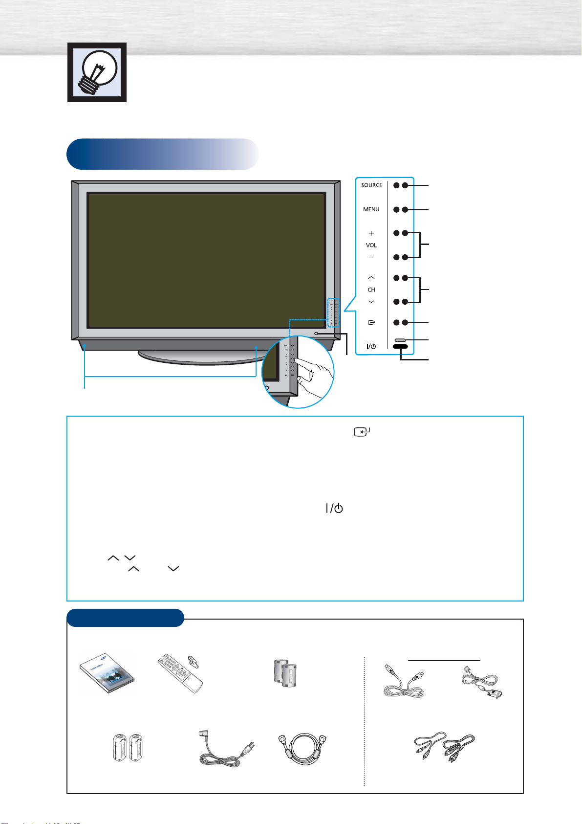
Front Panel
Your New Plasma Display Panel
8
Checking Accessories
Power Cord
(3903-000144)
Ferrite Core for Speaker cable
(3301-001502)
Antenna Cable
(BN39-00333A)
Component Cables (RCA)
(AA39-00033A)
Owner’s Instructions
Remote Control/
AAA Batteries
(BN59-00443A)
Ferrite Core for Side AV Cable,
Digital Audio Out(Coaxial), Sub Woofer
(3301-001201)
S-VIDEO Cable
(AA39-40001E)
DVI Cable
(BN39-00072A)
Sold Separately
ΠSOURCE button
Press to display all of the available video sources
(TV, AV1, AV2, S-VIDEO1, S-VIDEO2,
COMPONENT, DVI, and HDMI).
´ MENU button
Displays the main on-screen menu.
ˇ VOL(+,-) button
Press to increase or decrease the volume.
Also used to select or adjust items on the
on-screen menu.
¨ CH( , ) button
Press CH or CH to change channels.
Also used to move up or down in the on-screen
menu.
ˆ ENTER( ) button
Press to confirm a selection.
Ø Power Indicator
- Power Off : Red
- Power On : Off
- Timer On : Green
∏
Press to turn the PDP on and off.
” Remote Control Signal Receiver
Aim the remote control towards this spot on
the PDP.
’ Speakers
TOUCH buttons.
Press to operate the TV.
Œ
´
ˇ
¨
ˆ
Ø
∏
”
’
Once you have unpacked your PDP, check to make sure that you have all the parts shown here.
If any piece is missing or broken, call your dealer.
Page 9
9
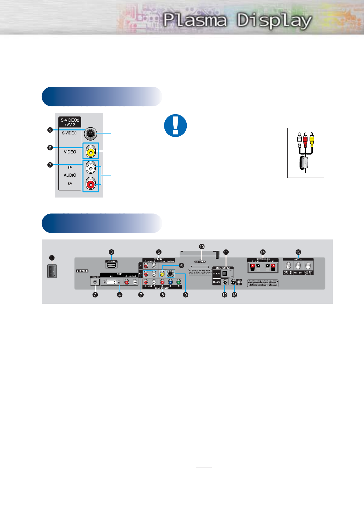
Rear Panel
Side of the TV
ŒPOWER IN
Connect the supplied power cord.
´SERVICE
Connector for service only.
ˇHDMI IN
Connect to the HDMI jack of a device with
HDMI output.
¨DVI IN (DVI / R-AUDIO-L)
Connect to the digital video and audio
output jack of a device with DVI output.
ˆAV IN/OUT (R-AUDIO-L)
Audio outputs for external device.
ØVIDEO
Video inputs for external devices, such as
a camcorder or VCR.
∏R-AUDIO-L
Audio inputs for external devices, such as
a camcorder or VCR.
”COMPONENT IN
Video (Y/PB/PR) and audio (L-AUDIO-R)
inputs for component.
’S-VIDEO
Video inputs for external devices with an
S-Video output, such as a camcorder or VCR.
˝cableCARD
Insert the cableCARD into the slot.
ÔOPTICAL DIGITAL AUDIO OUT
Connect to a Digital Audio component.
COAXIAL DIGITAL AUDIO OUT
Connect to a Digital Audio component.
ÒSUB-WOOFER OUT
Connect to an active SUB-WOOFER.
ÚEXT SPEAKER (8Ω)
Connectors for external rear speakers.
ÆANT (75Ω)
75Ω Coaxial connector for Antenna/Cable
Network.
Note
• The HDMI IN, DVI IN jack is not compatible
with PC.
Audio Input (L, R)
Video Input
S-Video Input
Ferrite Cores
The ferrite cores are used to
attenuate undesired signals. When
connecting cables, attach one of
these ferrite cores to the cable near
the connector.
When you connect Side AV cable,
Digital Audio out(Coaxial), sub
woofer cable, and Speaker cables,
first bind the ferrite core around
each cables to secure it.
Page 10
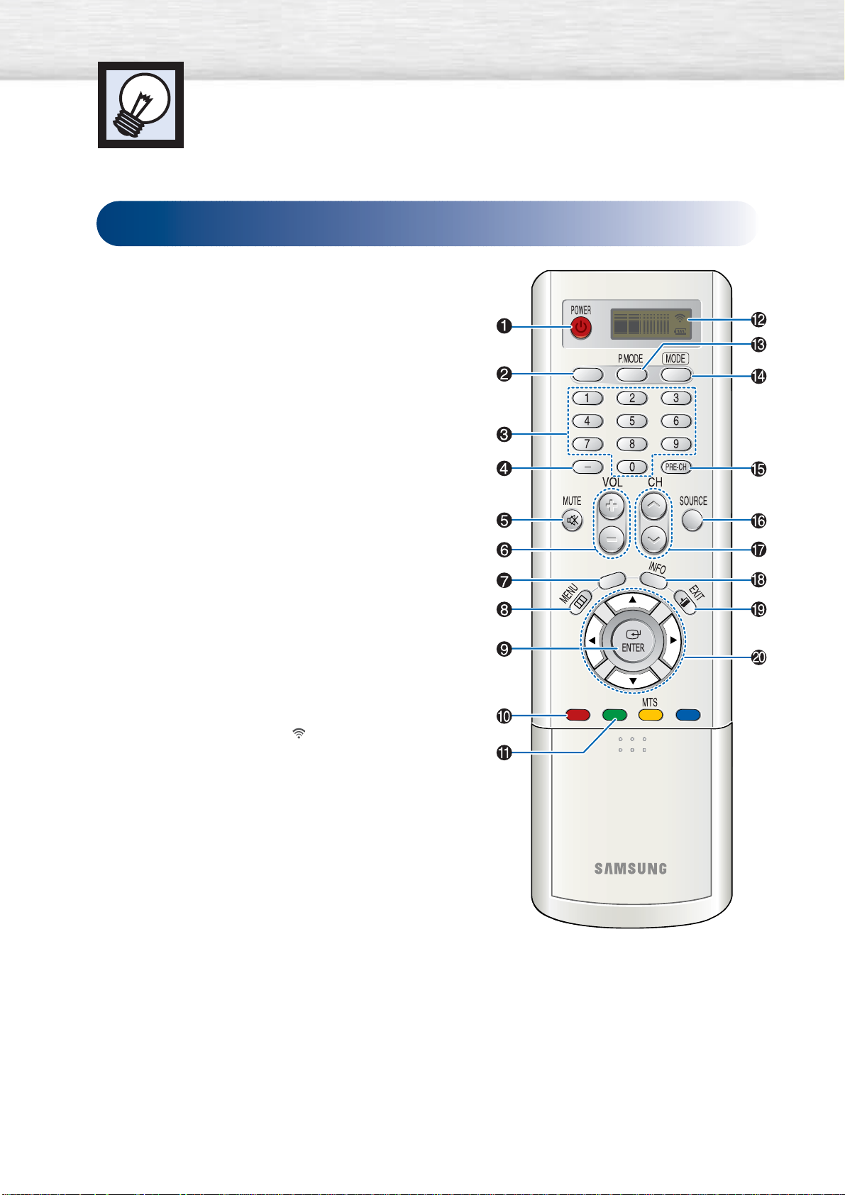
Remote Control Buttons
ŒPOWER button
Turns the PDP on and off.
´ANTENNA button
Press to select “AIR” or “CABLE”.
ˇNumber buttons
¨
-
button
Press to select additional channels (digital and analog)
being broadcast by the same station. For example, to
select channel “54-3”, press “54”, then press “-” and “3”.
ˆMUTE button
Press to mute the PDP sound.
ØVOL (Volume) buttons
Use it to adjust volume.
∏GUIDE button
Press to display he on-screen Electronic Program Guide
(EPG).
”MENU button
Displays the main on-screen menu.
’ENTER button
Confirms a selection.
˝FAV. CH button
Press to switch to your favorite channels.
ÔCH. LIST
Displays the channel list.
LCD Display
When you press a button, ‘ ‘ appears along with
selected mode (TV, VCR, CATV, DVD, or STB) and
the remote's battery charge status.
ÒP.MODE button
Adjust the PDP picture by selecting one of the preset
factory settings (or select your personal, customized
picture settings).
ÚMODE button
Selects a target device to be controlled by the Samsung
remote control (i.e., VCR, Cable box, DVD players, or
Samsung STB). If you change modes, the new mode is
momentarily displayed on LCD.
ÆPRE-CH button
Tunes to the previous channel.
ıSOURCE button
Press to display all of the available video sources
(TV, AV1,
AV2, S-VIDEO1, S-VIDEO2, COMPONENT, DVI, and HDMI).
˜CH (Channel) buttons
Use it to switch channels.
¯INFO button
Press to display information on the PDP screen.
˘EXIT button
Press to exit the menu.
¿Up/Down Left/Right buttons
Control the cursor in the menu.
10
Remote Control
ANTENNA
GUIDE
FAV. CH CH. LIST
PIP
Page 11
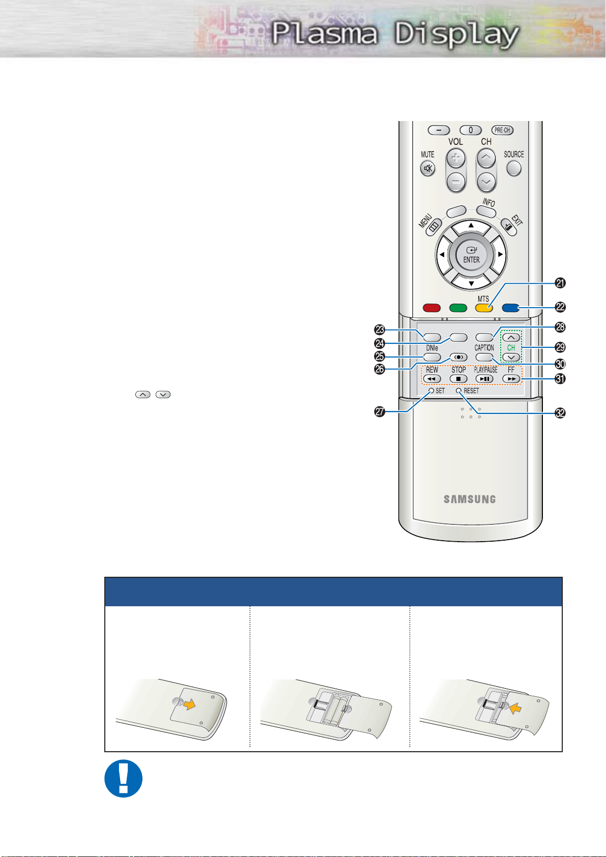
¸MTS button
Press to choose stereo, mono or Separate Audio
Program (SAP broadcast).
˛PIP button
Activates picture in picture.
◊ASPECT button
Press to change the screen size.
±STILL button
Press to pause the current screen.
≠DNIe button
Activates DNIe (Digital Natural Image engine).
–SRS button
Selects TruSurround XT mode.
—SET button
Used during set up of this Samsung remote control,
so that it will work compatibly with other devices
(VCR, Cable Box and DVD).
÷SLEEP button
Press to select a preset time interval for automatic
shut off.
®PIP control buttons
CH
,
: Displays the available channels in
sequence. (These buttons change
channels in the PIP window only.)
∑CAPTION button
Controls the caption decoder.
µVCR, DVD control buttons
Controls VCR tape or DVD disc functions: Stop,
Rewind, Play/Pause, and Fast Forward.
¥RESET button
If your remote control is not functioning properly, take
out the batteries and press the reset button for about
2~3 seconds. Re-insert the batteries and try using the
remote control again.
11
Installing the Batteries in Your Remote Control
1
Slide the back cover
to open the battery
compartment of the
remote control.
3
Slide the cover back into
place.
2
Install two AAA size batteries. Make sure to match the
“+” and “-” ends of the batteries with the diagram
inside the compartment.
Remote Control Operation Range.
You can use your remote control within a distance of 23 feet and an angle of 30 degrees
from the left and right sides of the PDP’s remote control receiver.
GUIDE
FAV. CH
CH. LIST
ASPECT
STILL
PIP
SLEEP
SRS
Page 12
Wall Installation Instructions
1
Do not install the PDP on any location other than a vertical wall.
2
To protect the performance of the PDP and prevent problems, avoid the following locations:
• Do not install next to smoke and fire detectors.
• Do not install in an area subjected to vibration or high voltage.
• Do not install near or around any heating apparatus.
3
Use only recommended parts and components.
12
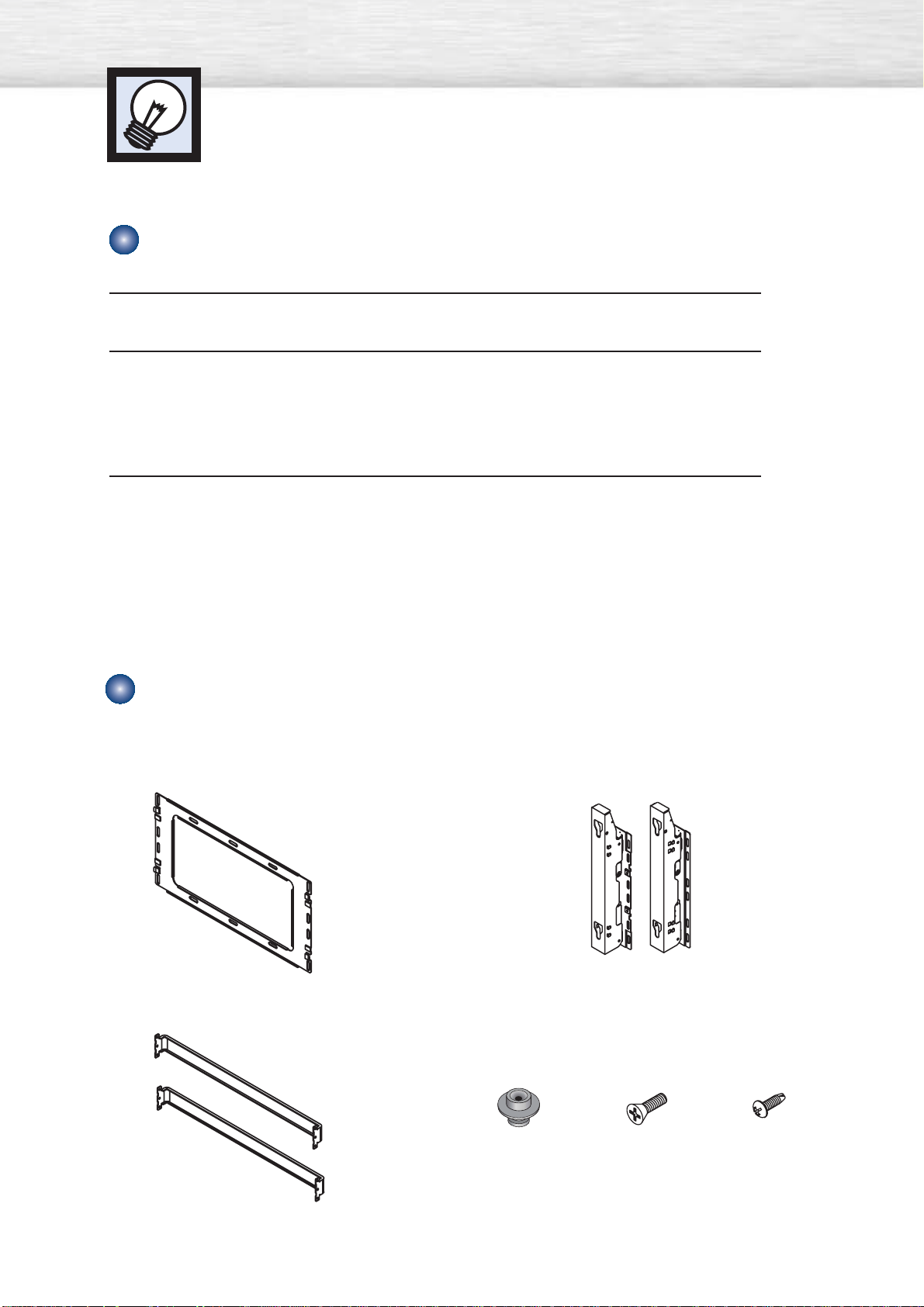
Installation Notes
Insulation Holder :
4EA
SCREW! : 4EA SCREW@ : 12EA
1EA
2EA
LEFT : 1EA RIGHT : 1EA
Parts (Wall attachment panel is sold separately. Check with your dealer.)
Wall Mount Bracket
ASSY-HINGE
Support Bars
Screws
Page 13
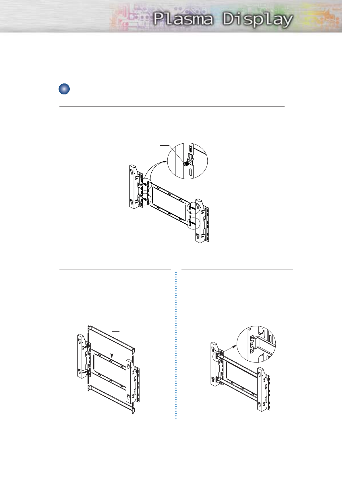
1
The wall mount comes packaged in 3 parts. These parts must be assembled together.
Please tighten the captive screws(4EA) in the direction of the arrow after assembling
the bracket. Install the Wall Mount Bracket after the screws are securely inserted
into the wall.
2
After installing the wall mount bracket,
assemble the support bars and hinges
(as illustrated) using screws provided.
(12 screws(@) are provided. For safety
reasons, make sure all 12 screws are
firmly attached.)
13
How to assemble the Wall Mount Bracket
ASSY-HINGE (LEFT)
Separate ASSY-HINGE
into left and right.
Wall Mount Bracket
Wall Mount Bracket
Support Bars
Support Bars
Captive Screws
ASSY-HINGE
(RIGHT)
ASSY-HINGE
(LEFT)
ASSY-HINGE
(RIGHT)
3
After securing the screws, be sure that
every part is firmly attached (as shown
in the illustration).
ASSY-
HINGE
(LEFT)
ASSY-HINGE
(RIGHT)
Page 14
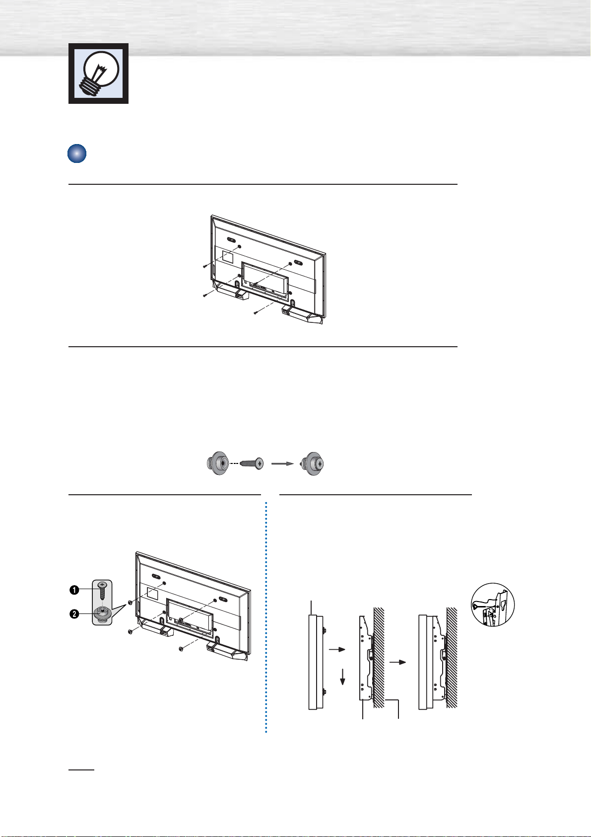
1
Remove the screws from the back of the PDP.
2
Connect insulation holders to screws (see the illustration below).
• If you are uncertain about installation, hire a specialist to install the wall mount bracket.
• Be sure to check that the insulation holders are completely secured on both the left
and right side after hanging the PDP on the wall mount bracket.
• Be careful to avoid getting your fingers caught during installation.
• Make sure the wall attachment panels are tightened. Otherwise the PDP may fall.
Note
•A 5 inch(12.7 cm) gap is needed between the back of the Plasma TV and the wall.
Wall Installation Instructions
14
Fixing the PDP panel to the wall attachment panel bracket
3
Tighten the screws of the insulation
holders to the back of the PDP.
4
Put the 4 insulation holders on the PDP
in the grooves of the wall mount
bracket and pull down on the PDP (Œ)
to secure it to the wall mount bracket
(´). Tighten the screws as shown (ˇ)
so that the PDP cannot be separated
from wall mount bracket.
PDP panel
Wall attachment panel
bracket
Wall
Œ
´
ˇ
Page 15

15
Notes
• Contact an authorized technician when installing the wall attachment panel.
• After hanging the PDP panel on the wall attachment panel, make sure that the Insulation
holders are completely hung.
• Be careful not to get your fingers caught during installation.
• Make sure the wall attachment panel brackets are tightened. Otherwise, the PDP panel may
fall down.
• Please secure the mounting bracket on the wall surface after setting its angle at 0°.
How to Adjust Mounting Angle
Note
Note : Please secure the mounting bracket on the wall surface after setting its angle at 0°.
Factory default How to Adjust Mounting Angle
Please tighten the captive screw in the direction
of the arrow after assembling the bracket.
Hold onto the middle of the PDP to adjust
the angle (not the sides of the PDP).
1
Secure the set to the wall mount bracket.
(Please refer to the following instructions.)
2
Set the angle by pulling the upper end of the set attached
to bracket in the direction of the arrow.
3
The angle can be adjusted from 0° to 15° by ±2°.
Change Angle
1
Be sure to remove the safety pins underneath the PDP.
(Caution : If the safety pins are not removed, the angle cannot
be adjusted.) Any attempt to do so may cause damage to the PDP.
2
Hold onto the bottom of the PDP and pull forward fully as
directed by the arrow(as illustrated) to adjust the angle.
(0°~20° by 2°). Insert the safety pins to the front guide
holes on both sides as illustrated in figure
´
.
3
Viewing the PDP after connecting the external devices.
Remove the safety pins to adjust the angle to 0°, then secure
the safety pins again. (Warning : For safety, be sure to secure
the PDP using the safety pins. If the safety pins are not used,
the PDP may fall, causing serious injury.)
Connecting External Devices to the PDP
Safety pin
Page 16
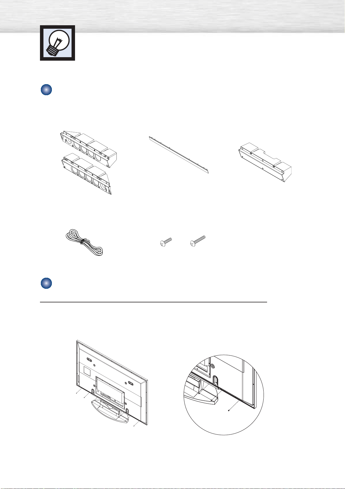
Installing the Speakers
This speaker installation guide is for the PSN5542(BN96-01328A) speakers.
16
Parts
How to Assemble the Speakers (When using the Stand)
2EA
1EA
1EA
Speakers
1EA
Middle Cabinet
(Wall Mount Only)
Speaker Dust Cover
Speaker Cable
Screw 2EA! Screw 6EA@
Screws
1
Remove the screws indicated on the rear of the PDP (6 screws on the left and right
sides).
Page 17
17
Screw②
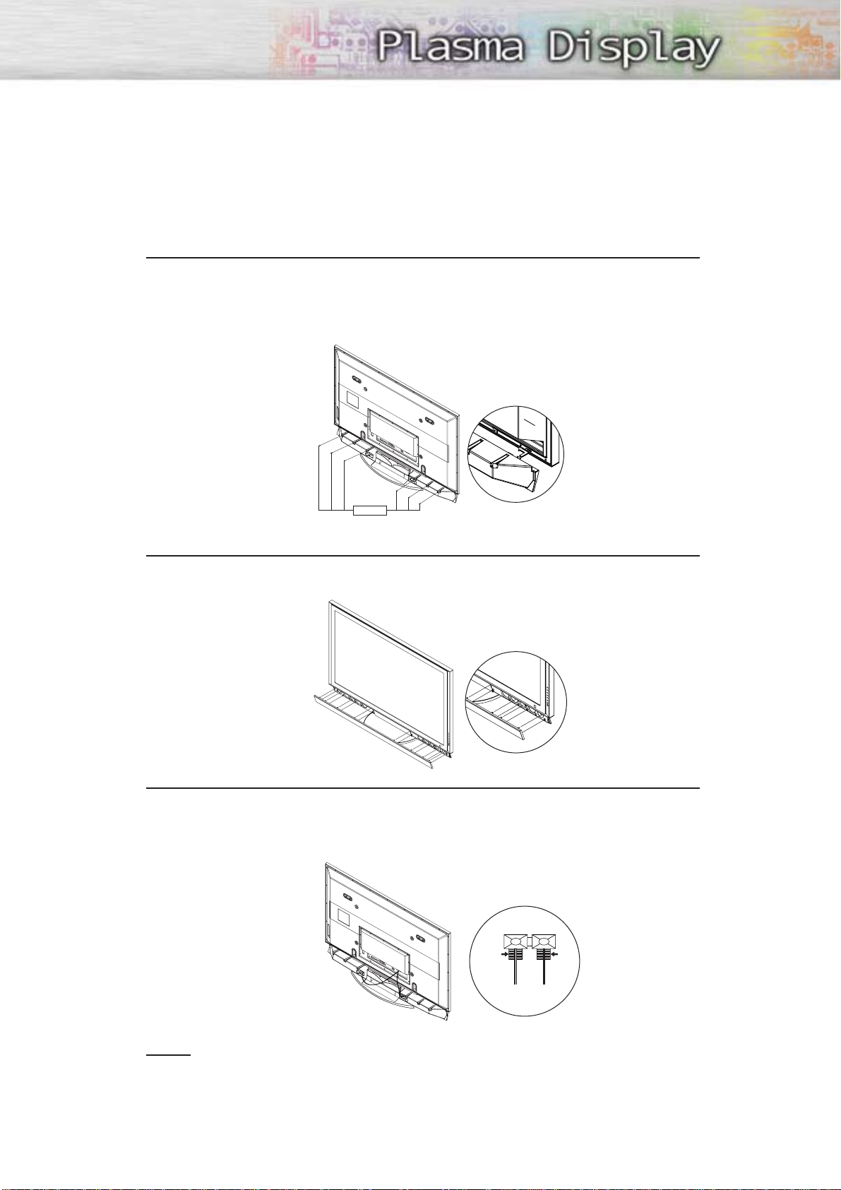
2
Set the speaker guide bracket into the square grooves located on either side of the
PDP’s bottom rear, then push the speaker guide bracket towards the center (as the
arrow illustrates). Secure the speaker guide bracket with provided screws @.
(Always use the proper screws, as indicated.)
3
Secure the speaker dust cover by setting it into the grooves located on the front side
of the speakers.
4
Connect the speakers to the PDP using the speaker cable.
The connection terminals are on the rear side of both the PDP and the speakers.
(Match the color coded terminals and cables.)
BLACK
BLACK RED
RED
Notes
• When moving the PDP with the speakers attached, be sure to hold onto the PDP
to prevent damage. (Damage may occur to the speaker connecting brackets or
the speakers.)
• Speakers of 8Ω impedance, 15W Nom. Power, 30W Max. Power is recommended.
Page 18
Installing the Speakers
18
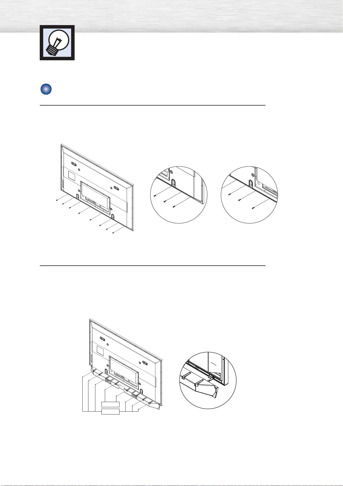
How to Assemble the Speakers (Wall Mount)
1
Remove the screws indicated on the rear of the PDP (6 screws on the left and right
sides, 2 screws on the center).
2
Set the speaker guide bracket into the square grooves located on either side of the
PDP’s bottom rear, then push the speaker guide bracket towards the center (as the
arrow illustrates). Secure the speaker guide bracket with provided screws @.
Secure the middle cabinet to the center of the PDP with a screw !.
(Always use the proper screws, as indicated.)
Screw②
Screw①
Page 19
19
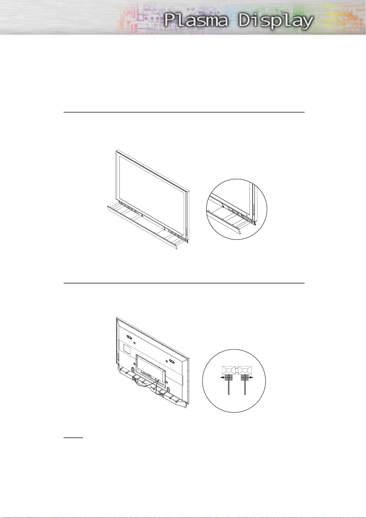
3
Secure the speaker dust cover by setting it into the grooves located on the front side
of the speakers.
4
Connect the speakers to the PDP using the speaker cables.
The connection terminals are on the rear side of both the PDP and the speakers.
(Match the color coded terminals and cables.)
Notes
• When moving the PDP with the speakers attached, be sure to hold on to the PDP
to prevent damage. (Damage may occur to the speaker connecting brackets or
the speakers.)
• Speakers are 8Ω impedance, 15W Nom. Power, 30W Max. Power is recommended.
BLACK
BLACK RED
RED
Page 20
➤
➤
Two or more people should carry the PDP. Never lay the PDP on the floor because of possible damage to the screen.
Always store the PDP upright.
20
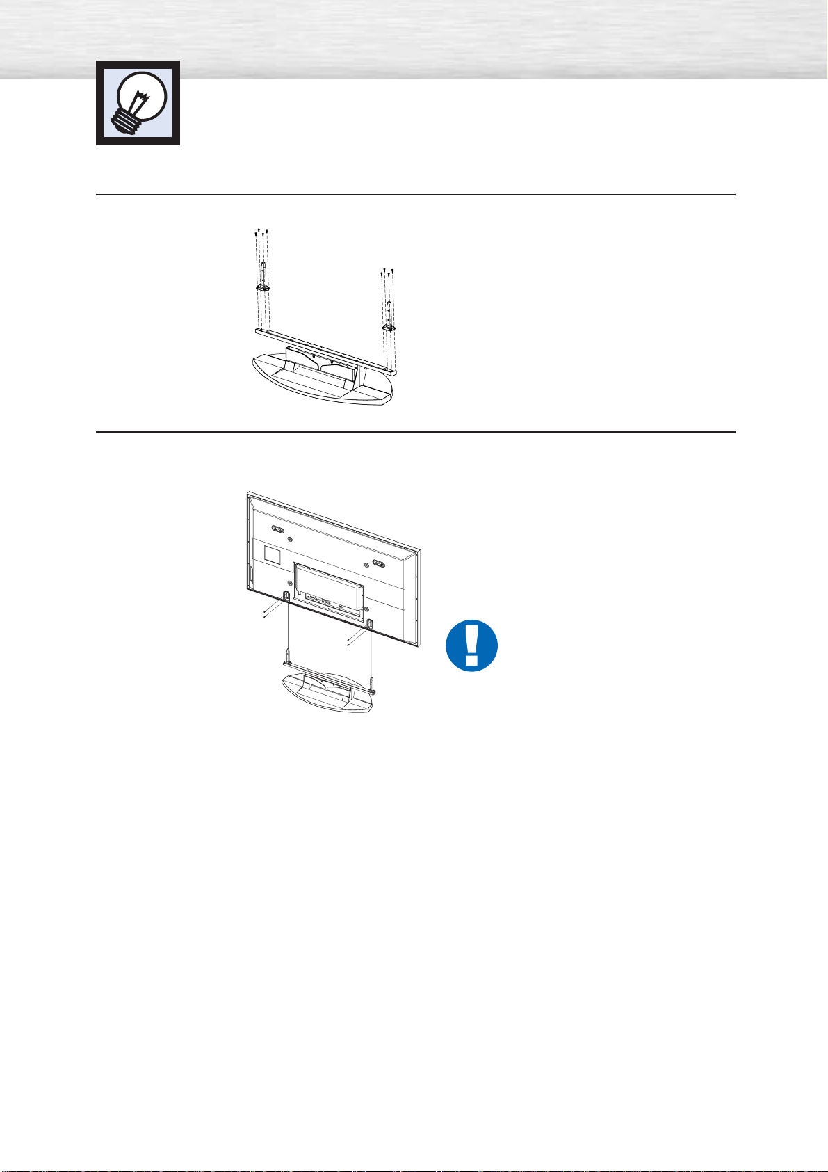
1
Firmly secure the pegs to the both sides of the stand base using 8 screws provided.
How to assemble the Stand-Base
2
Using the 4 screws for securing the stand pegs and the monitor, firmly attach the monitor to the stand
pegs. (The exterior of the set may be different than the picture.)
Warning
Firmly secure the stand for the PDP before
moving it, as the stand may fall and
could cause serious injury.
Page 21

PLASMA DISPLAY PANEL
Connections
Connecting VHF and UHF Antennas ..............................................22
Connecting Cable TV....................................................................23
Connecting CableCARD................................................................25
Connecting a VCR........................................................................26
Connecting a Camcorder ..............................................................27
Connecting a DVD Player..............................................................28
Connecting a DTV Receiver ..........................................................29
Connecting to HDMI (High Definition Multimedia Interface) ..............30
Connecting a Digital TV Set-Top Box ..............................................31
Connecting a Digital Audio System ................................................32
Connecting to an Analog Amplifier/Sub woofer Speaker ..................33
Page 22
Connecting VHF and UHF Antennas
22
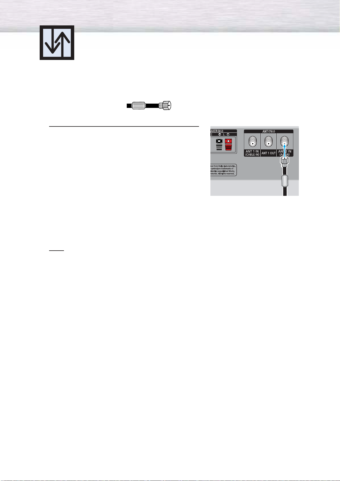
Antennas with 75-ohm Round Leads
If your antenna looks like this: it has 75-ohm round leads.
1
Plug the antenna lead into the ANT 2 IN(AIR IN)
on the PDP.
Use the antenna cable, an accessory included
in the product package.
Note
• When Antenna is set to AIR, ANT 1 IN(CABLE IN) signal will be the output from ANT1 OUT.
(See “Selecting the antenna.” on page 84.)
Page 23
23
Connecting Cable TV
You can connect different cable systems to your PDP, including cable without a Cable box,
and cable with a Cable box that descrambles some or all channels.
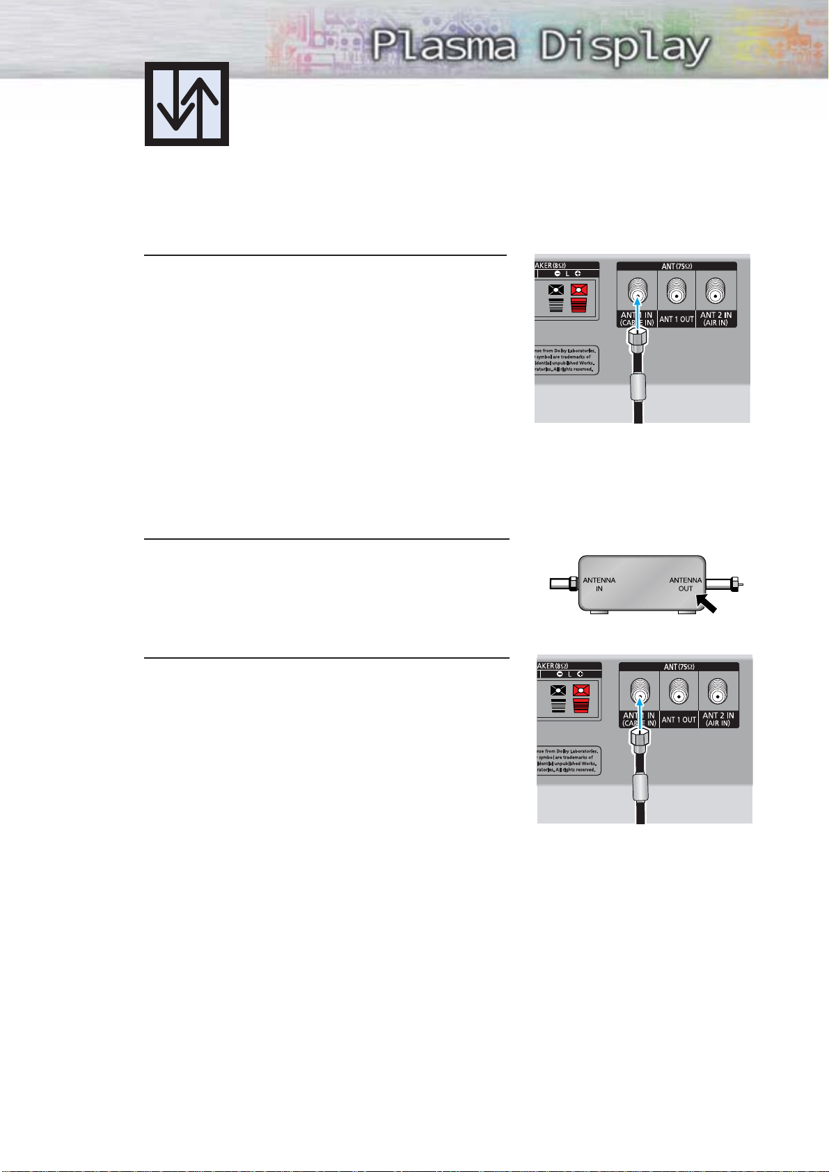
Cable without a Cable Box
1
Plug the incoming cable into the ANT 1 IN(CABLE IN)
on the PDP.
Use the antenna cable, an accessory included
in the product package.
Cable with a Cable Box that Descrambles All Channels
1
Find the cable connected to the ANTENNA OUT
terminal on your Cable box. This terminal might be
labeled "ANT OUT", "VHF OUT" or simply "OUT".
2
Connect the cable to the ANT 1 IN(CABLE IN) on the
PDP.
Use the antenna cable, an accessory included
in the product package.
Page 24
24
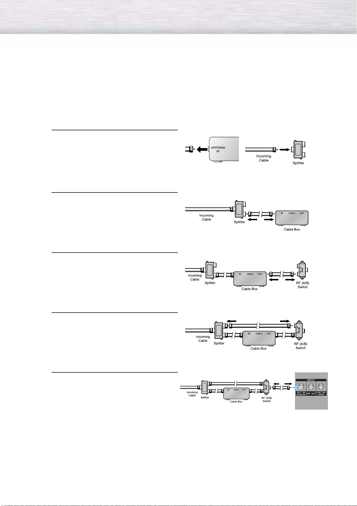
Cable with a Cable Box that Descrambles Some (But Not All) Channels
To complete this connection you will need a two-way splitter, an RF (A/B) switch, and four coaxial
cables (which you can buy from your Samsung dealer or any electronics store).
1
Find and disconnect the cable that is
connected to the ANTENNA IN terminal of
your Cable box.
This terminal might be labeled "ANT IN",
"VHF IN" or simply, "IN". Connect this
cable to a two-way splitter.
2
Connect a coaxial cable between an
OUT terminal of the splitter and the
IN terminal of the Cable box.
3
Connect a coaxial cable between the
ANTENNA OUT terminal of the Cable box
and the B-IN terminal of the A/B switch.
4
Connect a coaxial cable between the
ANTENNA OUT terminal of the Cable box
and the B-IN terminal of the A/B switch.
5
Connect the last coaxial cable between the
OUT terminal of the RF (A/B) switch and
the ANT 1 IN(CABLE IN) on the PDP.
After you've made this connection, set the A/B switch to the "A" position for normal viewing.
Set the A/B switch to the "B" position to view scrambled channels. (When you set the A/B switch
to "B", you will need to tune your Set-Top Box to the Cable box's output channel, which is usually
channel 3 or 4.)
Page 25
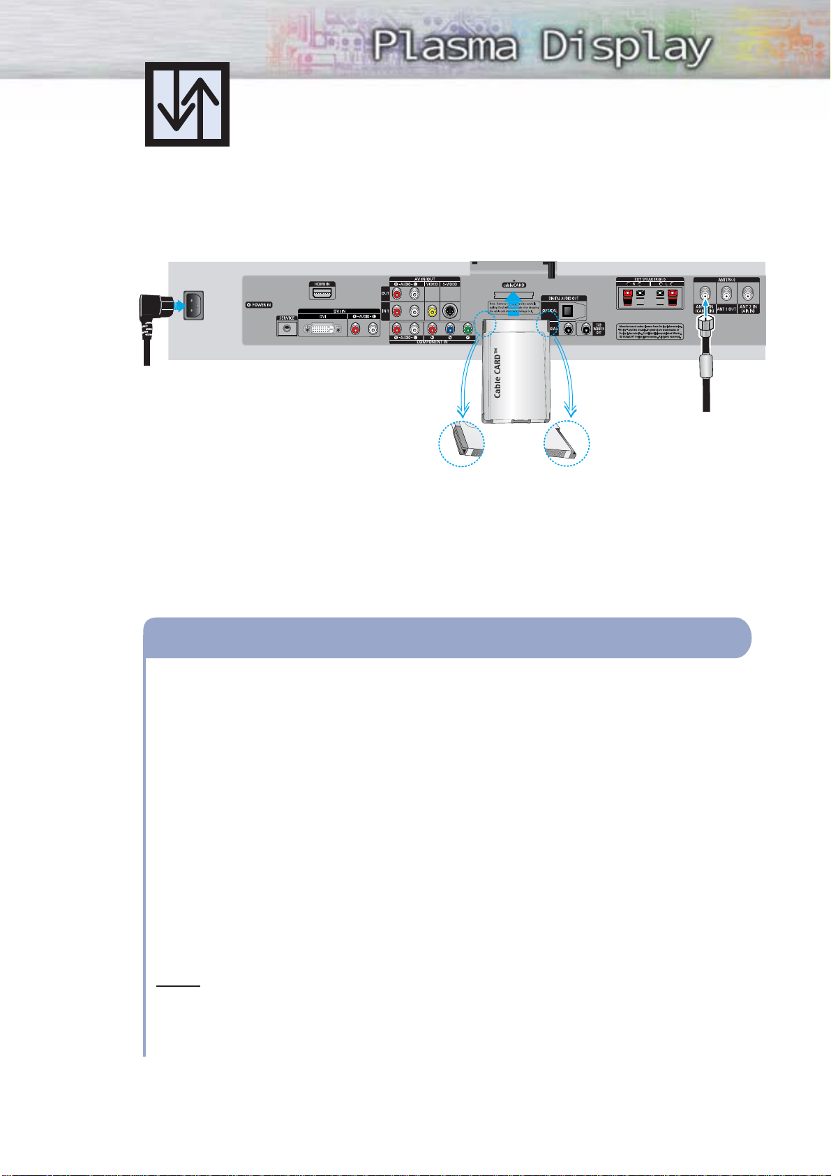
25
Connecting CableCARD
You must obtain a CableCARD from a local cable service provider.
PDP
Insert the CableCARD into the “CableCARD” slot and the message “CableCARD Inserted” is
displayed on the screen. If the channel information does not exist, the message “Updating
Channel List” is displayed during channel information configuration.
It could take several minutes to update the channel information depending on your cable
service provider.
The pairing information containing a telephone number, CableCARD ID, Host ID, and other
information will be displayed in about 2~3 minutes. If an error message is displayed, please
contact your service provider.
When the channel information configuration has finished, the message “Updating
Completed” is displayed, indicating that the channel list is now updated.
The Channel list can now be displayed by pressing CH.LIST button.
Notes
• Once the channel list has been updated, only the channels on the channel list can be
selected.
• Remove the cable card by carefully pulling it out with your hands since dropping the cable
card may cause damage to it.
How to Connect
1
2
3
4
Power cord
From cable TV
Please insert the card
as shown.
Page 26
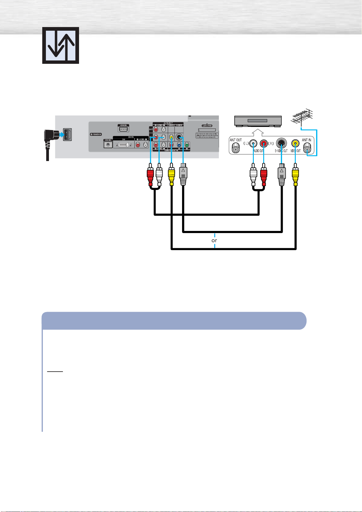
26
Connecting a VCR
Connecting a VCR to the Video or S-Video/Audio jack
Connect the Video/Audio cables between the VIDEO or S-VIDEO / L - AUDIO - R jacks on the
PDP and VIDEO or S-VIDEO / L - AUDIO - R output jacks on the VCR. (Note: For better video,
use an S-Video cable.)
Note
• Please be sure to match the color coded input terminals and cable jacks.
Videotape Playback:
1. Turn on your PDP.
2. Press the SOURCE button to select “Video(AV1 or AV2)” or “S-Video(S-VIDEO1 or S-VIDEO2)”.
3. Turn on your VCR, insert a videotape and press the Play button.
How to Connect
PDP
S-Video cable
Audio cable
Video cable
VCR
Power cord
Page 27
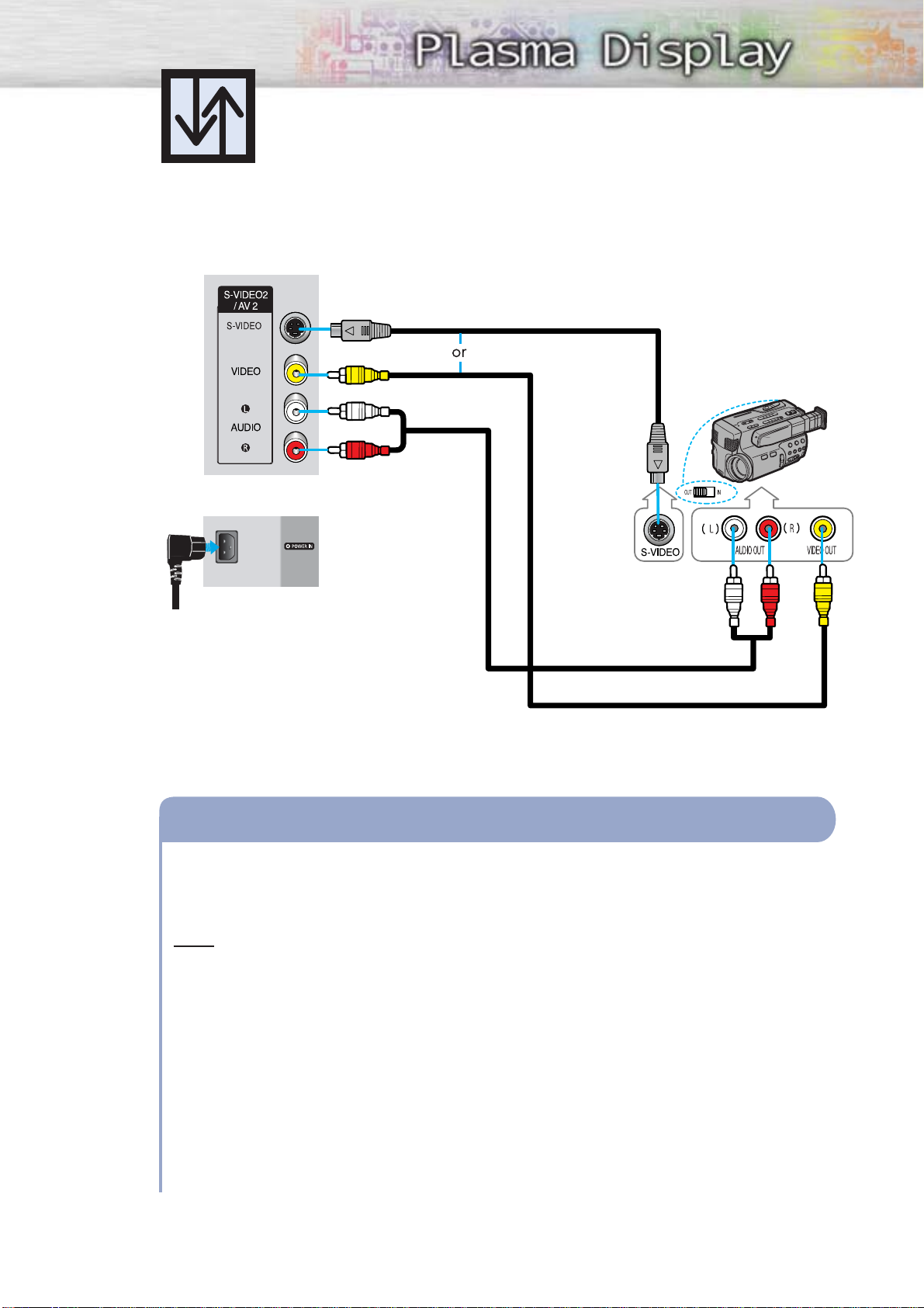
27
Connecting a Camcorder
Connect a Video/Audio cable between the VIDEO or S-VIDEO / L - AUDIO - R jacks on the
PDP and the VIDEO or S-VIDEO /AUDIO output jacks on the camcorder. (Note: For better
video, use an S-VIDEO cable.)
Note
• Please be sure to match the color coded input terminals and cable jacks.
Viewing Tapes
1. Turn on your PDP.
2. Press the SOURCE button to select “Video(AV1 or AV2)” or “S-VIDEO(S-VIDEO1 or
S-VIDEO2)”.
3. Turn on your camcorder and set it to video mode. (For details, refer to your camcorder
owner’s instructions.)
4. Set the IN/OUT switch on your camcorder to OUT.
5. Insert the tape into the camcorder and press the Play button.
How to Connect
Viewing camcorder tapes
Audio cable
Video cable
PDP(SIDE A V2)
PDP
REAR PANEL
S-Video cable
Camcorder
Power cord
Page 28
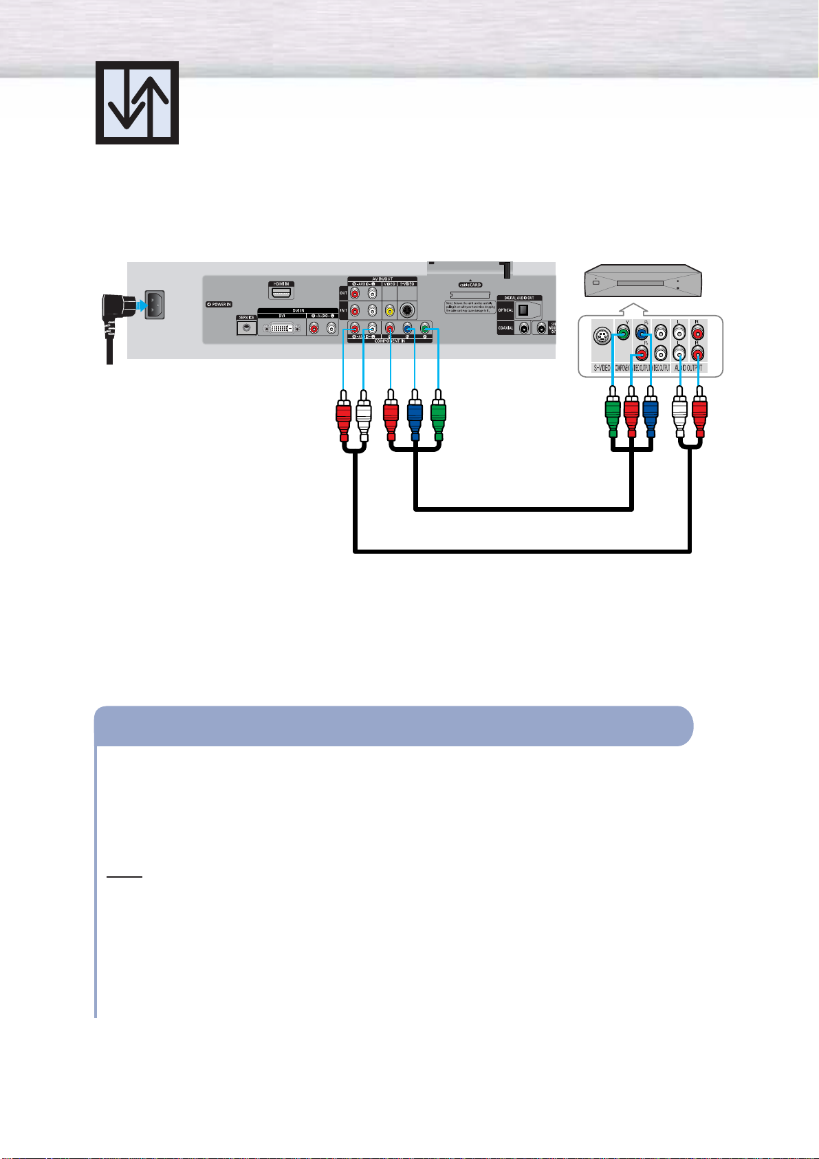
Connecting a DVD Player (480i, 480p)
This PDP displays the optimum picture in 720p mode.
28
Playing DVD
Audio cable
Component cable
Connect the Y, PB, PR (COMPONENT) input jacks on the PDP with Y, PB, PR output jacks on
the DVD player using a component cable.
Connect the AUDIO L/R(COMPONENT) input jacks on the PDP with the AUDIO output jacks
on the DVD player using a audio cable.
Note
• Please be sure to match the color coded input terminals and cable jacks.
To Play DVD:
1. Turn on your PDP.
2. Press the SOURCE button to select “COMPONENT”.
3. Turn on your DVD player, insert a DVD disc and press the Play button.
• For an explanation of component video, see your DVD owner’s instructions.
How to Connect
1
2
PDP DVD Player
Power cord
Page 29
29
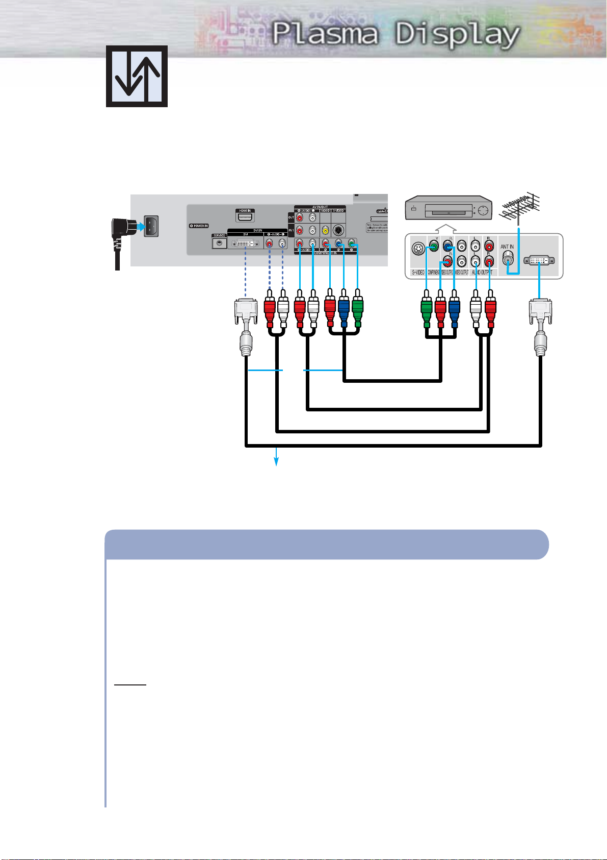
Connecting a DTV Receiver
(480p, 720p, 1080i)
This PDP displays the optimum picture in 720p mode.
Watching DTV
Component cable
Audio cable
DVI cable
Connect the cable or antenna to the antenna input jack on the DTV.
Connect the Y, PB, PR (COMPONENT) or DVI input jacks on the PDP to the Y, PB, PR or DVI
output jacks on the DTV receiver using a component or DVI-D cable.
Connect the AUDIO L/R(COMPONENT or DVI) input jacks on the PDP with the AUDIO
output jacks on the DTV receiver using an audio cable.
Notes
• Please be sure to match the color coded input terminals and cable jacks.
• The DVI IN jack is not compatible with PC.
To Watch DTV:
1. Turn on your PDP.
2. Press the SOURCE button to select “COMPONENT” or “DVI”.
3. Turn on your DTV receiver.
• For an explanation of component video, see your DTV receiver owner’s instructions.
How to Connect
1
2
3
Use a DVI-D video cable.
PDP
DTV Receiver
or
Power cord
Page 30
30
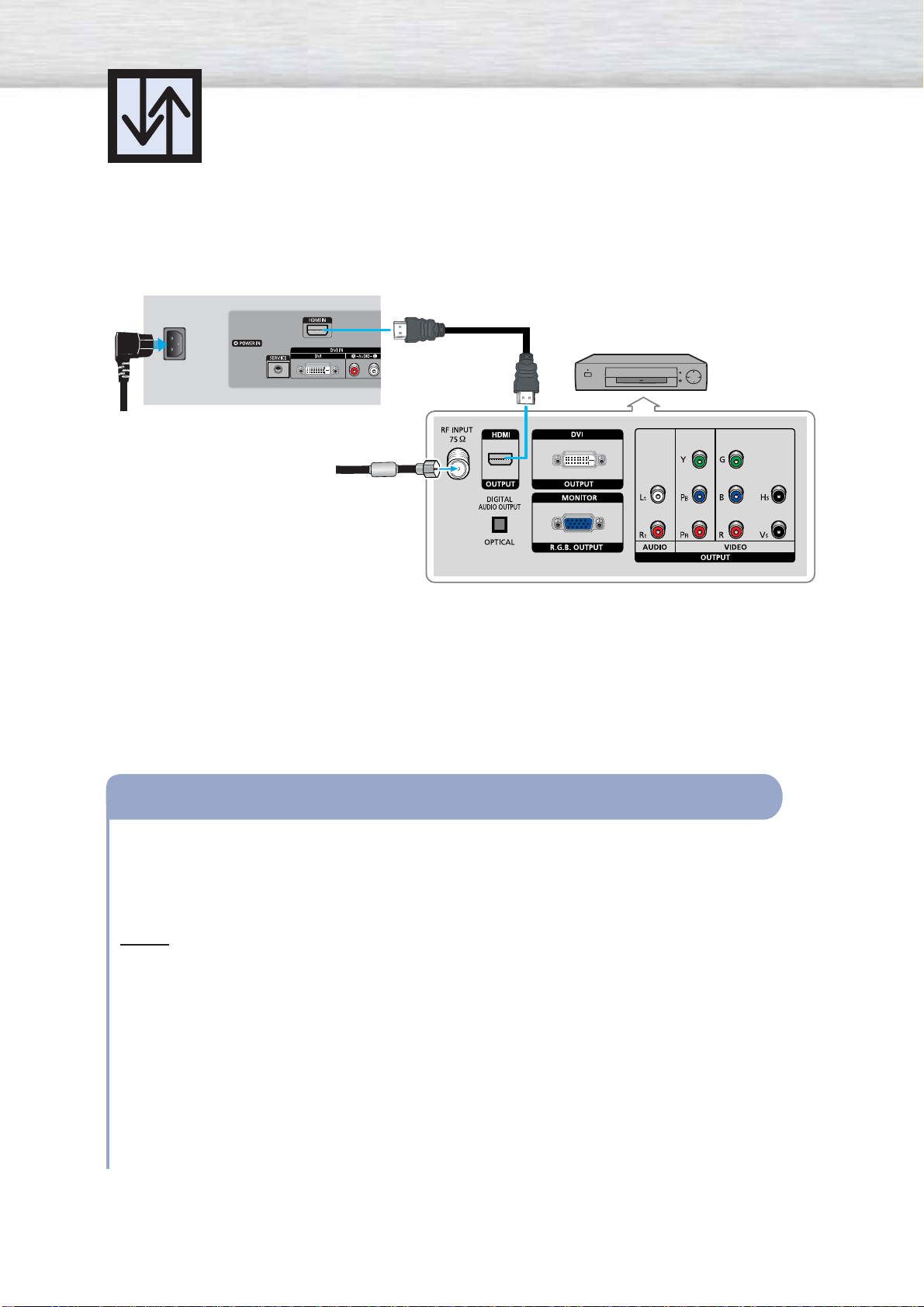
Watching DTV
Connecting to HDMI
(High Definition
Multimedia Interface) (480p, 720p, 1080i)
Connect the cable or antenna to the antenna input jack on the DTV.
Connect the HDMI IN jack on the TV with the HDMI OUT jack on the DTV Set-Top Box
using a HDMI cable.
Notes
• Please make sure the HDMI source's power is on before selecting HDMI from the
“Source List”.
• The HDMI IN jack is not compatible with PC.
• Sound is not available when HDMI is connected using a combination DVD/HDMI cable.
To Watch DTV:
1. Turn on your PDP.
2. Press the SOURCE button to select “HDMI”.
3. Turn on your DTV receiver.
• For an explanation of HDMI video, see your DTV receiver owner’s instructions.
How to Connect
1
2
PDP
HDMI cable
DTV Set-Top Box
Power cord
Page 31

Connecting to DVI (Digital Visual Interface)
31
PDP
Connecting a Digital TV Set-Top Box
(480p, 720p, 1080i)
By inputting a high-bandwidth digital content protection High-Definition picture source
to the DVI IN jack on the TV, High-Definition pictures can be displayed on the
screen in their digital form.
Connect the DVI AUDIO (L, R) jacks on the TV with the AUDIO OUT jacks on the Set-Top Box
using a audio cable.
Connect the DVI IN jack on the TV and the VIDEO OUT jack on the Set-Top Box using a
DVI-D video cable.
Notes
• The DVI IN jack is not compatible with PC.
• Use a DVI 25-pin cable (commercially available) in order to digitally connect the TV with
a DTV Set-Top Box.
How to Connect
1
2
DTV Set-Top Box
Audio cable
DVI cable
Use a DVI-D video cable.
From cable
or Antenna
Power cord
Page 32

Connecting a Digital Audio System
There are many types of digital audio systems on the market today.
A simplified illustration of an audio system is shown below. For more information, see your
audio system owner’s manual.
32
If your audio system has a coaxial digital audio input, connect to the “COAXIAL” output jack
on the PDP.
If your audio system has a optical digital audio input, connect to the “OPTICAL“ output jack
on the PDP.
Be certain to remove the black cover from the optical output before inserting the cable.
If your system has both coaxial and optical digital audio inputs, SAMSUNG recommends
you use the optical digital output on the PDP.
Do not connect both optical and coaxial cables. This may damage your audio system.
• OPTICAL: converts the electric signal into an optical light signal, and transmits it through
glass fibers.
• COAXIAL: The digital audio signal is received through a coaxial copper cable.
How to Connect
1
2
3
PDP
Digital Audio System
or
Coaxial cable
Optical cable
Power cord
Page 33

Analog Amplifier
PDP
Connecting to an Analog Amplifier/ Sub woofer Speaker
The “AUDIO OUT” terminals cannot be used for external speakers. You must hook them up
to an amplifier.
When an audio amplifier is connected to the “AUDIO OUT” terminals:
Decrease the gain (volume) of the audio amplifier, and adjust the volume level with the
volume control on the PDP.
How to Connect
1
33
Audio cable
Powered Subwoofer
(Option)
Power cord
Page 34

Page 35

PLASMA DISPLAY PANEL
Operation
Turning the PDP On and Off ..........................................................36
Viewing the Menus and Displays....................................................39
Memorizing the Channels..............................................................40
Adding and Erasing Channels ......................................................43
Setting Up Your Remote Control ....................................................46
Viewing an External Signal Source ................................................48
Page 36

Turning the PDP On and Off
36
Turning the PDP On and Off
Press the POWER button on the remote control.
The PDP will be turned on and you will be able to use its
features. You can also use the POWER ( ) button on the
front of the PDP.
Note
• If your PDP isn’t turned on when the POWER button is
pressed: Press the
MODE
button to check if the TV mode
has been chosen ( ).
Plug & Play Feature
When the PDP is initially powered On, basic customer settings proceed automatically and subsequently:
Setting the language, checking the antenna input, memorizing the channels, and setting the time.
Note
• The Plug & Play function operates after plugging in the PDP for the first time.
1
Press the POWER button on the remote control.
The message “Menu language, channels and time
will be set.” is displayed.
Press the ENTER button, then “Select the language of
OSD” menu is automatically displayed.
2
Press the ENTER button to enter the language.
Press the ▲ or ▼ button to select language, then the
ENTER button. “Select the antennas to memorize.”
menu is automatically displayed.
Menu language, Channels
and Time will be set.
i
Start
Select the language of the OSD.
Menu Language : English
Plug & Play
Enter Skip
English
Spanish
French
Move
Page 37

37
3
Press the ▲ or ▼ button to memorize the channels of
the selected connection.
Press the ENTER button to select “Start”.
Notes
• If the antenna is connected to ANT 1(CABLE IN),
select “CABLE” and if it is connected to
ANT 2(AIR IN), select “AIR”.
• If both ANT 1 and ANT 2 are connected, select
the “Air + Cable”.
•
If the CableCARD is inserted into the “CableCARD”
slot on the rear panel, “Cable” and “Air+Cable”
are not available.
When selecting Cable TV :
Press the ▲ or ▼ button to select “Cable”, then press the
ENTER button.
Press the ▲ or ▼ button to select “STD”, “HRC”, or
“IRC”, then press the ENTER button.
4
The TV will begin memorizing all of the available
channels. After all the available channels are stored,
the Auto program menu reappears.
Press the ENTER button when channel memorization
is complete.
“Set to daylight savings time.” menu is automatically
displayed.
5
Press the ENTER button. Press the ▲ or ▼ button to
select “Yes” or “No”, then the ENTER button.
“Select your time zone in which you live” menu is
automatically displayed.
Select the antennas to memorize.
Air
Cable
Air + Cable
Plug & Play
Enter SkipMove
Start
Start
Start
Select the cable system.
STD
HRC
IRC
Plug & Play
Enter SkipMove
Plug & Play
Enter Skip
Channel Memory in Process.
AIR Channel 67
Stop
Plug & Play
Enter Skip
Stop.
7 Channels were memorized.
Air : 9.
OK
Set to daylight savings time.
Daylight Savings Time : English
Plug & Play
Enter Skip
No
Ye s
Move
Page 38

38
6
Press the ▲ or ▼ button to highlight the time zone
for your local area (and to move the highlight to
the appropriate time zone on the map of the
United States).
Press the ENTER button.
If you have received a digital signal, the time will
be set automatically. If not, see page 92 to set the
clock.
7
The message “Completed. Time will be updated
automatically.” is displayed.
When you have finished, press the ENTER button.
Select your time zone in which you live.
Plug & Play
Enter SkipMove
Eastern
Central
Mountain
Pacific
Alaska
Hawaii
Completed. Time will
be updated automatically.
i
OK
If you want to reset this feature...
1
Press the MENU button. Press the ▲ or ▼ button to
select “Setup”, then press the ENTER button.
2
Press the ▲ or ▼ button to select “Plug & Play”.
Press the ENTER button.
3
For further details on setting up options, refer to the
previous page.
Note
•Plug and Play can only be accessed in the TV mode.
… More
Color Weakness : Off
√
Fan : On √
Plug & Play √
DVI Signal : 861B √
CableCARD
TM
√
SetupTV
Move Enter Return
Language : English √
Time √
V-Chip √
Caption √
Menu Transparency : Medium √
Function Help : Off √
† More
SetupTV
Move Enter Return
Menu language, Channels
and Time will be set.
i
Start
Page 39

39
Viewing the Menus and Displays
Your PDP has a simple, easy-to-use menu system that appears on the PDP screen.
This system makes it convenient and fast to use features on the PDP.
Your PDP also lets you display the status of many of your PDP’s features.
Viewing the Menus
1
With the power on, press the MENU button on the
remote control. The main menu appears on the
screen. The Input menu is selected.
2
Press the ▲ or ▼ button to move to items in the
menu. Press the œ/√/ENTER buttons to display,
change, or use the selected items.
Press the ENTER ( ) button to enter items in
the menu. On screen menus disappear from the
screen automatically after about two minutes
or you can press the MENU or EXIT button on
your remote control to exit the menu.
Displaying Status Information
Press the INFO button on the remote control.
The PDP will display the Picture mode, Sound mode,
MTS, and Current Time.
Source List √
Edit Name √
InputTV
Move Enter Return
Air 28
Mono
Picture Mode : Dynamic
Sound Mode : Custom
MTS : Stereo
No Time Information
Page 40

40
Selecting a broadcast source
Before your television can begin memorizing the available channels, you must specify the type of signal
source that is connected to the TV (i.e., an antenna or a cable system).
1
Press the MENU button. Press the ▲ or ▼ button to
select “Channel”, then press the ENTER button.
2
Press the ▲ or ▼ button to select “Auto Program”,
then press the ENTER button.
Memorizing the Channels
Your TV can memorize and store all of the available channels for both “off-air”
(antenna) and cable channels. After the available channels are memorized, use the
CH and CH buttons to scan through the channels. This eliminates the need to
change channels by entering the channel digits. There are three steps for memorizing
channels: selecting a broadcast source, memorizing the channels (automatic) and
adding and deleting channels (manual).
Antenna : Air √
Auto Program √
Add / Delete √
Favorite Channels √
Name √
Fine Tune √
† More
ChannelTV
Move Enter Return
Antenna : Air √
Auto Program √
Add / Delete √
Favorite Channels √
Name √
Fine Tune √
† More
ChannelTV
Move Enter Return
Page 41

41
3
Press the ▲ or ▼ button to select the antenna
connection, then press the ENTER button.
Notes
• Air : “Air” antenna signal.
• Cable : “Cable” antenna signal.
• Air+Cable : “Air” and “Cable” antenna signals.
If the CableCARD is inserted into the “CableCARD”
slot on the rear panel, “Cable” and “Air+Cable”
are not available.
When selecting Cable TV system :
Press the ▲ or ▼ button to select “Cable”, then press the
ENTER button.
Press the ▲ or ▼ button to select “STD”, “HRC”, or
“IRC”, then press the ENTER button.
Note
• STD, HRC, and IRC identify various types of cable
TV systems. Contact your local cable company to
identify the type of cable system that exists in your
particular area. At this point the signal source has
been selected. Proceed to “Storing Channels in
Memory”.
Select the antennas to memorize
Air
Cable
Air + Cable
Auto ProgramTV
Move Enter Return
Start
Start
Start
Select the antennas to memorize
Air
Cable
Air + Cable
Auto ProgramTV
Move Enter Return
Start
Start
Start
Select the cable system.
STD
HRC
IRC
Auto ProgramTV
Move Enter Return
Page 42

42
Storing Channels in Memory
4
Press the ▲ or ▼ button to select the antennas to
memorize. Press the ENTER button to select “Start”.
5
Press the ENTER button to start the auto program.
The TV begins memorizing all available stations.
Press the ENTER button at any time to interrupt
the memorization process.
Press the EXIT button to exit.
Note
•
The TV must be connected to an antenna in
order to receive digital TV signals.
Even if a particular channel is deleted from the
memory, you can always tune to that channel
directly by using the number buttons on the
remote control.
Notes
• All available DTV and analog channels are automatically stored in memory when channels are
selected by directly accessing channels.
• It takes approximately 3 to 10 minutes to memorize channels.
Select the antennas to memorize
Air
Cable
Air + Cable
Auto ProgramTV
Move Enter Return
Start
Start
Start
Auto Program
Channel Memory in Process
AIR Channel 67
Stop
Enter Return
Page 43

43
1
Press the MENU button.
Press the ▲ or ▼ button to select “Channel”, then
press the ENTER button.
2
Press the ▲ or ▼ button to select “Add/Delete”,
then press the ENTER button.
3
Repeatedly pressing the ENTER button will alternate
between add channel and delete channel.
Press the CH or CH button to switch to the
appropriate channel, then repeat above.
Press the EXIT button to exit.
Adding and Erasing Channels
To add channels that were not memorized (or to delete unwanted channels from
memory).
Antenna : Air √
Auto Program √
Add / Delete √
Favorite Channels √
Name √
Fine Tune √
† More
ChannelTV
Move Enter Return
Antenna : Air √
Auto Program √
Add / Delete √
Favorite Channels √
Name √
Fine Tune √
† More
ChannelTV
Move Enter Return
Add / Delete
Air 16 Not In Memory
Press ENTER to add the channel.
Add
CH Move
Enter Return
Add / Delete
Air 16 In Memory
Press ENTER to delete the channel.
Delete
CH Move
Enter Return
Page 44

44
Changing Channels
Using the Channel Buttons
Press the CH or CH button to change channels.
When you press the CH or CH button, the PDP changes channels
in sequence. You will see all the channels that the PDP has memorized.
(The PDP must have memorized at least three channels.)
You will not see channels that were either erased or not memorized.
Directly Accessing Channels
Press the number buttons to go directly to a channel. For example, to select
channel 27, press “2” then “7”.
When you use the number buttons, you can directly select channels that were
either erased or not memorized. To change to single-digit channels (0~9) faster,
press “0” before the single digit. (For channel “4” press “0”, then “4”.)
Notes
• For quick channel change, press the number buttons and then press
‘ENTER’.
• After the process of updating the channel information using cable
card has been completed, only the number of channels on the
channel list can be directly accessed.
Using the PRE-CH button to select the previous channel
Press the PRE-CH button. The TV will switch to the last channel viewed.
To quickly switch between two channels that are far apart, tune to one
channel, then use the number button to select the second channel. Then,
use the PRE-CH button to quickly alternate between them.
Adjusting the Volume
Using the Volume Buttons
Press the VOL or VOL button to increase or decrease the volume.
Using Mute
Using the MUTE Button
At any time, you can temporarily cut off the sound using the MUTE button.
1
Press the MUTE button and the sound cuts off.
The word “Mute” will appear in the lower-left
corner of the screen.
2
To turn mute off, press the MUTE button again,
or simply press the VOL or VOL button.
MUTE
Page 45

45
Using the “-” Button
The “-” button is used to select stations that broadcast both a digital and analog signal.
For example, for Channel 7-1 (digital), press “7”, then “-”, then “1”.
For channel 7-2 (analog), press “7”, then “-”, then “2”.
Notes
• HD indicates the TV is receiving a Digital High Definition signal.
SD indicates the TV is receiving a Standard Definition signal.
• For quick channel change, press the number buttons and then press ‘ENTER’.
DTV CABLE
7 - 1
KYW-HD
HD
Picture Mode : Dynamic
Sound Mode : Custom
MTS : English
No Time Information
DTV CABLE
7 - 2
R
SD
Multi
Picture Mode : Dynamic
Sound Mode : Custom
MTS : English
No Time Information
Page 46

46
Setting Up Your Remote Control
This PDP's remote control can operate almost any VCR, Cable box or DVD. After it has been set up
properly, your remote control can operate in five different modes : TV, VCR, CATV, DVD, or STB.
Pressing the corresponding button on the remote control allows you to switch between these modes,
and control whichever piece of equipment you choose.
Notes :●The remote control may not be compatible with all DVD Players, VCRs, or Cable boxes.
●
The remote control can only operate Set-Top Boxes made by Samsung.
Setting Up the Remote to Operate Your VCR, Cable box or DVD player
1
Turn off your VCR (or Cable box, DVD player).
2
Press the MODE button. The Mode is changed
whenever MODE button is pressed.
3
Press the SET button on your TV's remote control.
4
Using the number buttons on your remote control,
enter three digits of the VCR (or Cable box, DVD
player) code listed on page 47 of this manual for
your brand of VCR (or Cable box, DVD). Make
sure you enter three digits of the code, even if
the first digit is a “0”.
(If more than one code is listed, try the first one.)
5
Press the POWER button on the remote control.
Your VCR (or Cable box, DVD) should turn on if your
remote is set up correctly. If your VCR (or Cable box,
DVD) does not turn on after setup, repeat steps
2, 3, and 4, but try one of the other codes listed for
your brand of VCR (or Cable box, DVD).
If no other codes are listed, try each code, 000
through 089 (or Cable box: 000 through 077,
DVD player: 000 through 008).
Notes
•When your remote control is in “VCR”, “CATV”, or “DVD” mode, the VCR control buttons (STOP,
REW, PLAY/PAUSE, and FF) still operate your VCR.
•You do not need to program the remote for Samsung STBs as the codes are pre-programmed.
Page 47

47
Remote Control Codes
VCR Codes
Cable Box Codes
DVD Codes
Page 48

48
Setting the Signal Source
1
Press the MENU button. Press the ENTER button to
select “Input”.
2
Press the ENTER button to select “Source List”.
3
Press the ▲ or ▼ button to select signal source, then
press the ENTER button.
4
Press the MENU button to exit.
Notes
• When you connect equipment to the PDP, you can choose between the following sets of jacks:
AV1, AV2, S-Video1, S-Video2, Component, DVI, or HDMI on the PDP’s rear panel.
• HDMI input can only be selected when the external device is turned on and connected via HDMI.
Viewing an External Signal Source
Use the remote control to switch between viewing signals from connected equipment,
such as VCR, DVD, Set-Top Box and the TV source (broadcast or cable).
➤
➤
Quick way to access viewing an external signal source :
Just press the “SOURCE” button on the remote control.
Source List √
Edit Name √
InputTV
Move Enter Return
TV
AV1 : - - - AV2 : - - - S-Video1 : - - - S-Video2 : - - - Component : - - - -
† More
Source ListTV
Move Enter Return
TV
AV1 : - - - -
AV2 : - - - S-Video1 : - - - S-Video2 : - - - Component : - - - -
† More
Source ListTV
Move Enter Return
Page 49

Assigning Names to External input mode
1
Press the MENU button. Press the ENTER button to
select “Input”.
2
Press the ▲ or ▼ button to select “Edit Name”, then
press the ENTER button.
3
Press the ENTER button.
Press the ▲ or ▼ button to select external device,
then press the ENTER button.
• You can select the VCR, DVD, D-VHS, Cable STB,
HD STB, Satellite STB, PVR STB, AV Receiver,
DVD Receiver, GAME, Camcorder, Combo, PC,
VOD STB, or TV.
• Set other signal sources (AV2, S-Video1, S-Video2,
Component, DVI, or HDMI) using the same
method as listed above.
4
Press the MENU button to exit.
49
Source List √
Edit Name √
InputTV
Move Enter Return
AV1 : - - - - √
AV2 : - - - - √
S-Video1 : - - - - √
S-Video2 : - - - - √
Component : - - - - √
† More
Edit NameTV
Move Enter Return
AV1 : TV
AV2 : - - - -
S-Video1 : - - - -
S-Video2 : - - - -
Component : - - - -
† More
Edit NameTV
Move Enter Return
†
- - - -
VCR
DVD
D-VHS
Cable STB
HD STB
Satellite STB
PVR STB
Page 50

Page 51

PLASMA DISPLAY PANEL
Picture Control
Customizing the Picture ................................................................52
Using Automatic Picture Settings ....................................................53
Selecting the Color Tone................................................................54
DNIe (Digital Natural Image engine) ..............................................55
Changing the Screen Size ............................................................56
Freezing the Picture ......................................................................58
Viewing the Picture-in-Picture..........................................................59
Setting the My Color Control Mode ................................................65
Selecting the DVI Standard ............................................................69
Page 52

Customizing the Picture
You can use the on-screen menus to change the Contrast, Brightness, Sharpness, Color,
and Tint settings of your PDP.
52
1
Press the MENU button. Press the ▲ or ▼ button to
select “Picture”, then press the ENTER button.
2
Press the ▲ or ▼ button to select “Custom”, then
press the ENTER button.
You will also see the items “Contrast”, “Brightness”,
“Sharpness”, “Color”, and “Tint”.
3
Press the ▲ or ▼ button to select the item you wish
to change, then press the ENTER button.
Press the œ or √ button to change the value of the
item.
4
Press the MENU button to exit.
Notes
• In the Component(480p, 720p, 1080i), DVI, HDMI mode, you can’t adjust the Tint.
• If you make any changes to these settings, the picture mode is automatically switched to custom.
• Each adjusted setting will be stored separately according to its input mode.
• When you make changes to Contrast, Brightness, Color, Tint, OSD color will also be adjusted
accordingly.
Contrast 100
Mode : Dynamic √
Custom √
Color Tone : Normal √
Size √
DNIe : On √
My Color Control √
† More
PictureTV
Move Enter Return
CustomTV
Move Enter Return
Contrast 100
Brightness 45
Sharpness 75
Color 55
Tint G 50 R 50
Page 53

53
1
Press the MENU button. Press the ▲ or ▼ button to
select “Picture”, then press the ENTER button.
2
Press the ENTER button to select “Mode”.
3
Press the ▲ or ▼ button to select “Dynamic”,
“Standard”, “Movie”, “Custom” picture setting,
then press the ENTER button.
4
Press the MENU button to exit.
• Choose Dynamic for viewing the TV during the day or when there is bright light in the room.
• Choose Standard for the standard factory settings.
•Choose Movie when viewing the movie.
• Choose Custom if you want to adjust the settings according to personal preference
(see “Customizing the Picture”, page 52).
Note
• Each adjusted value of Picture mode will be stored separately according to its input mode.
Using Automatic Picture Settings
Your PDP has automatic picture settings that allow you to adjust the video display easily.
➤
➤
Quick way to access the picture setting: Just press the “P.MODE”
button on the remote control.
Mode : Dynamic √
Custom √
Color Tone : Normal √
Size √
DNIe : On √
My Color Control √
† More
PictureTV
Move Enter Return
Mode : Dynamic
Custom
Color Tone : Normal
Size
DNIe : On
My Color Control
† More
PictureTV
Move Enter Return
Mode : Dynamic
Custom
Color Tone : Normal
Size
DNIe : On
My Color Control
† More
PictureTV
Move Enter Return
Dynamic
Standard
Movie
Custom
Dynamic
Standard
Movie
Custom
Page 54

54
Selecting the Color Tone
1
Press the MENU button. Press the ▲ or ▼ button to
select “Picture”, then press the ENTER button.
2
Press the ▲ or ▼ button to select “Color Tone”, then
press the ENTER button.
3
Press the ▲ or ▼ button to select “Cool2”, “Cool1”,
“Normal”, “Warm1”, or “Warm2”, then press the
ENTER button.
4
Press the MENU button to exit.
Mode : Dynamic √
Custom √
Color Tone : Normal √
Size √
DNIe : On √
My Color Control √
† More
PictureTV
Move Enter Return
Mode : Dynamic
Custom
Color Tone : Normal
Size
DNIe : On
My Color Control
† More
PictureTV
Move Enter Return
Cool2
Cool1
Normal
Warm1
Warm2
Mode : Dynamic
Custom
Color Tone : Normal
Size
DNIe : On
My Color Control
† More
PictureTV
Move Enter Return
Cool2
Cool1
Normal
Warm1
Warm2
Page 55

DNIe (Digital Natural Image engine)
Samsung’s new technology brings you more detailed images with contrast,
white enhancement and 3D noise reduction.
1
Press the MENU button. Press the ▲ or ▼ button to
select “Picture”, then press the ENTER button.
2
Press the ▲ or ▼ button to select “DNIe”, then press
the ENTER button.
3
Press the ▲ or ▼ button to select “Off”, “Demo”, or
“On”, then press the ENTER button.
•Off : Switches off the DNIe mode.
•Demo : The screen before applying DNIe appears
on the right and the screen after applying
DNIe appears on the left.
•On : Switches on the DNIe mode.
4
Press the MENU button to exit.
55
➤
➤
Quick way to select DNIe: Simply press the “DNIe” button under
the cover of the remote control.
Mode : Dynamic √
Custom √
Color Tone : Normal √
Size √
DNIe : On √
My Color Control √
† More
PictureTV
Move Enter Return
Mode : Dynamic
Custom
Color Tone : Normal
Size
DNIe : On
My Color Control
† More
PictureTV
Move Enter Return
Off
Demo
On
Mode : Dynamic
Custom
Color Tone : Normal
Size
DNIe : On
My Color Control
† More
PictureTV
Move Enter Return
Off
Demo
On
Page 56

56
Changing the Screen Size
Screen size selection depends on the type of video input.
1
Press the MENU button. Press the ▲ or ▼ button to
select “Picture”, then press the ENTER button.
2
Press the ▲ or ▼ button to select “Size”, then press
the ENTER button.
3
Press the œ or √ button to select the screen format
you want.
4
Press the MENU button to exit.
• 16:9 : Sets the picture to 16:9 wide mode.
• Panorama : Use this mode for the wide aspect ratio of a panoramic picture.
• Zoom1 : Magnifies the size of the picture on the screen.
• Zoom2 : Expands the Zoom1 format picture.
• 4:3 : Sets the picture to 4:3 normal mode.
➤
➤
Quick way to change the Screen size: Simply press the ASPECT button
under the cover of the remote control.
Mode : Dynamic √
Custom √
Color Tone : Normal √
Size √
DNIe : On √
My Color Control √
† More
PictureTV
Move Enter Return
Mode : Dynamic √
Custom √
Color Tone : Normal √
Size √
DNIe : On √
My Color Control √
† More
PictureTV
Move Enter Return
SizeTV
Move Enter Return
16:9
Panorama Zoom1 Zoom2
4:3
Page 57

57
16:9
Sets the picture to 16:9 wide mode.
Panorama
Converts regular 4:3 aspect ratio screen to
wide screen.
Zoom1
The screen size when Wide screen is vertically
enlarged.
Zoom2
The screen size when the Zoom1 screen is
vertically enlarged.
4:3
Sets the picture to 4:3 normal mode.
Notes
• In TV, VIDEO, S-VIDEO, and all COMPONENT modes, all screen modes can be selected.
(16:9 ➞Panorama ➞Zoom1 ➞Zoom2 ➞4:3).
• In TV(DTV), DVI, HDMI modes, only 16:9 & 4:3 modes can be selected.
•In Zoom1, Zoom2 modes, you can move the picture on screen by pressing the ▲ or ▼ button.
(All screen modes)
• Picture size will not change when PIP size is Double.
When you press the ASPECT button under the cover of the remote control, the PDP’s screen mode
should appear in sequence. The screen displays in this order: 16:9, Panorama, Zoom1, Zoom2, 4:3.
Note
• If you watch a still image or the 4:3 mode for a long time (over 2 hours), an image may be burned
onto the screen. View the TV in 16:9 or Panorama mode as much as possible.
16:9
Panorama 4:3
Zoom2 Move
Zoom1 Move
Page 58

58
Still
Press the STILL button on the remote control to freeze a
moving picture. Press again to cancel.
Notes
• The still picture will automatically be released after 3 minutes to prevent screen burn.
• If you press a remocon button in Still mode, the still picture will be cleared.
Freezing the Picture
Page 59

Selecting the PIP Screen
1
Press the MENU button. Press the ▲ or ▼ button to
select “Picture”, then press the ENTER button.
2
Press the ▲ or ▼ button to select “PIP”, then
press the ENTER button.
3
Press the ENTER button, then press the ▲ or ▼
button to select “On”. The PIP image will appear in
the corner of the screen.
•Pressing the ▲ or ▼ button will alternate between
“On” and “Off”.
Note
• Check if the V-Chip Lock (refer to page 109) is
ON if the PIP On/Off will not function. PIP does
not function when the V-Chip Lock is set to On.
Change the setting to Off and try it again.
4
Press the MENU button to exit.
PIP Settings
Viewing the Picture-in-Picture
PIP screen
Main screen
TV
ATSC/
Cable DTV
Air
(NTSC)
Cable
(NTSC)
AV1AV2 S-Video1 S-Video2 Component DVI HDMI
ATSC/
Cable DTV
TV
X
X
▲
▲
▲
▲
▲
X
X
X
X
X
▲
▲
▲
▲
▲
X
X
X
X
X
O
O
O
O
O
X
X
X
X
X
O
X
O
O
O
X
X
X
X
X
O
O
X
O
O
X
X
X
X
X
O
O
O
X
O
X
X
X
X
X
O
O
O
O
X
X
X
X
X
X
▲
▲
▲
▲
▲
X
X
X
X
X
▲
▲
▲
▲
▲
X
X
X
X
X
▲
▲
▲
▲
▲
X
X
X
Air(NTSC)
Cable(NTSC)
AV1
AV2
S-Video1
S-Video2
Component
DVI
HDMI
O:
PIP and swap operate
▲ :
PIP operate and swap doesn’t operate
X:
PIP doesn’t operate
➤
➤
Quick way to access the PIP mode: Just press the “PIP” button on
the remote control.
59
Mode : Dynamic √
Custom √
Color Tone : Normal √
Size √
DNIe : On √
My Color Control √
† More
PictureTV
Move Enter Return
PIP : Off √
Source : TV √
Swap
Size :
√
Position : √
PIP Channel : CABLE 3 √
PIPTV
Enter Return
PIP : Off
Source : TV
Swap
Size :
Position :
PIP Channel : CABLE 3
PIPTV
Move Enter Return
Off
On
Page 60

Selecting an External Signal
You can use PIP to view a signal from an external source, such as a VCR.
1
Press the MENU button. Press the ▲ or ▼ button to
select “Picture”, then press the ENTER button.
2
Press the ▲ or ▼ button to select “PIP”, then press
the ENTER button.
3
Press the ▲ or ▼ button to select “Source”, then
press the ENTER button.
4
Press the ▲ or ▼ button to cycle through all of the
available signal sources:
“TV”, “AV1”, “AV2”, “S-Video1”, or “S-Video2”.
The signal from these inputs will not appear if you
have not connected any equipment to the PDP's
respective input jacks.
5
Press the MENU button to exit.
Notes
• The same Source can not be selected on both the main screen and subscreen.
• TV(DTV), COMPONENT, DVI, HDMI are not available in PIP picture.
60
Mode : Dynamic √
Custom √
Color Tone : Normal √
Size √
DNIe : On √
My Color Control √
† More
PictureTV
Move Enter Return
PIP : On √
Source : TV √
Swap
Size :
√
Position : √
PIP Channel : CABLE 3 √
PIPTV
Move Enter Return
PIP : On
Source : TV
Swap
Size :
Position :
PIP Channel : CABLE 3
PIPTV
Move Enter Return
TV
AV1
AV2
S-Video1
S-Video2
Page 61

61
Swapping the Contents of the PIP and Main Image
1
Press the MENU button. Press the ▲ or ▼ button to
select “Picture”, then press the ENTER button.
2
Press the ▲ or ▼ button to select “PIP”, then press
the ENTER button.
3
Press the ▲ or ▼ button to select “Swap”, then press
the ENTER button.
• The image in the PIP window will appear on the
main screen, and vice versa.
Note
•
If main picture is in TV(DTV), COMPONENT,
DVI, or HDMI mode, Swap is not available.
4
Press the MENU button to exit.
Mode : Dynamic √
Custom √
Color Tone : Normal √
Size √
DNIe : On √
My Color Control √
† More
PictureTV
Move Enter Return
PIP : On √
Source : TV √
Swap
Size :
√
Position : √
PIP Channel : CABLE 3 √
PIPTV
Move Enter Return
PIP : On √
Source : TV √
Swap
Size :
√
Position : √
PIP Channel : CABLE 3 √
PIPTV
Move Enter Return
Page 62

62
Changing the Size of the PIP Window
1
Press the MENU button. Press the ▲ or ▼ button to
select “Picture”, then press the ENTER button.
2
Press the ▲ or ▼ button to select “PIP”, then press
the ENTER button.
3
Press the ▲ or ▼ button to select “Size”, then press
the ENTER button.
4
Press the ▲ or ▼ button to select option you want,
then press the ENTER button.
5
Press the MENU button to exit.
Mode : Dynamic √
Custom √
Color Tone : Normal √
Size √
DNIe : On √
My Color Control √
† More
PictureTV
Move Enter Return
PIP : On √
Source : TV √
Swap
Size :
√
Position : √
PIP Channel : CABLE 3 √
PIPTV
Move Enter Return
PIP : On
Source : TV
Swap
Size :
Position :
PIP Channel : CABLE 3
PIPTV
Move Enter Return
PIP : On
Source : TV
Swap
Size :
Position :
PIP Channel : CABLE 3
PIPTV
Move Enter Return
Page 63

63
Changing the Location of the PIP Image
1
Press the MENU button. Press the ▲ or ▼ button to
select “Picture”, then press the ENTER button.
2
Press the ▲ or ▼ button to select “PIP”, then press
the ENTER button.
3
Press the ▲ or ▼ button to select “Position”, then
press the ENTER button.
4
Press the ▲ or ▼ button to select the PIP position
you want, then press the ENTER button.
5
Press the MENU button to exit.
Note
• The Double( ) mode cannot be selected in position.
Mode : Dynamic √
Custom √
Color Tone : Normal √
Size √
DNIe : On √
My Color Control √
† More
PictureTV
Move Enter Return
PIP : On √
Source : TV √
Swap
Size :
√
Position : √
PIP Channel : CABLE 3 √
PIPTV
Move Enter Return
PIP : On
Source : TV
Swap
Size :
Position :
PIP Channel : CABLE 3
PIPTV
Move Enter Return
PIP : On
Source : TV
Swap
Size :
Position :
PIP Channel : CABLE 3
PIPTV
Move Enter Return
Page 64

64
Changing the PIP Channel
1
Press the MENU button. Press the ▲ or ▼ button to
select “Picture”, then press the ENTER button.
2
Press the ▲ or ▼ button to select “PIP”, then press
the ENTER button.
3
Press the ▲ or ▼ button to select “PIP Channel”,
then press the ENTER button.
4
Press the ▲ or ▼ button to change the channel that
appears in the PIP window.
5
Press the MENU button to exit.
Notes
•When PIP screen size is Double, the same channel cannot be selected for both main and sub
screens.
• Only Analog cable channels signal inputs can be viewed through PIP.
➤
➤
Quick way to change the PIP channel: Just press the “CH “ or
“CH ” button under the cover of the remote control.
Mode : Dynamic √
Custom √
Color Tone : Normal √
Size √
DNIe : On √
My Color Control √
† More
PictureTV
Move Enter Return
PIP : On √
Source : TV √
Swap
Size :
√
Position : √
PIP Channel : CABLE 3 √
PIPTV
Move Enter Return
PIP : On
Source : TV
Swap
Size :
Position :
PIP Channel : CABLE 3
PIPTV
Move Enter Return
CABLE 3
▲
▲
PIP : On
Source : TV
Swap
Size :
Position :
PIP Channel : CABLE 3
PIPTV
Move Enter Return
CABLE 11
▲
▲
Page 65

Setting the My Color Control Mode
My Color Control mode allows users to adjust colors according to thier preferences,
by adjusting skin, sky, and grass tones using the predefined settings (Standard, Custom,
Blue, Green, Pink) without affecting other colors on the screen.
Using the My Color Control Function in the Easy Control Menu
Skin, sky and grass tones are easily adjustable to suit your preferences.
1
Press the MENU button. Press the ▲ or ▼ button to
select “Picture”, then press the ENTER button.
2
Press the ▲ or ▼ button to select “My Color
Control”, then press the ENTER button.
3
Press the
▲ or ▼
button to select “Easy Control”,
then press the ENTER button.
4
Press
the œ or √ button to select the setting among
the various picture settings. The original picture
(before adjustment) is shown on the left side, while
the selected mode is shown on the right side.
5
Press the MENU button to exit the menu.
Note
• This feature is operated when the “DNIe” is set to
“On” or “Demo” mode.
➤
➤
There are five My Color Control modes: Standard, Custom, Blue,
Green, and Pink.
Move Enter Return
Easy Control
Standard Custom
√
Move Enter Return
Easy Control
Blue Green Pink
√
Mode : Dynamic √
Custom √
Color Tone : Normal √
Size √
DNIe : On √
My Color Control √
† More
PictureTV
Move Enter Return
Easy Control : Custom √
Detail Control √
My Color ControlTV
Move Enter Return
65
Original Custom
Original Pink
Page 66

66
My Color Control Mode Characteristics
Using My Color Control mode, you can enjoy vivid colors as shown below.
Note
•Images shown above may differ from the actual adjustment on the screen.
These images are presented for illustrative purposes.
➤
➤
Standard Picture.
➤
➤
Emphasizes Clear Blues.
➤
➤
Emphasizes Mild Greens.
➤
➤
Emphasizes Warm Skin Colors.
Original Blue
Green Pink
Page 67

67
Setting the My Color Control Mode
My Color Control Custom Settings
Users can adjust the 3 My Color Control colors (Pink, Green and Blue).
1
Press the MENU button. Press the ▲ or ▼ button to
select “Picture”, then press the ENTER button.
2
Press the ▲ or ▼ button to select “My Color
Control”, then press the ENTER button.
3
Press the
▲ or ▼
button to select “Detail Control”,
then press the ENTER button.
4
Press
the ▲ or ▼ button to select the desired color
and
then press the ENTER or √ button.
5
Press the
œ or √
button to adjust the settings.
Press the
▲ or ▼
button to choose other colors.
6
Press the ENTER or MENU button to confirm the
changes and return to the previous menu.
➤
➤
The original picture (before adjustment) is shown on the left side,
while the picture after adjustment is shown on the right side, and
an adjustment bar on the bottom of the screen.
Original Turkish Blue
Move Adjust Return
Detail Control
Pink
50
Mode : Dynamic √
Custom √
Color Tone : Normal √
Size √
DNIe : On √
My Color Control √
† More
PictureTV
Move Enter Return
Pink 50
Green 50
Blue 50
Reset
Detail ControlTV
Move Enter Return
Easy Control : Custom √
Detail Control √
My Color ControlTV
Move Enter Return
Original Adjusted
Page 68

68
Resetting the My Color Control Colors to the Factory Defaults
To return to the factory default settings for My Color Control colors, use the Reset function.
1
Press the MENU button. Press the ▲ or ▼ button to
select “Picture”, then press the ENTER button.
2
Press the ▲ or ▼ button to select “My Color
Control”, then press the ENTER button.
3
Press the
▲ or ▼
button to select “Detail Control”,
then press the ENTER button.
4
Press the
▲ or ▼
button to select “Reset” and
press the ENTER button.
5
The previously adjusted My Color Control Colors will
be reset to the factory defaults. (The default value for
My Color Control colors is 50.)
6
Press the MENU button to exit the menu.
Mode : Dynamic √
Custom √
Color Tone : Normal √
Size √
DNIe : On √
My Color Control √
† More
PictureTV
Move Enter Return
Pink 50
Green 50
Blue 50
Reset
Detail ControlTV
Move Enter Return
Easy Control : Custom √
Detail Control √
My Color ControlTV
Move Enter Return
Pink 50
Green 50
Blue 50
Reset
Detail ControlTV
Move Enter Return
Page 69

69
Selecting the DVI Standard
This feature is for aligning the screen image center dislocated by differences between
various DVI and HDMI signal sources.
The initial setting is “861B”. If you experience a mis-aligned screen image OK when
the “DVI and HDMI INPUT” jack on the rear of your TV is used for an external device,
switch the setting to “SMPTE”.
This feature only works when the external source is set to “DVI and HDMI”. Refer to
the “Viewing an External Signal Source” on the page 48 for further details.
1
Press the MENU button. Press the ▲ or ▼ button to
select “Setup”, then press the ENTER button.
2
Press the ▲ or ▼ button to select “DVI Signal”, then
press the ENTER button.
Press the ▲ or ▼ button to select “861B” or
“SMPTE”, then press the ENTER button.
3
Press the MENU button to exit.
Language : English √
Time √
V-Chip √
Caption √
Menu Transparency : Medium √
Function Help : Off √
† More
SetupTV
Move Enter Return
… More
Color Weakness : Off
Fan : On
Plug & Play
DVI Signal : 861B
CableCARD
TM
SetupTV
Move Enter Return
SMPTE
861B
Page 70

Page 71

PLASMA DISPLAY PANEL
Sound Control
Customizing the Sound ................................................................72
Using Automatic Sound Settings ....................................................73
Setting the TruSurround XT ............................................................74
Setting up DNSe (Digital Natural Sound engine) ..............................75
Choosing a Multi-Channel Sound (MTS) track - Digital ......................76
Choosing a Multi-Channel Sound (MTS) track - Analog ....................77
Using the Auto Volume ..................................................................78
Choosing a Digital Sound Format ..................................................79
Setting up the Sub Woofer Output ..................................................80
Setting the On/Off Melody............................................................81
Selecting the Internal Mute ............................................................82
Page 72

72
Customizing the Sound
The sound settings can be adjusted to suit your personal preferences.
(Alternatively, you can use one of the “automatic” settings. See next page.)
1
Press the MENU button. Press the ▲ or ▼ button to
select “Sound”, then press the ENTER button.
2
Press the ▲ or ▼ button to select “Equalizer”, then
press the ENTER button.
3
Press the œ or √ button to select a particular
frequency to adjust. Press the ▲ or ▼ button to
increase or decrease the level of the particular
frequency.
4
Press the MENU button to exit.
Note
• If you make any changes to the equalizer settings, the sound mode is automatically switched
to the custom mode.
Mode : Custom √
Equalizer √
SRS TruSurround XT : Off √
DNSe √
Multi-Track Options √
Auto Volume : Off √
† More
SoundTV
Move Enter Return
EqualizerTV
Move Adjust Return
100Hz 300Hz 1kHz 3kHz 10kHz
R
L
+
0
-
+
0
-
Page 73

73
1
Press the MENU button. Press the ▲ or ▼ button to
select “Sound”, then press the ENTER button.
2
Press the ENTER button to select “Mode”.
3
Press the ▲ or ▼ button to select “Standard”,
“Music”, “Movie”, “Speech”, or “Custom” sound
setting, then press the ENTER button.
4
Press the MENU button to exit.
• Choose Standard for the standard factory settings.
• Choose Music when watching music videos or concerts.
•Choose Movie when watching movies.
• Choose Speech when watching a show that is mostly dialog (i.e., news).
• Choose Custom to recall your personalized settings (see “Customizing the Sound”, page 72).
Using Automatic Sound Settings
Your TV has automatic sound settings (“Standard”, “Music”, “Movie”, and “Speech”)
that are preset at the factory. Or, you can select “Custom,” which automatically recalls
your personalized sound settings.
Mode : Custom √
Equalizer √
SRS TruSurround XT : Off √
DNSe √
Multi-Track Options √
Auto Volume : Off √
† More
SoundTV
Move Enter Return
Mode : Custom
Equalizer
SRS TruSurround XT : Off
DNSe
Multi-Track Options
Auto Volume : Off
† More
SoundTV
Move Enter Return
Mode : Custom
Equalizer
SRS TruSurround XT : Off
DNSe
Multi-Track Options
Auto Volume : Off
† More
SoundTV
Move Enter Return
Standard
Music
Movie
Speech
Custom
Standard
Music
Movie
Speech
Custom
Page 74

74
Setting the TruSurround XT
TruSurround XT is a patented SRS technology that solves the problem of playing 5.1
multichannel content over two speakers. Trusurround delivers a compelling, virtual surround
sound experience through any two-speaker playback system, including internal television
speakers. It is fully compatible with all multichannel formats.
1
Press the MENU button. Press the ▲ or ▼ button to
select “Sound”, then press the ENTER button.
2
Press the ▲ or ▼ button to select “SRS TruSurround
XT”, then press the ENTER button.
3
Press the ▲ or ▼ button to change the setting (Off,
3D Mono, or Stereo), then press the ENTER button.
4
Press the MENU button to exit.
➤
➤
Quick way to access the TruSurround XT menu: Just press the
“SRS” button under the cover of the remote control.
➤
➤
TruSurround XT, SRS and Symbol
are trademarks of SRS Labs, Inc.
TruSurround XT technology is incorporated
under license from SRS Labs, Inc.
Mode : Custom √
Equalizer √
SRS TruSurround XT : Off √
DNSe √
Multi-Track Options √
Auto Volume : Off √
† More
SoundTV
Move Enter Return
Mode : Custom
Equalizer
SRS TruSurround XT : Off
DNSe
Multi-Track Options
Auto Volume : Off
† More
SoundTV
Move Enter Return
Off
3D Mono
Stereo
Mode : Custom
Equalizer
SRS TruSurround XT : Off
DNSe
Multi-Track Options
Auto Volume : Off
† More
SoundTV
Move Enter Return
Off
3D Mono
Stereo
Page 75

75
1
Press the MENU button. Press the ▲ or ▼ button to
select “Sound”, then press the ENTER button.
2
Press the ▲ or ▼ button to select “DNSe”, then press
the ENTER button.
3
Press the ▲ or ▼ button to select “Speaker
Equalizer” or “DRC”, then press the ENTER button.
4
Press the ▲ or ▼ button to select “On”, then press
the ENTER button.
• Pressing the ▲ or ▼ button will alternate between
“On” and “Off”.
5
Press the MENU button to exit.
Note
• When using other speaker instead of the one included with the set, set the Speaker Equalizer off.
Setting up DNSe (Digital Natural Sound engine)
What is the Speaker Equalizer?
The Speaker Equalizer improves the sound quality the speaker by compensating for
the bandwidth of speakers.
What is DRC (Dynamic Range Control)?
The DRC modulates the high and low volume sound from the speakers. It is useful
when watching TV late at night.
Mode : Custom √
Equalizer √
SRS TruSurround XT : Off √
DNSe √
Multi-Track Options √
Auto Volume : Off √
† More
SoundTV
Move Enter Return
Speaker Equalizer : Off √
DRC : Off √
DNSeTV
Move Enter Return
Speaker Equalizer : Off
DRC : Off
DNSeTV
Move Enter Return
Off
On
Speaker Equalizer : Off
DRC : Off
DNSeTV
Move Enter Return
Off
On
Page 76

76
1
Press the MENU button. Press the ▲ or ▼ button to
select “Sound”, then press the ENTER button.
2
Press the ▲ or ▼ button to select “Multi-Track
Options”, then press the ENTER button.
3
Press the ENTER button to select “Preferred
Language”. Press the ▲ or ▼ button to choose
the language (English, Spanish, or French) you
want, then press the ENTER button.
4
Press the MENU button to exit.
➤
➤
Quick way to access the MTS menu: Just press the “MTS” button on
the remote control. You can listen in a language other than the
favorite language by pressing the MTS button.
Choosing a Multi-Channel Sound (MTS) track - Digital
The digital-TV transmission system is capable of simultaneous transmission of many audio
tracks (for example, simultaneous translations of the program into foreign languages).
The availability of these additional “multitracks” depends upon the program.
Mode : Custom √
Equalizer √
SRS TruSurround XT : Off √
DNSe √
Multi-Track Options √
Auto Volume : Off √
† More
SoundTV
Move Enter Return
Preferred Language : English √
Multi-Track Sound : Stereo √
Multi-Track OptionsTV
Move Enter Return
Preferred Language : English
Multi-Track Sound : Stereo
Multi-Track OptionsTV
Move Enter Return
English
Spanish
French
Page 77

77
1
Press the MENU button. Press the ▲ or ▼ button to
select “Sound”, then press the ENTER button.
2
Press the ▲ or ▼ button to select “Multi-Track
Options”, then press the ENTER button.
3
Press the ▲ or ▼ button to select “Multi-Track
Sound”, then press the ENTER button.
Press the ▲ or ▼ button to select a setting you want,
then press the ENTER button.
4
Press the MENU button to exit.
• Choose “Mono” for channels that are broadcasting in mono, or if you are having difficulty
receiving a stereo signal.
• Choose “Stereo” for channels that are broadcasting in stereo.
• Choose “SAP” to listen to the Separate Audio Program, which is usually a foreign-language
translation.
Choosing a Multi-Channel Sound (MTS) track - Analog
Depending on the particular program being broadcast, you can listen to Mono,
Stereo or SAP.
➤
➤
Quick way to access the MTS menu: Just press the “MTS” button on
the remote control repeatedly to select one of the settings.
Mode : Custom √
Equalizer √
SRS TruSurround XT : Off √
DNSe √
Multi-Track Options √
Auto Volume : Off √
† More
SoundTV
Move Enter Return
Preferred Language : English √
Multi-Track Sound : Stereo √
Multi-Track OptionsTV
Move Enter Return
Preferred Language : English
Multi-Track Sound : Stereo
Multi-Track OptionsTV
Move Enter Return
Mono
Stereo
SAP
77
Page 78

78
1
Press the MENU button. Press the ▲ or ▼ button to
select “Sound”, then press the ENTER button.
2
Press the ▲ or ▼ button to select “Auto Volume”,
then press the ENTER button.
3
Press the ▲ or ▼ button to select “On”, then press
the ENTER button.
• Pressing the ▲ or ▼ button will alternate
between “On” and “Off”.
4
Press the MENU button to exit.
Using the Auto Volume
Each broadcasting station has its own signal conditions, which can make it necessary to
adjust the volume every time the channel is changed. “Auto Volume” lets you automatically
adjust the volume of the desired channel by lowering the sound output when the modulation
signal is high or by raising the sound output when the modulation signal is low.
Mode : Custom √
Equalizer √
SRS TruSurround XT : Off √
DNSe √
Multi-Track Options √
Auto Volume : Off √
† More
SoundTV
Move Enter Return
Mode : Custom
Equalizer
SRS TruSurround XT : Off
DNSe
Multi-Track Options
Auto Volume : Off
† More
SoundTV
Move Enter Return
Off
On
Mode : Custom
Equalizer
SRS TruSurround XT : Off
DNSe
Multi-Track Options
Auto Volume : Off
† More
SoundTV
Move Enter Return
Off
On
Page 79

79
1
Press the MENU button. Press the ▲ or ▼ button to
select “Sound”, then press the ENTER button.
2
Press the ▲ or ▼ button to select “Digital Output”,
then press the ENTER button.
Press the ▲ or ▼ button to select “Dolby Digital” or
“PCM”, then press the ENTER button.
3
Press the MENU button to exit.
Choosing a Digital Sound Format
Digital sound can be output from the rear panel connector on your TV. The digital sound
outputs are connectors labeled “Optical” and “Coaxial”. After connecting a digital-audio
component, you must specify the transmission format (Dolby or PCM, as appropriate to
your digital audio component).
Mode : Custom √
Equalizer √
SRS TruSurround XT : Off √
DNSe √
Multi-Track Options √
Auto Volume : Off √
† More
SoundTV
Move Enter Return
… More
Digital Output : Dolby Digital
Sub Woofer
Melody : On
Internal Mute : Off
SoundTV
Move Enter Return
Dolby Digital
PCM
➤
➤
Manufactured under license from Dolby Laboratories.
“Dolby” and the double D-symbol are trademarks of Dolby
Laboratories.
Page 80

80
1
Press the MENU button. Press the ▲ or ▼ button to
select “Sound”, then press the ENTER button.
2
Press the ▲ or ▼ button to select “Sub Woofer”,
then press the ENTER button.
3
Press the ▲ or ▼ button to select “On”, then press
the ENTER button.
• Pressing the ▲ or ▼ button will alternate between
“On” and “Off”.
4
Press the ▲ or ▼ button to select “Volume” or
“Frequency”, then press the œ or √ button to
change the value of the item.
• Volume : adjust the volume of the Sub Woofer.
• Frequency : adjust the Frequency in units of
10 Hz.
5
Press the MENU button to exit.
Setting up the Sub Woofer Output
After connecting a Sub Woofer Speaker (sold separately), you may set the activation,
volume and cut-off frequency.
Mode : Custom √
Equalizer √
SRS TruSurround XT : Off √
DNSe √
Multi-Track Options √
Auto Volume : Off √
† More
SoundTV
Move Enter Return
Sub WooferTV
Move Enter Return
Sub Woofer : On √
Volume 50
Frequency 150 Hz
Sub WooferTV
Move Enter Return
Sub Woofer : Off √
Volume 50
Frequency 150 Hz
Off
On
Sub WooferTV
Move Adjust Return
Sub Woofer : On √
Volume 50
Frequency 150 Hz
Page 81

81
Mode : Custom √
Equalizer √
SRS TruSurround XT : Off √
DNSe √
Multi-Track Options √
Auto Volume : Off √
† More
SoundTV
Move Enter Return
Setting the On/Off Melody
A melody sound can be set to come on when the TV is powered On or Off.
1
Press the MENU button. Press the ▲ or ▼ button to
select “Sound”, then press the ENTER button.
2
Press the ▲ or ▼ button to select “Melody”, then
press the ENTER button. Press the ▲ or ▼ button to
select “On” or “Off”, then press the ENTER button.
3
Press the MENU button to exit.
… More
Digital Output : PCM
Sub Woofer
Melody : On
Internal Mute : Off
SoundTV
Move Enter Return
Off
On
Page 82

82
Selecting the Internal Mute
Sound output from the TV speakers is muted.
1
Press the MENU button. Press the ▲ or ▼ button to
select “Sound”, then press the ENTER button.
2
Press the ▲ or ▼ button to select “Internal Mute”,
then press the ENTER button.
3
Press the ▲ or ▼ button to select “On”, then press
the ENTER button.
• Pressing the ▲ or ▼ button will alternate between
“On” and “Off”.
4
Press the MENU button to exit.
Notes
• When Internal mute is set to 'On', Sound menus except Multi-track option cannot be adjusted.
• The monitor and digital audio outputs (Optical, Coaxial) remain enabled.
Mode : Custom √
Equalizer √
SRS TruSurround XT : Off √
DNSe √
Multi-Track Options √
Auto Volume : Off √
† More
SoundTV
Move Enter Return
… More
Digital Output : PCM
Sub Woofer
Melody : On
Internal Mute : Off
SoundTV
Move Enter Return
Off
On
… More
Digital Output : PCM
Sub Woofer
Melody : On
Internal Mute : Off
SoundTV
Move Enter Return
Off
On
Page 83

PLASMA DISPLAY PANEL
Channel Control
Selecting the antenna ..................................................................84
Selecting Your Favorite Channels ..................................................85
Labeling the Channels ..................................................................86
Viewing the Channel Lists..............................................................87
Fine Tuning Analog Channels ........................................................88
Checking the Digital-Signal Strength ..............................................89
LNA (Low Noise Amplifier)............................................................90
Page 84

Selecting the antenna
84
1
Press the MENU button. Press the ▲ or ▼ button to
select “Channel”, then press the ENTER button.
2
Press the ENTER button to select “Antenna”.
Press the ▲ or ▼ button to select “Air”, or “Cable”,
then press the ENTER button.
Notes
• If the antenna is connected to ANT 1(CABLE IN),
select “CABLE” and if it is connected to
ANT 2(AIR IN), select “AIR”.
• If both ANT 1 and ANT 2 are connected, select the
antenna input you want.
If the antenna input is not selected properly, noise
may appear on the screen.
Antenna : Air √
Auto Program √
Add / Delete √
Favorite Channels √
Name √
Fine Tune √
† More
ChannelTV
Move Enter Return
Antenna : Air
Auto Program
Add / Delete
Favorite Channels
Name
Fine Tune
† More
ChannelTV
Move Enter Return
Air
Cable
or
Page 85

Selecting Your Favorite Channels
You can store of your favorite channels for each available input source (such as TV and
Cable box). Then, when you press the FAV.CH button on the remote control, the TV
displays only the favorite channels you previously stored, allowing you to quickly and
easily find frequently watched channels.
To Store Your Favorite Channels:
1
Press the MENU button.
Press the ▲ or ▼ button to select “Channel”, then
press the ENTER button.
2
Press the ▲ or ▼ button to select “Favorite
Channels”, then press the ENTER button.
Press the ▲ or ▼ button to select a channel as
afavorite channel, then press the ENTER button.
Press the ENTER button again to deselect the
selected channel.
3
Press the MENU button to exit.
Notes
• Only memorized channels can be set as favorite channels.
• Select All : Press to select all channels.
Clear All : Press to clear all channels.
To View Your Favorite Channels:
Press the FAV.CH button repeatedly to jump from one
favorite channel to another.
Antenna : Air √
Auto Program √
Add / Delete √
Favorite Channels √
Name √
Fine Tune √
† More
ChannelTV
Move Enter Return
Favorite ChannelsTV
Move Enter Return
Air 6
Air 7
Air 9
Air 11
Air 13
Air 14
Air 16
†
Select All
Clear All
Favorite ChannelsTV
Move Enter Return
Air 6
Air 7
Air 9
Air 11
Air 13
Air 14
Air 16
†
Select All
Clear All
85
Page 86

86
Labeling the Channels
Use this feature to assign an easy-to-remember label to any channel (i.e., “CBS”,
“ESPN”, “PBS2”, “CNN1”, etc.) A label consists of five fields, where each field is a
letter, a number or a blank. When the INFO button is pressed, the channel label will
appear next to the channel number.
1
Press the MENU button.
Press the ▲ or ▼ button to select “Channel”, then
press the ENTER button.
2
Press the ▲ or ▼ button to select “Name”, then
press the ENTER button.
Press the ▲ or ▼ button to select the channel
to be assigned to a new name, then press the
ENTER button.
Press the ▲ or ▼ button to select a letter, a number
or a blank (Results in this sequence: A...Z, 0...9,
+,
-
, ✽, /, blank).
Press the √ button to switch to the next field, which
will be selected.
Select a second letter or digit by pressing the ▲ or
▼ button, as above.
Repeat the process to select the last two digits.
When you have finished, press the ENTER button
to assign the new name.
3
Press the MENU button to exit.
Notes
• The names of digital broadcasting channels are automatically assigned and thus cannot be
assigned by users.
• When you use cable card to watch cable broadcasting, it might take some time for a channel
name to be displayed due to data-receiving time.
Antenna : Air √
Auto Program √
Add / Delete √
Favorite Channels √
Name √
Fine Tune √
† More
ChannelTV
Move Enter Return
NameTV
Move Enter Return
Air 6
Air 7
Air 9
Air 11
Air 13
†
Clear
Clear
Clear
Clear
Clear
NameTV
Adjust Enter Return
Clear
Clear
Clear
Clear
Clear
Air 6
_
Air 7
Air 9
Air 11
Air 13
†
…
†
Page 87

Viewing the Channel Lists
You can display a list of all channels or your favorite channels.
1
Press the MENU button.
Press the ▲ or ▼ button to select “Channel”, then
press the ENTER button.
2
Press the ▲ or ▼ button to select “Channel List”,
then press the ENTER button.
3
Press the ▲ or ▼ button to select “All” or
“Favorite”, then press the ENTER button.
To toggle between your favorite channels or all
channels, use the yellow button on the remote
control.
• Red button : Press to display the previous channel
list page.
Green button : Press to display the next channel
list page.
Yellow button : Press to toggle between your
favorite channels or all channels.
Blue or EXIT button : Press to exit.
Alternate method :
Press the CH.LIST button on the remote control to display
a list of channels.
Antenna : Air √
Auto Program √
Add / Delete √
Favorite Channels √
Name √
Fine Tune √
† More
ChannelTV
Move Enter Return
All
Favorite
Channel ListTV
Move Enter Return
87
All ANALOG CH 3
1 / 4
3 ANALOG CH 3
4 ANALOG CH 4
5 ANALOG CH 5
6 ANALOG CH 6
7 ANALOG CH 7
8 ANALOG CH 8
9 ANALOG CH 9
10 ANALOG CH 10
Previous
11 ANALOG CH 11
12 ANALOG CH 12
13 ANALOG CH 13
14 ANALOG CH 14
24 ANALOG CH 24
76 ANALOG CH 76
87 ANALOG CH 87
103 103 COPY FREEL
104 104 COPY FREEL
105 105 COPY NEVER
106 106 COPY ONCE.
201 CAPTION TEST -
202 CAPTION TEST 203 CAPTION TEST 204 CAPTION TEST 205 CAPTION TEST -
Channel List
Next Favorite Exit
† More
Move
Watch
Exit
➤
➤
Quick way to view the Channel Lists: Just press the “CH.LIST”
button on the remote control.
Page 88

88
Fine Tuning Analog Channels
Use fine tuning to manually adjust a particular channel for optimal reception.
1
Press the MENU button. Press the ▲ or ▼ button to
select “Channel”, then press the ENTER button.
2
Press the ▲ or ▼ button to select “Fine Tune”, then
press the ENTER button.
3
Press the œ or √ button to adjust the fine tuning.
4
To store the fine tuning setting in the TV’s memory,
press the ENTER button.
To reset the fine tuning setting, press the ▼ button
to select “Reset”, then press the ENTER button.
5
Press the MENU button to exit.
Notes
•
Only analog TV channels can be fine tuned.
•“*
” will appear next to the name of fine-tuned channels.
Antenna : Air √
Auto Program √
Add / Delete √
Favorite Channels √
Name √
Fine Tune √
† More
ChannelTV
Move Enter Return
Fine Tune
AIR 4 Not Fine Tuned
Reset
Adjust
Save Return
0
Fine Tune
AIR 4 Not Fine Tuned
Reset
Adjust
Save Return
10
Fine Tune
AIR 4 Fine Tuned
Reset
Adjust
Save Return
10
Fine Tune
AIR 4 Not Fine Tuned
Reset
Move
Enter Return
0
Page 89

Checking the Digital-Signal Strength
Unlike analog channels, which can vary in reception quality from “snowy” to clear,
digital (HDTV) channels have either perfect reception quality or you will not receive
them at all. So, unlike analog channels, you cannot fine tune a digital channel.
You can, however, adjust your antenna to improve the reception of available digital
channels.
1
Press the MENU button.
Press the ▲ or ▼ button to select “Channel”, then
press the ENTER button.
2
Press the ▲ or ▼ button to select “Signal Strength”,
then press the ENTER button.
If the signal strength meter indicates that the signal
is weak, physically adjust your antenna to increase
the signal strength.
Continue to adjust the antenna until you find the
best position with the strongest signal.
3
Press the MENU button to exit.
Antenna : Air √
Auto Program √
Add / Delete √
Favorite Channels √
Name √
Fine Tune √
† More
ChannelTV
Move Enter Return
Signal StrengthTV
Return
89
Page 90

LNA (Low Noise Amplifier)
If the TV is operating in a weak-signal area, sometimes the LNA function can improve
the reception (a low-noise preamplifier boosts the incoming signal).
1
Press the MENU button. Press the ▲ or ▼ button to
select “Channel”, then press the ENTER button.
2
Press the ▲ or ▼ button to select “LNA”, then press
the ENTER button.
3
Press the ▲ or ▼ button to select “On”, then press
the ENTER button.
• Pressing the ▲ or ▼ button will alternate between
“On” and “Off”.
4
Press the MENU button to exit.
Note
• LNA functions only when antenna is set to AIR and the settings will be stored separately in
each channel. (See “Selecting the antenna.” on page 84.)
Antenna : Air √
Auto Program √
Add / Delete √
Favorite Channels √
Name √
Fine Tune √
† More
ChannelTV
Move Enter Return
… More
Channel List
Signal Strength
LNA : Off
ChannelTV
Move Enter Return
Off
On
… More
Channel List
Signal Strength
LNA : Off
ChannelTV
Move Enter Return
Off
On
90
Page 91

PLASMA DISPLAY PANEL
Time Setting
Setting the Clock .......................................................................92
Setting the Sleep Timer...............................................................94
Setting the On/Off Timer............................................................95
Page 92

Setting the Clock
Setting the clock is necessary in order to use the various timer features of the TV.
Also, you can check the time while watching the TV. (Just press the INFO button.)
Option 1: Setting the Clock Manually
1
Press the MENU button. Press the ▲ or ▼ button to
select “Setup”, then press the ENTER button.
2
Press the ▲ or ▼ button to select “Time”, then press
the ENTER button.
Press the ENTER button to select “Clock”.
3
Press the ENTER button to select “Clock Mode”.
Press the ▲ or ▼ button to select “Manual”, then
press the ENTER button.
4
Press the ▲ or ▼ button to select “Clock Set”, then
press the ENTER button.
5
Press the œ or √ button to move to “Month”, “Day”,
“Year”, “Hour”, “Minute”, or “am/pm”.
Set the clock you want by pressing the ▲ or ▼
button, then press the ENTER button.
6
Press the MENU button to exit.
Notes
• The current time will appear every time you press the
INFO button.
•You can set the hour and minute directly by pressing
the number buttons on the remote control.
92
Language : English √
Time √
V-Chip √
Caption √
Menu Transparency : Medium √
Function Help : Off √
† More
SetupTV
Move Enter Return
--
/
--/ ----/ --: -- --
Clock √
Sleep Timer : Off √
On Timer : Off √
Off Timer : Off √
TimeTV
Move Enter Return
Clock Mode : Manual
Clock Set
Time Zone
DST : No
ClockTV
Move Enter Return
Manual
Auto
Clock Mode : Manual √
Clock Set √
Time Zone √
DST : Yes √
Clock
TV
Move Enter Return
Clock Mode : Manual √
Clock Set √
Time Zone √
DST : No √
ClockTV
Move Enter Return
Clock Mode : Manual √
Clock Set
√
Time
Zone
√
Clock
TV
Move Enter Return
Set current date and time.
Clock SetTV
Move Adjust Return
Month Day Year
Hour Minute am/pm
…
†
-- -- ----
-- -- --
Page 93

Option 2: Setting the Clock Automatically
The Clock can be set automatically if you are receiving a digital signal.
1
Press the MENU button.
Press the ▲ or ▼ button to select “Setup”, then press
the ENTER button.
2
Press the ▲ or ▼ button to select “Time”, then press
the ENTER button.
Press the ENTER button to select “Clock”.
3
Press the ENTER button to select “Clock Mode”.
Press the ▲ or ▼ button to select “Auto”, then press
the ENTER button.
4
Press the ▲ or ▼ button to select “Time Zone”, then
press the ENTER button.
Press the ▲ or ▼ button to highlight the time zone
for your local area (and to move the highlight to
the appropriate time zone on the map of the
United States), then press the enter button.
5
Press the ▲ or ▼ button to select “DST” (Daylight
Saving Time), then press the ENTER button.
Press the ▲ or ▼ button to select “Yes” or “No”,
then press the ENTER button.
6
Press the MENU button to exit.
Note
• Depending on the broadcast station and signal,
the auto time may not be set correctly. If this occurs,
set the time manually.
93
Language : English √
Time √
V-Chip √
Caption √
Menu Transparency : Medium √
Function Help : Off √
† More
SetupTV
Move Enter Return
--/ --/ ----/ --: -- --
Clock √
Sleep Timer : Off √
On Timer : Off √
Off Timer : Off √
TimeTV
Move Enter Return
Clock Mode : Manual
Clock Set
Time Zone
DST : No
ClockTV
Move Enter Return
Manual
Auto
Clock Mode : Auto
Clock Set
Time Zone
DST : Ye s
ClockTV
Move Enter Return
Select the time zone in which you live.
Time ZoneTV
Move Enter Return
Eastern
Central
Mountain
Pacific
Alaska
Hawaii
Ye s
No
Page 94

94
Setting the Sleep Timer
The sleep timer automatically shuts off the TV after a preset time (from 30 to 180 minutes).
1
Press the MENU button. Press the ▲ or ▼ button to
select “Setup”, then press the ENTER button.
2
Press the ▲ or ▼ button to select “Time”, then press
the ENTER button.
Press the ▲ or ▼ button to select “Sleep Timer”, then
press the ENTER button.
3
Press the ▲ or ▼ button to adjust “Minute”.
4
Press the √ button to select “Activation”.
Press the ▲ or ▼ button to select “Yes”, then press
the ENTER button.
5
Press the MENU button to exit.
Language : English √
Time √
V-Chip √
Caption √
Menu Transparency : Medium √
Function Help : Off √
† More
SetupTV
Move Enter Return
07/ 07/ 2004/ 03 : 43 pm
Clock √
Sleep Timer : Off √
On Timer : Off √
Off Timer : Off √
TimeTV
Move Enter Return
Clock Mode : Manual √
Clock Set √
Time
Zone
√
DST : Yes √
Clock
TV
Move Enter Return
Set sleep timer.
Sleep TimerTV
Move Adjust Return
Minute Activation
…
†
---
No
Clock Mode : Manual √
Clock Set √
Time
Zone
√
DST : Yes √
Clock
TV
Move Enter Return
Set sleep timer.
Sleep TimerTV
Move Adjust Return
Minute Activation
…
†
030
Ye s
➤
➤
Quick way to access the sleep timer setting: Simply press the
“SLEEP” button under the cover of the remote control.
Page 95

95
Setting the On/Off Timer
1
Press the MENU button.
Press the ▲ or ▼ button to select “Setup”, then press
the ENTER button.
2
Press the ▲ or ▼ button to select “Time”, then press
the ENTER button.
Press the ▲ or ▼ button to select “On Timer”, then
press the ENTER button.
Press the ▲ or ▼ button to adjust “Hour”, then press
the √ button to move to the next step.
Set other items using the same method as above.
When finished, press the MENU button to return.
• The current time will appear every time you press
the INFO button.
• You can set the hour and minute directly by
pressing the number buttons on the remote control.
3
Press the ▲ or ▼ button to select “Off Timer”, then
press the ENTER button.
Press the ▲ or ▼ button to adjust “Hour”, then press
the √ button to move to the next step.
Set other items using the same method as above.
When finished, press the ENTER button.
4
Press the MENU button to exit.
Language : English √
Time √
V-Chip √
Caption √
Menu Transparency : Medium √
Function Help : Off √
† More
SetupTV
Move Enter Return
07/ 07/ 2004/ 03 : 43 pm
Clock √
Sleep Timer : Off √
On Timer : Off √
Off Timer : Off √
TimeTV
Move Enter Return
Clock Mode : Manual √
Clock Set √
Time
Zone
√
DST : Yes √
Clock
TV
Move Enter Return
Set off timer.
Off TimerTV
Move Adjust Return
Hour Minute am/pm Activation
…
†
12 00
am
No
Clock Mode : Manual √
Clock
Set
√
Time Zone √
Clock
TV
Move Enter Return
Set on timer.
On TimerTV
Move Adjust Return
Hour Minute am/pm Antenna
Channel Volume Activation
…
†
12
00
am
Air
310
No
Page 96

Page 97

Selecting a Menu Language .....................................................98
Selecting the Film Mode...........................................................99
Digital Noise Reduction .........................................................100
Using the Color Weakness Enhancement Option.......................101
Selecting the Fan...................................................................102
Viewing Closed Captions (On-Screen Text Messages) - Analog ...103
Viewing Closed Captions (On-Screen Text Messages) - Digital ....104
Menu Transparency Level .......................................................106
Setting the Function Help........................................................107
Using the V-Chip ...................................................................108
Electronic Program Guide.......................................................114
Reminder List ........................................................................118
PLASMA DISPLAY PANEL
Function Description
Page 98

Selecting a Menu Language
98
1
Press the MENU button. Press the ▲ or ▼ button to
select “Setup”, then press the ENTER button.
2
Press the ENTER button to select “Language”.
3
Press the ▲ or ▼ button to select the appropriate
language: “English”, “Spanish”, or “French”.
Press the ENTER button.
4
Press the MENU button to exit.
Language : English √
Time √
V-Chip √
Caption √
Menu Transparency : Medium √
Function Help : Off √
† More
SetupTV
Move Enter Return
Language : English
Time
V-Chip
Caption
Menu Transparency : Medium
Function Help : Off
† More
SetupTV
Move Enter Return
English
Spanish
French
Idioma : España √
Tiempo √
V-Chip √
Subtítulo √
Transparencial del menù
: Alto
√
Functión de Ayuda : Apagado √
† Más
ConfiguraciónTV
Mover Intro Volver
Page 99

99
Selecting the Film Mode
On: Automatically senses and processes film signals from all sources and adjusts the
picture for optimum quality.
Off: Switches off the Film mode.
1
Press the MENU button. Press the ▲ or ▼ button to
select “Picture”, then press the ENTER button.
2
Press the ▲ or ▼ button to select “Film Mode”, then
press the ENTER button.
3
Press the ▲ or ▼ button to select “On” or “Off”,
then press the ENTER button.
4
Press the MENU button to exit.
Note
• Film mode is supported in TV, VIDEO, S-VIDEO and COMPONENT 480i.
Mode : Dynamic √
Custom √
Color Tone : Normal √
Size √
DNIe : On √
My Color Control √
† More
PictureTV
Move Enter Return
… More
PIP
Film Mode : Off
Digital NR : On
PictureTV
Move Enter Return
Off
On
… More
PIP
Film Mode : Off
Digital NR : On
PictureTV
Move Enter Return
Off
On
Page 100

100
Digital Noise Reduction
If the broadcast signal received by your TV is weak, you can activate the Digital Noise
Reduction feature to help reduce any static and ghosting that may appear on the screen.
1
Press the MENU button. Press the ▲ or ▼ button to
select “Picture”, then press the ENTER button.
2
Press the ▲ or ▼ button to select “Digital NR”, then
press the ENTER button.
3
Press the ▲ or ▼ button to select “On” or “Off”,
then press the ENTER button.
4
Press the MENU button to exit.
Mode : Dynamic √
Custom √
Color Tone : Normal √
Size √
DNIe : On √
My Color Control √
† More
PictureTV
Move Enter Return
… More
PIP
Film Mode : Off
Digital NR : On
PictureTV
Move Enter Return
Off
On
… More
PIP
Film Mode : Off
Digital NR : On
PictureTV
Move Enter Return
Off
On
 Loading...