

Samsung HP-P5071 User Manual
Owner’s Instructions
HP-P5071
This device is a Class B digital apparatus.

2
Important Warranty Information
Regarding Television Format Viewing
User Instructions
Wide screen format PDP Displays (16:9,the aspect ratio of the screen width to height) are primarily
designed to view wide screen format full-motion video. The images displayed on them should primarily be
in the wide screen 16:9 ratio format,or expanded to fill the screen if your model offers this feature and the
images are constantly moving. Displaying stationary graphics and images on screen, such as the dark
side-bars on nonexpanded standard format television video and programming, should be limited to no
more than 5% of the total television viewing per week.
Additionally,viewing other stationary images and text such as stock market reports, video game
displays,station logos,web sites or computer graphics and patterns,should be limited as described above
for all televisions. Displaying stationary images that exceed the above guidelines can
cause uneven aging of PDP Displays that leave subtle,but permanent burned-in
ghost images in the PDP picture. To avoid this,vary the programming and images,
and primarily display full screen moving images,not stationary patterns or dark bars.
On PDP models that offer picture sizing features,use these controls to view different formats as a full screen
picture.
Be careful in the selection and duration of television formats used for viewing. Uneven PDP aging as a
result of format selection and use,as well as burned-in images, are not covered by your Samsung limited
warranty.
Screen Image retention
Do not display a still image (such as on a video game or when hooking up a PC to this PDP) on the plasma
display panel for more than several minutes as it can cause screen image retention. This image retention is
also known as “screen burn”. To avoid such image retention, refer to page 44 of this manual to reduce the
degree of brightness and contrast of this screen when displaying a still image.
Cell Defect
The plasma display panel consists of fine cells. Although the panels are produced with more than 99.9
percent active cells, there may be some cells that do not produce light or remain lit.
Altitude
The PDP will not operate normally at altitudes above 6500 ft.
Warranty
Warranty does not cover any damage caused by image retention.
Burn-in is not covered by the warranty.

3
General Information
Your New Plasma Display Panel ......................6
Remote Control Buttons ..................................8
Wall Installation Instructions ..........................10
Installing the Speakers ................................14
How to assemble the Stand-Base ..................18
Connections
Connecting VHF and UHF Antennas ..............20
Connecting Cable TV ..................................21
Connecting a VCR ......................................23
Connecting a Camcorder ............................24
Connecting a DVD Player ............................25
Connecting a DTV Receiver ..........................26
Operation
Turning the PDP On and Off ........................28
Plug & Play Feature......................................30
Memorizing the Channels ............................33
Setting Up Your Remote Control ....................38
Viewing an External Signal Source ..............40
Picture Control
Customizing the Picture ..............................44
Using Automatic Picture Settings ..................45
Selecting the Color Tone ..............................46
DNIe (Digital Natural Image engine) ............47
Changing the Screen Size ..........................48
Freezing the Picture ...................................50
Viewing the Picture-in-Picture .......................51
Selecting a Signal Source (Antenna or Cable) for PIP
.....56
Setting the MCC(My Control Color) Mode .....58
Sound Control
Customizing the Sound ................................64
Using Automatic Sound Settings ...................65
Choosing a Multi-Channel Sound (MTS)Soundtrack
......66
Using the Auto Volume ................................67
Setting the TruSurround XT ............................68
Listening to the Sound of the Sub(PIP) Picture ..69
Selecting the Internal Mute............................70
Channel Control
Fine Tuning Channels ..................................72
LNA (Low Noise Amplifier) ..........................73
Connecting a PC and Operation
Connecting a PC ........................................76
Adjusting the PC Screen ..............................80
Changing the Position of the Image................81
Picture Quality Adjustment ..........................82
Information ................................................85
Time Setting
Setting the Clock ........................................88
Setting the Sleep Timer ................................89
Setting the Timers ........................................90
Function Description
Selecting a Menu Language ........................94
Digital Noise Reduction ..............................95
Selecting the Film Mode ..............................96
Using the Color Weakness Enhancement Option
..97
Setting the Melody Sound ............................98
Setting the Blue Screen ................................99
Setting the Fan ..........................................100
Viewing Closed Captions ..........................101
Using the V-Chip........................................102
Appendix
Troubleshooting ........................................110
Care and Maintenance ..............................111
Specifications............................................112
Table of Contents


PLASMA DISPLAY PANEL
General Information
Your New Plasma Display Panel ......................................................6
Remote Control Buttons ..................................................................8
Wall Installation Instructions ..........................................................10
Installing the Speakers ..................................................................14
How to assemble the Stand-Base ....................................................18
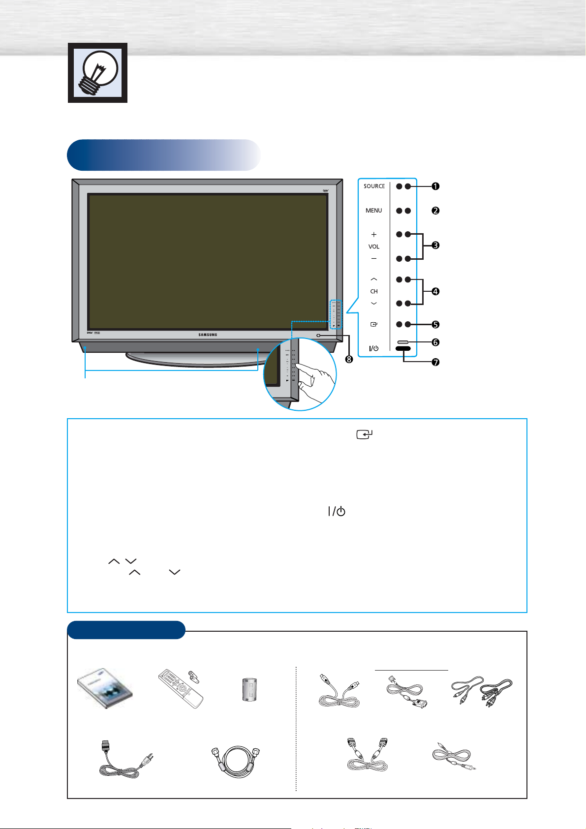
Front Panel
Your New Plasma Display Panel
6
Checking Accessories
Owner’s Instructions
(BN68-00645A)
Once you have unpacked your PDP, check to make sure that you have all the parts shown here.
If any piece is missing or broken, call your dealer.
Remote Control/
AAA Batteries
(BN59-00377D)
Ferrite Core for
Side AV Cable
(
3301-001201
)
Power Cord (3903-000085) Antenna Cable (BN39-00333A)
S-VIDEO Cable
(AA39-40001E)
PC Cable
(BN39-00244A)
DVI Cable
(BN39-00033A)
Component Cables (RCA)
(AA39-00033A)
PC Audio Cable
Sold Separately
ΠSOURCE button
Press to display all of the available video sources
(TV, AV1, AV2, AV3, S-VIDEO1, S-VIDEO2,
COMPONENT1, COMPONENT2, PC, DVI).
´ MENU button
Displays the main on-screen menu.
ˇ VOL(+,-) button
Press to increase or decrease the volume.
Also used to select or adjust items on the
on-screen menu.
¨ CH( , ) button
Press CH or CH to change Channels.
Also used to move up or down in the On-screen
menu.
ˆ ENTER( ) button
Press to confirm a selection.
Ø Power Indicator
- Power Off : Red
- Power On : Off
- Timer On : Green
∏
Press to turn the PDP on and off.
” Remote Control Signal Receiver
Aim the remote control towards this spot on
the PDP.
Speakers
TOUCH button
Press to display all of the
available video sources.
7
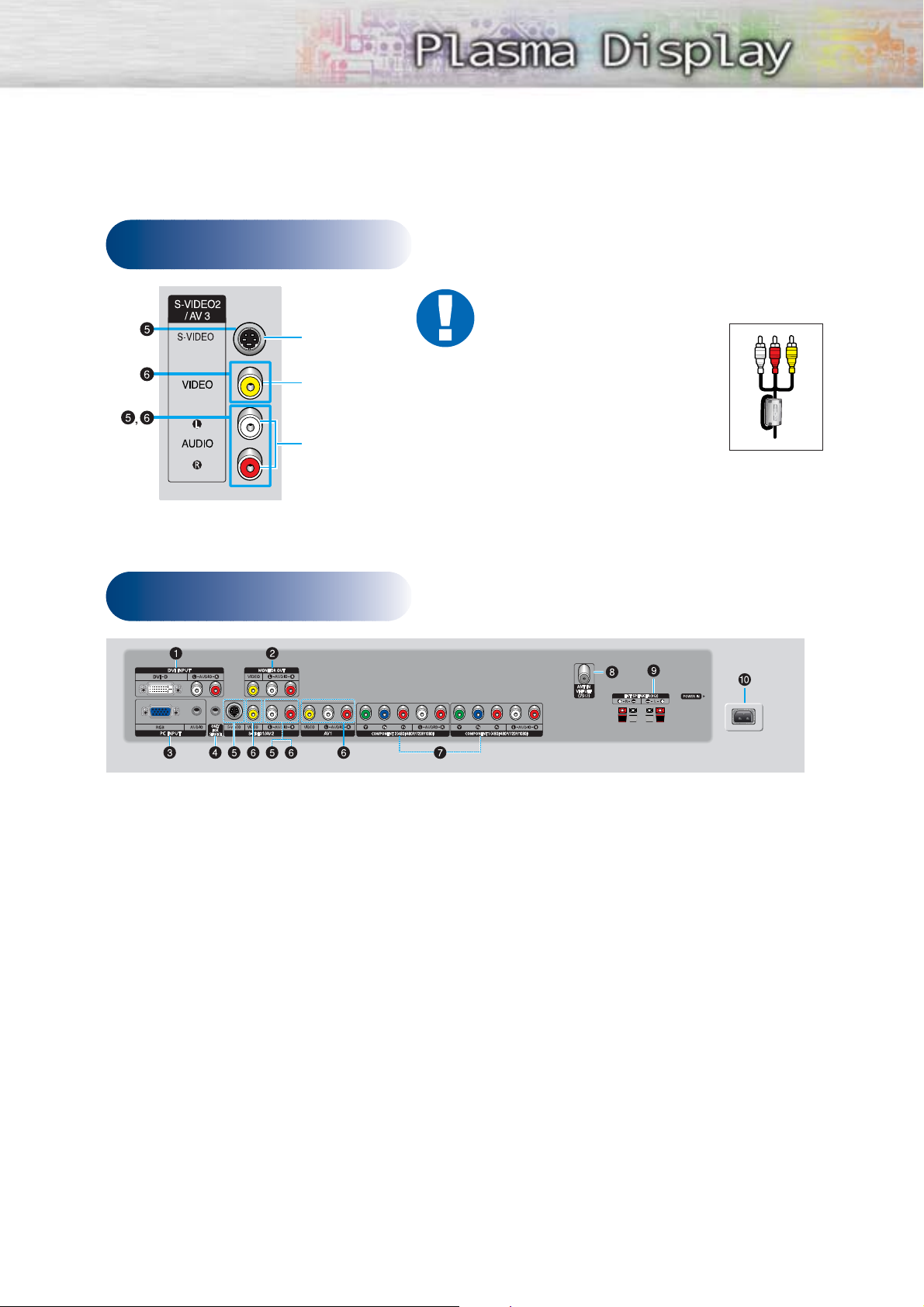
Rear Panel
Side of the TV
ŒDVI INPUT (DVI-D / L-AUDIO-R)
Connect to the digital video and audio
output jack of a device with DVI output.
´MONITOR OUT (VIDEO / L-AUDIO-R)
Outputs for external devices.
ˇPC INPUT (RGB IN / AUDIO)
Connect to the video and audio output
jack on your PC.
¨FOR SERVICE ONLY
Connector for service only.
ˆS-VIDEO1, S-VIDEO2
(S-VIDEO1 or S-VIDEO2 / L-AUDIO-R)
Video and audio inputs for external
devices with an S-Video output, such as
a camcorder or VCR.
ØAV1, AV2, AV3
(VIDEO / L-AUDIO-R )
Video and audio inputs for external
devices, such as a camcorder or VCR.
∏COMPONENT1, COMPONENT2
Video (Y/Pb/Pr) and audio (L-AUDIO-R)
inputs for Component.
”ANT IN VHF/UHF (75Ω)
75Ω Coaxial connector for
Antenna/Cable Network.
’EXT SPEAKER (8Ω)
Connectors for external rear speakers.
˝POWER IN
Connect the supplied power cord.
Audio Input (L, R)
Video Input
S-Video Input
Ferrite Cores
The ferrite cores are used to
attenuate undesired signals. When
connecting cables, attach one of
these ferrite cores to the cable near
the connector.
When you connect Side AV cable
to the AV3/L-AUDIO-R, first bind
Side AV Cable round the ferrite
core to secure it.
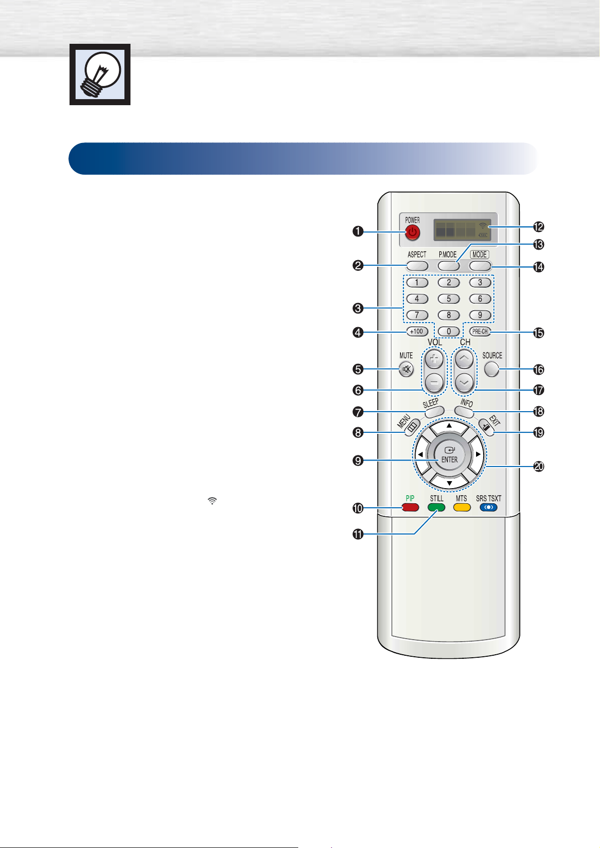
Remote Control Buttons
ŒPOWER button
Turns the PDP on and off.
´ASPECT button
Press to change the screen size.
ˇNumber buttons
¨+100 button
Press to select channels over 100. For example, to select
channel 121, press “+100”, then press “2” and “1.”
ˆMUTE button
Press to mute the PDP sound.
ØVOL (Volume) buttons
Use it to adjust volume.
∏SLEEP button
Press to select a preset time interval for automatic shutoff.
”MENU button
Displays the main on-screen menu.
’ENTER button
Confirms a selection.
˝PIP button
Activates picture in picture.
ÔSTILL button
Press to pause the current screen.
LCD Display
When you press a button, ‘ ‘ appears along with
selected mode (TV, VCR, CATV, DVD or STB) and
the remote's battery charge status.
ÒP.MODE button
Adjust the PDP picture by selecting one of the preset
factory settings (or select your personal, customized
picture settings.)
ÚMODE button
Selects a target device to be controlled by the Samsung
remote control (i.e., VCR, Cable, DVD players or Samsung
STB). If you change modes, the new mode is momentarily
displayed on LCD.
ÆPRE-CH button
Tunes to the previous channel.
ıSOURCE button
Press to display all of the available video sources
(TV, AV1, AV2, AV3, S-VIDEO1, S-VIDEO2, COMPONENT1,
COMPONENT2, PC, DVI).
˜CH (Channel) buttons
Use it to switch channels.
¯INFO button
Press to display information on the PDP screen.
˘EXIT button
Press to exit the menu.
¿Up/Down Left/Right buttons
Control the cursor in the menu.
8
Remote Control
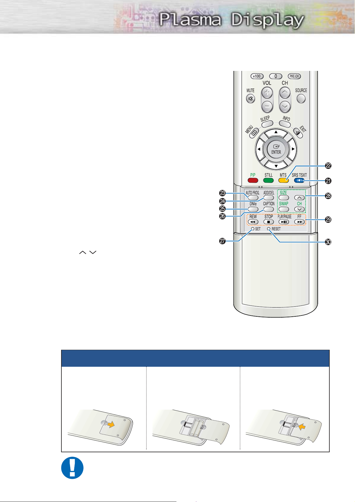
¸SRS TSXT button
Selects Trusurround XT mode.
˛ MTS button
Press to choose stereo, mono or Separate Audio Program (SAP broadcast).
◊AUTO PROG. button
The TV automatically cycles through all of the available channels and stores them in memory.
±ADD/DEL button
Press to add or delete channels in the TV’s memory.
≠DNIe button
Activates DNIe (Digital Natural Image engine).
–CAPTION button
Controls the caption decoder.
—SET button
Used during set up of this Samsung remote control,
so that it will work compatibly with other devices
(VCR, Cable Box, DVD)
÷PIP control buttons
SIZE : Press to make the PIP window Large,
Small or Double.
SWAP : Exchanges the video signal that is
currently displayed on the main screen
with the signal in the PIP window.
CH
,
: Displays the available channels in
sequence. (These buttons change channels
in the PIP window only).
®VCR, DVD control buttons
Controls VCR tape or DVD disc functions: Stop,
Rewind, Play/Pause, Fast Forward.
∑RESET button
If your remote control is not functioning properly, take
out the batteries and press the reset button for about
2~3 seconds. Re-insert the batteries and try using the
remote control again.
9
Installing the Batteries in Your Remote Control
1
Slide the back cover
to open the battery
compartment of the
remote control.
3
Slide the cover back into
place.
2
Install two AAA size batteries. Make sure to match the
“+” and “-” ends of the batteries with the diagram
inside the compartment.
Remote Control Operation Range.
You can use your remote control within a distance of 23 feet and an angle of 30 degrees
from the left and right sides of the PDP’s remote control receiver.
Wall Installation Instructions
This wall mount bracket installation guide is for the following models:HP-P5071
1
Do not install the PDP on any location other than a vertical wall.
2
To protect the performance of the PDP and prevent problems, avoid the following locations:
• Do not install next to smoke and fire detectors.
• Do not install in an area subjected to vibration or high voltage.
• Do not install near or around any heating apparatus.
3
Use only recommended parts and components.
10
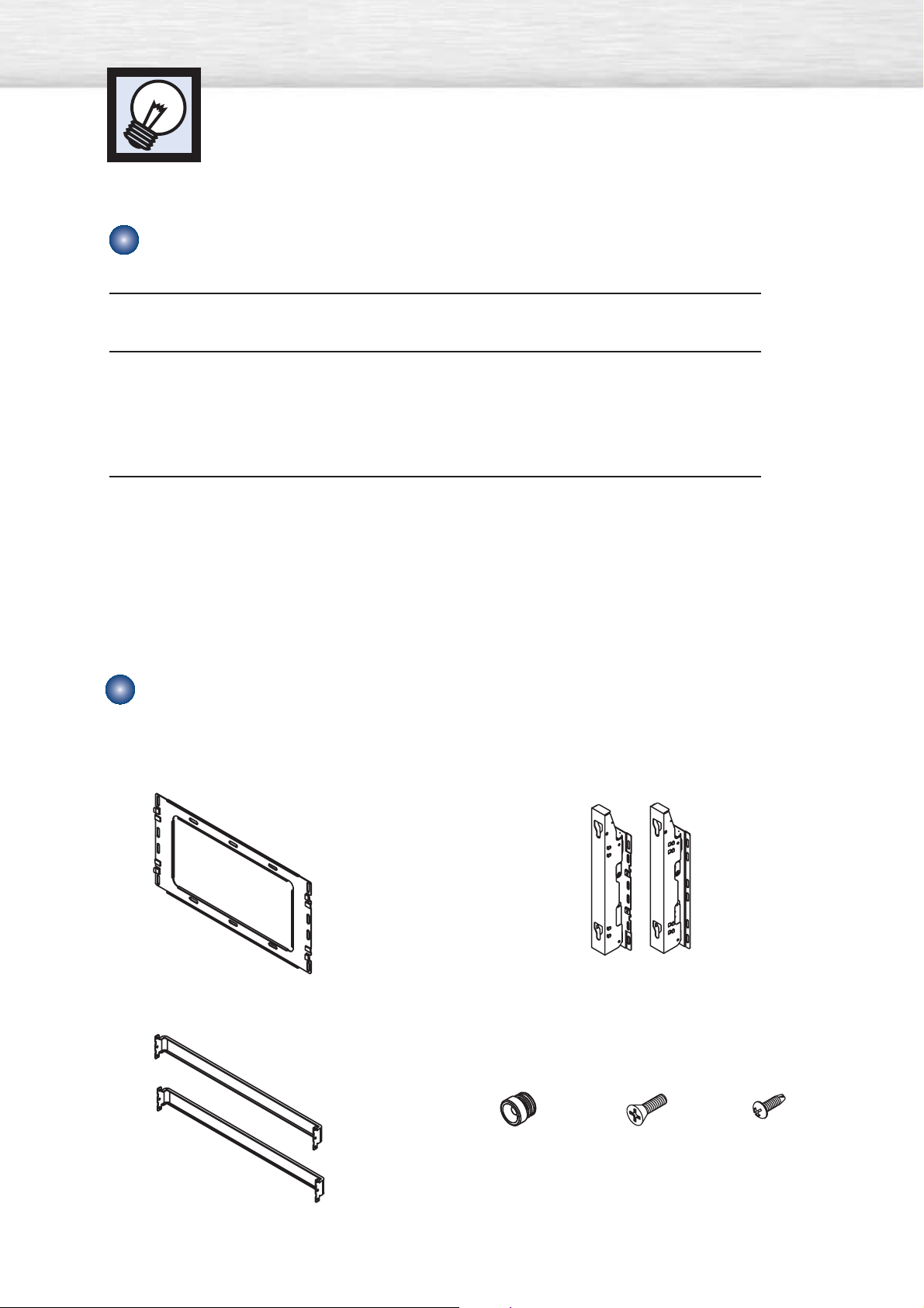
Installation Notes
Insulation Holder :
4 EA
SCREW! : 4 EA SCREW@ : 12 EA
1EA
2EA
LEFT :1EA RIGHT :1EA
Parts (Wall attachment panel is sold separately. Check with your dealer)
Wall Mount Bracket
ASSY-HINGE
Support Bars
Screws
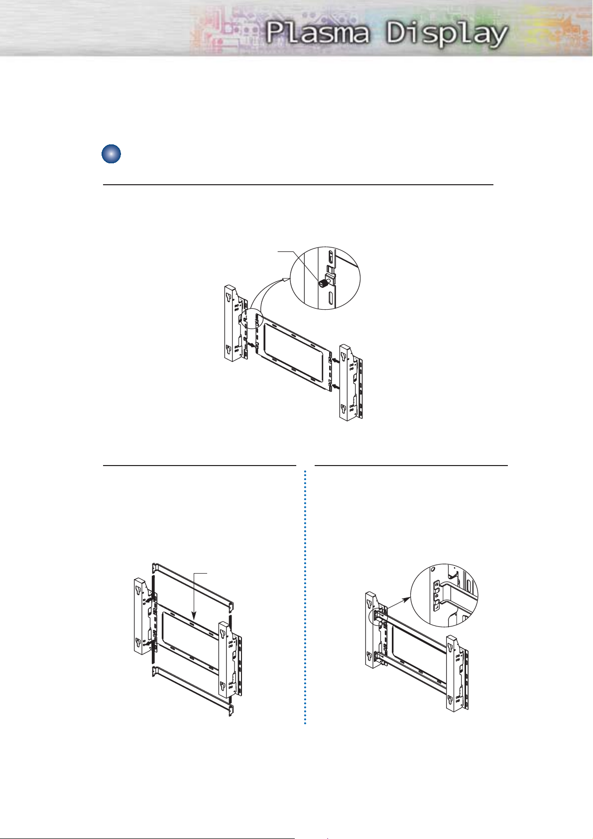
1
The wall mount comes packaged in 3 parts. These parts must be assembled together.
Please tighten the captive screw in the direction of the arrow after assembling
the bracket. Install the Wall Mount Bracket after the screws are securely inserted
into the wall.
2
After installing the Wall Mount Bracket,
assemble the support bars and hinges
(as illustrated) using screws provided.
(12 screws(@) are provided. For safety
reasons, make sure all 12 screws are
firmly attached.)
11
How to assemble the Wall Mount Bracket
ASSY-HINGE (LEFT)
Separate ASSY-HINGE
into Left and Right.
Wall Mount Bracket
Wall Mount Bracket
Support Bars
Support Bars
Captive Screws
ASSY-HINGE
(RIGHT)
ASSY-HINGE
(LEFT)
ASSY-HINGE
(RIGHT)
3
After securing the screws, be sure that
every part is firmly attached (as shown
in the illustration).
ASSY-
HINGE
(LEFT)
ASSY-HINGE
(RIGHT)
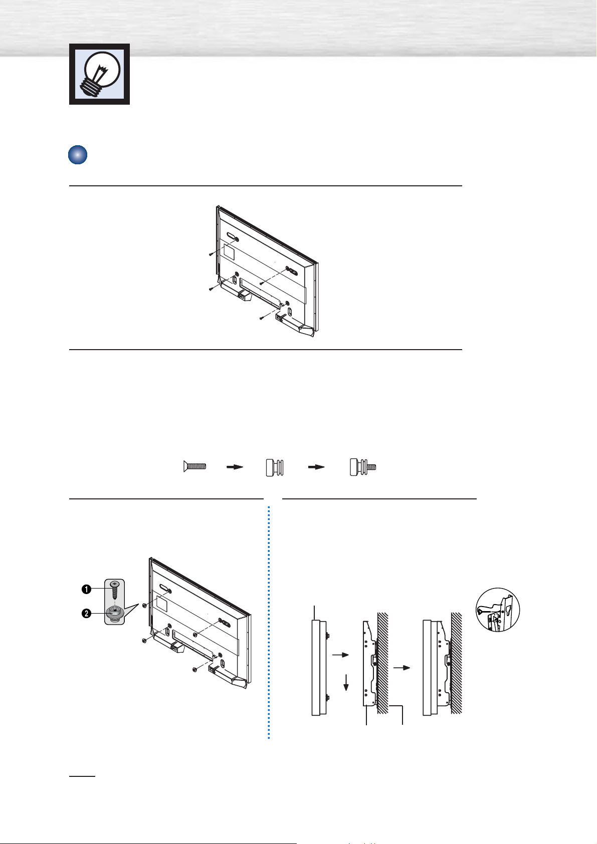
1
Remove the screws from the back of the PDP.
2
Connect insulation holders to screws (see the illustration below).
• If you are uncertain about installation, hire a specialist to install the wall mount bracket.
• Be sure to check that the insulation holders are completely secured on both the left
and right side after hanging the PDP on the wall mount bracket.
• Be careful to avoid getting your fingers caught during installation.
• Make sure the wall attachment panels are tightened. Otherwise the PDP may fall.
Note
•A 5 inch gap is needed between the back of the Plasma TV and the wall.
Wall Installation Instructions
12
Fixing the PDP panel to the wall attachment panel bracket
3
Tighten the screws of the insulation
holders to the back of the PDP.
4
Put the 4 insulation holders on the PDP
in the grooves of the wall mount
bracket and pull down on the PDP (Œ)
to secure it to the wall mount bracket
(´). Tighten the screws as shown (ˇ)
so that the PDP cannot be separated
from wall mount bracket.
PDP panel
Wall attachment panel
bracket
Wall
Œ
´
ˇ
13
Note
• Contact an authorized technician when installing the wall attachment panel.
• After hanging the PDP panel on the wall attachment panel, make sure that the Insulation
holders are completely hung.
• Be careful not to get your fingers caught during installation.
• Make sure the wall attachment panel brackets are tightened. Otherwise, the PDP panel may
fall down.
• Please secure the mounting bracket on the wall surface after setting its angle at 0°.
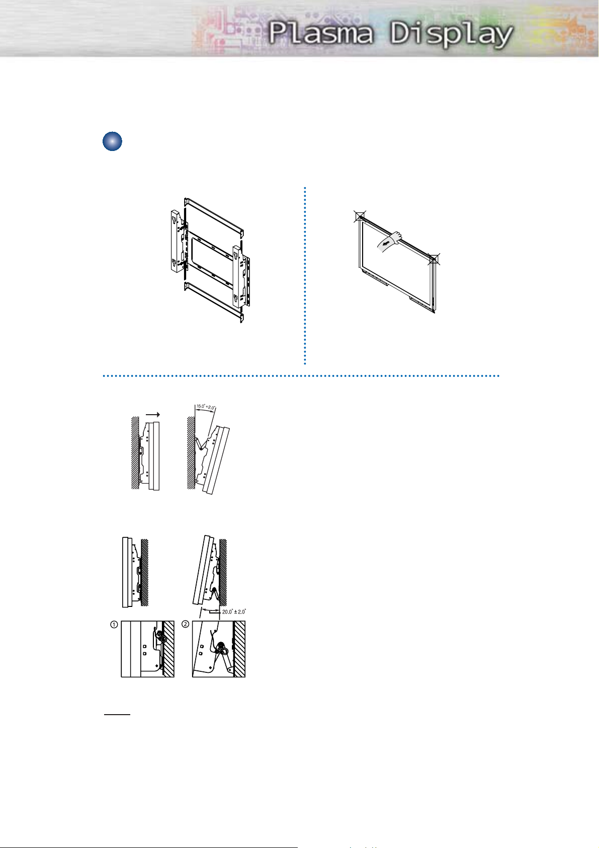
How to Adjust Mounting Angle
Notice
Notice : Please secure the mounting bracket on the wall surface after setting its angle at 0°.
Factory default How to Adjust Mounting Angle
Please tighten the captive screw in the direction
of the arrow after assembling the bracket.
Hold onto the middle of the PDP to adjust
the angle (not the sides of the PDP).
1
Secure the SET to the wall mount bracket.
(Please refer to the following instructions.)
2
Set the angle by pulling the upper end of the SET attached
to bracket in the direction of the arrow.
3
The angle can be adjusted from 0° to 15° by ±2°.
Change Angle
1
Be sure to remove the safety pins underneath the PDP.
(Caution : If the safety pins are not removed, the angle cannot
be adjusted.) Any attempt to do so may cause damage to the PDP.
2
Hold onto the bottom of the PDP and pull forward fully as
directed by the arrow(as illustrated) to adjust the angle.
(0°~20° by 2°). Insert the Safety Pins to the front guide
holes on both sides as illustrated in figure
´
.
3
Viewing the PDP after connecting the external devices.
Remove the Safety Pins to adjust the angle to 0°, and then
secure the Safety Pins again. (Warning : For safety, be sure to
secure the PDP using the safety pins. If the safety pins are not
used, the PDP may fall, causing serious injury.)
Connecting External Devices to the PDP
Installing the Speakers
This speaker installation guide is for the PSN5040 (BN96-00712A) speakers.
The speakers are sold separately.
14
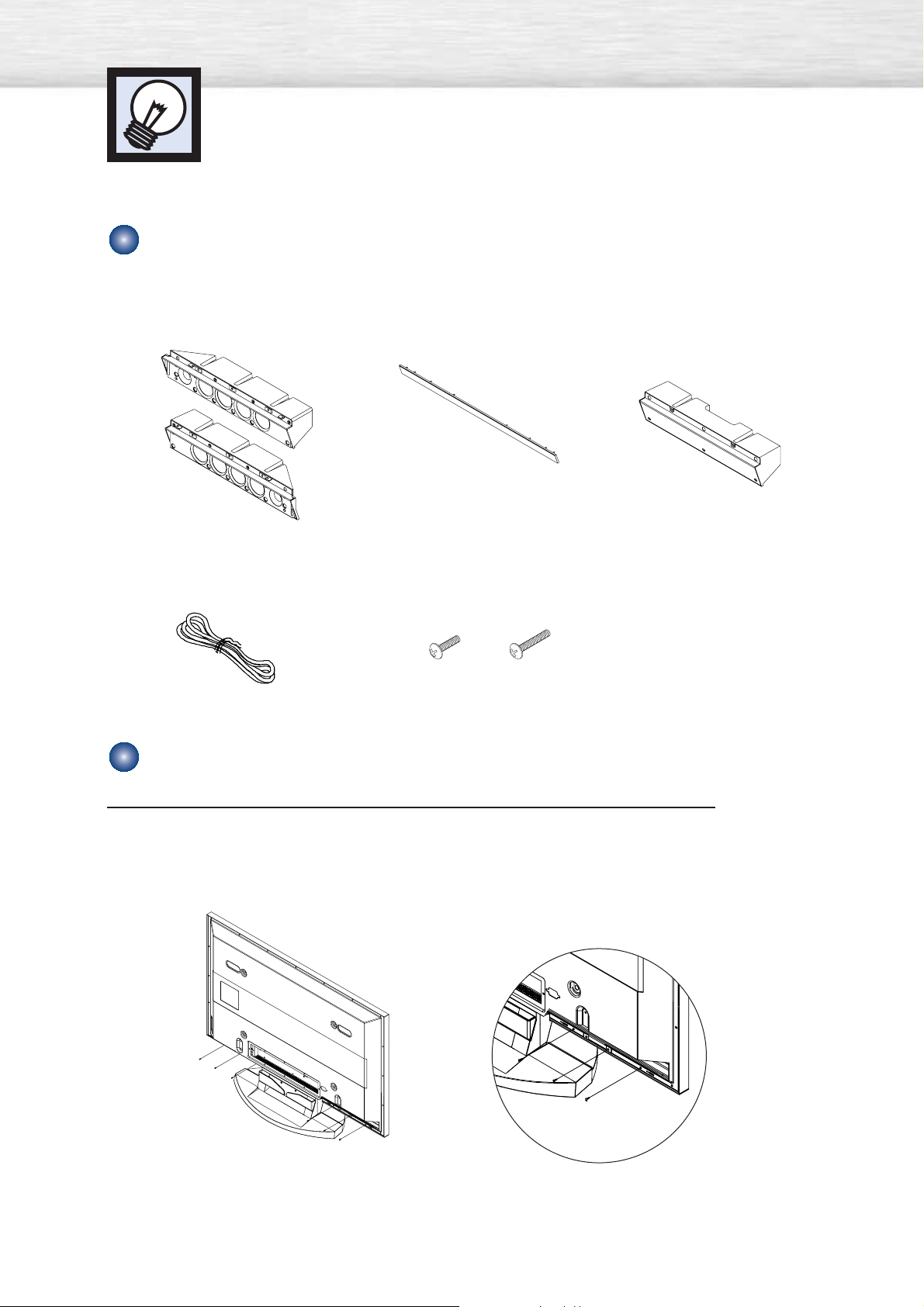
Parts
How to Assemble the Speakers (Standing)
2EA
1EA
1EA
Speakers
1EA
Middle Cabinet
(Wall Mount Only)
Speaker Dust Cover
Speaker Cable
Screw 2EA! Screw 6EA@
Screws
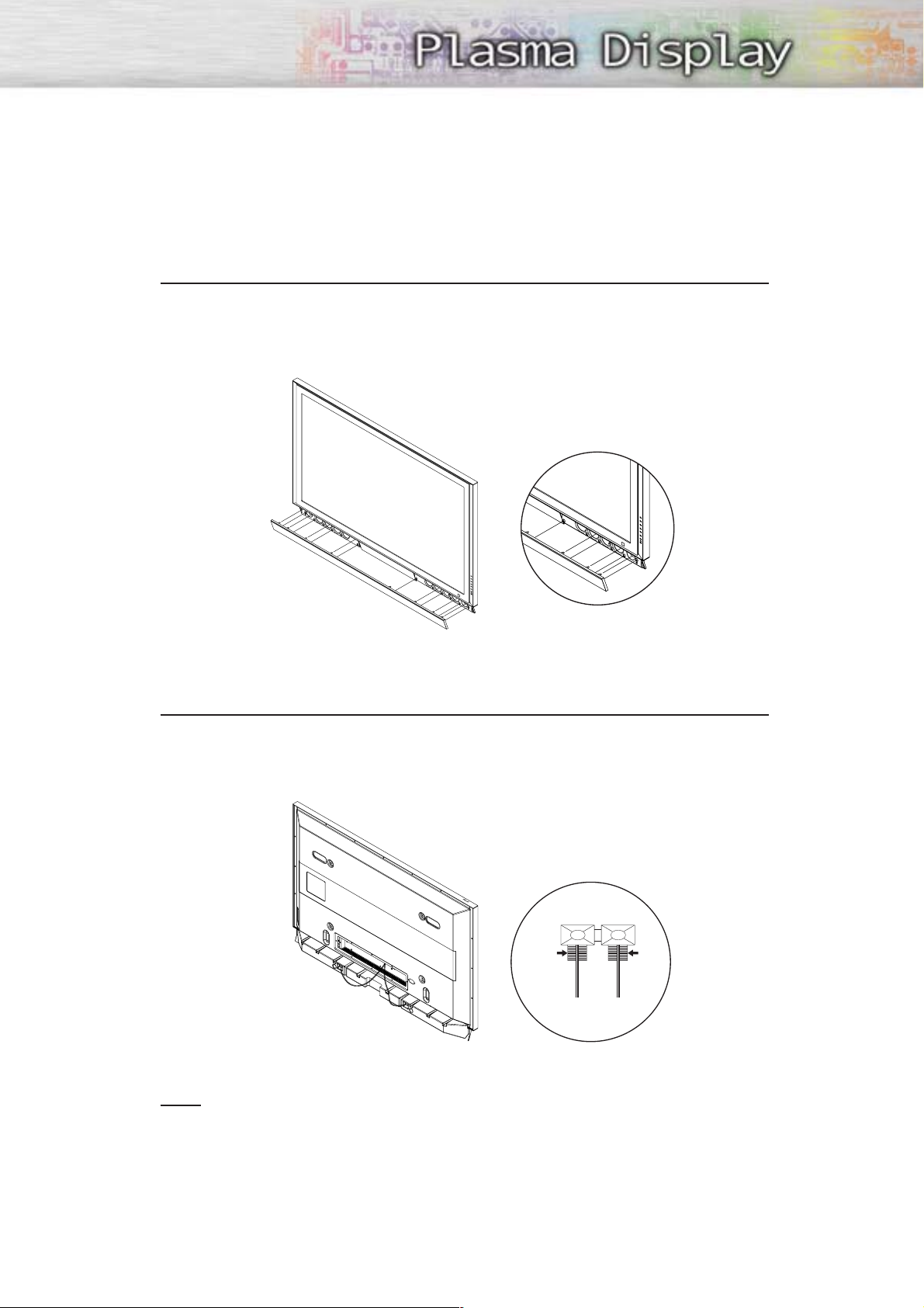
1
Remove the screws indicated on the rear of the PDP (6 screws on the left and right
sides).
15
Screw②
2
Set the Speaker Guide Bracket into the square grooves located on either side of the
PDP’s bottom rear, then push the Speaker Guide Bracket towards the center (as the
arrow illustrates). Secure the Speaker Guide Bracket with provided screws @.
(Always use the proper screws, as indicated.)
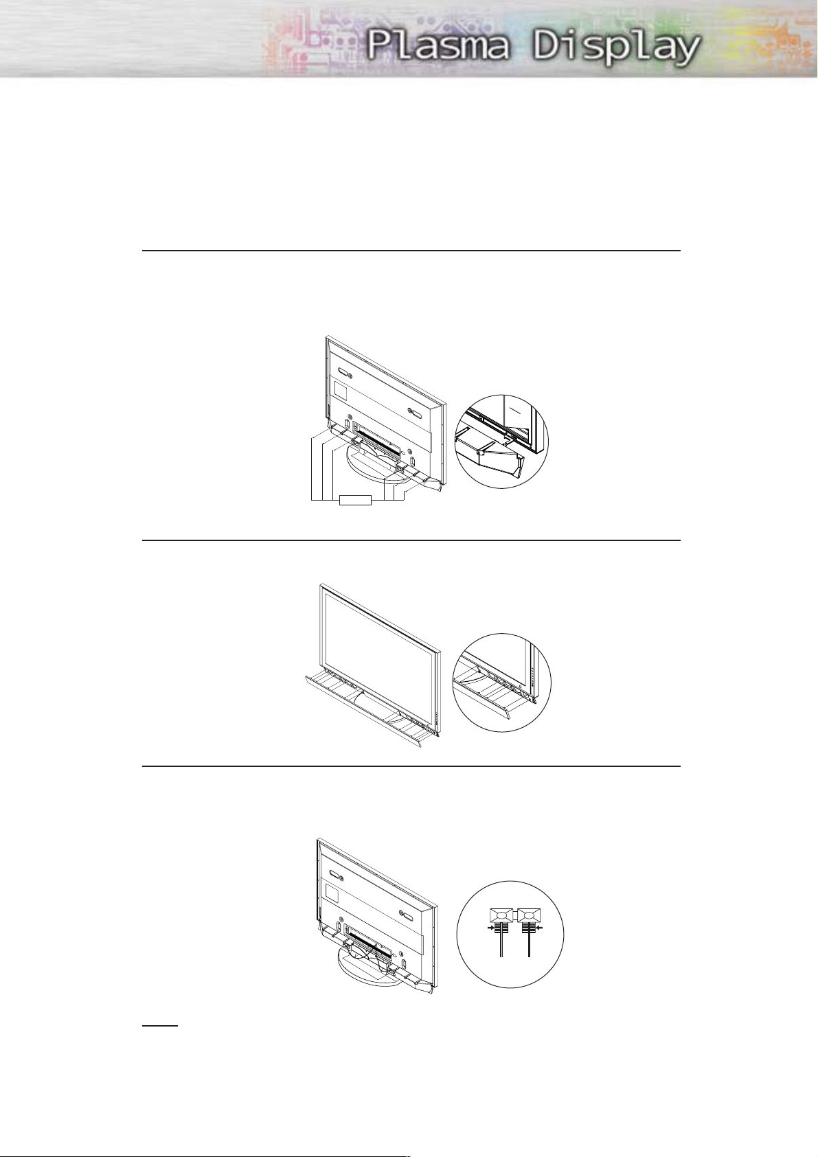
3
Secure the Speaker Dust Cover by setting it into the grooves located on the front side
of the speakers.
4
Connect the speakers to the PDP using the speaker cable.
The connection terminals are on the rear side of both the PDP and the speakers.
(Match the color coded terminals and cables.)
BLACK
BLACK RED
RED
Note
• When moving the PDP with the speakers attached, be sure to hold on to the PDP
to prevent damage. (Damage may occur to the speaker connecting brackets or
the speakers.)
• Speakers of 8Ω Impedance, 15W Nom. Power, 30W Max. Power is recommended.
Installing the Speakers
16
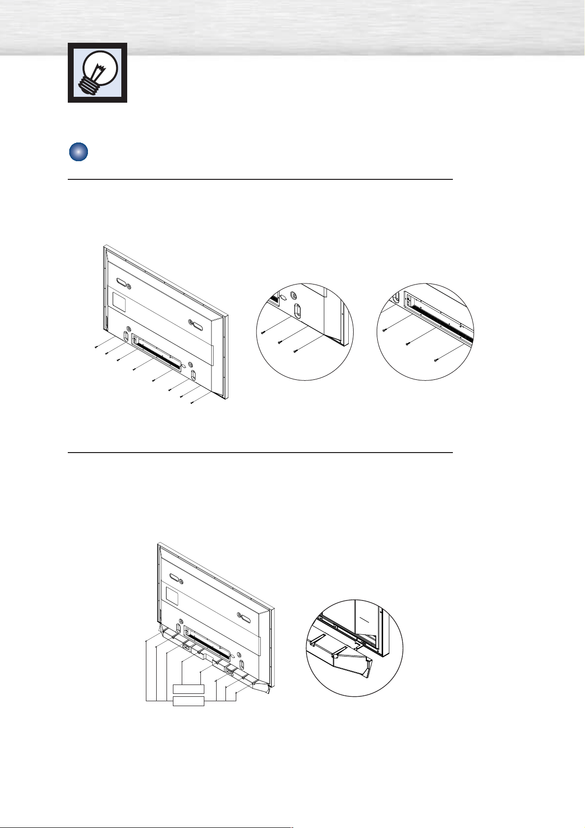
How to Assemble the Speakers (Wall Mount)
1
Remove the screws indicated on the rear of the PDP (6 screws on the left and right
sides, 2 screws on the center).
2
Set the Speaker Guide Bracket into the square grooves located on either side of the
PDP’s bottom rear, then push the Speaker Guide Bracket towards the center (as the
arrow illustrates). Secure the Speaker Guide Bracket with provided screws @.
Secure the Middle Cabinet to the center of the PDP with a screw !.
(Always use the proper screws, as indicated.)
Screw②
Screw①
17
3
Secure the Speaker Dust Cover by setting it into the grooves located on the front side
of the speakers.
4
Connect the speakers to the PDP using the speaker cables.
The connection terminals are on the rear side of both the PDP and the speakers.
(Match the color coded terminals and cables.)
Note
• When moving the PDP with the speakers attached, be sure to hold on to the PDP
to prevent damage. (Damage may occur to the speaker connecting brackets or
the speakers.)
• Speakers are 8Ω Impedance, 15W Nom. Power, 30W Max. Power is recommended.
BLACK
BLACK RED
RED

➤
➤
Two or more people should carry the PDP. Never lay the PDP on the floor because of possible damage to the screen.
Always store the PDP upright.
18
1
Firmly secure the pegs to the both sides of the Stand Base using 8 screws provided.
How to assemble the Stand-Base
2
Using the 4 screws for securing the Stand Pegs and the Monitor, firmly attach the Monitor to the
Stand Pegs. (The exterior of the SET may be different than the picture.)
Warning
Firmly secure the stand for the PDP before
moving it, as the stand may fall and
could cause serious injury.

PLASMA DISPLAY PANEL
Connections
Connecting VHF and UHF Antennas ..............................................20
Connecting Cable TV....................................................................21
Connecting a VCR........................................................................23
Connecting a Camcorder ..............................................................24
Connecting a DVD Player..............................................................25
Connecting a DTV Receiver ..........................................................26
Connecting VHF and UHF Antennas
20
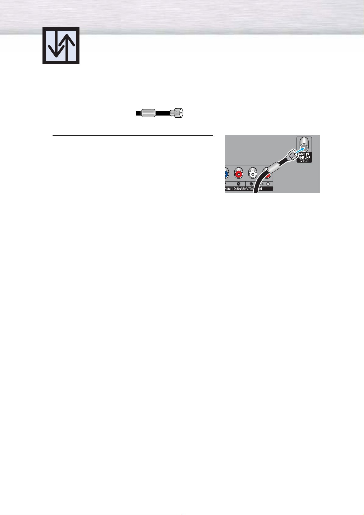
Antennas with 75-ohm Round Leads
If your antenna looks like this: it has 75-ohm round leads.
1
Plug the antenna lead into the VHF/UHF terminal
on the PDP.
Use the Antenna Cable, an accessory included
in the product package.
21
Connecting Cable TV
You can connect different cable systems to your PDP, including cable without a cable box,
and cable with a cable box that descrambles some or all channels.
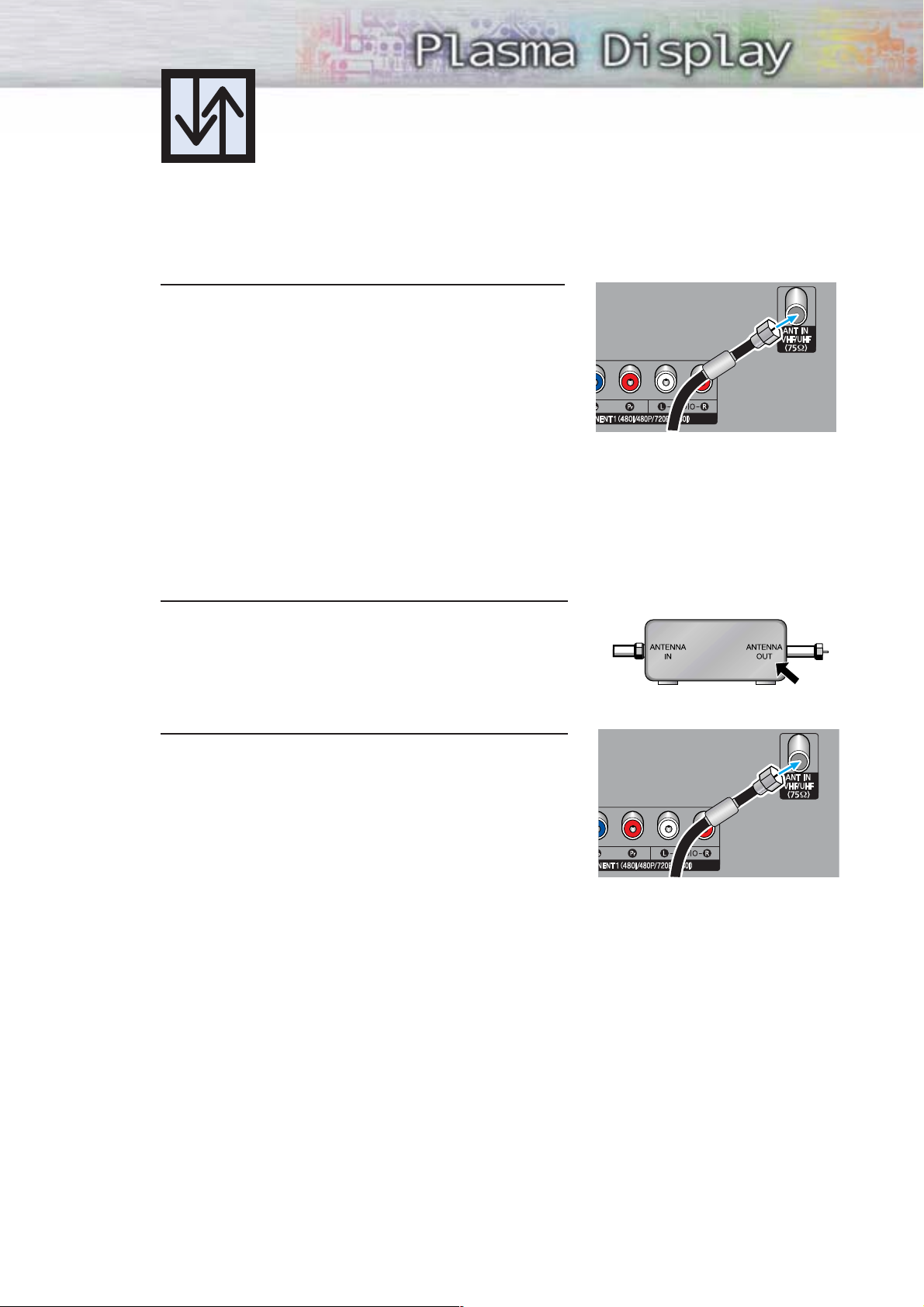
Cable without a Cable Box
1
Plug the incoming cable into the VHF/UHF terminal on
the PDP.
Use the Antenna Cable, an accessory included
in the product package.
Cable with a Cable Box that Descrambles All Channels
1
Find the cable connected to the ANTENNA OUT
terminal on your cable box. This terminal might be
labeled "ANT OUT", "VHF OUT" or simply "OUT".
2
Connect the cable to the VHF/UHF terminal on the
PDP.
Use the Antenna Cable, an accessory included
in the product package.
22
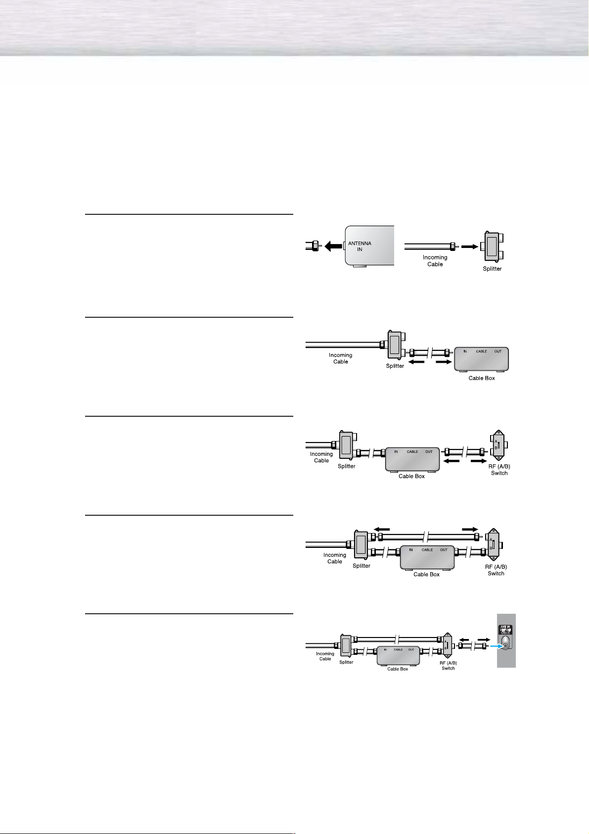
Cable with a Cable Box that Descrambles Some (But Not All) Channels
To complete this connection you will need a two-way splitter, an RF (A/B) switch, and four coaxial
cables (which you can buy from your Samsung dealer or any electronics store).
1
Find and disconnect the cable that is
connected to the ANTENNA IN terminal of
your cable box.
This terminal might be labeled "ANT IN",
"VHF IN" or simply, "IN". Connect this
cable to a two-way splitter.
2
Connect a coaxial cable between an
OUTPUT terminal of the splitter and the
IN terminal of the cable box.
3
Connect a coaxial cable between the
ANTENNA OUT terminal of the cable box
and the B-IN terminal of the A/B switch.
4
Connect a coaxial cable between the
ANTENNA OUT terminal of the cable box
and the B-IN terminal of the A/B switch.
5
Connect the last coaxial cable between the
OUT terminal of the RF (A/B) switch and
the VHF/UHF terminal on the PDP.
After you've made this connection, set the A/B switch to the "A" position for normal viewing.
Set the A/B switch to the "B" position to view scrambled channels. (When you set the A/B switch
to "B", you will need to tune your Set-Top Box to the cable box's output channel, which is usually
channel 3 or 4.)
23
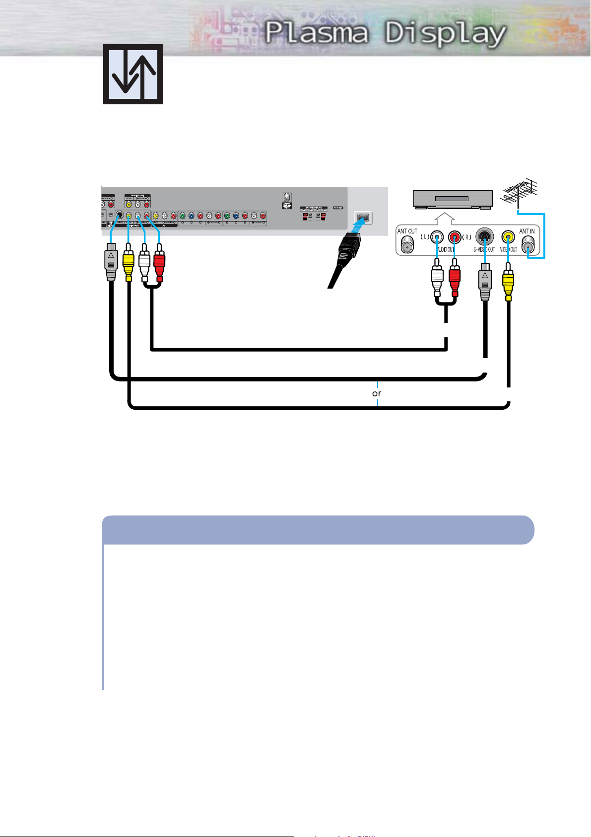
Connecting a VCR
Connecting a VCR to the Video or S-Video/Audio jack
S-Video Cable
Audio Cable
Video Cable
Power Plug
Connect the Video/Audio cables between the VIDEO or S-VIDEO / L - AUDIO - R jacks on the PDP
and VIDEO or S-VIDEO / L - AUDIO - R jacks on the VCR. (Note: For better video, you can use an
S-Video cable.)
Videotape Playback:
1. Turn on your PDP.
2. Press the SOURCE button to select “Video(AV1, AV2 or AV3)” or “S-Video(S-VIDEO1 or
S-VIDEO2)”.
3. Turn on your VCR, insert a videotape and press the play button.
How to Connect
PDP VCR

24
Connecting a Camcorder
Audio Cable
Video Cable
Power Plug
Connect a Video/Audio cable between the VIDEO / L - AUDIO - R jacks on the PDP and
the VIDEO/AUDIO OUTPUT jacks on the camcorder.
Viewing Tapes
1. Turn on your PDP.
2. Press the SOURCE button to select “Video(AV1, AV2 or AV3)”.
3. Turn on your camcorder and set it to Video Mode. (For details, refer to your camcorder
Owner’s instructions.)
4. Set the IN/OUT switch on your camcorder to OUT.
5. Insert the tape into the camcorder and press the Play button.
How to Connect
Viewing camcorder tapes
PDP
Camcorder
25
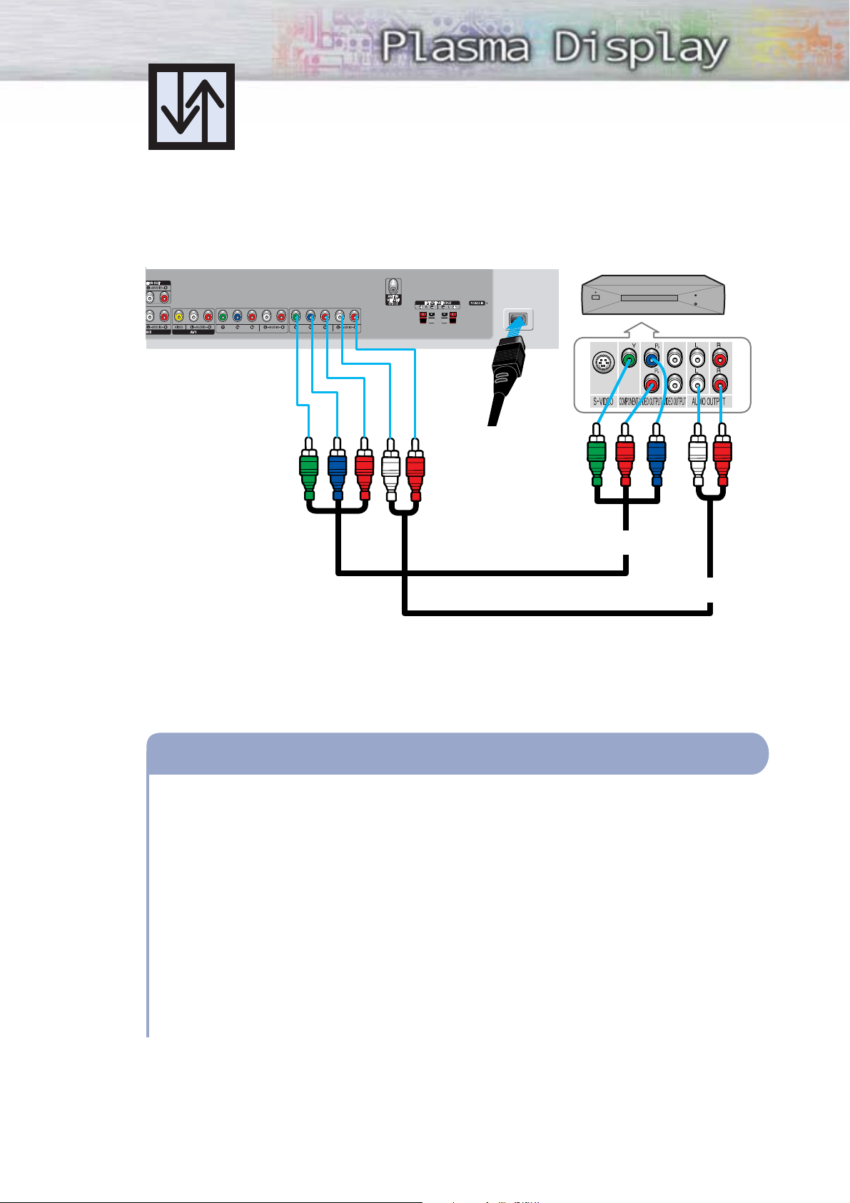
Connecting a DVD Player (480i, 480p)
This PDP displays the optimum picture in 720p mode.
Playing DVD
Audio Cable
Video Cable
Power Plug
Connect a Video Cable between the Y, Pb, Pr(COMPONENT1, 2) input jacks on the PDP
and Y/P
B/PR
output jacks on the DVD player.
Connect a Audio Cable between the AUDIO L/R(COMPONENT1, 2) input jacks on the PDP
and the AUDIO OUT jacks on the DVD player.
To Play DVD:
1. Turn on your PDP.
2. Press the SOURCE button to select “COMPONENT1” or “COMPONENT2”.
3. Turn on your DVD player, insert a DVD disc and press the Play button.
• For an explanation of Component video, see your DVD owner’s instructions.
How to Connect
1
2
PDP DVD Player
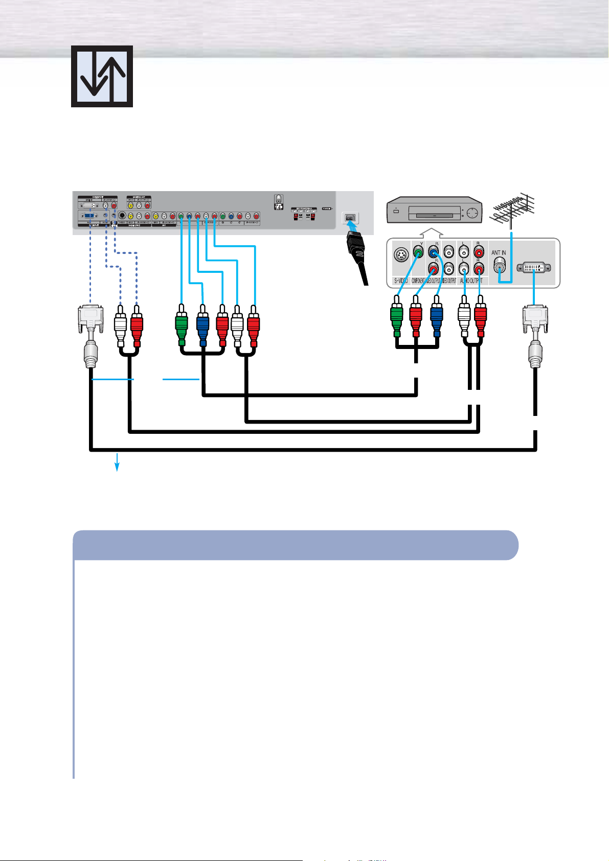
Connecting a DTV Receiver
(480p, 720p, 1080i)
This PDP displays the optimum picture in 720p mode.
26
Watching DTV
Video Cable
Audio Cable
DVI Cable
or
Power
Plug
Connect the cable or antenna to the antenna input jack on the DTV.
Connect a Video cable between the Y, P
b
, Pr(COMPONENT 1, 2) or DVI jack on the PDP
and the Y, P
B
, PR(VIDEO OUTPUT JACKS) on the DTV receiver.
Connect an Audio cable between the COMPONENT 1, 2 (L/R AUDIO) or DVI jacks on the
PDP and the AUDIO OUTPUT jacks on the DTV receiver.
To Watch DTV:
1. Turn on your PDP.
2. Press the SOURCE button to select “COMPONENT1”, “COMPONENT2” or “DVI”.
3. Turn on your DTV receiver.
• For an explanation of Component video, see your DTV receiver owner’s instructions.
How to Connect
1
2
3
Use a DVI-D connection cable. (sold separately)
PDP
DTV Receiver

PLASMA DISPLAY PANEL
Operation
Turning the PDP On and Off ..........................................................28
Plug & Play Feature ......................................................................30
Memorizing the Channels..............................................................33
Setting Up Your Remote Control ....................................................38
Viewing an External Signal Source ................................................40
Turning the PDP On and Off
28
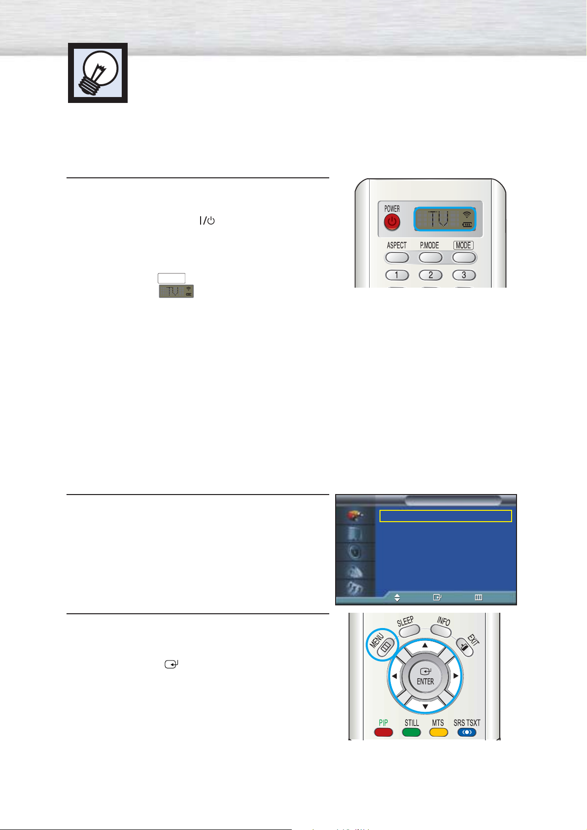
Turning the PDP On and Off
Press the POWER button on the remote control.
The PDP will be turned on and you will be ready to use its
features.
You can also use the POWER ( )button on the front of the
PDP.
Notes:
• If your PDP isn’t turned on when the power button is
pressed: Press the
MODE
button to check if the TV mode
has been chosen ( ).
Viewing the Menus and Displays
Your PDP has a simple, easy-to-use menu system that appears on the PDP screen. This system makes it
convenient and fast to use features on the PDP. Your PDP also lets you display the status of many of your
PDP’s features.
Viewing the Menus
1
With the power on, press the MENU button on the
remote control. The main menu appears on the screen.
The Input menu is selected.
2
Press the ▲ or ▼ buttons to move to items in the menu.
Press the œ/√/ENTER buttons to display, change, or
use the selected items.
Press the ENTER ( ) button to enter items in the menu.
On screen menus disappear from the screen
automatically after about thirty seconds, or you can
press the MENU or EXIT button on your remote control
to exit the menu.
Source List : TV √
Edit Name √
Input
TV
Move Enter Return

29
Displaying Status Information
Press the INFO button on the remote control.
The PDP will display the Picture mode, Sound mode, MTS,
Caption, and Clock.
Air 4
Mono
V-Chip
Picture : Custom
Sound : Custom
MTS : Stereo
Clock : 12 : 00 am
CC
30
Plug & Play Feature
When the television is initially powered ON, several basic customer settings proceed
automatically and subsequently. The following settings are available.
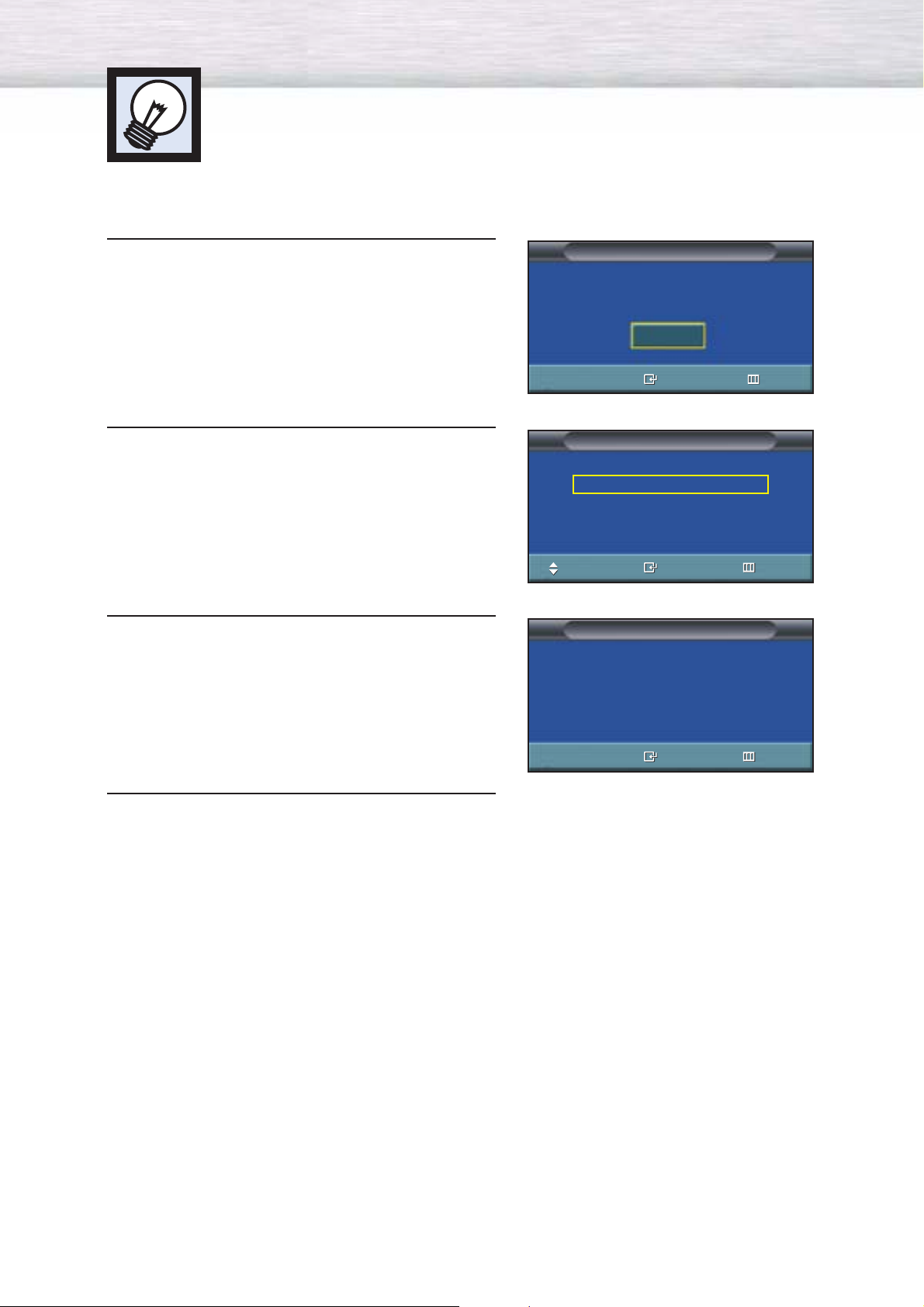
1
If the television is in Standby mode, press the
POWER button on the remote control.
2
Select the appropriate language by pressing the
▲ or ▼ button.
3
Press the ENTER button to confirm your choice.
4
Press the ENTER button.
➤
➤
The message Start Plug & Play is displayed. It flickers for a little
while, and then the Language menu is automatically displayed.
➤
➤
The message Check antenna input is displayed.
Language
Move Enter Skip
English
Français
Español
Plug & Play
Enter Skip
Check antenna input.
Start Plug & Play
Start
Plug & Play
Enter Exit
 Loading...