

Page 1
Owner’s Instructions
HP-P5031
This device is a Class B digital apparatus.
Page 2

Important Warranty Information
Regarding Television Format Viewing
Wide screen format PDP Displays (16:9,the aspect ratio of the screen width to height) are primarily
designed to view wide screen format full-motion video. The images displayed on them should primarily be
in the wide screen 16:9 ratio format,or expanded to fill the screen if your model offers this feature and the
images are constantly moving. Displaying stationary graphics and images on screen, such as the dark
side-bars on nonexpanded standard format television video and programming, should be limited to no
more than 5% of the total television viewing per week.
Additionally,viewing other stationary images and text such as stock market reports, video game
displays,station logos,web sites or computer graphics and patterns,should be limited as described above
for all televisions. Displaying stationary images that exceed the above guidelines can
cause uneven aging of PDP Displays that leave subtle,but permanent burned-in
ghost images in the PDP picture. To avoid this,vary the programming and images,
and primarily display full screen moving images,not stationary patterns or dark bars.
On PDP models that offer picture sizing features,use these controls to view different formats as a full screen
picture.
Be careful in the selection and duration of television formats used for viewing. Uneven PDP aging as a
result of format selection and use,as well as burned-in images, are not covered by your Samsung limited
warranty.
User Instructions
Screen Image retention
Do not display a still image (such as on a video game or when hooking up a PC to this PDP) on the plasma
display panel for more than several minutes as it can cause screen image retention. This image retention is
also known as “screen burn”. To avoid such image retention, refer to page 44 of this manual to reduce the
degree of brightness and contrast of this screen when displaying a still image.
Cell Defect
The plasma display panel consists of fine cells. Although the panels are produced with more than 99.9
percent active cells, there may be some cells that do not produce light or remain lit.
Altitude
The PDP will not operate normally at altitudes above 6500 ft.
Warranty
Warranty does not cover any damage caused by image retention.
Burn-in is not covered by the warranty.
2
Page 3

Table of Contents
General Information
Your New Plasma Display Panel ......................6
Remote Control Buttons ..................................8
Wall Installation Instructions ..........................10
Connecting Speakers ..................................14
How to assemble the Stand-Base ..................16
Connections
Connecting VHF and UHF Antennas ..............18
Connecting Cable TV ..................................19
Connecting a VCR ......................................21
Connecting a Camcorder ............................22
Connecting a DVD Player ............................23
Connecting a DTV Receiver ..........................24
Operation
Turning the PDP On and Off ........................26
Sound Control
Customizing the Sound ................................62
Using Automatic Sound Settings ...................63
Choosing a Multi-Channel Sound (MTS)Soundtrack
Using the Auto Volume ................................65
Setting the TruSurround XT ............................66
Listening to the Sound of the Sub(PIP) Picture ..67
Selecting the Internal Mute............................68
......64
Channel Control
Fine Tuning Channels ..................................70
LNA (Low Noise Amplifier) ..........................71
Connecting a PC and Operation
Connecting a PC ........................................74
Adjusting the PC Screen ..............................78
Changing the Position of the Image................79
Plug & Play Feature......................................28
Memorizing the Channels ............................31
Setting Up Your Remote Control ....................36
Viewing an External Signal Source ..............38
Picture Control
Customizing the Picture ..............................42
Using Automatic Picture Settings ..................43
Selecting the Color Tone ..............................44
DNIe (Digital Natural Image engine) ............45
Changing the Screen Size ..........................46
Freezing the Picture ...................................48
Viewing the Picture-in-Picture .......................49
Selecting a Signal Source (Antenna or Cable) for PIP
Setting the MCC(My Control Color) Mode .....56
.....54
Picture Quality Adjustment ..........................80
Information ................................................83
Time Setting
Setting the Clock ........................................86
Setting the Sleep Timer ................................87
Setting the Timers ........................................88
Function Description
Selecting a Menu Language ........................92
Digital Noise Reduction ..............................93
Selecting the Film Mode ..............................94
Using the Color Weakness Enhancement Option
Setting the Melody Sound ............................96
Setting the Blue Screen ................................97
Viewing Closed Captions ............................98
Using the V-Chip..........................................99
..95
Appendix
Troubleshooting ........................................106
Care and Maintenance ..............................107
Specifications............................................108
3
Page 4

Page 5

PLASMA DISPLAY PANEL
General Information
Your New Plasma Display Panel ......................................................6
Remote Control Buttons ..................................................................8
Wall Installation Instructions ..........................................................10
Connecting Speakers....................................................................14
How to assemble the Stand-Base ....................................................16
Page 6
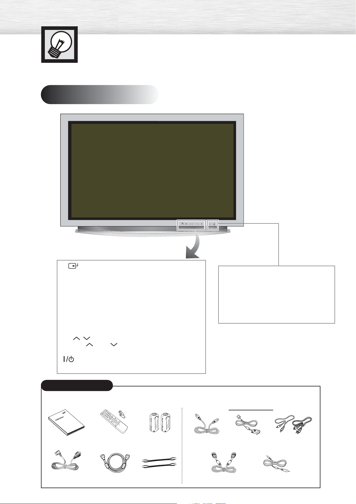
Your New Plasma Display Panel
Front Panel
SOURCE/ENTER button
Press to display all of the available video sources
(ie., TV, AV1, AV2, S-Video, Component1, Component2,
PC, DVI).
Press to confirm a selection.
MENU button
Displays the main on-screen menu and exit.
VOL(+,-) button
Press to increase or decrease the volume. Also used
to select or adjust items on the on-screen menu.
CH(
Press
Also used to move up or down in the On-screen menu.
Press to turn the PDP on and off.
,
) button
CH or CH
to change Channels.
Power Indicator
- Power Off: Red
- Power On: Off
- Timer On : Green
Remote Control Signal Receiver
Aim the remote control towards this spot
on the PDP.
Checking Accessories
Once you have unpacked your PDP, check to make sure that you have all the parts shown here.
If any piece is missing or broken, call your dealer.
Owner’s Instructions
Remote Control (BN59-00377G)/
AAA Batteries (4301-000103)
Ferrite Core 2EA
(3301-001110)
S-VIDEO Cable
(AA39-40001E)
Sold Separately
DVI Cable
(BN39-00072A)
Component Cables (RCA)
(AA39-00033A)
6
Power Cord
(3903-000144)
Antenna Cable
(BN39--00333A)
Speaker Cables
(BN39-00530A)
PC Cable
(AA39-00288A)
PC Audio Cable
(BH39-00120A)
Page 7
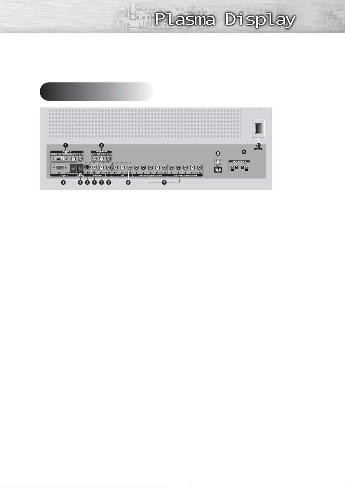
Rear Panel
ŒDVI INPUT (DVI-D / L-AUDIO-R)
Connect to the digital video and audio
output jack of a device with DVI output.
´MONITOR OUT (VIDEO / L-AUDIO-R)
Outputs for external devices.
ˇPC INPUT (RGB IN / AUDIO)
Connect to the video and audio output
jack on your PC.
¨FOR SERVICE ONLY
Connector for service only.
ˆS-VIDEO
(S-VIDEO / L-AUDIO-R)
Video and audio inputs for external
devices with an S-Video output, such as
a camcorder or VCR.
ØAV1, AV2
(VIDEO / L-AUDIO-R )
Video and audio inputs for external
devices, such as a camcorder or VCR.
∏COMPONENT1, COMPONENT2
Video (Y/Pb/Pr) and audio (L-AUDIO-R)
inputs for Component.
”ANT IN VHF/UHF (75Ω)
75Ω Coaxial connector for
Antenna/Cable Network.
’EXT SPEAKER (8Ω)
Connectors for external rear speakers.
˝POWER IN
Connect the supplied power cord.
7
Page 8

Remote Control Buttons
Remote Control
ŒPOWER button
Turns the PDP on and off.
´ASPECT button
Press to change the screen size.
ˇNumber buttons
¨+100 button
Press to select channels over 100. For example, to select
channel 121, press “+100”, then press “2” and “1.”
ˆMUTE button
Press to mute the PDP sound.
ØVOL (Volume) buttons
Use it to adjust volume.
∏SLEEP button
Press to select a preset time interval for automatic shutoff.
”MENU button
Displays the main on-screen menu.
’ENTER button
Confirms a selection.
˝PIP button
Activates picture in picture.
ÔSTILL button
Press to pause the current screen.
LCD Display
When you press a button, ‘ ‘ appears along with
selected mode (TV, VCR, CATV, DVD or STB) and
the remote's battery charge status.
ÒP.MODE button
Adjust the PDP picture by selecting one of the preset
factory settings (or select your personal, customized
picture settings.)
ÚMODE button
Selects a target device to be controlled by the Samsung
remote control (i.e., VCR, Cable, DVD players or Samsung
STB). If you change modes, the new mode is momentarily
displayed on LCD.
ÆPRE-CH button
Tunes to the previous channel.
ıSOURCE button
Press to display all of the available video sources
(TV, AV1, AV2 S-VIDEO, COMPONENT1, COMPONENT2,
PC, DVI).
˜CH (Channel) buttons
Use it to switch channels.
¯INFO button
Press to display information on the PDP screen.
˘EXIT button
Press to exit the menu.
¿Up/Down Left/Right buttons
8
Control the cursor in the menu.
Page 9

¸SRS TSXT button
Selects Trusurround XT mode.
˛ MTS button
Press to choose stereo, mono or Separate Audio Program (SAP broadcast).
◊AUTO PROG. button
The TV automatically cycles through all of the available channels and stores them in memory.
±ADD/DEL button
Press to add or delete channels in the TV’s memory.
≠DNIe button
Activates DNIe (Digital Natural Image engine).
–CAPTION button
Controls the caption decoder.
—SET button
Used during set up of this Samsung remote control,
so that it will work compatibly with other devices
(VCR, Cable Box, DVD)
÷PIP control buttons
SIZE : Press to make the PIP window Large,
Small or Double.
SWAP : Exchanges the video signal that is
currently displayed on the main screen
with the signal in the PIP window.
,
CH
: Displays the available channels in
sequence. (These buttons change channels
in the PIP window only).
®VCR, DVD control buttons
Controls VCR tape or DVD disc functions: Stop,
Rewind, Play/Pause, Fast Forward.
∑RESET button
If your remote control is not functioning properly, take
out the batteries and press the reset button for about
2~3 seconds. Re-insert the batteries and try using the
remote control again.
Installing the Batteries in Your Remote Control
Slide the back cover
1
to open the battery
compartment of the
remote control.
Install two AAA size batter-
2
ies. Make sure to match the
“+” and “-” ends of the batteries with the diagram
inside the compartment.
Slide the cover back into
3
place.
Remote Control Operation Range.
You can use your remote control within a distance of 23 feet and an angle of 30 degrees
from the left and right sides of the PDP’s remote control receiver.
9
Page 10
Wall Installation Instructions
This wall mount bracket installation guide is for the following models:HP-P5031
Installation Notes
Do not install the PDP on any location other than a vertical wall.
1
To protect the performance of the PDP and prevent problems, avoid the following locations:
2
• Do not install next to smoke and fire detectors.
• Do not install in an area subjected to vibration or high voltage.
• Do not install near or around any heating apparatus.
Use only recommended parts and components.
3
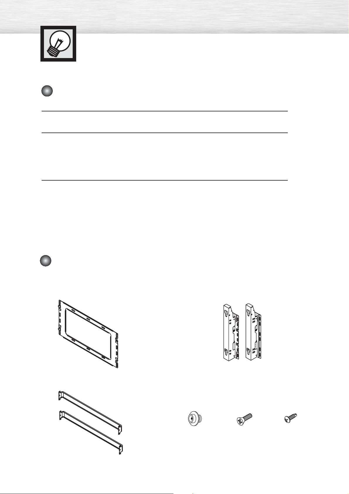
Parts (Wall attachment panel is sold separately. Check with your dealer)
Wall Mount Bracket
1EA
Support Bars
Screws
Insulation Holder :
4 EA
2EA
ASSY-HINGE
LEFT :1EA RIGHT :1EA
SCREW! : 4 EA SCREW@ : 12 EA
10
Page 11
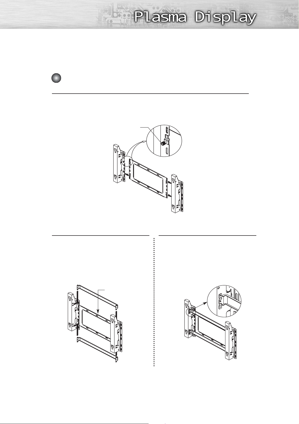
How to assemble the Wall Mount Bracket
The wall mount comes packaged in 3 parts. These parts must be assembled together.
Please tighten the captive screw in the direction of the arrow after assembling
1
the bracket. Install the Wall Mount Bracket after the screws are securely inserted
into the wall.
Captive Screws
ASSY-HINGE (LEFT)
Wall Mount Bracket
Separate ASSY-HINGE
into Left and Right.
ASSY-HINGE
(RIGHT)
2
ASSY-HINGE
(LEFT)
Support Bars
After installing the Wall Mount Bracket,
assemble the support bars and hinges
(as illustrated) using screws provided.
(12 screws(@) are provided. For safety
reasons, make sure all 12 screws are
firmly attached.)
Wall Mount Bracket
Support Bars
ASSY-HINGE
(RIGHT)
After securing the screws, be sure that
every part is firmly attached (as shown
3
in the illustration).
ASSY-
HINGE
(LEFT)
ASSY-HINGE
(RIGHT)
11
Page 12

Wall Installation Instructions
Fixing the PDP panel to the wall attachment panel bracket
Remove the screws from the back of the PDP.
1
Connect insulation holders to screws (see the illustration below).
2
• If you are uncertain about installation, hire a specialist to install the wall mount bracket.
• Be sure to check that the insulation holders are completely secured on both the left
and right side after hanging the PDP on the wall mount bracket.
• Be careful to avoid getting your fingers caught during installation.
• Make sure the wall attachment panels are tightened. Otherwise the PDP may fall.
Tighten the screws of the insulation
holders to the back of the PDP.
3
Put the 4 insulation holders on the PDP
in the grooves of the wall mount
4
bracket and pull down on the PDP (Œ)
to secure it to the wall mount bracket
(´). Tighten the screws as shown (ˇ)
so that the PDP cannot be separated
from wall mount bracket.
PDP panel
Œ
´
Wall attachment panel
bracket
Note
•A 5 inch gap is needed between the back of the Plasma TV and the wall.
ˇ
Wall
12
Page 13
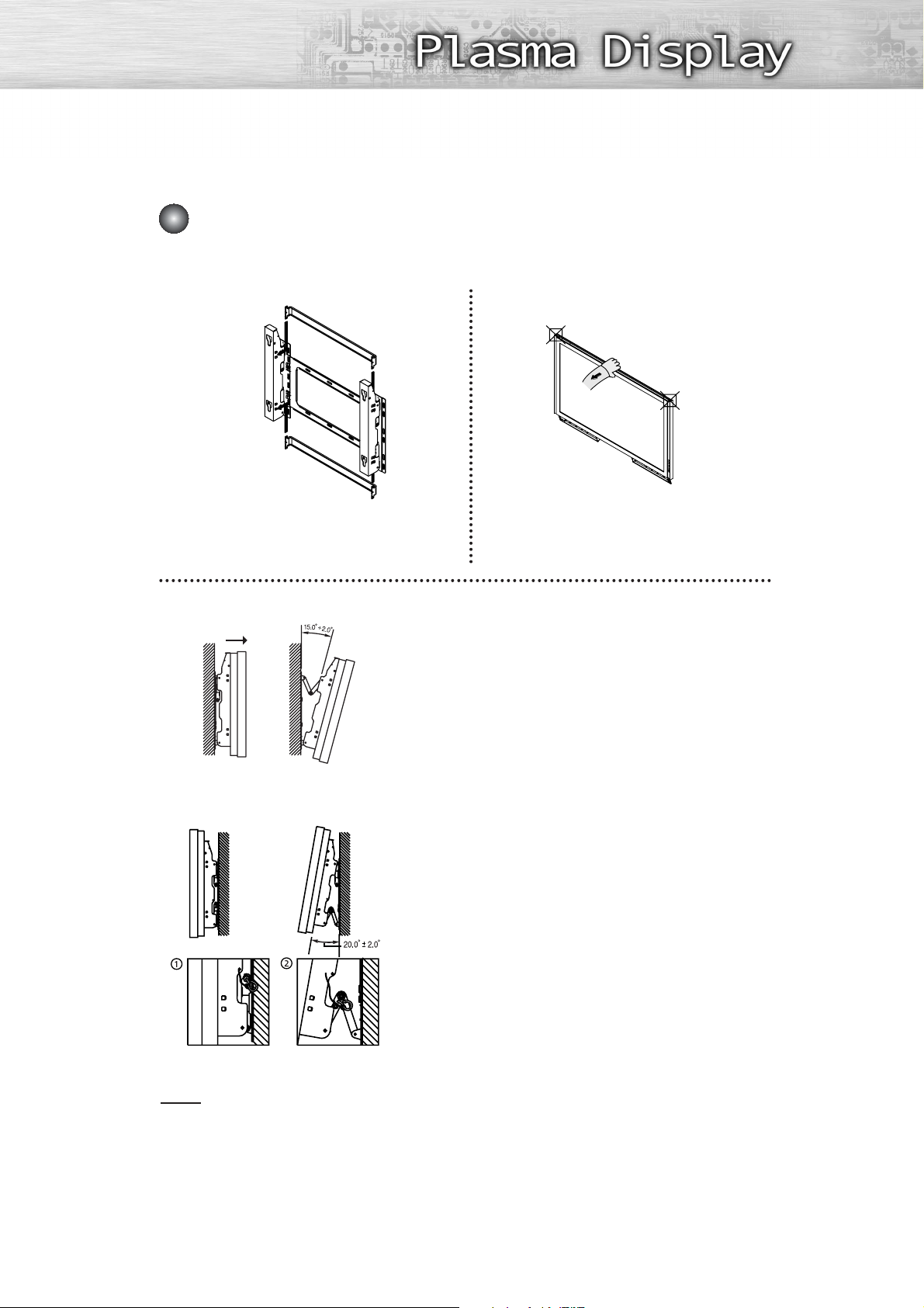
How to Adjust Mounting Angle
Notice : Please secure the mounting bracket on the wall surface after setting its angle at 0°.
Notice
Factory default How to Adjust Mounting Angle
Please tighten the captive screw in the direction
of the arrow after assembling the bracket.
Change Angle
Secure the SET to the wall mount bracket.
(Please refer to the following instructions.)
1
Set the angle by pulling the upper end of the SET attached
to bracket in the direction of the arrow.
2
The angle can be adjusted from 0° to 15° by ±2°.
3
Connecting External Devices to the PDP
Be sure to remove the safety pins underneath the PDP.
(Caution : If the safety pins are not removed, the angle cannot
1
be adjusted.) Any attempt to do so may cause damage to the PDP.
Hold onto the bottom of the PDP and pull forward fully as
directed by the arrow(as illustrated) to adjust the angle.
2
(0°~20° by 2°). Insert the Safety Pins to the front guide
holes on both sides as illustrated in figure
Hold onto the middle of the PDP to adjust
the angle (not the sides of the PDP).
.
´
Viewing the PDP after connecting the external devices.
Remove the Safety Pins to adjust the angle to 0°, and then
3
secure the Safety Pins again. (Warning : For safety, be sure to
secure the PDP using the safety pins. If the safety pins are not
used, the PDP may fall, causing serious injury.)
Note
• Contact an authorized technician when installing the wall attachment panel.
• After hanging the PDP panel on the wall attachment panel, make sure that the Insulation
holders are completely hung.
• Be careful not to get your fingers caught during installation.
• Make sure the wall attachment panel brackets are tightened. Otherwise, the PDP panel may
fall down.
• Please secure the mounting bracket on the wall surface after setting its angle at 0°.
13
Page 14
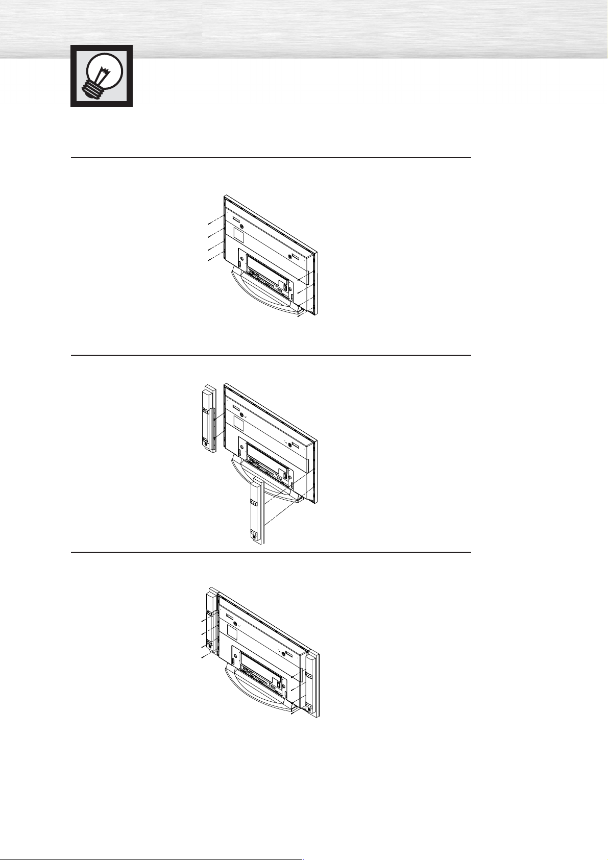
Connecting Speakers
Remove the screws on the rear of the PDP.
1
Hang the two “T” shaped hangers on the square holes on the rear of the PDP.
2
14
Tighten the PDP and the speaker bracket using the screws removed from the PDP.
3
When moving your PDP, do NOT hold the speaker connected to your PDP. It may damage the bracket
➤
➤
clamping the speaker and your PDP together and result in a drop of your PDP and a risk of personal
damage and injury.
Page 15

Connect the speaker audio cable to the external speaker output jack on the rear of the PDP matching the
“+” and “-” ends of the cable with the diagram on the PDP.
The speakers MUST have to a power handling capability of 10 watts minimum (impedance 8Ω).
➤
➤
When you connect the speaker wire to the external speaker out connector, first bind the speaker wire round the ferrite core to secure it.
Ferrite Cores
The ferrite cores are used to attenuate undesired signals.
When connecting cables, attach one of these ferrite cores to the cable
near the connector.
15
Page 16
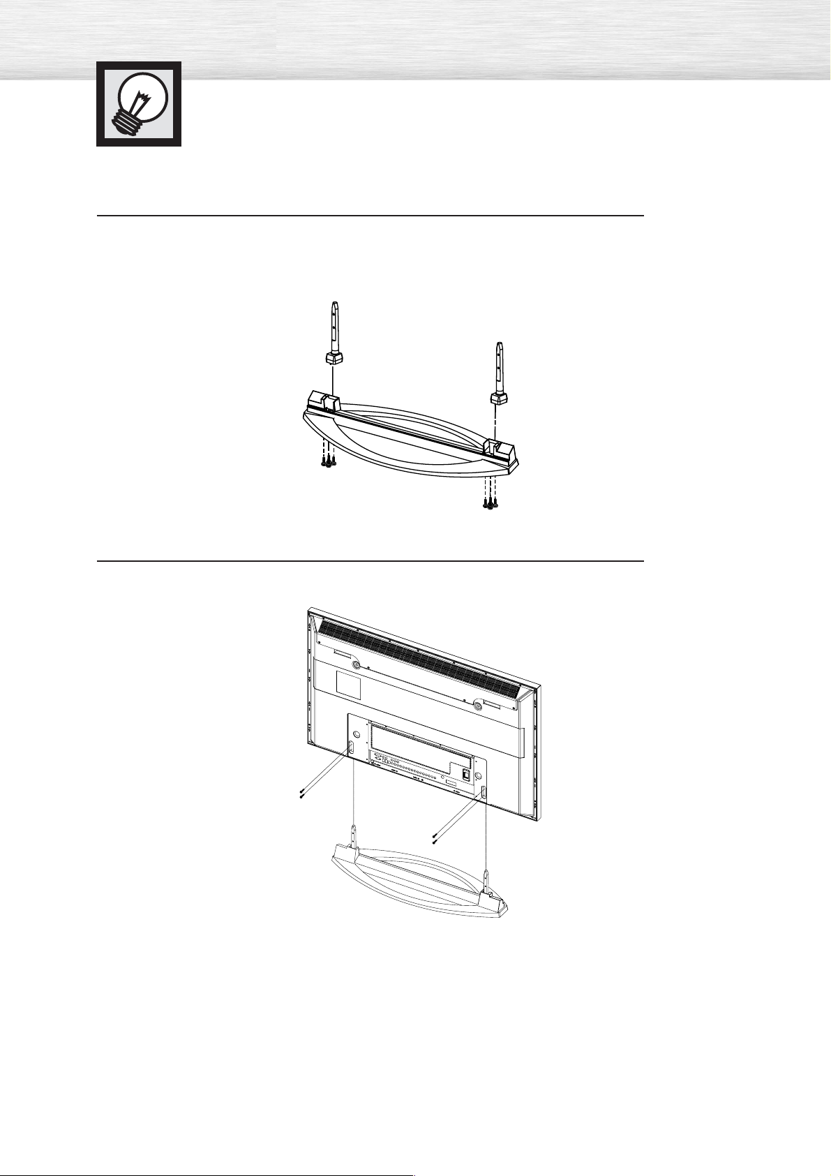
How to assemble the Stand-Base
Assemble two support pins with the stand base and firmly secure both sides of the
support pins using 8 screws provided.
1
Assemble the PDP with the stand and firmly secure the PDP using 4 screws provided.
2
Two or more people should carry the PDP. Never lay the PDP on the floor because of possible damage
➤
➤
to the screen. Always store the PDP upright.
16
Page 17

PLASMA DISPLAY PANEL
Connections
Connecting VHF and UHF Antennas ..............................................18
Connecting Cable TV....................................................................19
Connecting a VCR........................................................................21
Connecting a Camcorder ..............................................................22
Connecting a DVD Player..............................................................23
Connecting a DTV Receiver ..........................................................24
Page 18
Connecting VHF and UHF Antennas
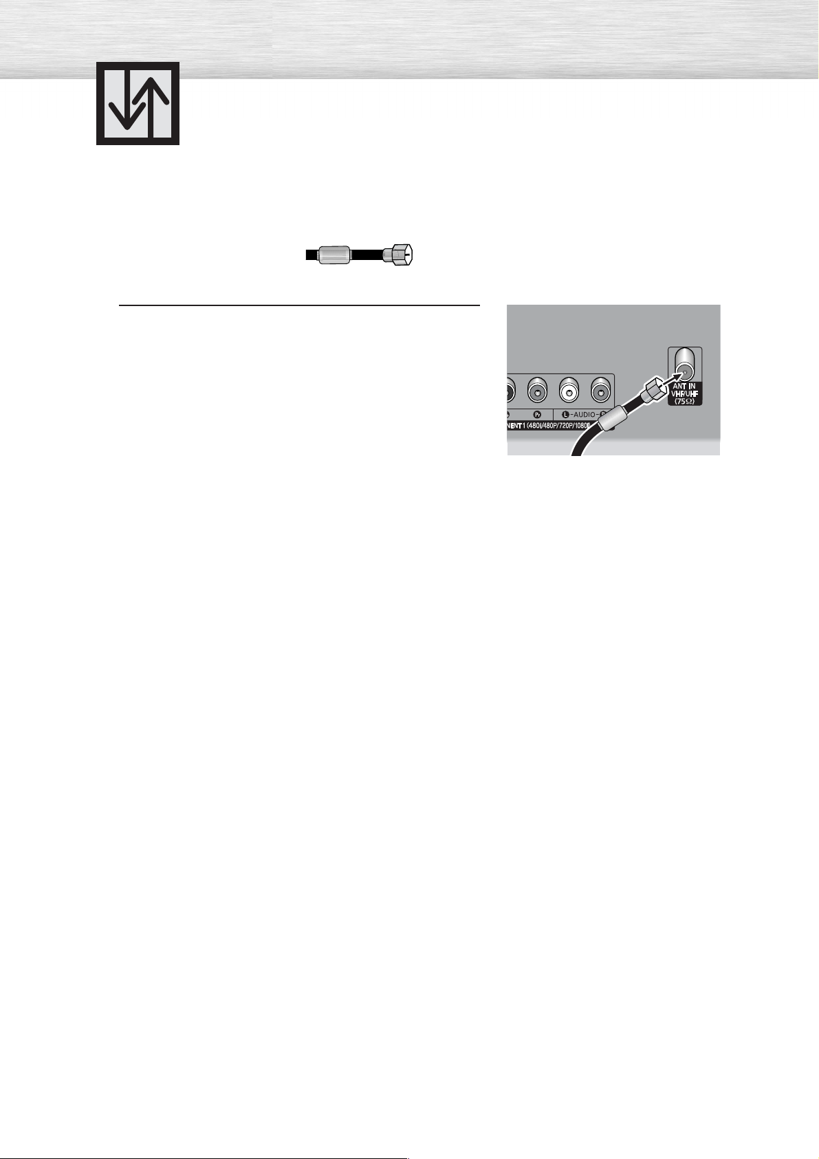
Antennas with 75-ohm Round Leads
If your antenna looks like this: it has 75-ohm round leads.
Plug the antenna lead into the VHF/UHF terminal
on the PDP.
1
Use the Antenna Cable, an accessory included
in the product package.
18
Page 19

Connecting Cable TV
You can connect different cable systems to your PDP, including cable without a cable box,
and cable with a cable box that descrambles some or all channels.
Cable without a Cable Box
Plug the incoming cable into the VHF/UHF terminal on
the PDP.
1
Use the Antenna Cable, an accessory included
in the product package.
Cable with a Cable Box that Descrambles All Channels
Find the cable connected to the ANTENNA OUT
terminal on your cable box. This terminal might be
1
labeled "ANT OUT", "VHF OUT" or simply "OUT".
Connect the cable to the VHF/UHF terminal on the
PDP.
2
Use the Antenna Cable, an accessory included
in the product package.
19
Page 20

Cable with a Cable Box that Descrambles Some (But Not All) Channels
To complete this connection you will need a two-way splitter, an RF (A/B) switch, and four coaxial
cables (which you can buy from your Samsung dealer or any electronics store).
Find and disconnect the cable that is
connected to the ANTENNA IN terminal of
1
your cable box.
This terminal might be labeled "ANT IN",
"VHF IN" or simply, "IN". Connect this
cable to a two-way splitter.
Connect a coaxial cable between an
OUTPUT terminal of the splitter and the
2
IN terminal of the cable box.
Connect a coaxial cable between the
ANTENNA OUT terminal of the cable box
3
and the B-IN terminal of the A/B switch.
20
Connect a coaxial cable between the
ANTENNA OUT terminal of the cable box
4
and the B-IN terminal of the A/B switch.
Connect the last coaxial cable between the
OUT terminal of the RF (A/B) switch and
5
the VHF/UHF terminal on the PDP.
After you've made this connection, set the A/B switch to the "A" position for normal viewing.
Set the A/B switch to the "B" position to view scrambled channels. (When you set the A/B switch
to "B", you will need to tune your Set-Top Box to the cable box's output channel, which is usually
channel 3 or 4.)
Page 21
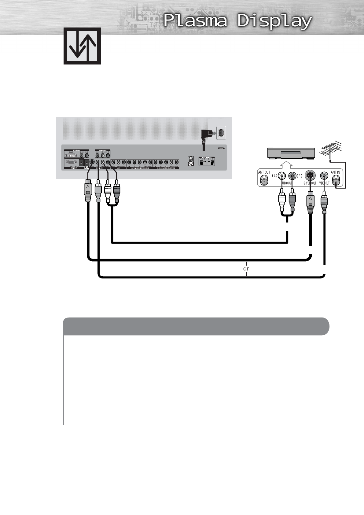
Connecting a VCR
Connecting a VCR to the Video or S-Video/Audio jack
PDP
Power Plug
VCR
Audio Cable
S-Video Cable
Video Cable
How to Connect
Connect the Video/Audio cables between the VIDEO or S-VIDEO / L - AUDIO - R jacks on the PDP
and VIDEO or S-VIDEO / L - AUDIO - R output jacks on the VCR. (Note: For better video, you can use
an S-Video cable.)
Videotape Playback:
1. Turn on your PDP.
2. Press the SOURCE button to select “Video(AV1 or AV2)” or “S-Video.
3. Turn on your VCR, insert a videotape and press the play button.
21
Page 22

Connecting a Camcorder
S-VIDEO
Viewing camcorder tapes
PDP
Camcorder
Power Plug
Video Cable
Audio Cable
How to Connect
Connect a Video/Audio cable between the VIDEO or S-VIDEO / L - AUDIO - R jacks on the PDP
and the VIDEO or S-VIDEO / AUDIO output jacks on the camcorder.
Viewing Tapes
1. Turn on your PDP.
2. Press the SOURCE button to select “Video(AV1 or AV2)” or “S-VIDEO”.
3. Turn on your camcorder and set it to Video Mode. (For details, refer to your camcorder
Owner’s instructions.)
4. Set the IN/OUT switch on your camcorder to OUT.
5. Insert the tape into the camcorder and press the Play button.
22
Page 23
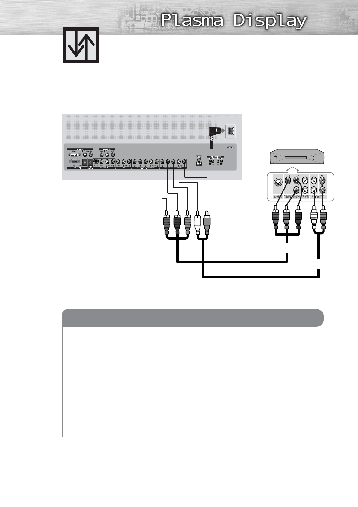
Connecting a DVD Player
This PDP displays the optimum picture in 720p mode.
Playing DVD
PDP
(480i, 480p)
Power Plug
DVD Player
Video Cable
How to Connect
Connect a Video Cable between the Y, Pb, Pr(COMPONENT1, 2) input jacks on the PDP
1
and Y/PB/PRoutput jacks on the DVD player.
Connect a Audio Cable between the AUDIO L/R(COMPONENT1, 2) input jacks on the PDP
2
and the AUDIO output jacks on the DVD player.
To Play DVD:
1. Turn on your PDP.
2. Press the SOURCE button to select “COMPONENT1” or “COMPONENT2”.
3. Turn on your DVD player, insert a DVD disc and press the Play button.
• For an explanation of Component video, see your DVD owner’s instructions.
Audio Cable
23
Page 24
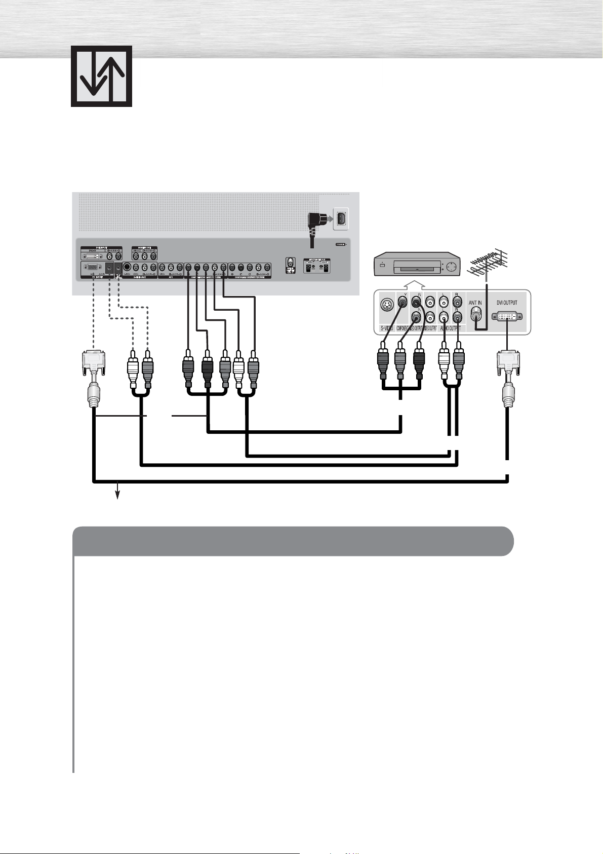
Connecting a DTV Receiver
(480p, 720p, 1080i)
This PDP displays the optimum picture in 720p mode.
Watching DTV
PDP
Power Plug
DTV Receiver
or
Video Cable
Audio Cable
Use a DVI-D connection cable. (sold separately)
How to Connect
Connect the cable or antenna to the antenna input jack on the DTV.
1
Connect a Video cable between the Y, Pb, Pr(COMPONENT 1, 2) or DVI jack on the PDP
2
and the Y, PB, PR(COMPONENT) or DVI output jacks on the DTV receiver.
Connect an Audio cable between the COMPONENT 1, 2 (L/R AUDIO) or DVI (L/R AUDIO)
3
jacks on the PDP and the AUDIO output jacks on the DTV receiver.
To Watch DTV:
DVI Cable
24
1. Turn on your PDP.
2. Press the SOURCE button to select “COMPONENT1”, “COMPONENT2” or “DVI”.
3. Turn on your DTV receiver.
• For an explanation of Component video, see your DTV receiver owner’s instructions.
Page 25

PLASMA DISPLAY PANEL
Operation
Turning the PDP On and Off ..........................................................26
Plug & Play Feature ......................................................................28
Memorizing the Channels..............................................................31
Setting Up Your Remote Control ....................................................36
Viewing an External Signal Source ................................................38
Page 26
Turning the PDP On and Off
Turning the PDP On and Off
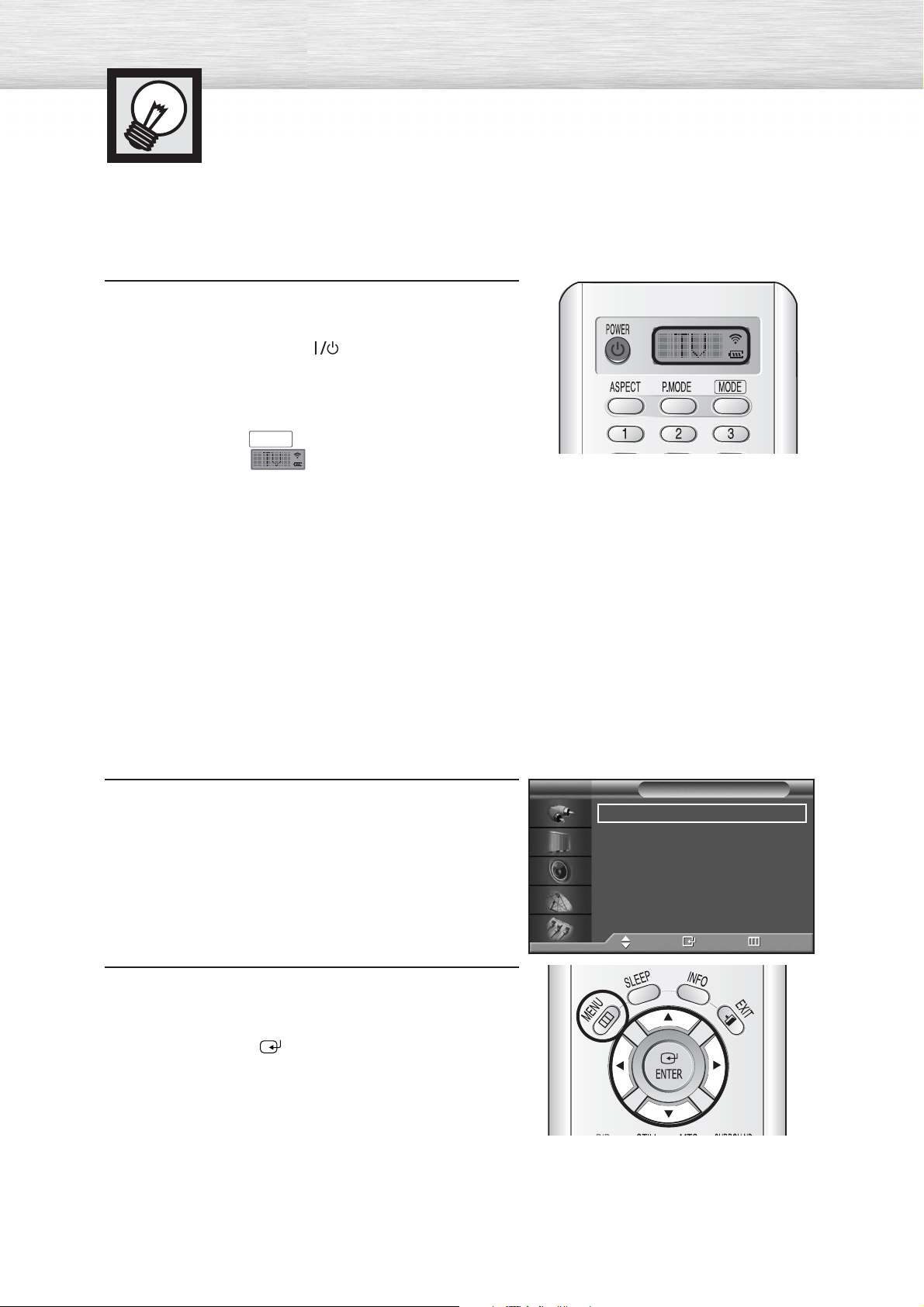
Press the POWER button on the remote control.
The PDP will be turned on and you will be ready to use its
features.
You can also use the POWER ( )button on the front of the
PDP.
Notes:
• If your PDP isn’t turned on when the power button is
pressed: Press the
has been chosen ( ).
MODE
button to check if the TV mode
Viewing the Menus and Displays
Your PDP has a simple, easy-to-use menu system that appears on the PDP screen. This system makes it
convenient and fast to use features on the PDP. Your PDP also lets you display the status of many of your
PDP’s features.
Viewing the Menus
With the power on, press the MENU button on the
remote control. The main menu appears on the screen.
1
The Input menu is selected.
Press the ▲ or ▼ buttons to move to items in the menu.
Press the œ/√/ENTER buttons to display, change, or
2
use the selected items.
Press the ENTER ( ) button to enter items in the menu.
On screen menus disappear from the screen
automatically after about two minutes, or you can
press the MENU or EXIT button on your remote control
to exit the menu.
TV
Source List : TV √
Edit Name √
Move Enter Return
Input
26
Page 27
Displaying Status Information
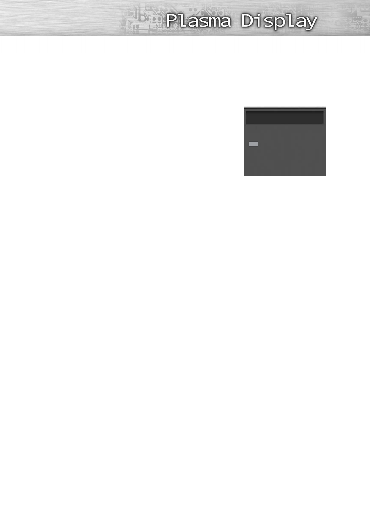
Press the INFO button on the remote control.
The PDP will display the Picture mode, Sound mode, MTS,
Caption, and Clock.
Air 4
Mono
V-Chip
CC
Picture : Custom
Sound : Custom
MTS : Stereo
Clock : 12 : 00 am
27
Page 28

Plug & Play Feature
When the television is initially powered ON, several basic customer settings proceed
automatically and subsequently. The following settings are available.
If the television is in Standby mode, press the
POWER button on the remote control.
1
The message Start Plug & Play is displayed and then the Language
➤
➤
menu is automatically displayed.
Select the appropriate language by pressing the
▲ or ▼ button.
2
The message Check antenna input is displayed.
➤
➤
Press the ENTER button to confirm your choice.
3
Plug & Play
Start Plug & Play
Start
Enter Exit
Language
English
Français
Español
Move Enter Skip
Plug & Play
Check antenna input.
Press the ENTER button.
4
Enter Skip
28
Page 29

Select the correct signal source (Air, STD, HRC and
IRC) by pressing the ▲ or ▼ button, then press the
5
ENTER button.
To start the channel search, press the ENTER button.
The search will end automatically. Channels are sorted and stored in
➤
➤
6
an order which reflects their position in the frequency range (with
lowest first and highest last).
When it has finished, the Clock Set menu is displayed.
Air/CATV
Air
STD
HRC
IRC
Move Enter Skip
Auto Program
Start
To stop the search before it has finished or return to normal
➤
➤
viewing, press the MENU button.
Press the ENTER button.
Press the œ or √ button to move to the Hour, Minute,
7
or am/pm.
Set the Hour, Minute, or am/pm by pressing the
▲ or ▼ button.
Press the ENTER button.
Enter Skip
Auto Program
Stop
Enter Skip
Clock
Hour Minute am/pm
12 00
Move Adjust
Air 10
am
Skip
When it has finished, the message “Enjoy your
watching” is displayed, and the channels which
8
have been stored can be viewed.
Enjoy your watching.
29
Page 30
Plug & Play Feature (continued)
If you want to reset this feature...
Press the MENU button. Press the ▲ or ▼ button to
select “Setup”, then press the ENTER button.
1
Press the ▲ or ▼ button to select “Miscellaneous”,
then press the ENTER button.
2
Press the ▲ or ▼ button to select “Plug & Play”.
Press the ENTER button.
3
TV
TV
Setup
Language : English
Time
Caption
Digital NR : On
V-Chip
Miscellaneous
PC
Color Weakness : Off
Move Enter Return
Miscellaneous
Melody : On
Plug & Play
Blue Screen : Off
Fan : On
Move Enter Return
Plug & Play
Start Plug & Play.
√
√
√
√
√
√
√
√
√
√
√
√
For further details on how to set, refer to the
previous page.
4
Note
• Plug and Play can only be accessed in the TV mode.
Start
ReturnEnter
30
Page 31

Memorizing the Channels
Your PDP can memorize and store all of the available channels for both “off-air”
(antenna) and cable channels. After the available channels are memorized, use the
CH and CH buttons to scan through the channels. This eliminates the need to
change channels by entering the channel digits. There are three steps for memorizing
channels: selecting a broadcast source, memorizing the channels (automatic) and
adding and deleting channels (manual).
Selecting the Video Signal-source
Before your television can begin memorizing the available channels, you must specify the type of signal
source that is connected to the PDP (i.e., an antenna or a cable system).
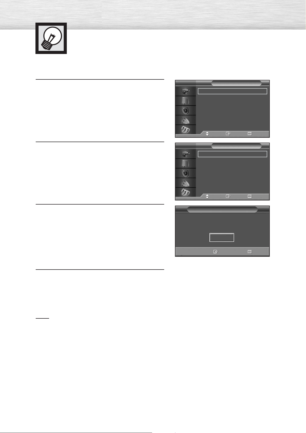
Press the MENU button. Press the ▲ or ▼ button to
select “Channel”, then press the ENTER button.
1
Press the ENTER button to select “Air/CATV”.
2
Press the ▲ or ▼ button to select “Air”, “STD”,
“HRC” or “IRC”, then press the ENTER button.
3
• If you are connected to an antenna, leave “Air”
displayed. If you connected cable, press the
▲ or ▼ button to the display the type of cable
system: “STD”, “HRC” or “IRC”.
(If you are not sure which type of cable system you
have, contact your cable company).
TV
TV
TV
Channel
Air/CATV : Air
Auto Program
Add/Delete
Fine Tune
LNA : On
Scan
Move Enter Return
Channel
Air/CATV : Air
Auto Program
Add/Delete
Fine Tune
LNA : On
Scan
Move Enter Return
Channel
Air/CATV : Air
Auto Program
Add/Delete
Fine Tune
LNA : On
Scan
Move Enter Return
√
√
√
√
√
√
Air
STD
HRC
IRC
Air
STD
HRC
IRC
Press the MENU button to exit.
4
Note
• STD, HRC and IRC identify various types of cable TV systems. Contact your local cable company to
identify the type of cable system that exists in your particular area. At this point the signal source
has been selected. Proceed to “Storing Channels in Memory” (Next page).
31
Page 32

Storing Channels in Memory (Automatic Method)
First, select the correct signal source (Air, STD, HRC
and IRC). See steps on previous page.
1
Press the MENU button. Press the ▲or ▼button to
select “Channel”, then press the ENTER button.
Press the ▲ or ▼ button to select “Auto Program”,
then press the ENTER button.
2
Quick way to access the Automatic Channel Setting: Just press the
➤
➤
“AUTO PROG.” button on the remote control.
Press the ENTER button.
The PDP will begin memorizing all of the available
3
channels.
After all the available channels are stored, the Auto
pro gram menu reappears.
Press the ENTER button to stop.
TV
TV
Channel
Air/CATV : Air
Auto Program
Add/Delete
Fine Tune
LNA : On
Scan
Move Enter Return
Channel
Air/CATV : Air
Auto Program
Add/Delete
Fine Tune
LNA : On
Scan
Move Enter Return
Auto Program
Start
√
√
√
√
√
√
√
√
√
√
√
√
Enter Return
Press the MENU button to exit.
4
Note
• The PDP automatically cycles through all of the available channels and stores them in memory.
This takes about one to two minutes.
32
Page 33

Adding and Erasing Channels (Manual Method)
First, press the CH or CH button or the number buttons
to select the channel you want to add or delete.
Press the MENU button. Press the ▲or ▼button to
select “Channel”, then press the ENTER button.
1
Quick way to access the Adding and Erasing Channels :
➤
➤
Just press the “ADD/DEL” button on the remote control.
Press the ▲or ▼button to select “Add/Delete”,
then press the ENTER button.
2
Repeatedly pressing ENTER button will alternate
between “Add” and “Delete”.
Press the CH or CH button to change
channels you want to add or delete.
Press the MENU button to exit.
3
TV
Air/CATV : Air
Auto Program
Add/Delete
Fine Tune
LNA : On
Scan
TV
Air/CATV : Air
Auto Program
Add/Delete
Fine Tune
LNA : On
Scan
Air 4 Deleted
Channel
√
√
√
√
√
√
Move Enter Return
Channel
√
√
√
√
√
√
Move Enter Return
Add/Delete
Add
Change
Enter Return
Note
•You can view any channel (including an erased channel) by using the number buttons on the
remote control.
33
Page 34

To View Memorized Channels (PIP Mode)
Press the MENU button. Press the ▲ or ▼ button to
select “Channel”, then press the ENTER button.
1
Press the ▲ or ▼ button to select “Scan”, then press
the ENTER button.
2
Only the memorized channels are chosen.
When Channel scan starts, PIP mode will be activated automatically.
➤
➤
The screen will remain in PIP mode when the SCAN has finished.
Press the PIP button to exit PIP mode.
Press the MENU button to stop.
3
TV
Channel
Air/CATV : Air
Auto Program
Add/Delete
Fine Tune
LNA : On
Scan
Move Enter Return
Scan
Air 4
√
√
√
√
√
√
Return
34
Page 35

35
Changing Channels
Using the Channel Buttons
Press the CH or CH button to change channels.
When you press the CH or CH button, the PDP changes channels
in sequence. You will see all the channels that the PDP has memorized.
(The PDP must have memorized at least three channels.)
You will not see channels that were either erased or not memorized.
Directly Accessing Channels
Press the number buttons to go directly to a channel. For example, to select
channel 27, press “2” then “7”. The TV will change channels when you
press the second number.
When you use the number buttons, you can directly select channels that were
either erased or not memorized. To change to single-digit channels (0~9) faster,
press “0” before the single digit. (For channel “4” press “0”, then “4”).
Using the PRE-CH button to select the previous channel
Press the PRE-CH button. The TV will switch to the last channel viewed.
To quickly switch between two channels that are far apart, tune to one
channel, then use the number button to select the second channel. Then,
use the PRE-CH button to quickly alternate between them.
Adjusting the Volume
Using the Volume Buttons
Press the VOL + or VOL – button to increase or decrease the volume.
Using Mute
Using the MUTE Buttons
At any time, you can temporarily cut off the sound using the MUTE button.
1
Press the MUTE button and the sound cuts off.
The word “Mute” will appear in the lower-left
corner of the screen.
2
To turn mute off, press the MUTE button again, or
simply press the VOL + or VOL – button.
Mute
Page 36

Setting Up Your Remote Control
This PDP's remote control can operate almost any VCR, cable box or DVD. After it has been set up
properly, your remote control can operate in four different modes :TV , VCR, Cable, DVD or STB.
Pressing the corresponding button on the remote control allows you to switch between these modes,
and control whichever piece of equipment you choose.
Note :●The remote control may not be compatible with all DVD Players, VCRs, Cable boxes.
●
The remote control can only operate STB made by Samsung.
Setting Up the Remote to Operate Your VCR, Cable box or DVD player
Turn off your VCR. (or Cable box, DVD player)
1
Press the MODE button. The Mode is changed
whenever MODE button is pressed.
2
Press the SET button on your TV's remote control.
3
Using the number buttons on your remote control,
enter three digits of the VCR (or Cable box, DVD
4
player) code listed on page 37 of this manual for
your brand of VCR (or CATV, DVD). Make sure you
enter three digits of the code, even if the first digit
is a "0".
(If more than one code is listed, try the first one.)
Press the POWER button on the remote control.
Your VCR (or CATV, DVD) should turn on if your
5
remote is set up correctly. If your VCR (or CATV,
DVD) does not turn on after setup, repeat steps
2, 3, and 4, but try one of the other codes listed for
your brand of VCR (or CATV, DVD).
If no other codes are listed, try each code, 000
through 089 (or Cable box: 000 through 077,
DVD player: 000 through 008).
Notes
• When your remote control is in “VCR” mode, the VCR control buttons (STOP, REW, PLAY/PAUSE, FF)
still operate your VCR.
• When your remote control is in “CATV” or “DVD” mode, the VCR control buttons (STOP, REW,
PLAY/PAUSE, FF) still operate your VCR.
•You do not need to program the remote for Samsung STBs as the codes are pre-programmed.
36
Page 37

Remote Control Codes
VCR Codes
Cable Box Codes
DVD Codes
37
Page 38

Viewing an External Signal Source
Use the remote control to switch between viewing signals from connected equipment,
such as VCRs, DVD, Set-Top box and the TV source (broadcast or cable).
Setting the Signal Source
Press the MENU button. Press the ENTER button to
select “Input”.
1
Quick way to access viewing an external signal source :
➤
➤
Just press the “SOURCE” button on the remote control.
Press the ENTER button to select “Source List”.
2
Press the ▲ or ▼ button to select signal source, then
press the ENTER button.
3
Press the MENU button to exit.
4
TV
TV
TV
Input
Source List : TV √
Edit Name √
Move Enter Return
Source List
TV
AV1
AV2
S-Video
Component1
Component2
PC
DVI
Move Enter Return
TV
AV1 VCR
AV2
S-Video
Component1
Component2
PC
DVI
Move Enter Return
- - - -
- - - -
- - - -
- - - -
- - - -
- - - -
- - - -
Source List
- - - -
- - - -
- - - -
- - - -
- - - -
- - - -
Notes
• When you connect equipment to the PDP, you can choose between the following sets of jacks:
AV1, AV2, S-Video, Component1, Component2, PC or DVI on the PDP’s rear panel.
38
Page 39

Assigning Names to External input mode
Press the MENU button. Press the ENTER button to
select “Input”.
1
Press the ▲ or ▼ button to select “Edit Name”, then
press the ENTER button.
2
Press the ENTER button.
Press the ▲ or ▼ button to select external device,
3
then press the ENTER button.
• You can select the VCR, DVD, Cable STB, HD
STB, Satellite STB, AV Receiver, DVD Receiver,
Game, Camcorder, DVD Combo, DHR or PC.
• Set other signal sources (AV2, S-Video,
Component1, Component2, PC or DVI) using
the same method as listed above.
TV
Source List : TV √
Edit Name √
Move Enter Return
TV
AV1 :
AV2 :
S-Video :
Component1 :
Component2 :
PC :
DVI :
Move Enter Return
TV
AV1 :
AV2 :
S-Video :
Component1 :
Component2 :
PC :
DVI :
Move Enter Return
Edit Name
Edit Name
Input
Edit Name
- - - -
- - - -
- - - -
- - - -
- - - -
- - - -
- - - -
Edit Name
- - - -
- - - -
- - - -
VCR
- - - -
DVD
- - - -
Cable STB
HD STB
- - - -
Satellite STB
√
√
√
√
√
√
√
√
√
√
√
√
†
Press the MENU button to exit.
4
Notes
• DHR : DVD HDD Recorder
39
Page 40

Page 41

PLASMA DISPLAY PANEL
Picture Control
Customizing the Picture ................................................................42
Using Automatic Picture Settings ....................................................43
Selecting the Color Tone................................................................44
DNIe (Digital Natural Image engine) ............................................45
Changing the Screen Size ............................................................46
Freezing the Picture ......................................................................48
Viewing the Picture-in-Picture..........................................................49
Selecting a Signal Source (Antenna or Cable) for PIP........................54
Setting the MCC(My Control Color) Mode ......................................56
Page 42

Customizing the Picture
You can use the on-screen menus to change the Contrast, Brightness, Sharpness, Color,
and Tint settings of your PDP.
Press the MENU button. Press the ▲ or ▼ button to
select “Picture”, then press the ENTER button.
1
Press the ▲ or ▼ button to select “Custom”, then
press the ENTER button.
2
You will also see the items “Contrast”, “Brightness”,
“Sharpness”, “Color” and “Tint”.
Press the ▲ or ▼ button to select the item you wish
to change, then press the ENTER button.
3
Press the œ or √ button to change the value of the
item.
TV
Mode : Custom √
Custom √
Color Tone : Normal √
Color Control √
Film Mode : Off √
Size : 16:9 √
PIP √
† More
Move Enter Return
TV
Contrast 80
Brightness 50
Sharpness 50
Color 50
Tint G 50 R 50
Move Enter Return
Contrast 74
Picture
Custom
Press the MENU button to exit.
4
Note
• In the PC/DVI mode, you can’t adjust the Color and Tint.
42
Page 43

Using Automatic Picture Settings
Your PDP has automatic picture settings that allow you to adjust the video display easily.
Press the MENU button. Press the ▲ or ▼ button to
select “Picture”, then press the ENTER button.
1
Quick way to access the picture setting: Just press the “P.MODE”
➤
➤
button on the remote control.
Press the ENTER button to select “Mode”.
2
Press the ▲ or ▼ button to select “Dynamic”,
“Standard”, “Movie”, “Custom” picture setting, then
3
press the ENTER button.
• You can select “Custom”, “Entertain”, “Internet”,
or “Text” in PC/DVI mode.
TV
Mode : Custom √
Custom √
Color Tone : Normal √
Color Control √
Film Mode : Off √
Size : 16:9 √
PIP √
† More
Move Enter Return
TV
Mode : Custom
Custom
Color Tone : Normal
Color Control
Film Mode : Off
Size : 16:9
PIP
† More
Move Enter Return
TV
Mode : Custom
Custom
Color Tone : Normal
Color Control
Film Mode : Off
Size : 16:9
PIP
† More
Move Enter Return
Picture
Picture
Dynamic
Standard
Movie
Custom
Picture
Dynamic
Standard
Movie
Custom
Press the MENU button to exit.
4
• Choose Dynamic for viewing the TV during the day or
when there is bright light in the room.
•Choose Standard for the standard factory settings.
• Choose Movie when viewing the movie.
• Choose Custom if you want to adjust the settings
according to personal
preference (see “Customizing the Picture”, page 42).
43
Page 44

Selecting the Color Tone
Press the MENU button. Press the ▲ or ▼ button to
select “Picture”, then press the ENTER button.
1
Press the ▲ or ▼ button to select “Color Tone”, then
press the ENTER button.
2
Press the ▲ or ▼ button to select “Cool2”, “Cool1”,
“Normal”, “Warm1” or “Warm2”, then press the
3
ENTER button.
•You can select “Custom”, “Cool”, Normal” or
“Warm” in PC mode.
•You can select “Cool”, “Normal” or “Warm”
in DVI mode.
TV
TV
TV
Picture
Mode : Custom √
Custom √
Color Tone : Normal √
Color Control √
Film Mode : Off √
Size : 16:9 √
PIP √
† More
Move Enter Return
Picture
Mode : Custom
Custom
Color Tone : Normal
Color Control
Film Mode : Off
Size : 16:9
PIP
† More
Move Enter Return
Mode : Custom
Custom
Color Tone : Normal
Color Control
Film Mode : Off
Size : 16:9
PIP
† More
Move Enter Return
Cool2
Cool1
Normal
Warm1
Warm2
Picture
Cool2
Cool1
Normal
Warm1
Warm2
44
Press the MENU button to exit.
4
Page 45

DNIe (Digital Natural Image engine)
Samsung’s New Technology brings you more detailed images with contrast,
white enhancement and 3D noise reduction.
Press the MENU button. Press the ▲ or ▼ button to
select “Picture”, then press the ENTER button.
1
Quick way to select DNIe: Simply press the “DNIe” button under
➤
➤
the cover of the remote control.
Press the ▲ or ▼ button to select “DNIe”, then press
the ENTER button.
2
Press the ▲ or ▼ button to select “On”, “Off” or
“Demo”, then press the ENTER button.
3
•On : Switches on the DNIe mode.
•Off : Switches off the DNIe mode.
•Demo : The screen before applying DNIe appears
on the right and the screen after applying
DNIe appears on the left.
TV
Mode : Custom √
Custom √
Color Tone : Normal √
Color Control √
Film Mode : Off √
Size : 16:9 √
PIP √
† More
Move Enter Return
TV
… More
DNIe : On
MCC :
Move Enter Return
TV
… More
DNIe : On
MCC :
Move Enter Return
Picture
Picture
On
Off
Demo
Picture
On
Off
Demo
Press the MENU button to exit.
4
45
Page 46

Changing the Screen Size
Screen size selection depends on the type of video input(DVD, PC etc.).
Press the MENU button. Press the ▲ or ▼ button to
select “Picture”, then press the ENTER button.
1
Quick way to access the Screen Size menu : Just press the
➤
➤
“ASPECT” button on the remote control.
Press the ▲ or ▼ button to select “Size”, then press
the ENTER button.
2
Press the ▲ or ▼ button to select the screen size you
want, then press the ENTER button.
3
TV
TV
TV
Picture
Mode : Custom √
Custom √
Color Tone : Normal √
Color Control √
Film Mode : Off √
Size : 16:9 √
PIP √
† More
Move Enter Return
Picture
Mode : Custom √
Custom √
Color Tone : Normal √
Color Control √
Film Mode : Off √
Size : 16:9 √
PIP √
† More
Move Enter Return
Size
16 : 9
Panorama
Zoom
4 : 3
Move Enter Return
Press the MENU button to exit.
4
Note
• If you watch a still image or the 4:3 (Normal) mode for a long time (over 2 hours), an image may
be burned onto the screen.
View the monitor in 16:9(Wide) or Panorama mode as much as possible.
46
Page 47

16:9(W
16:9(W
16:9 Aspect Ratio that fits DVD and Wide Screen
applications.
Panorama
Panorama
Fits a 16:9 picture onto a 4:3 screen and displays
it without clipping the image.
Zoom
Zoom
Magnifies the 16:9 wide picture (in a vertical
direction) to fit the screen size.
Select by pressing the œ or √ button.
Use the ▲ or ▼ button to move the picture up and
down. After selecting , use the ▲ or ▼ button
to magnify or reduce the picture size in a vertical
direction.
ide)
ide)
16:9
Panorama
Zoom
4 : 3(Nor
4 : 3(Nor
Standard TV and VCR screen size having a 4:3
Aspect Ratio.
mal)
mal)
4:3
Notes
• In TV, VIDEO, S-VIDEO and Component (480i) modes, all screen modes can be selected.
(16:9 ➞Panorama ➞Zoom ➞4:3).
• In PC/DVI mode, only 16:9 & 4:3 modes can be selected.
• In Component (480p, 720p. 1080i) modes, Panorama mode can’t be selected.
• In Component (480p, 720p. 1080i) modes, you can move the picture on screen by pressing
the ▲ or ▼ button. (All screen modes)
• Changing the screen size to Normal, or Zoom during PIP mode will cause the PIP window to
disappear.
47
Page 48

Freezing the Picture
Still
Press the STILL button on the remote control to freeze a
moving picture. Press again to cancel.
48
Page 49

Viewing the Picture-in-Picture
Selecting the PIP Screen
Press the MENU button. Press the ▲ or ▼ button to
select “Picture”, then press the ENTER button.
1
Quick way to access the PIP mode: Just press the “PIP” button on
➤
➤
the remote control.
For further information on “Sound Select”, refer to page 67.
➤
➤
Press the ▲ or ▼ button to select “PIP”, then
press the ENTER button.
2
Press the ENTER button, then press the ▲ or ▼
button to select “On”. The PIP image will appear in
3
the corner of the screen.
•Pressing the ▲ or ▼ button will alternate between
“On” and “Off”.
Note
• Check if the V-Chip Lock (refer to page 101) is
ON if the PIP On/Off will not function. PIP does
not function when the V-Chip Lock is set to On.
Change the setting to Off and try it again.
TV
Mode : Custom √
Custom √
Color Tone : Normal √
Color Control √
Film Mode : Off √
Size : 16:9 √
PIP √
† More
Move Enter Return
TV
PIP : Off √
Source : TV √
Swap √
Size : √
Position : √
Air/CATV : Air √
Channel : 4 √
Sound Select : Main √
Move Enter Return
TV
PIP : Off
Source : TV
Swap
Size :
Position :
Air/CATV : Air
Channel : 4
Sound Select : Main
Move Enter Return
Picture
PIP
PIP
Off
On
Press the MENU button to exit.
4
PIP Settings
Main screen
PIP screen
TV
AV 1
AV 2
S-Video
Component 1
Component 2
PC
DVI
TV AV 1 AV 2 S-Video
O
O
O
O
O
O
O
O
O:
PIP and Swap Operate
X:
PIP doesn’t Operate
Component 2Component 1
O
X
O
O
O
O
O
O
O
O
X
O
O
O
O
O
O
O
O
X
O
O
O
O
O
O
O
O
X
X
X
X
O
O
O
O
X
X
X
X
PC
O
O
O
O
X
X
X
X
DVI
O
O
O
O
X
X
X
X
49
Page 50

Selecting an External Signal
You can use PIP to view a signal from an external source, such as a VCR.
Press the MENU button. Press the ▲ or ▼ button to
select “Picture”, then press the ENTER button.
1
Press the ▲ or ▼ button to select “PIP”, then press
the ENTER button.
2
Press the ▲ or ▼ button to select “Source”, then
press the ENTER button.
3
TV
TV
TV
Picture
Mode : Custom √
Custom √
Color Tone : Normal √
Color Control √
Film Mode : Off √
Size : 16:9 √
PIP √
† More
Move Enter Return
PIP
PIP : On √
Source : TV √
Swap √
Size : √
Position : √
Air/CATV : Air √
Channel : 4 √
Sound Select : Main √
Move Enter Return
PIP
PIP : Off
Source : TV
Swap
Size :
Position :
Air/CATV : Air
Channel : 22
Sound Select : Main
Move Enter Return
TV
AV1
AV2
S-Video
Component1
Component2
†
Press the ▲ or ▼ button to cycle through all of the
available signal sources:
4
“TV”, “AV1”, “AV2”, “S-Video”, “Component1”,
“Component2”, “PC” and “DVI”.
The signal from these inputs will not appear if you
have not connected any equipment to the PDP's
respective input jacks.
Press the MENU button to exit.
TV
PIP : Off
Source : TV
Swap
Size :
Position :
Air/CATV : Air
Channel : 4
Sound Select : Main
Move Enter Return
5
Note
• The PIP function operates in Wide screen.
• Using Multi-Screen in the Normal (4:3) or Zoom screen will change the size of the main screen to
Wide screen.
50
PIP
…
PC
DVI
Page 51

Swapping the Contents of the PIP and Main Image
Press the MENU button. Press the ▲ or ▼ button to
select “Picture”, then press the ENTER button.
1
Quick way to access swapping: Just press the “SWAP” button under
➤
➤
the cover of the remote control.
Press the ▲ or ▼ button to select “PIP”, then press
the ENTER button.
2
Press the ▲ or ▼ button to select “Swap”, then
press the ENTER button.
3
• The image in the PIP window will appear on the
main screen, and vice versa.
TV
Mode : Custom √
Custom √
Color Tone : Normal √
Color Control √
Film Mode : Off √
Size : 16:9 √
PIP √
† More
Move Enter Return
TV
PIP : On √
Source : TV √
Swap √
Size : √
Position : √
Air/CATV : Air √
Channel : 4 √
Sound Select : Main √
Move Enter Return
TV
PIP : On √
Source : TV √
Swap √
Size : √
Position : √
Air/CATV : Air √
Channel : 4 √
Sound Select : Main √
Move Enter Return
Picture
PIP
PIP
Press the MENU button to exit.
4
51
Page 52

Changing the Size of the PIP Window
Press the MENU button. Press the ▲ or ▼ button to
select “Picture”, then press the ENTER button.
1
Quick way to access PIP size: Just press the “SIZE” button under
➤
➤
the cover of the remote control.
Press the ▲ or ▼ button to select “PIP”, then press
the ENTER button.
2
Press the ▲ or ▼ button to select “Size”, then press
the ENTER button.
3
TV
TV
TV
Picture
Mode : Custom √
Custom √
Color Tone : Normal √
Color Control √
Film Mode : Off √
Size : 16:9 √
PIP √
† More
Move Enter Return
PIP
PIP : On √
Source : TV √
Swap √
Size : √
Position : √
Air/CATV : Air √
Channel : 4 √
Sound Select : Main √
Move Enter Return
PIP
PIP : On
Source : TV
Swap
Size :
Position :
Air/CATV : Air
Channel : 4
Sound Select : Main
Move Enter Return
52
Press the ▲ or ▼ button to select option you want,
then press the ENTER button.
4
Press the MENU button to exit.
5
TV
PIP
PIP : On
Source : TV
Swap
Size :
Position :
Air/CATV : Air
Channel : 4
Sound Select : Main
Move Enter Return
Page 53

Changing the Location of the PIP Image
Press the MENU button. Press the ▲ or ▼ button to
select “Picture”, then press the ENTER button.
1
Press the ▲ or ▼ button to select “PIP”, then press
the ENTER button.
2
Press the ▲ or ▼ button to select “Position”, then
press the ENTER button.
3
TV
Mode : Custom √
Custom √
Color Tone : Normal √
Color Control √
Film Mode : Off √
Size : 16:9 √
PIP √
† More
Move Enter Return
TV
PIP : On √
Source : TV √
Swap √
Size : √
Position : √
Air/CATV : Air √
Channel : 4 √
Sound Select : Main √
Move Enter Return
TV
PIP : On
Source : TV
Swap
Size :
Position :
Air/CATV : Air
Channel : 4
Sound Select : Main
Move Enter Return
Picture
PIP
PIP
Press the ▲ or ▼ button to select the PIP position
you want, then press the ENTER button.
4
Press the MENU button to exit.
TV
PIP : On
Source : TV
Swap
Size :
Position :
Air/CATV : Air
Channel : 4
Sound Select : Main
5
Note
• The Double 1( ) or Double 2 ( ) mode can not be selected in position.
PIP
Move Enter Return
53
Page 54

Selecting a Signal Source (Antenna or Cable) for PIP
If the PIP source is TV while PIP is ON, you can select a different broadcasting source
for the PIP picture from the main picture.
Press the MENU button. Press the ▲ or ▼ button to
select “Picture”, then press the ENTER button.
1
Press the ▲ or ▼ button to select “PIP”, then press
the ENTER button.
2
Press the
press the ENTER button.
3
▲ or ▼
button to select “Air/CATV”, then
TV
TV
TV
Picture
Mode : Custom √
Custom √
Color Tone : Normal √
Color Control √
Film Mode : Off √
Size : 16:9 √
PIP √
† More
Move Enter Return
PIP
PIP : On √
Source : TV √
Swap √
Size : √
Position : √
Air/CATV : Air √
Channel : 4 √
Sound Select : Main √
Move Enter Return
PIP
PIP : On
Source : TV
Swap
Size :
Position :
Air/CATV : Air
Channel : 4
Sound Select : Main
Move Enter Return
Air
STD
HRC
IRC
54
If an antenna is connected, the setting is “Air”. If a
Cable TV system is providing the signal, press the
4
▲ or ▼ button until the appropriate type of cable
system is selected (“STD”, “HRC” or “IRC”).
Press the MENU button to exit the menu.
5
TV
PIP
PIP : On
Source : TV
Swap
Size :
Position :
Air/CATV : Air
Channel : 4
Sound Select : Main
Move Enter Return
Air
STD
HRC
IRC
Page 55

Changing the PIP Channel
Press the MENU button. Press the ▲ or ▼ button to
select “Picture”, then press the ENTER button.
1
Quick way to change the PIP channel: Just press the “CH “ or
➤
➤
“CH ” button under the cover of the remote control.
Press the ▲ or ▼ button to select “PIP”, then press
the ENTER button.
2
Press the ▲ or ▼ button to select “Channel”, then
press the ENTER button.
3
TV
Mode : Custom √
Custom √
Color Tone : Normal √
Color Control √
Film Mode : Off √
Size : 16:9 √
PIP √
† More
Move Enter Return
TV
PIP : On √
Source : TV √
Swap √
Size : √
Position : √
Air/CATV : Air √
Channel : 4 √
Sound Select : Main √
Move Enter Return
TV
PIP : On
Source : TV
Swap
Size :
Position :
Air/CATV : Air
Channel : 4
Sound Select : Main
Move Enter Return
Picture
PIP
PIP
▲
4
▲
Press the ▲ or ▼ button to change the channel that
appears in the PIP window.
4
Press the MENU button to exit.
5
TV
PIP : On
Source : TV
Swap
Size :
Position :
Air/CATV : Air
Channel : 4
Sound Select : Main
Move Enter Return
PIP
11
▲
▲
5555
Page 56

Setting the MCC(My Control Color) Mode
MCC (My Color Control) Modes:
MCC allows users to adjust colors to according to their preferences, by adjusting skin, sky,
and grass tones using the predefined settings (Standard, Custom, Turkish Blue, Emerald Green,
Indian Pink) without affecting other colors on the screen.
Using the MCC Function in the Easy Control Menu
Skin, sky and grass tones are easily adjustable to suit your preferences.
Press the MENU button. Press the ▲ or ▼ button to
select “Picture”, then press the ENTER button.
1
Press the ▲ or ▼ button to select “MCC”, then press
the ENTER button.
2
Press the
then press the ENTER button.
3
▲ or ▼
button to select “Easy Control”,
TV
Mode : Custom √
Custom √
Color Tone : Normal √
Color Control √
Film Mode : Off √
Size : 16:9 √
PIP √
† More
Move Enter Return
TV
Easy Control : Custom √
Detail Control : √
Move Enter Return
Original Turkish Blue
Picture
MCC
56
Press
the œ or √ button to select among the various
picture settings. The original picture (before
4
adjustment) is shown on the left side, while the
selected mode is shown on the right side.
There are five MCC modes: Standard, Custom, Turkish Blue,
➤
➤
Emerald Green and Indian Pink.
Press the MENU button to exit the menu.
5
Easy Control
Turkish Blue Emerald Green Indian Pink
Move Enter Return
Original Turkish Blue
Easy Control
Turkish Blue Emerald Green Indian Pink
Move Enter Return
√
√
Page 57

MCC Mode Characteristics
Using MCC Mode, you can enjoy vivid colors as shown below.
Original Turkish Blue
Standard Picture.
➤
➤
Emerald Green Indian Pink
Emphasizes Mild Greens.
➤
➤
Emphasizes Clear Blues.
➤
➤
Emphasizes Warm Skin Colors.
➤
➤
Note
•Images shown above may differ from the actual adjustment on the screen.
These images are presented for illustrative purposes.
5757
Page 58

Setting the MCC(My Control Color) Mode
MCC Custom Settings
Users can adjust the 3 MCC colors (Skin, Sky, and Grass Tones).
Press the MENU button. Press the ▲ or ▼ button to
select “Picture”, then press the ENTER button.
1
Press the ▲ or ▼ button to select “MCC”, then press
the ENTER button.
2
Press the
then press the ENTER button.
3
▲ or ▼
button to select “Detail Control”,
TV
TV
TV
Picture
Mode : Custom √
Custom √
Color Tone : Normal √
Color Control √
Film Mode : Off √
Size : 16:9 √
PIP √
† More
Move Enter Return
MCC
Easy Control : Custom √
Detail Control : √
Move Enter Return
Detail Control
Skin Tone 50
Green Grass 50
Blue Sky 50
Reset
58
Press
the ▲ or ▼ button to select the desired MCC
color and
4
➤
➤
Press the
Press the
5
colors.
Press the ENTER or MENU button to confirm the
changes and return to the previous menu.
6
then press the ENTER or √ button.
The original picture (before adjustment) is shown on the left side,
while the picture after adjustment is shown on the right side, and
an adjustment bar on the bottom of the screen.
œ or √
▲ or ▼
button to adjust the settings.
button to choose other MCC
Move Enter Return
Original Turkish Blue
Original Turkish Blue
Detail Control
Skin Tone
Move Adjust Return
50
Page 59

Resetting the MCC Colors to the Factory Defaults
To return to the factory default settings for MCC colors, use the Reset function.
Press the MENU button. Press the ▲ or ▼ button to
select “Picture”, then press the ENTER button.
1
Press the ▲ or ▼ button to select “MCC”, then press
the ENTER button.
2
Press the
then press the ENTER button.
3
▲ or ▼
button to select “Detail Control”,
TV
TV
TV
Picture
Mode : Custom √
Custom √
Color Tone : Normal √
Color Control √
Film Mode : Off √
Size : 16:9 √
PIP √
† More
Move Enter Return
MCC
Easy Control : Custom √
Detail Control : √
Move Enter Return
Detail Control
Skin Tone 60
Green Grass 35
Blue Sky 80
Reset
Press the
press the ENTER button.
4
The previously adjusted MCC Colors will be reset to
the factory defaults.(The default value for MCC
5
colors is 50.)
▲ or ▼
button to select “Reset” and
TV
Move Enter Return
Detail Control
Skin Tone 50
Green Grass 50
Blue Sky 50
Reset
Move Enter Return
5959
Page 60

Page 61

PLASMA DISPLAY PANEL
Sound Control
Customizing the Sound ................................................................62
Using Automatic Sound Settings ....................................................63
Choosing a Multi-Channel Sound (MTS)Soundtrack ..........................64
Using the Auto Volume ..................................................................65
Setting the TruSurround XT ............................................................66
Listening to the Sound of the Sub(PIP) Picture....................................67
Selecting the Internal Mute ............................................................68
Page 62

Customizing the Sound
Press the MENU button. Press the ▲ or ▼ button to
select “Sound”, then press the ENTER button.
1
Press the ▲ or ▼ button to select “Custom”, then
press the ENTER button.
2
Select the option (volume, balance, equalizer) to
be adjusted by pressing the œ or √ button.
3
Press the ▲ or ▼ button to adjust the setting.
TV
TV
Sound
Mode : Custom √
Custom √
MTS : Stereo √
Auto Volume : Off √
SRS TSXT : Stereo √
Internal Mute : Off √
Move Enter Return
Custom
0
R
L
100 300 1K 3K 10K
Adjust Move Return
Press the MENU button to exit.
4
If you make any changes to the equalizer settings, the sound Mode
➤
➤
is automatically switched to the custom mode.
62
Page 63

Using Automatic Sound Settings
Press the MENU button. Press the ▲ or ▼ button to
select “Sound”, then press the ENTER button.
1
Press the ENTER button to select “Mode”.
2
Press the ▲ or ▼ button to select “Standard”,
“Music”, “Movie”, “Speech” or “Custom” sound
3
setting, then press the ENTER button.
TV
Mode : Custom √
Custom √
MTS : Stereo √
Auto Volume : Off √
SRS TSXT : Stereo √
Internal Mute : Off √
Move Enter Return
TV
Mode : Custom
Custom
MTS : Stereo
Auto Volume : Off
SRS TSXT : Stereo
Internal Mute : Off
Move Enter Return
TV
Mode : Custom
Custom
MTS : Stereo
Auto Volume : Off
SRS TSXT : Stereo
Internal Mute : Off
Sound
Sound
Standard
Music
Movie
Speech
Custom
Sound
Standard
Music
Movie
Speech
Custom
Press the MENU button to exit.
4
• Choose Standard for the standard factory settings.
• Choose Music when watching music videos or
concerts.
• Choose Movie when watching movie.
•Choose Speech when watching a show that is mostly
dialogue (i.e., news).
• Choose Custom to recall your personalized settings.
(see “Customizing the Sound”, page 62).
Move Enter Return
63
Page 64

Choosing a Multi-Channel Sound (MTS) Soundtrack
Depending on the particular program being broadcast, you can listen to stereo, mono, or a
Separate Audio Program. (SAP audio is usually a foreign-language translation. Sometimes
SAP has unrelated information like news or weather.)
Press the MENU button. Press the ▲ or ▼ button to
select “Sound”, then press the ENTER button.
1
Quick way to access the MTS menu: Just press the “MTS” button on
➤
➤
the remote control.
Press the ▲ or ▼ button to select “MTS”, then press
the ENTER button.
2
Press the ▲ or ▼ button to select “Mono”, “Stereo”
or “SAP”, then press the ENTER button.
3
TV
TV
TV
Sound
Mode : Custom √
Custom √
MTS : Stereo √
Auto Volume : Off √
SRS TSXT : Stereo √
Internal Mute : Off √
Move Enter Return
Sound
Mode : Custom
Custom
MTS : Stereo
Auto Volume : Off
SRS TSXT : Stereo
Internal Mute : Off
Move Enter Return
Mode : Custom
Custom
MTS : Stereo
Auto Volume : Off
SRS TSXT : Stereo
Internal Mute : Off
Mono
Stereo
SAP
Sound
Mono
Stereo
SAP
Press the MENU button to exit.
4
• Choose
• Choose
stereo signal.
• Choose
Note
• The MTS function operates in TV mode only.
64
Stereo for channels that are broadcasting in stereo.
Stereo
Mono for channels that are broadcasting in mono, or if you are having difficulty receiving a
Mono
SAP to listen to the Separate Audio Program, which is usually a foreign-language translation.
SAP
Move Enter Return
Page 65

Using the Auto Volume
Each broadcasting station has its own signal conditions, which can make it necessary to
adjust the volume every time the channel is changed. “Auto volume” lets you automatically
adjust the volume of the desired channel by lowering the sound output when the modulation signal is high or by raising the sound output when the modulation signal is low.
Press the MENU button. Press the ▲ or ▼ button to
select “Sound”, then press the ENTER button.
1
Press the ▲ or ▼ button to select “Auto Volume”,
then press the ENTER button.
2
Press the ▲ or ▼ button to select “On”, then press
the ENTER button.
3
• Pressing the ▲ or ▼ button will alternate
between “On” and “Off”.
TV
Mode : Custom √
Custom √
MTS : Stereo √
Auto Volume : Off √
SRS TSXT : Stereo √
Internal Mute : Off √
Move Enter Return
TV
Mode : Custom
Custom
MTS : Stereo
Auto Volume : Off
SRS TSXT : Stereo
Internal Mute : Off
Move Enter Return
TV
Mode : Custom
Custom
MTS : Stereo
Auto Volume : Off
SRS TSXT : Stereo
Internal Mute : Off
Sound
Sound
Off
On
Sound
Off
On
Press the MENU button to exit.
4
Move Enter Return
65
Page 66

Setting the TruSurround XT
TruSurround XT is a patented SRS technology that solves the problem of playing 5.1
multichannel content over two speakers. Trusurround delivers a compelling, virtual surround
sound experience through any two-speaker playback system, including internal television
speakers. It is fully compatible with all multichannel formats.
Press the MENU button. Press the ▲ or ▼ button to
select “Sound”, then press the ENTER button.
1
Quick way to access the TruSurround XT menu: Just press the
➤
➤
“SRS TSXT” button on the remote control.
Press the ▲ or ▼ button to select “SRS TSXT”, then
press the ENTER button.
2
Press the ▲ or ▼ button to change the setting (Off,
3D Mono or Stereo), then press the ENTER button.
3
TV
TV
TV
Sound
Mode : Custom √
Custom √
MTS : Stereo √
Auto Volume : Off √
SRS TSXT : Stereo √
Internal Mute : Off √
Move Enter Return
Sound
Mode : Custom
Custom
MTS : Stereo
Auto Volume : Off
SRS TSXT : Stereo
Internal Mute : Off
Move Enter Return
Mode : Custom
Custom
MTS : Stereo
Auto Volume : Off
SRS TSXT : Stereo
Internal Mute : Off
Move Enter Return
Off
3D Mono
Stereo
Sound
Off
3D Mono
Stereo
66
Press the MENU button to exit.
4
TruSurround XT, SRS and ( ) Symbol
➤
➤
are trademarks of SRS Labs, Inc.
TruSurround XT technology is incorporated
under license from SRS Labs, Inc.
Page 67

Listening to the Sound of the Sub(PIP) Picture
When the PIP feature is activated, you can listen to the sound of the sub picture.
Press the MENU button. Press the ▲ or ▼ button to
select “Picture”, then press the ENTER button.
1
Press the ▲ or ▼ button to select “PIP”, then press
the ENTER button.
2
Press the ▲ or ▼ button to select “Sound Select”,
then press the ENTER button.
3
•Pressing the ▲ or ▼ button will alternate between
“Main” and “Sub”.
TV
Mode : Custom √
Custom √
Color Tone : Normal √
Color Control √
Film Mode : Off √
Size : 16:9 √
PIP √
† More
Move Enter Return
TV
PIP : On √
Source : TV √
Swap √
Size : √
Position : √
Air/CATV : Air √
Channel : 4 √
Sound Select : Main √
Move Enter Return
TV
PIP : On
Source : TV
Swap
Size :
Position :
Air/CATV : Air
Channel : 4
Sound Select : Main
Move Enter Return
Picture
PIP
PIP
Main
Sub
Set to Sub by pressing the ▲ or ▼ button.
4
•You can listen to the sound of the sub picture.
To listen the sound of the main picture, set to Main.
➤
➤
TV
PIP : On
Source : TV
Swap
Size :
Position :
Air/CATV : Air
Channel : 4
Sound Select : Main
Move Enter Return
PIP
Off
On
Main
Sub
67
Page 68

Selecting the Internal Mute
The internal speakers can be muted in order to hear sound from external speakers
you've connected.
Press the MENU button. Press the ▲ or ▼ button to
select “Sound”, then press the ENTER button.
1
Press the ▲ or ▼ button to select “Internal Mute”,
then press the ENTER button.
2
Press the ▲ or ▼ button to select “On”, then press
the ENTER button.
3
• Pressing the ▲ or ▼ button will alternate between
“On” and “Off”.
TV
TV
TV
Sound
Mode : Custom √
Custom √
MTS : Stereo √
Auto Volume : Off √
SRS TSXT : Stereo √
Internal Mute : Off √
Move Enter Return
Sound
Mode : Custom
Custom
MTS : Stereo
Auto Volume : Off
SRS TSXT : Stereo
Internal Mute : Off
Move Enter Return
Mode : Custom
Custom
MTS : Stereo
Auto Volume : Off
SRS TSXT : Stereo
Internal Mute : Off
Off
On
Sound
Off
On
68
Move Enter Return
Press the MENU button to exit.
4
Page 69

PLASMA DISPLAY PANEL
Channel Control
Fine Tuning Channels....................................................................70
LNA (Low Noise Amplifier)............................................................71
Page 70

Fine Tuning Channels
Use fine tuning to manually adjust a particular channel for optimal reception.
Press the MENU button. Press the ▲ or ▼ button to
select “Channel”, then press the ENTER button.
1
Press the ▲ or ▼ button to select “Fine Tune”, then
press the ENTER button.
2
Press the œ or √ button to adjust the fine tuning.
3
TV
Air/CATV : Air √
Auto Program √
Add/Delete √
Fine Tune √
LNA : Off √
Scan √
Move Enter Return
Air 4
Reset Return
Move Adjust Store
Air 4
Channel
Fine Tune
Fine Tune
0
10
To store the fine tuning setting in the TV’s memory,
press the ENTER button. (A star icon(*) will
4
appear.) To reset the fine tuning to “0”, press the ▼
button to select “Reset”, then press the ENTER
button.
Press the MENU button to exit.
5
Reset Return
Move Adjust Store
Fine Tune
Air 4
*
10
Reset Return
Move Adjust Store
Fine Tune
Air 4
*
10
Reset Return
Move Move Enter
70
Page 71

LNA (Low Noise Amplifier)
If the TV is operating in a weak-signal area, sometimes the LNA function can improve the
reception (a low-noise preamplifier boosts the incoming signal).
Press the MENU button. Press the ▲ or ▼ button to
select “Channel”, then press the ENTER button.
1
Press the ▲ or ▼ button to select “LNA”, then press
the ENTER button.
2
Press the ▲ or ▼ button to select “On”, then press
the ENTER button.
3
• Pressing the ▲ or ▼ button will alternate between
“On” and “Off”.
TV
Air/CATV : Air √
Auto Program √
Add/Delete √
Fine Tune √
LNA : Off √
Scan √
Move Enter Return
TV
Air/CATV : Air
Auto Program
Add/Delete
Fine Tune
LNA : Off
Scan
Move Enter Return
TV
Air/CATV : Air
Auto Program
Add/Delete
Fine Tune
LNA : Off
Scan
Channel
Channel
Channel
Off
On
Off
On
Press the MENU button to exit.
4
Move Enter Return
71
Page 72

Page 73

PLASMA DISPLAY PANEL
Connecting a PC and Operation
Connecting a PC..........................................................................74
Adjusting the PC Screen................................................................78
Changing the Position of the Image................................................79
Picture Quality Adjustment ............................................................80
Information ..................................................................................83
Page 74

PDP
Connecting a PC
Connection to a Macintosh computer may require an adapter.
Power Plug
DVI Cable
or
Audio Cable
PC Cable
PC
Use a DVI-D
connection cable.
(sold separately)
(The actual configuration on
your PC may be different,
depending on the model.)
Connecting a PC (15p D-SUB) to the PDP
Connect a PC cable between the PC Output jack on the PC and the RGB input jack on the PDP.
1
Connect a Audio cable between the Audio jack on the PC and the Audio input jacks (PC INPUT) on the PDP.
2
Connecting a PC (DVI) to the PDP
Audio Cable
DVI jack
74
Connect a DVI cable between the PC DVI jack on the PC and the DVI-D input jack on the PDP.
1
Connect a Audio cable between the Audio jack on the PC and the Audio L/R input (DVI INPUT) jacks on
2
the PDP.
To watch the PC screen:
1. Turn on your PDP.
2. Press the SOURCE button on the remote control or SOURCE button on the front panel
to select “PC”.
3. Turn on your PC and check for PC system requirements. (Refer to pages 76 and 77 for PC
system requirements.)
4. Adjust the PC screen. (Refer to pages 78 and 80.)
Page 75

Pin Configuration
D-Sub Cable
• 15Pin Signal Cable (based on protruded pin)
DVI-D Cable (Digital-Only Connector)
Setting up Your PDP (Plug and Play)
Our adoption of the new VESAPlug and Play solution eliminates complicated and time consuming
setup. It allows you to install your monitor in a Plug and Play compatible system, without the usual
setup hassles and confusion. Your PC system can easily identify and configure itself for use with your
display. This monitor automatically tells the PC system its Extended Display Identification data (EDID)
using Display Data Channel (DDC) protocols.
75
Page 76

How to Set up Your PC Software (Windows only)
The Windows display-settings for a typical computer are shown below. However, the actual screens
on your PC will probably be different, depending upon your particular version of Windows and your
particular video card. Even if your actual screens look different, the same, basic set-up information will
apply in almost all cases. (If not, contact your computer manufacturer or Samsung Dealer.)
On the windows screen, select in the following
sequence : Start ➝ Settings ➝ Control Panel.
When the control panel screen appears, click on
“Display” and a display dialog-box will appear.
76
Select the “Settings” tab in the display dialogbox.
The two key variables that apply to the PDP-PC
interface are “resolution” and “colors”.
The correct settings for these two variables are:
• Size (sometimes called “resolution”)
:1024 x 768 pixels.
• Color: “32-bit” color
Shown at left is a typical screen for “Display”
dialog box.
If a vertical-frequency option exists on your
display settings dialog box, the correct value is
“60” or “60 Hz”. Otherwise, just click “OK”
and exit the dialog box.
Continued...
Page 77

Notes:
Both screen position and size will vary, depending on the type of PC monitor and its resolution.
The table below shows all of the display modes that are supported:
Video Signal
IBM PC / AT
Compatible
• The interlace mode is not supported.
• The PDP operates abnormally if a non-standard video format is selected.
• The table above conforms to IBM/VESA regulations and is based on using the Analog Input.
• “1280 x 1024” is not available in DVI mode.
Resolution
(Dot X Line)
720 X 400
640 X 480
800 X 600
1024 X 768
1280 X 1024
Vertical
Frequency(Hz)
70.087
59.940
72.809
75.000
85.008
56.250
60.317
72.188
75.000
85.061
60.004
70.069
75.029
84.997
60.020
Horizontal
Frequency(KHz)
31.469
31.469
37.861
37.5
43.269
35.156
37.897
48.077
46.875
53.674
48.363
56.476
60.023
68.677
63.981
Vertical
Polarity
P
N
N
N
N
N/P
P
P
P
P
N
N
P
P
P
Horizontal
Polarity
N
N
N
N
N
N/P
P
P
P
P
N
N
P
P
P
Notes:
• When this PDP is used as a PC display, 32-bit color is supported.
• Depending on the manufacturer, your PC display screen might appear different.
(and depending on your particular version of Windows.)
Check your PC instruction book for information about connecting your PC to a PDP.
• If a vertical and horizontal frequency-select mode exists, select 60Hz (vertical) and 48.4kHZ
(horizontal).
•In some cases, abnormal signals (such as stripes) might appear on the screen when the PC power
is turned off (or if the PC is disconnected). If so, press the SOURCE button on the remote control
or SOURCE button on the front panel to enter the VIDEO mode. Also, make sure that the PC is
connected.
• Connect only a PC monitor to the monitor output port while viewing the PC screen. (Otherwise,
random signals might appear).
77
Page 78

Adjusting the PC Screen
Adjusting the R.G.B
Preset:
•Press the SOURCE button to select “PC”.
Press the MENU button. Press the ▲ or ▼ button to
select “Picture”, then press the ENTER button.
1
Press the ▲ or ▼ button to select “Color Control”,
then press the ENTER button.
2
The “Color Control” is available only when
the “Color Tone” is set to Custom and a PC is
connected.
Press the ▲ or ▼ button to select the item you want
to change, then press the ENTER button.
3
Press the œ or √ button to change the value of the
item, using the on-screen gauge as your guide.
TV
Mode : Custom √
Custom √
Color Tone : Normal √
Color Control √
Film Mode : Off √
Size : 16:9 √
PIP √
† More
Move Enter Return
TV
R50
G50
B50
Move Enter Return
R50
Picture
Color Control
78
Press the MENU button to exit.
4
Page 79

Changing the Position of the Image
After connecting the PDP to your PC, adjust the position of the screen if it is not well-aligned.
Preset:
•Press the SOURCE button to select “PC.”
Press the MENU button. Press the ▲ or ▼ button to
select “Setup”, then press the ENTER button.
1
Press the ▲ or ▼ button to select “PC”, then press
the ENTER button.
2
Press the ▲ or ▼ button to select “Position”, then
press the ENTER button.
3
TV
TV
TV
Setup
Language : English
Time
Caption
Digital NR : On
V-Chip
Miscellaneous
PC
Color Weakness : Off
Move Enter Return
PC
Image Lock
Position
Information
Auto Adjustment
Move Enter Return
Position
√
√
√
√
√
√
√
√
√
√
√
√
Adjust the position of screen by pressing the
▲ / ▼/ œ / √ button.
4
Press the MENU button to exit.
5
TV
Move Move Return
Position
Move Move Return
79
Page 80

Picture Quality Adjustment
Picture Automatic Adjustment
Preset:
•Press the SOURCE button to select “PC”.
Press the MENU button. Press the ▲ or ▼ button to
select “Setup”, then press the ENTER button.
1
Press the ▲ or ▼ button to select “PC”, then press
the ENTER button.
2
Press the ▲ or ▼ button to select
“Auto Adjustment”, then press the ENTER button.
3
The message “Auto Adjustment in progress.”
appears on the screen and the picture adjustments
are automatically activated.
TV
TV
TV
Setup
Language : English
Time
Caption
Digital NR : On
V-Chip
Miscellaneous
PC
Color Weakness : Off
Move Enter Return
PC
Image Lock
Position
Information
Auto Adjustment
Move Enter Return
Auto Adjustment
Auto Adjustment in progress.
√
√
√
√
√
√
√
√
√
√
√
√
80
Press the MENU button to exit.
4
Air 11
Page 81

Coarse Adjustment
Preset:
•Press the SOURCE button to select “PC”.
Press the MENU button. Press the ▲ or ▼ button to
select “Setup”, then press the ENTER button.
1
Press the ▲ or ▼ button to select “PC”, then press
the ENTER button.
2
Press the ▲ or ▼ button to select “Image Lock”,
then press the ENTER button.
3
TV
TV
TV
Setup
Language : English
Time
Caption
Digital NR : On
V-Chip
Miscellaneous
PC
Color Weakness : Off
Move Enter Return
PC
Image Lock
Position
Information
Auto Adjustment
Move Enter Return
Image Lock
Coarse 50
Fine 4
√
√
√
√
√
√
√
√
√
√
√
√
Press the ENTER button to select “Coarse”.
4
Remove picture noise (vertical stripes) on the screen
by pressing the œ or √ button. (If Coarse is not set
properly, vertical stripes will appear on the screen.)
Press the MENU button to exit.
5
Move Enter Return
Coarse 50
81
Page 82

Fine Tuning (Fine)
Preset:
•Press the SOURCE button to select “PC”.
Press the MENU button. Press the ▲ or ▼ button to
select “Setup”, then press the ENTER button.
1
Press the ▲ or ▼ button to select “PC”, then press
the ENTER button.
2
Press the ▲ or ▼ button to select “Image Lock”,
then press the ENTER button.
3
TV
TV
TV
Setup
Language : English
Time
Caption
Digital NR : On
V-Chip
Miscellaneous
PC
Color Weakness : Off
Move Enter Return
PC
Image Lock
Position
Information
Auto Adjustment
Move Enter Return
Image Lock
Coarse 50
Fine 4
√
√
√
√
√
√
√
√
√
√
√
√
82
Press the ▲ or ▼ button to select “Fine”, then press
the ENTER button.
4
Remove picture noise on the screen by pressing
the œ or √ button. (If Fine is not set properly, noise
will appear on the screen.)
Press the MENU button to exit.
5
Move Enter Return
Fine 4
Page 83

Information
Preset:
•Press the SOURCE button to select “PC”.
Press the MENU button. Press the ▲ or ▼ button to
select “Setup”, then press the ENTER button.
1
Press the ▲ or ▼ button to select “PC”, then press
the ENTER button.
2
Press the ▲ or ▼ button to select “Information”,
then press the ENTER button. The vertical,
3
horizontal frequencies and resolution appear.
TV
TV
TV
Setup
Language : English
Time
Caption
Digital NR : On
V-Chip
Miscellaneous
PC
Color Weakness : Off
Move Enter Return
PC
Image Lock
Position
Information
Auto Adjustment
Move Enter Return
Information
Resolution : 800 *600
H Frequency : 38.0KHz
V Frequency : 60.5 Hz
√
√
√
√
√
√
√
√
√
√
√
√
Press the MENU button to exit.
4
Return
83
Page 84

Page 85

PLASMA DISPLAY PANEL
Time Setting
Setting the Clock .......................................................................86
Setting the Sleep Timer...............................................................87
Setting the Timers ......................................................................88
Page 86

Setting the Clock
Press the MENU button. Press the ▲ or ▼ button to
select “Setup”, then press the ENTER button.
1
Press the ▲ or ▼ button to select “Time”, then press
the ENTER button.
2
Press the ENTER button to select “Clock”, then press
the ▲ or ▼ button to select correct hour.
3
TV
TV
TV
Setup
Language : English
Time
Caption
Digital NR : On
V-Chip
Miscellaneous
PC
Color Weakness : Off
Move Enter Return
Time
Clock 12 : 00 am
Sleep Timer Off
On Timer Off
Off Timer Off
Move Enter Return
Clock
Hour Minute am/pm
12
00
am
√
√
√
√
√
√
√
√
√
√
√
√
Press the √ button to select “Minute”, then press the
▲ or ▼ button to select correct minute.
4
Press the √ button to select “am/pm”, then press the
▲ or ▼ button to select the proper time of day
5
(am or pm).
Press the ENTER button.
Press the MENU button to exit.
6
TV
TV
Adjust Move Return
Clock
Hour Minute am/pm
12
Adjust Move Return
Hour Minute am/pm
12
Adjust Move Return
00
Clock
00
am
am
86
Page 87

Setting the Sleep Timer
You can set your PDP to automatically turn off after a preset interval.
Press the MENU button. Press the ▲ or ▼ button to
select “Setup”, then press the ENTER button.
1
Quick way to access the sleep timer setting: Just press the “SLEEP”
➤
➤
button on the remote control.
Press the ▲ or ▼ button to select “Time”, then press
the ENTER button.
2
Press the ▲ or ▼ button to select “Sleep Timer”,
then press the ENTER button.
3
TV
TV
TV
Setup
Language : English
Time
Caption
Digital NR : On
V-Chip
Miscellaneous
PC
Color Weakness : Off
Move Enter Return
Time
Clock 12 : 00 am
Sleep Timer Off
On Timer Off
Off Timer Off
Move Enter Return
Sleep Timer
Minute Activation
√
√
√
√
√
√
√
√
√
√
√
√
Press the ▲ or ▼ button to select the time interval for
the PDP to stay on. The interval ranges from 30 to
4
180 minutes.
Press the √ button to select “Activation”, then press
the ▲ or ▼ button to select “On” or “Off”.
5
Press the MENU button to exit.
6
TV
TV
--
Adjust Move Return
Sleep Timer
Minute Activation
30
Adjust Move Return
Sleep Timer
Minute Activation
30
Adjust Move Return
Off
On
On
87
Page 88

Setting the Timers
This PDP can be set to turn on or off automatically at specific times that you choose.
Before using the timers, you must set the PDP’s clock, as described previously.
Press the MENU button. Press the ▲ or ▼ button to
select “Setup”, then press the ENTER button.
1
Press the ▲ or ▼ button to select “Time”, then press
the ENTER button.
2
Press the ▲ or ▼ button to select “On Timer”.
Press the ENTER button to select “Hour”, then press
3
the ▲ or ▼ button to select correct hour.
TV
TV
TV
Setup
Language : English
Time
Caption
Digital NR : On
V-Chip
Miscellaneous
PC
Color Weakness : Off
Move Enter Return
Time
Clock 12 : 00 am
Sleep Timer Off
On Timer Off
Off Timer Off
Move Enter Return
On Timer
Hour Minute am/pm
12
00
√
√
√
√
√
√
√
√
√
√
√
√
am
Press the √ button to select “Minute”, then press the
▲ or ▼ button to select correct minute.
4
Press the √ button to select “am/pm”, then press the
▲ or ▼ button to select the proper time of day (am
5
or pm).
TV
TV
Channel Volume Activation
Air 3
Adjust Move Return
Hour Minute am/pm
12
Channel Volume Activation
Air 3
Adjust Move Return
Hour Minute am/pm
12
Channel Volume Activation
Air 3
Adjust Move Return
10
On Timer
00
10
On Timer
00
10
Off
am
Off
am
Off
88
Page 89

Press the √ button to select “Channel”, then press
the ▲ or ▼ button to select the channel you want
6
when PDP turns on.
TV
On Timer
Hour Minute am/pm
12
Channel Volume Activation
00
am
Press the √ button to select “Volume”, then press the
▲ or ▼ button to select the volume level you want
7
when PDP turns on.
Press the √ button to select “Activation”, then press
the ▲ or ▼ button to select “On” or “Off”.
8
TV
TV
Air 3
Adjust Move Return
Hour Minute am/pm
12
Channel Volume Activation
Air 3
Adjust Move Return
Hour Minute am/pm
12
Channel Volume Activation
Air 3
Adjust Move Return
10
On Timer
00
10
On Timer
00
10
Off
am
Off
am
Off
If you want to set Off Time, press the MENU button.
Press the ▲ or ▼ button to select “Off Time”.
9
Set the “Off Time” just as you set “On Time”.
Press the MENU button to exit.
10
89
Page 90

Page 91

PLASMA DISPLAY PANEL
Function Description
Selecting a Menu Language .....................................................92
Digital Noise Reduction ...........................................................93
Selecting the Film Mode...........................................................94
Using the Color Weakness Enhancement Option.........................95
Setting the Melody Sound ........................................................96
Setting the Blue Screen.............................................................97
Viewing Closed Captions.........................................................98
Using the V-Chip .....................................................................99
Page 92

Selecting a Menu Language
Press the MENU button. Press the ▲ or ▼ button to
select “Setup”, then press the ENTER button.
1
Press the ENTER button to select “Language”.
2
Press the ▲ or ▼ button to select the appropriate
language: “English”, “Français” or “Español”.
3
TV
TV
TV
Setup
Language : English
Time
Caption
Digital NR : On
V-Chip
Miscellaneous
PC
Color Weakness : Off
Move Enter Return
Setup
Language : English
Time
Caption
Digital NR : On
V-Chip
Miscellaneous
PC
Color Weakness : Off
Move Enter Return
Configuration
Langue : Français
Heure
Sous-titres
Réduct. bruit num.
puce V
Divers
PC
Faibl. couleurs : Arrêt
Dépl Entrée Retour
English
Français
Español
English
Français
Español
:Marche
√
√
√
√
√
√
√
√
92
Press the MENU button to exit.
4
Page 93

Digital Noise Reduction
If the broadcast signal received by your TV is weak, you can activate the Digital Noise
Reduction feature to help reduce any static and ghosting that may appear on the screen.
Press the MENU button. Press the ▲ or ▼ button to
select “Setup”, then press the ENTER button.
1
Press the ▲ or ▼ button to select “Digital NR”, then
press the ENTER button.
2
Press the ▲ or ▼ button to select “On” or “Off”,
then press the ENTER button.
3
TV
TV
TV
Setup
Language : English
Time
Caption
Digital NR : On
V-Chip
Miscellaneous
PC
Color Weakness : Off
Move Enter Return
Setup
Language : English
Time
Caption
Digital NR : On
V-Chip
Miscellaneous
PC
Color Weakness : Off
Move Enter Return
Language : English
Time
Caption
Digital NR : On
V-Chip
Miscellaneous
PC
Color Weakness : Off
Move Enter Return
Off
On
Setup
Off
On
√
√
√
√
√
√
√
√
Press the MENU button to exit.
4
93
Page 94

Selecting the Film Mode
On: Automatically senses and processes film signals from all sources and adjusts the
picture for optimum quality.
Off: Switches off the Film mode.
Press the MENU button. Press the ▲ or ▼ button to
select “Picture”, then press the ENTER button.
1
Press the ▲ or ▼ button to select “Film Mode”, then
press the ENTER button.
2
Press the ▲ or ▼ button to select “On” or “Off”,
then press the ENTER button.
3
Press the MENU button to exit.
4
TV
TV
TV
Picture
Mode : Custom √
Custom √
Color Tone : Normal √
Color Control √
Film Mode : Off √
Size : 16:9 √
PIP √
▼
More
Move Enter Return
Picture
Mode : Custom
Custom
Color Tone : Normal
Color Control
Film Mode : Off
Size : 16:9
PIP
▼
More
Move Enter Return
Mode : Custom
Custom
Color Tone : Normal
Color Control
Film Mode : Off
Size : 16:9
PIP
▼
More
Move Enter Return
OffOnOff
On
Picture
Off
On
Note
• Film mode is supported in TV, VIDEO, S-VIDEO and COMPONENT 480i.
94
Page 95

Using the Color Weakness Enhancement Option
This option adjusts the Red, Blue or Green color to enhance the image according to
the user's particular color weakness.
Press the MENU button. Press the ▲ or ▼ button to
select “Setup”, then press the ENTER button.
1
Press the ▲ or ▼ button to select “Color Weakness ”
then press the ENTER button.
2
Press the
the ENTER button.
3
You will also see the items “R“, “G“, and “B“.
• Pressing the ▲ or ▼ button will alternate between
“On” and “Off”.
▲ or ▼
button to select “On”, then press
TV
Language : English
Time
Caption
Digital NR : On
V-Chip
Miscellaneous
PC
Color Weakness : On
Move Enter Return
,
TV
Color Weakness : Off
R0
G0
B0
Move Enter Return
TV
Color Weakness : On
R0
G0
B0
Setup
√
√
√
√
√
√
√
√
Color Weakness
√
Color Weakness
Off
On
Press the ▲ or ▼ button to select the item you wish
to change, then press the ENTER button.
4
Press the œ or √ button to change the value of
the item, then press the ENTER button.
Press the MENU button to exit.
5
Move Enter Return
Color Weakness
R
Move Adjust Return
0
95
Page 96

Setting the Melody Sound
You can set a melody to sound when the television is powered on or off.
Press the MENU button. Press the ▲ or ▼ button to
select “Setup”, then press the ENTER button.
1
Press the ▲ or ▼ button to select “Miscellaneous”,
then press the ENTER button.
2
Press the ▲ or ▼ button to select “Melody”, press
the ENTER button.
3
TV
TV
TV
Setup
Language : English
Time
Caption
Digital NR : On
V-Chip
Miscellaneous
PC
Color Weakness : On
Move Enter Return
Miscellaneous
Melody : On
Plug & Play
Blue Screen : Off
Fan : Off
Move Enter Return
Miscellaneous
Melody : On
Plug & Play
Blue Screen : Off
Fan : Off
Off
On
√
√
√
√
√
√
√
√
√
√
√
√
Press the ▲ or ▼ button to select “On” or “Off”,
then press the ENTER button.
4
Press the MENU button to exit.
5
TV
Move Enter Return
Miscellaneous
Melody : On
Plug & Play
Blue Screen : Off
Fan : Off
Move Enter Return
Off
On
96
Page 97

Setting the Blue Screen
If no signal is being received or the signal is very weak, a blue screen automatically replaces
the noisy picture background. If you wish to continue viewing the poor picture, you must set
the “Blue Screen“ mode to “Off“.
Press the MENU button. Press the ▲ or ▼ button to
select “Setup”, then press the ENTER button.
1
Press the ▲ or ▼ button to select “Miscellaneous”,
then press the ENTER button.
2
Press the ▲ or ▼ button to select “Blue Screen”,
Press the ENTER button.
3
TV
TV
TV
Setup
Language : English
Time
Caption
Digital NR : On
V-Chip
Miscellaneous
PC
Color Weakness : On
Move Enter Return
Miscellaneous
Melody : On
Plug & Play
Blue Screen : Off
Fan : Off
Move Enter Return
Miscellaneous
Melody : On
Plug & Play
Blue Screen : On
Fan : On
Off
On
√
√
√
√
√
√
√
√
√
√
√
√
Press the ▲ or ▼ button to select “On” or “Off”,
then press the ENTER button.
4
Blue Screen is displayed when there is no signal from an external
➤
➤
device in the External Mode, regardless of the Blue Screen Setting.
Press the MENU button to exit.
5
TV
Move Enter Return
Miscellaneous
Melody : On
Plug & Play
Blue Screen : On
Fan : On
Move Enter Return
Off
On
97
Page 98

Viewing Closed Captions
Your TV decodes and displays the closed captions that are broadcast with certain TV
shows. These captions are usually subtitles for the hearing impaired or foreign language
translations. All VCRs record the closed caption signal from television programs, so
home-recorded video tapes also provide closed captions. Most prerecorded commercial
video tapes provide closed captions as well. Check for the closed caption symbol in
your television schedule and on the tape’s packaging: .
Note: The Caption feature does not work with DVD or DTV signals.
Press the MENU button. Press the ▲ or ▼ button to
select “Setup”, then press the ENTER button.
1
Press the ▲ or ▼ button to select “Caption”, then
press the ENTER button.
Press the ENTER button to select “Caption”.
Press the ▲ or ▼ button to turn closed caption
2
on/off, then press the ENTER button.
Press the ▲ or ▼ button to select “Mode”, then press
the ENTER button. Press the ▲ or ▼ button to select
3
“Text” or “Caption”, then press the ENTER button.
TV
TV
TV
Setup
Language : English
Time
Caption
Digital NR : On
V-Chip
Miscellaneous
PC
Color Weakness : Off
Move Enter Return
Caption
Caption : On
Mode : Caption
Channel : 1
Field : 1
Move Enter Return
Caption : On
Mode : Caption
Channel : 1
Field : 1
Off
On
Caption
Caption
Text
√
√
√
√
√
√
√
√
Move Enter Return
Depending on the particular broadcast, it might be
necessary to make changes to “Channel” and
4
“Field”: Press the ▲ / ▼/ œ / √ button to make the
changes. (Follow the same procedure as in steps
3 above.)
Press the MENU button to exit.
TV
Caption : On
Mode : Caption
Channel : 1
Field : 1
Move Enter Return
Caption
5
Note
• Different channels and fields display different information: Field 2 carries additional information that
supplements the information in Field 1. (For example, Channel 1 may have subtitles in English,
while Channel 2 has subtitles in Spanish.)
98
1
2
Page 99

Using the V-Chip
The V-Chip feature automatically locks out programs that are deemed inappropriate for
children. The user must enter a PIN (personal ID number) before any of the V-Chip
restrictions are set up or changed.
Note: When the V-chip feature is activated, the PIP and auto channel program features
do not function.
Setting Up Your Personal ID Number (PIN)
Press the MENU button. Press the ▲ or ▼ button to
select “Setup”, then press the ENTER button.
1
Press the ▲ or ▼ button to select “V-Chip”, then
press the ENTER button.
2
The message “Enter PIN” will appear.
Enter your 4 digit PIN number.
Note: The default PIN number of a new TV set is
“0-0-0-0”.
The “V-Chip” screen will appear. Press the ▲ or ▼
button to select “Change PIN”, then press the
3
ENTER button.
TV
TV
TV
Setup
Language : English
Time
Caption
Digital NR : On
V-Chip
Miscellaneous
PC
Color Weakness : Off
Move Enter Return
V-Chip
Enter PIN
****
Enter PIN Return
Change PIN
Enter new PIN
√
√
√
√
√
√
√
√
Enter PIN Return
The Change PIN screen will appear.
Choose any 4 digits for your PIN and enter them.
4
As soon as the 4 digits are entered, the “Confirm
new PIN” screen appears. Re-enter the same
4 digits. When the Confirm screen disappears,
your PIN has been memorized.
Press the MENU button to exit.
TV
Confirm new PIN
Change PIN
Enter PIN Return
5
Note
• If you forget the PIN, press the remote-control buttons in the following sequence, which resets the pin
to 0-0-0-0 : Power Off. ➔ Mute ➔ 8 ➔ 2 ➔ 4 ➔ Power On.
99
Page 100

How to Enable/Disable the V-Chip
Press the MENU button. Press the ▲ or ▼ button to
select “Setup”, then press the ENTER button.
1
Press the ▲ or ▼ button to select “V-Chip”, then
press the ENTER button.
2
The message “Enter PIN” will appear.
Enter your 4 digit PIN number.
The “V-Chip” screen will appear. To enable the
V-Chip feature, press the ENTER button so that the
3
“V-Chip Lock” field is “On”. (Pressing the ▲ or ▼
button will alternate between “On” and “Off”.)
Press the ENTER button.
TV
TV
TV
Setup
Language : English
Time
Caption
Digital NR : On
V-Chip
Miscellaneous
PC
Color Weakness : Off
Move Enter Return
V-Chip
Enter PIN
****
Enter PIN Return
V-Chip
V-Chip Lock : Off
TV Parental Guidelines
MPAA Rating
Change PIN
Off
On
√
√
√
√
√
√
√
√
Press the MENU button to exit.
4
Move Enter Return
100
 Loading...