

Page 1
HL-P4667W/HL-P5067W/HL-P5667W/HL-P6167W
List of Parts
Accessories
Remote Control (BP59-00076A)/
AAA Batteries
Anynet Cable
Once you have unpacked your TV, check to make sure that you have all the
parts shown here. If any piece is missing or broken, call your dealer.
Warranty Cards (2)/
Registration Card (1)
Instruction Manual/
Safety Guide/
Quick Guide/
Anynet Manual /
Manual Guide
BP68-00429A-01
Page 2

Connecting VHF and UHF Antennas
If you do not have a cable system, you will need to connect an antenna to your TV.
Antennas with 300-ohm Flat Twin Leads
If your antenna looks like this: it has 300-ohm flat twin leads.
Place the wires from the twin leads under the
1
screws on the 300-75 ohm adaptor (not supplied).
Use a screwdriver to tighten the screws.
Plug the adapter into the “Air IN” terminal on the
2
rear panel.
Antennas with 75-ohm Round Leads
If your antenna looks like this: it is an antenna with 75-ohm round leads.
Plug the antenna lead into the “Air IN” terminal on
1
the rear panel.
Separate VHF and UHF Antennas
If you have two separate antennas for your TV (one VHF and one UHF), you must combine
the two antenna signals before connecting the antennas to the TV. This procedure requires
an optional combiner-adaptor (available at most electronics shops).
Connect both antenna leads to the combiner.
1
Plug the combiner into the “Cable IN” terminal on
2
the rear panel.
2
Page 3

Connecting Cable TV and VCR
You can connect different cable systems to your TV, including cable without a cable box, and
cable with a cable box that descrambles some or all channels.
Cable without a Cable Box
If you want to connect cable, and you do not need to use a cable box:
Plug the incoming cable into the “Cable IN” terminal
1
on the rear panel.
Cable with a Cable Box that Descrambles All Channels
Find the cable that is connected to the ANTENNA
1
OUT terminal on your cable box. This terminal might
be labeled “ANT OUT”, “VHF OUT” or simply,
“OUT”.
Connect the other end of this cable to the “Cable IN”
2
terminal on the rear panel.
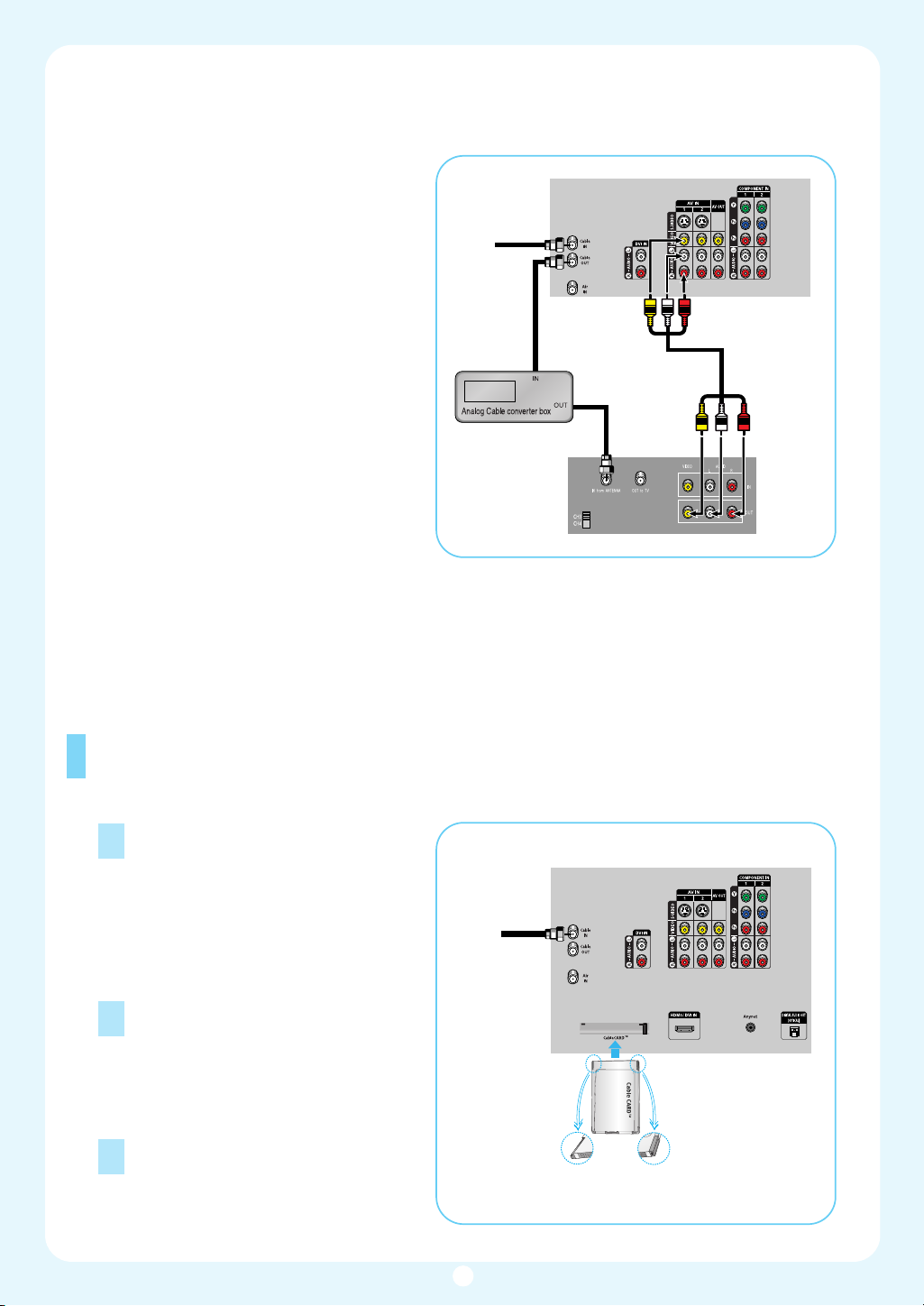
Connecting an Analog Cable Converter Box
This connection allows you to watch cable and premium channels. You should keep your TV
selected to “Cable IN” so that you can use the TV features. When viewing premium channels, select “Air IN” and tune the TV to channel 3 or 4 (whichever channel is vacant in your
area), then use the converter box to change channels. You will need two coaxial cables.
• When you use a converter box
with your TV, there may be features that you can not program
From
Cable
3
using the remote control, such
as programming your favorite
channels and blocking channels.
• The output from "Cable Out" is
not available when "Air/CATV"
is set to "Cable" in the PIP
menu.
Page 4
Connecting an Analog Cable Converter Box and a VCR
This connection allows you to watch and
record basic and premium cable channels,
as well as watch videotapes. You should
keep your TV selected to “Cable IN” so that
you can use the TV’s features. When viewing premium channels or recording with the
VCR, select “Air IN” (whichever channel is
vacant in your area), then use the converter
box to change channels.
Caution: If you want to record one channel
while watching another channel, a splitter
(not included) must be added between the
cable and “Cable IN”. One output of the
splitter goes to “Cable OUT” and the second output is connected to IN on the cable
converter box.
If you have a mono VCR, connect L/Mono
to VCR Audio OUT using only one audio
cable.
If you have an S-VHS VCR, use the S-Video
connections and remove the video cable. Do not connect the video cable and the S-Video
cable to video1 simultaneously.
When you use a converter box with your TV there may be features that you can not program
using the remote control, such as programming your favorite channels and blocking channels.
From
Cable
TV Rear Panel
Stereo VCR
Connecting CableCARD
You must obtain a CableCARD from a local cable service provider.
Insert the CableCARD into the
1
“CableCARD” slot and the message
“CableCARD Inserted” is displayed on
the screen. If the channel information
does not already exist, the message
“Updating Channel List” is displayed
during channel information configuration.
The pairing information containing a
2
telephone number, CableCARD ID,
Host ID and other information will be
displayed in about 2~3 minutes. If an
error message is displayed, please
contact your Service Provider.
When channel information configu-
3
ration is finished, the message
“Updating Completed” is displayed.
It indicates that the channel list is
now updated.
Incoming
Cable or
Antenna
4
TV Rear Panel
Please insert the
card as shown.
Page 5
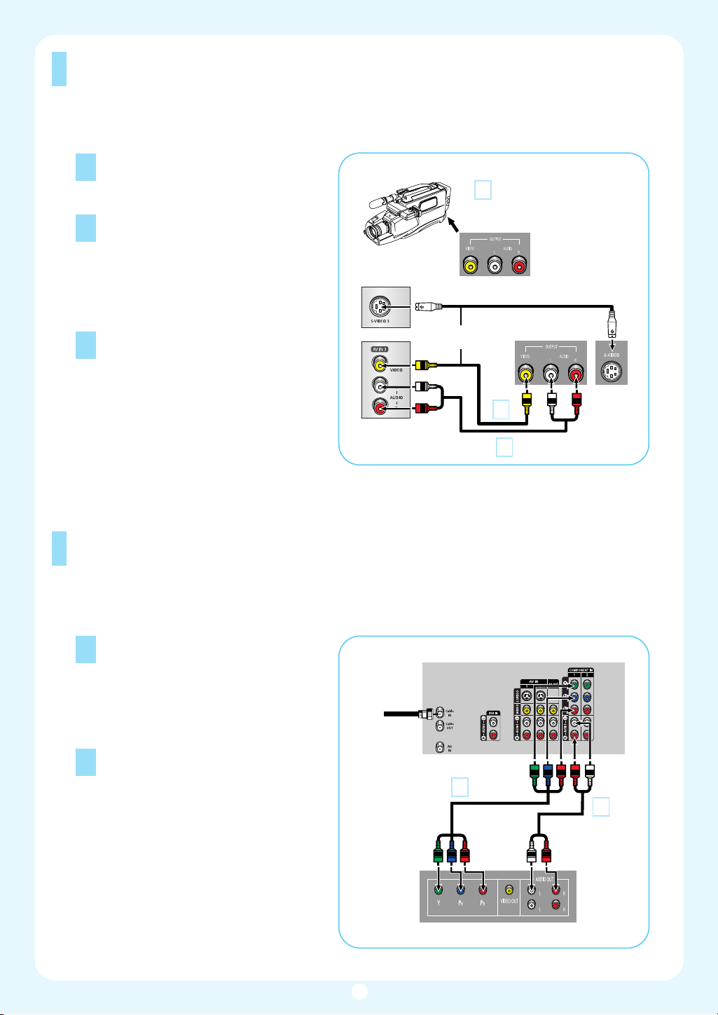
Connecting a Camcorder
The side panel jacks on your TV make it easy to connect a Camcorder to your TV.
You can use your camcorder to view tapes without using a VCR.
Locate the A/V output jacks on the
1
camcorder. They are usually found on
the side or back of the camcorder.
Connect a set of audio cables
2
between the AUDIO IN jacks on the
TV and the AUDIO OUT jacks on the
camcorder. If you have a mono
Camcorder, connect L(mono) to the
Camcorder audio out using only one
audio cable.
Connect a video cable between the
3
VIDEO IN (or S-VIDEO IN) jack on
the TV and the VIDEO OUT jack on
the Camcorder. The audio-video
cables shown here are usually
included with a Camcorder. (If not,
check your local electronics store.) If
your Camcorder is stereo, you need
to connect a set of two cables.
TV Rear of right side
1
Camcorder
Output Jacks
or
Camcorder
3
2
Connecting a DVD Player
The rear panel jacks on your TV make it easy to connect a DVD player to your TV.
Connecting to Y,P
Connect a set of audio cables
1
between the COMPONENT (1 or 2)
audio (L,R) in jacks on the TV and the
AUDIO OUT jacks on the DVD player.
To enable Component video viewing,
2
connect a set of video cables
between the COMPONENT (1 or 2)
VIDEO (Y, P
and VIDEO (Y/P
jacks on the DVD player.
Note: For an explanation of
Component video, see your DVD
player's owner's manual.
B,PR
B, PR) in jacks on the TV
or Y/CB/CR) OUT
R
B/P
Incoming
Cable or
Antenna
TV Rear Panel
2
DVD Player
1
5
Page 6

Connecting to Audio and Video Jacks
Connect a set of audio cables
1
between the Audio in (1 or 2) jacks on
the TV and the AUDIO OUT jacks on
the DVD player.
Connect a video cable between the
2
VIDEO IN (1 or 2) jack on the TV and
the VIDEO OUT jack on the DVD
player.
Incoming
Cable or
Antenna
TV Rear Panel
Connecting a DTV Set-Top Box
Connecting to Y,PB,P
Connect a set of audio cables
1
between the COMPONENT (1 or 2)
audio (L,R) in jacks on the TV and the
AUDIO OUT jacks on the Set-Top
Box.
Connect a set of video cables
2
between the COMPONENT (1 or 2)
VIDEO (Y, P
and VIDEO (Y/P
jacks on the Set-Top Box.
Note: For an explanation of
Component video, see your Set-Top
Box owner's manual.
B
R
, PR) in jacks on the TV
B/PR or Y/CB/CR) OUT
Incoming
Cable or
Antenna
TV Rear Panel
2
DVD Player
1
1
2
DTV Set-Top Box
6
Page 7

Connecting to DVI (Digital Visual Interface)
Connect a set of audio cables
1
between the DVI audio (L,R) in jacks
on the TV and the AUDIO OUT jacks
on the Set-Top Box.
Connect an HDMI/DVI video cable
2
between the HDMI/DVI IN jack on
the TV and the DVI OUT jack on the
Set-Top Box.
• Requires a Cable Converter.
Incoming
Cable or
Antenna
TV Rear Panel
2
DTV Set-Top Box
1
Connecting to HDMI (High Definition Multimedia Interface)
Connect an HDMI cable between the
1
HDMI/DVI IN jack on the TV and the
HDMI OUT jack on the Set-Top Box.
TV Rear Panel
• Make sure the HDMI/DVI
source's power is on, or you
will be unable to select it in the
menu's source list.
Incoming
Cable or
Antenna
7
DTV Set-Top Box
Page 8

Connecting a Digital Audio System
There are many types of digital audio systems on the market today.
A simplified illustration of an audio system is shown below. For more information, see your
audio system owner’s manual.
If your audio system has a optical dig-
1
ital audio input, connect to the “DIGITAL AUDIO OUT(OPTICAL)” jack on
the TV.
Be certain to remove the black cover
from the optical output before inserting the cable.
• OPTICAL: converts the electric
signal into an optical light signal, and transmits it through
glass fibers. A transmission
system of digital audio in the
form of a light wave, S/PDIF
format using a glass conductor.
See page 78 to set the digital
output format (Dolby Digital or
PCM) appropriate to you digital
audio component.
TV Rear Panel
Connecting to an Analog Amplifier
The “AUDIO OUT” terminals cannot
1
be used for external speakers. You
must hook them up to an amplifier.
When an audio amplifier is connected
to the “AUDIO OUT” terminals:
Decrease the gain (volume) of the
audio amplifier, and adjust the volume
level with the volume control on the
TV.
TV Rear Panel
8
Page 9

Remote Control
You can use the remote control up to about 23 feet from the TV. When using the remote
control, always point it directly at the TV. You can also use your remote control to operate
your VCR, Cable box, DVD player or Samsung Set-Top Box.
Œ
POWER
Turns the TV on and off.
´
P.MODE
Adjust the TV picture by selecting
one of the preset factory settings (or
select your personal, customized
picture settings.)
ˇ
ANTENNA
Press to select “AIR” or “CABLE”.
¨
CHANNEL NUMBER
Press to directly tune to a particular
channel.
ˆ
-
Press to select additional channels
(digital and analog) being broadcast
by the same station. For example, to
select channel “54-3”, press “54”,
then press “-” and “3”.
Ø
VOL +, VOL -
Press to increase or decrease
the volume.
∏
MUTE
Press to mute the TV sound.
”
ANYNET
Runs the Anynet view functions and
sets up Anynet devices.
’
MENU
Displays the main on-screen menu.
˝
CH.LIST
Displays the channel list.
Ô
FAV.CH (Favorite
Channel)
Press to switch between your
favorite channels.
MODE
Selects a target device to be
controlled by the Samsung
remote control (i.e., TV, STB,
VCR, CABLE, or DVD).
Ò
PRE-CH
Tunes to the previous channel.
Ú
SOURCE
Press to display all of the available
video sources (i.e., TV, Set-Top box,
VCR, DVD, DTV).
Æ
CH /
Press to change channels.
Moves from one set of screen information to the next in TV Guide
menu.
ı
INFO
Press to display information on the
TV screen.
˜
EXIT
Press to exit the menu.
¯
▲, ▼, œ, √, ENTER
Press to select highlight up, down,
left, or right. While using the onscreen menus, press the ENTER to
activate (or change) a particular
item.
˘
MTS (Multichannel
Television Stereo)
Press to choose Stereo, Mono or
SAP (Secondary Audio Program).
¿
PIP (Picture In Picture)
Displays the available channels in
sequence. (These buttons change
channels in the PIP window only.)
¸
STILL
Press to pause the current screen.
˛
ASPECT
Press to change the screen size.
◊
SRS
Activates TruSurround.
±
DNIe (Digital Natural
Image engine)
Activates DNIe.
≠
SET
Used during set up of this remote
control, so that it will work compatibly with other devices (Set-Top box,
VCR, Cable box, DVD, etc.)
–
SLEEP
Press to select a preset time interval
for automatic shut off.
—
PIP CONTROLS
CH / ; Press to display the available channels in sequence. (These
buttons change channels in the PIP
window only.)
÷
CAPTION
Controls the caption decoder.
®
VCR/DVD CONTROLS
Controls VCR or DVD functions:
Rewind, Stop, Play/Pause, Fast
Forward.
∑
RESET
If your remote control is not functioning properly, take out the batteries
and press the reset button for about
2~3 seconds. Re-insert the batteries
and try using the remote control
again.
9
Page 10

Turning the TV On and Off
Press the POWER button on the remote control.
You can also use the POWER button on the front panel.
Viewing the Menus and On-Screen Displays
The on-screen menu system allows you to control the settings of your TV. Access the onscreen menu system by pressing the Menu button on the remote control. Once the onscreen menu appears, use the
menu items and make adjustments. You can also view the on-screen menu system and
make some adjustments using the TV’s side panel buttons.
Viewing the Menus
Before your television can begin memorizing the available channels, you must specify the type of
signal source that is connected to the TV (i.e., an antenna or cable system).
…/†/œ/√/ENTER buttons on your remote control to select
Press the MENU button.
1
The main menu is displayed.
There are six menu groups: “Input”,
“Picture”, “Sound”, “Channel”, “Setup”,
and “Guide”.
Input
Source List : TV
Edit Name
Picture
Anynet
Sound
Channel
Setup
Guide
Press the EXIt button to exit.
3
Input
Move Enter Exit
√
√
Viewing the Display
Press the INFO button on the remote control.
The TV displays the current channel, the status of certain picture and sound settings and
the current time.
The information displayed varies according to
the selected source.
Press the … or † button to select an item
2
you want in the menu.
Press the
œ, √ or ENTER button to dis-
play, change, or use the selected items.
Use the ENTER button to enter items in
the menu.
Input
Picture
Sound
Channel
Setup
Guide
CABLE 3
Picture Mode
Sound Mode
MTS
Caption
V-Chip
No Time Information
Standard
Custom
Stereo
Off
Off
Mode : Standard
Color Tone : Warm1
Size : 16:9
Digital NR : On
DNIe : On
My Color Control
▼ More
Picture
√
√
√
√
√
√
Move Enter Return
10
Page 11

Memorizing the Channels
Your TV can memorize and store all of the available channels for both “off-air” (antenna) and cable channels.
After the available channels are memorized, use the CH and CH buttons to scan through the channels. This
eliminates the need to change channels by entering the channel digits. There are three steps for memorizing
channels: selecting a broadcast source, memorizing the channels (automatic) and adding and deleting channels (manual).
Selecting the Video Signal Source
Before your television can begin memorizing the available channels, you must specify the type of
signal source that is connected to the TV (i.e., an antenna or cable system).
Press the MENU button. Press the … or
1
† button to select “Channel”, then press
the ENTER button.
Input
Picture
Sound
Channel
Setup
Guide
Press the ENTER button to select
2
“Antenna”.
Press the
Channel
Antenna : Cable
Auto Program
Add/Delete
Favorite Channels
Name
Fine Tune
▼ More
Move Enter Return
√
√
√
√
√
√
… or † button to select “Air” or
“Cable”, then press the ENTER button.
Input
Picture
Sound
Channel
Setup
Guide
Channel
Antenna : Cable
Auto Program
Add/Delete
Favorite Channels
Name
Fine Tune
▼ More
Air
Cable
Move Enter Return
Press the … or † button to select “Auto
3
Program”, then press the ENTER button.
Input
Picture
Sound
Channel
Setup
Guide
Channel
Antenna : Cable
Auto Program
Add/Delete
Favorite Channels
Name
Fine Tune
▼ More
Move Enter Return
√
√
√
√
√
√
• All available DTV and analog
channels are automatically stored
in memory.
11
Page 12

Press the … or † button to select the
4
Antenna connection, then press the
ENTER button.
• Air : “Air” antenna signal
Cable : “Cable” antenna signal
Air+Cable : “Air” and “Cable” antenna
signals
• If the CableCARD is inserted into
the“CableCARD” slot on the rear panel,
“Cable” and “Air+Cable” are not available.
Input
Picture
Sound
Channel
Setup
Guide
Auto Program
Select the antennas to memorize
Air
Cable
Air+Cable
Move Enter Return
Start
Start
Start
When selecting Cable TV system:
Press the
… or † button to select
“Cable”, then press the ENTER button.
Press the
… or † button to select Analog
or Digital “STD”,"HRC" or "IRC" then
press the ENTER button.
• STD, HRC and IRC identify various
types of cable TV systems.
Contact your local cable company to
identify the type of cable system that
exists in your particular area.
At this point the signal source has been
selected. Proceed to “Storing Channels
in Memory”.
Press the √ button to select “Start”, then
5
press the ENTER button to start the auto
program. The TV begins memorizing all
available stations. Press the ENTER button at any time to interrupt the memorization process.
Press the EXIT button to exit.
• The TV MUST be connected to an
antenna in order to receive digital TV
signals. Even if a particular channel is
deleted from the memory, you can
always tune to that channel directly by
using the number buttons on the remote
control.
Auto Program
Select the cable system.
Input
Analog
Picture
Sound
Channel
Setup
Guide
Auto Program in progress
STD ✔
HRC
IRC
Digital
STD ✔
HRC
IRC
Move Enter Return
Auto Program
AIR Channel 44
Stop
Enter Return
Start
Input
Picture
Sound
Channel
Setup
Guide
Auto Program
Select the cable system.
Analog
STD
HRC ✔
IRC
Digital
STD ✔
HRC
IRC
Move Enter Return
Start
12
Page 13

Viewing an External Signal Source
Use the remote control to switch between viewing signals from connected equipment,
such as a VCR, DVD, Set-Top box or the TV source (broadcast or cable).
Setting the Signal Source
Press the MENU button. Press the
1
ENTER button to select “Input”.
Input
Picture
Sound
Channel
Setup
Guide
Source List : TV
Edit Name
Anynet
Input
√
√
Move Enter Return
Alternate method
Press the SOURCE button on the remote
control repeatedly to select an external signal
source.
Press the ENTER button to select
2
“Source List”. Press the
… or † button to
select a signal source, then press the
ENTER button.
Source List
TV
Input
Picture
Sound
Channel
Setup
Guide
AV1
AV2
AV3
S-Video1
S-Video2
▼ More
---
---
---
---
---
Move Enter Return
• When you connect equipment to the TV,
you can choose between the following
sets of jacks: “AV1”, “AV2”, “S-Video1”,
“S-Video2”, “Component1”,
“Component2” or “HDMI/DVI” on the
TV’s rear panel and “AV3” or “S-Video3”
on the TV’s side panel.
• HDMI input can be selected only when
the external device is turned on and
connected to the TV.
AV1
Viewing Position
To optimize your viewing comfort, please follow the guidelines below for viewing distance.
If viewing for an extended period of time, sit as far back from the screen as possible.
13
Page 14

Replacing the Lamp
Why do I need to replace the lamp?
The lamp used in a DLP TV has a limited lifespan. For the best screen quality it needs to be
replaced periodically. After replacing the lamp, the screen quality will be bright and clear as
new.
When do I need to replace it?
It should be replaced when the screen becomes darker, less clear or when all three LEDs on
the front (Timer, Lamp, & Temp.) are flashing.
Check before lamp replacement
1. The lamp must be the same code number and type.
2. The lamp type is indicated on the right side of the TV. It is also indicated on the lamp
case.
3. After checking the code number for the lamp, give the code number to the store where
you purchased the TV or to a Samsung Service center.
Caution
1. Replace with the correct code numbered lamp to avoid damage to the TV.
2. Turn the power off and wait for 30 minutes before replacing the lamp as it will be hot.
3. Do not touch the glass part of the lamp with your bare hands nor insert any foreign object
inside the cover as it may cause poor screen quality, electric shock or fire.
4. Do not place the old lamp near flammable objects or within the reach of children.
5. Be sure to connect this TV directly to an AC wall outlet. If the TV's AC plug is connected
to a cable box or other source, it will not allow for proper cool down time.
For replacement, you will need a 5.91-Inch screwdriver and a pair of gloves.
Unplug TV, then use a screwdriver to
1
remove the screw.
Remove the Lamp cover.
2
Remove the screw securing the Lamp by
3
using a screwdriver.
Separate the Lamp from the engine by
4
holding the handle and pulling it out.
To reinstall the Lamp, follow these steps
5
in reverse order.
• Be sure the replacement Lamp is the
same type.
• After replacing the lamp, align the lamp
cover with the groove and secure the
screws.
• The TV will not turn on if the lamp cover
is not correctly closed (as this will activate the protective circuit).
14
Page 15

Front Panel LED Indicators
The three lights on the front panel indicate the status of your TV.
: Light is On : Light is Blinking : Light is Off
TIMER
LAMP STAND BY/TEMP
Indication
Standby state.
The picture will automatically appear in about 15 seconds.
Auto Timer ON/OFF has been set and the set will automatically be
turned on in about 25 seconds.
A cooling fan inside the set is not operating normally.
Lamp cover on rear of the set is not properly shut.
Check if the ventilation hole on the rear of the set is blocked,
because if the inner temperature is too high, the power will shut off.
Lamp may be defective. Please contact a certified technician.
• It takes about 30 seconds for the TV to warm up, so normal brightness may not appear immediately.
• The TV has a fan to keep the inside lamp from overheating. You’ll occasionally hear it working.
Troubleshooting
If the TV seems to have a problem, first try this list of possible
problems and solutions. If none of these troubleshooting tips apply,
then call your nearest Samsung authorized service center.
Poor picture quality.
Try another channel.
Adjust the antenna.
Check all wire connections.
No color, wrong colors or tints.
Make sure the program is broadcasted in color.
Adjust the picture settings.
Your remote control does not
operate your TV.
Press the Mode button to put your
remote control into TV mode.
Make sure the remote has batteries.
Poor sound quality.
Try another channel.
Adjust the antenna.
Make sure the MUTE button is off.
Picture rolls vertically.
Adjust the antenna.
Check all wire connections.
If you are using a VCR, check the tracking.
The TV won’t switch on.
Make sure the wall outlet is working.
Make sure the TV is plugged in.
Make sure the remote has batteries.
No picture or sound.
Try another channel.
Press the SOURCE button.
Make sure the TV is plugged in.
Check the antenna connections.
The TV operates erratically.
Unplug the TV for 30 seconds, then
try operating it again.
Digital broadcasting screen
problem.
Please check the digital signal
strength and input antenna.
• The display panel used for the DLP TV is composed of many tiny pixels.
These pixels may occasionally appear on the screen.
15
Page 16

Memo
16
 Loading...