

Samsung HG40NB670FFXZA, HG46NB677FFXZA, HG46NB670FFXZA, HG32NB677BFXZA, HG28NB670BFXZA User Manual
...
LED TV
Installation manual
imagine the possibilities
Thank you for purchasing this Samsung product.
To receive more complete service, please register
your product at
www.samsung.com/register
Model Serial No.
[HG670677-ZA]Install Guide-ENG.indd 1 2013-02-25 �� 2:19:09
Figures and illustrations in this User Manual are provided for reference only and may differ from actual product appearance.
Product design and specifications may be changed without notice.
Introduction
This TV B2B (Business to Business) model is designed for hotels or the other hospitality businesses, supports a variety of special functions, and lets you
limit some user (guest) controls.
Operational Modes
This TV has two modes : Interactive and Stand-alone mode.
• Interactive mode : In this mode, the TV communicates with and is fully or partially controlled by a connected Set Back Box (SBB) or Set Top Box
(STB) provided by a hospitality SI (System Integration) vendor. When the TV is initially plugged in, it sends a command that attempts to identify the
SSB or STB connected to it. If the TV identifies the SBB or STB and the SBB or STB identifies the TV, the TV gives full control to the SBB or STB.
• Stand-alone mode : In this mode, this TV works alone without an external SBB or the STB.
The TV has a Hotel (Hospitality) Menu that lets you easily set its various hospitality functions. Please see pages 17 to 21.
The Menu also lets you activate or de-activate some TV and hospitality functions so you can create your optimal hospitality configuration.
Still image warning
Avoid displaying still images (such as jpeg picture files) or still image elements (such as TV channel logos, panorama or 4:3 format images, stock or news
bars or crawls) on the screen. Displaying still pictures continually can cause uneven screen wear, which will affect image quality. To reduce the chance that
this effect will occur, please follow the recommendations below:
• Avoid displaying the same TV channel for long periods.
• Always try to display a full screen image.
• Reduce brightness and contrast to help to prevent the occurrence of after-images.
• Frequently use all TV features designed to reduce image retention and screen burn-in. Refer to the proper user manual section for details.
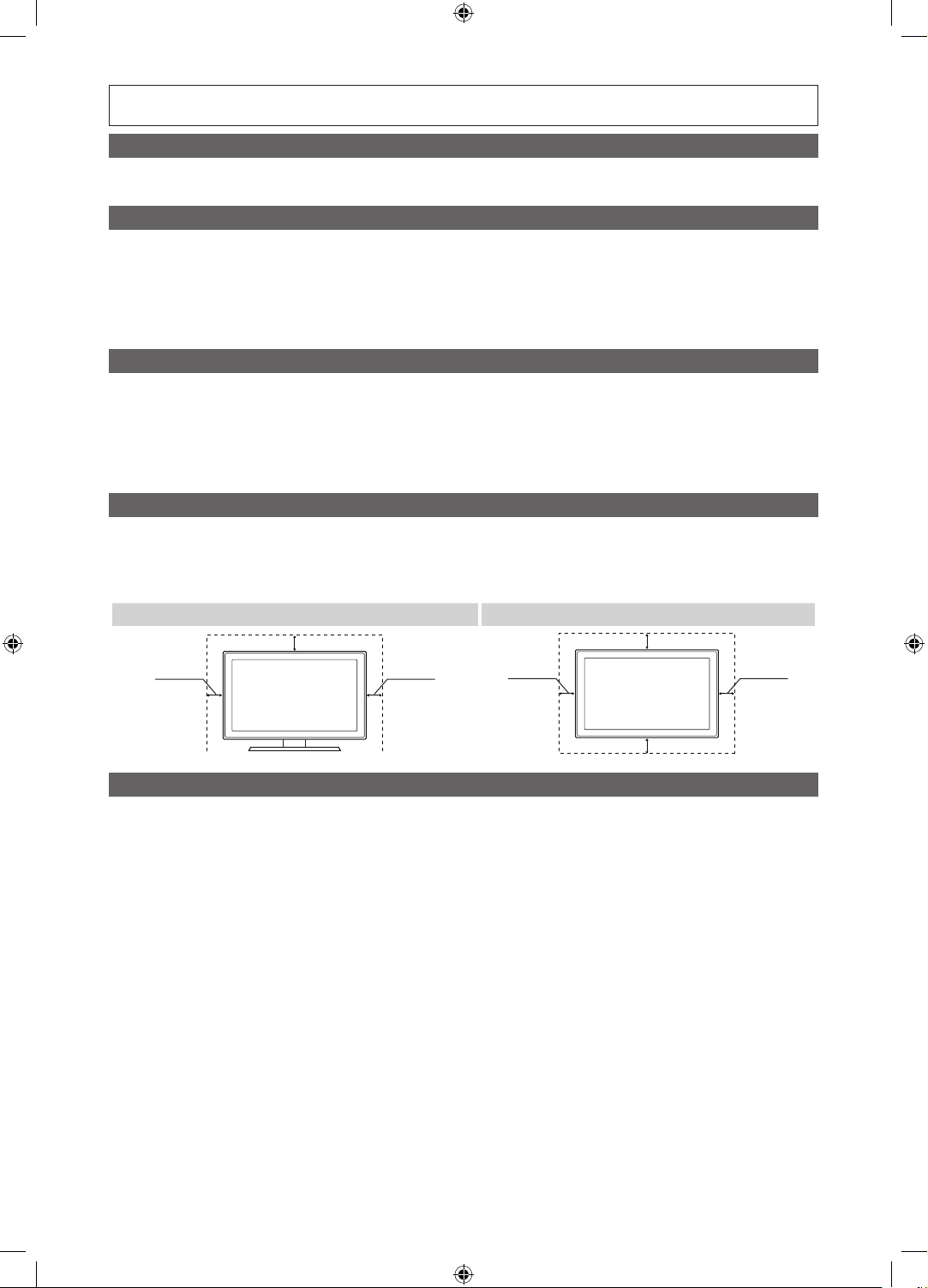
Ensuring Proper Ventilation
When you install the TV, maintain a distances of at least 4 inches between the TV and other object (walls, cabinet sides, etc.) to ensure proper ventilation.
Failing to maintain proper ventilation may result in a fire or problems with the product caused by an increase in its internal temperature.
When using a stand or wall-mount, use parts provided by Samsung Electronics only.
✎
Using parts provided by another manufacturer may cause difficulties with the product or result in injury caused by the product falling.
✎
Installation with a stand. Installation with a wall-mount.
4 inches
4 inches4 inches
4 inches
4 inches4 inches
Additional Information
The appearance of the TV and its accessories may differ from the illustrations in this manual, depending on the TV.
✎
Be careful when the you touch the TV. Some parts can be hot.
✎
4 inches
[HG670677-ZA]Install Guide-ENG.indd 2 2013-02-25 �� 2:19:10

Contents
English
y Introduction .............................................................................................................................................................. 2
y Operational Modes ...................................................................................................................................................2
y Still image warning .................................................................................................................................................... 2
y Ensuring Proper Ventilation .......................................................................................................................................2
y Additional Information ...............................................................................................................................................2
y Accessories .............................................................................................................................................................. 4
y Installing the LED TV Stand ....................................................................................................................................... 5
y Assembling the swivel stand (32 inch TVs or larger) ..................................................................................................6
y Using the TV's Controller .......................................................................................................................................... 8
y The Connection Panel ............................................................................................................................................... 9
y Using the TV's Controller ........................................................................................................................................ 11
y Connecting the TV to a SBB or STB of a SI vendor ................................................................................................. 12
y Connecting the RJP (Remote Jack Pack) ................................................................................................................ 15
y Setting the Hotel Option Data .................................................................................................................................17
y Installing the Wall Mount ......................................................................................................................................... 37
y Securing the TV to the Wall ..................................................................................................................................... 38
y Caution of the cover-jack ........................................................................................................................................ 38
y Anti-theft Kensington Lock ...................................................................................................................................... 39
y Specifications .........................................................................................................................................................40
y Dimensions ............................................................................................................................................................. 41
3
[HG670677-ZA]Install Guide-ENG.indd 3 2013-02-25 �� 2:19:10
English
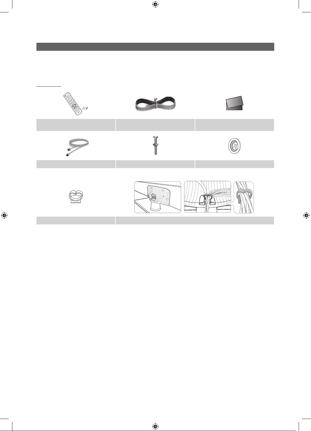
Accessories
✎
Please make sure the following items are included with your LED TV. If any items are missing, contact your dealer.
✎
The items’ color and shape may var y, depending on the model.
✎
The parts for the stand are listed under Stand Components on the following page.
List of Parts
y Remote Control (AA59-00817A) &
Batteries (AAA x 2)
y Data Cable (depending on the model)
y Holder-Wire stand
y Power Cord
y Hotel Mount Kit y Holder Ring (2EA) (46" only)
y Assembling the Holder Wire Stand
y Safety Guide / Quick Setup Guide
(Not available in all locations)
4
[HG670677-ZA]Install Guide-ENG.indd 4 2013-02-25 �� 2:19:12
English
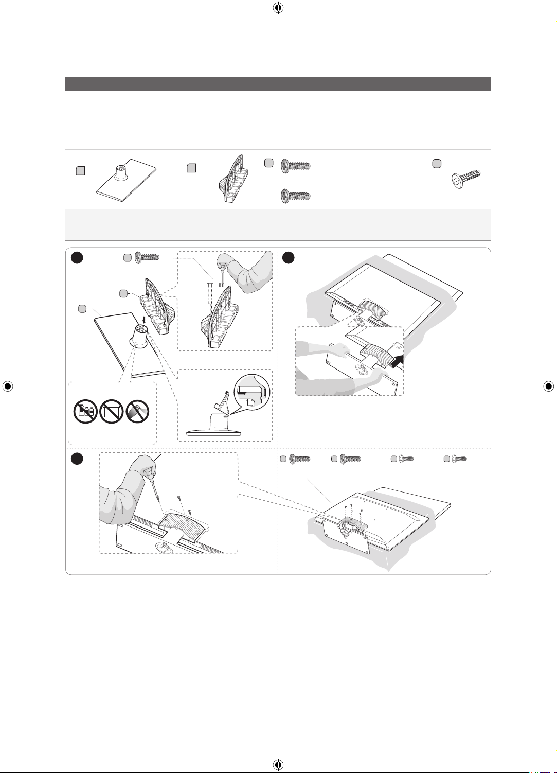
Installing the LED TV Stand
The 32” and larger LED TVs have swivel stands. You can configure these stands so that the TVs swivel 20 degrees left and
right, 60 degrees left and right, or 90 degrees left and right. See page 6.
Components
When installing the stand, use the provided components and parts.
B
A
1 EA
y Stand (differs depending
on the model)
1 2
C
x4
1 EA
y Guide Stand y Screws
C
(M4 X L12)
B
Front
A
Top View
ATTENTION
DO NOT USE
DO NOT USE
CHEMICALS
3
GREASE
DO NOT USE
OIL
Side
C
D
or
x7 (M4 X L12)
or
x8 (M4 X L12, for 40" and
above models)
y Security Screws (3EA)
(4EA, for 40" and above
models)
✎
Place a soft cloth over a table to protect the TV, and
then place the TV on the cloth screen side down.
✎
Insert the Stand Guide into the slot on the bottom of
th e T V.
x3
(M4 X L12)
C
or or or
x3
(M4 X L12, for 40"
and above models)
D
x4
(Security Screw)
D
x4
(Security Screw,
for 40” and above
models)
✎
NOTES
y Make sure to distinguish between the front and back of the Stand and Stand Guide when connecting them.
y Make sure that at least two people lift and move the LED TV.
y The number of screws may differ depending on the model.
5
[HG670677-ZA]Install Guide-ENG.indd 5 2013-02-25 �� 2:19:14
English
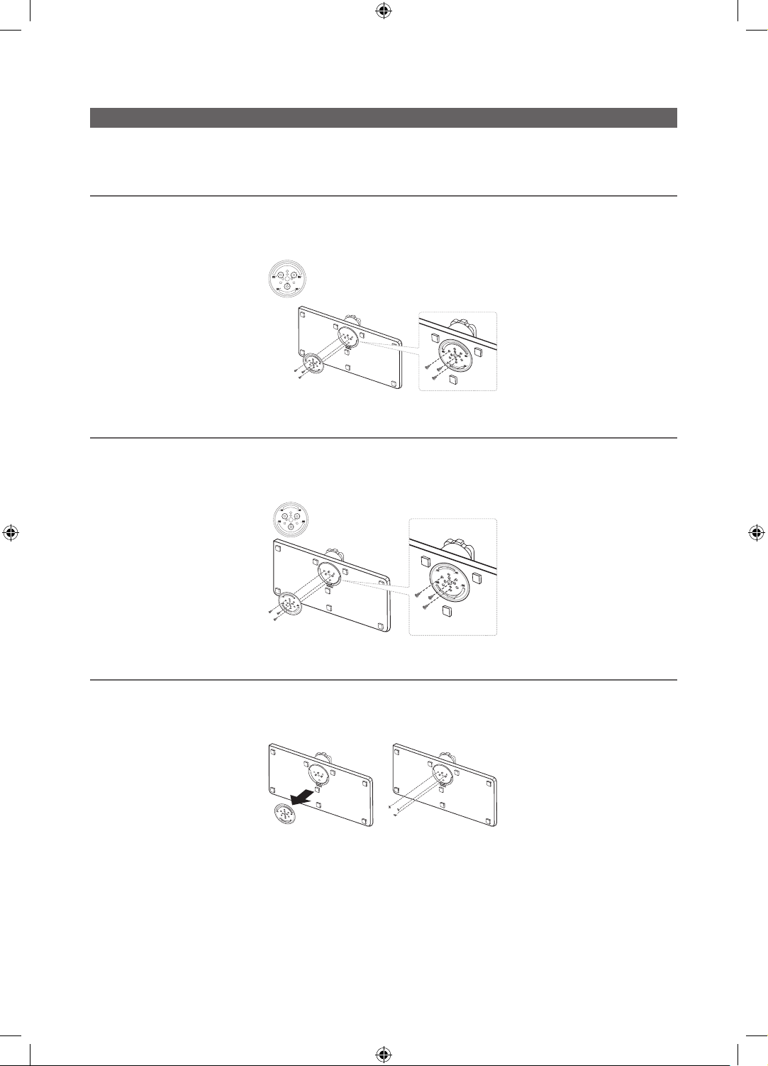
Assembling the swivel stand (32 inch TVs or larger)
The 32” and larger LED TVs have swivel stands. You can configure these stands so that the TVs swivel 20 degrees left and
right, 60 degrees left and right, or 90 degrees left and right using the BRACKET HOLDER SWIVEL.
¦ 20° swivel
To configure the TV so that it swivels 20° left and right, insert the prong on the bottom of the stand through the curved hole
in the Bracket Holder Swivel marked 20°. Then, fix the Bracket Holder Swivel to the stand using the three supplied screws as
shown to the left.
¦ 60° swivel
To configure the TV so that it swivels 60° left and right, insert the prong on the bottom of the stand through the curved hole
in the Bracket Holder Swivel marked 60°. Then, fix the Bracket Holder Swivel to the stand using the three supplied screws as
shown to the left.
¦ 90° swivel
To configure the TV so that it swivels 90° left and right, remove the Bracket Holder Swivel, and then screw the three supplied
screws into the stand as shown to the left.
6
[HG670677-ZA]Install Guide-ENG.indd 6 2013-02-25 �� 2:19:15
English
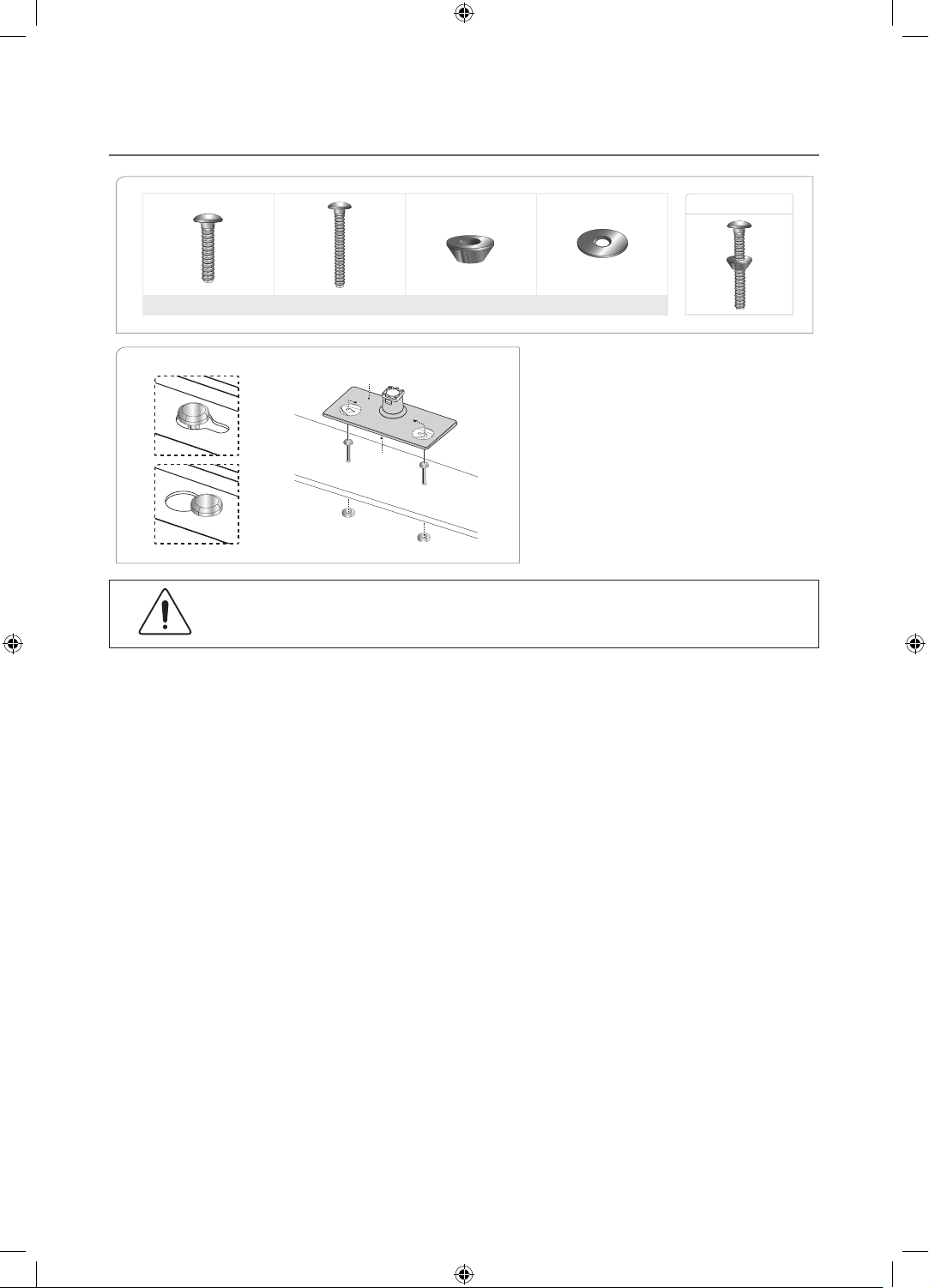
¦ Hotel Mount Kit
Short Bolt (2EA) Long Bolt (2EA) Nut (2EA) Washer (2EA)
Top
Affix the stand to a flat surface such as a
Bottom
dresser top, desk top, or entertainment center
as shown.
Bolt + Nut
WARNING:
the Hotel Mount Kit as described in these instructions.
To prevent injury, you must attach this TV securely to the floor, a table, a dresser top, etc. with
7
[HG670677-ZA]Install Guide-ENG.indd 7 2013-02-25 �� 2:19:16
English
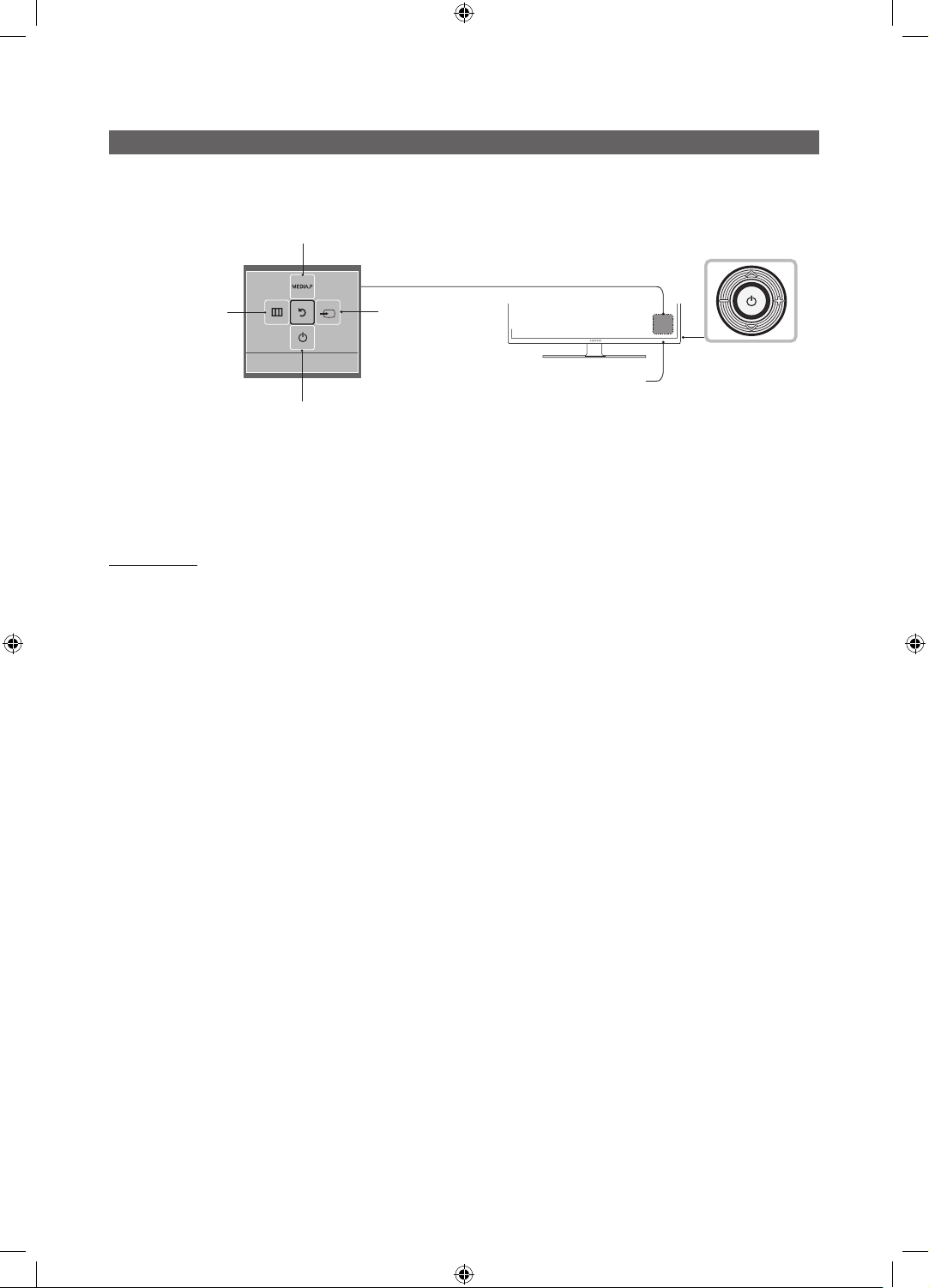
Using the TV's Controller
The TV’s Controller, a small joy stick like button on the rear right side of the TV, lets you control the TV without the remote
control.
Selecting the Media Play
Selecting the Menu
Return
Power off
✎
The product color and shape may vary depending on the model.
✎
To exit the menu, press the Controller for more than 1 second.
✎
When selecting a function by moving the controller backwards/forwards/left/right, be sure not to press up on the
controller. If you press up first, it will not operate correctly.
Standby mode
Your TV enters Standby mode when you turn it off and continues to consume a small amount of electric power. To be safe
and to decrease power consumption, do not leave your TV in standby mode for long periods of time (when you are away on
vacation, for example). It is best to unplug the power cord.
Selecting a Source
Function menu
Remote control sensor
TV Controller
The image is drawn as if
you are facing the front
side of the TV.
8
[HG670677-ZA]Install Guide-ENG.indd 8 2013-02-25 �� 2:19:17
English
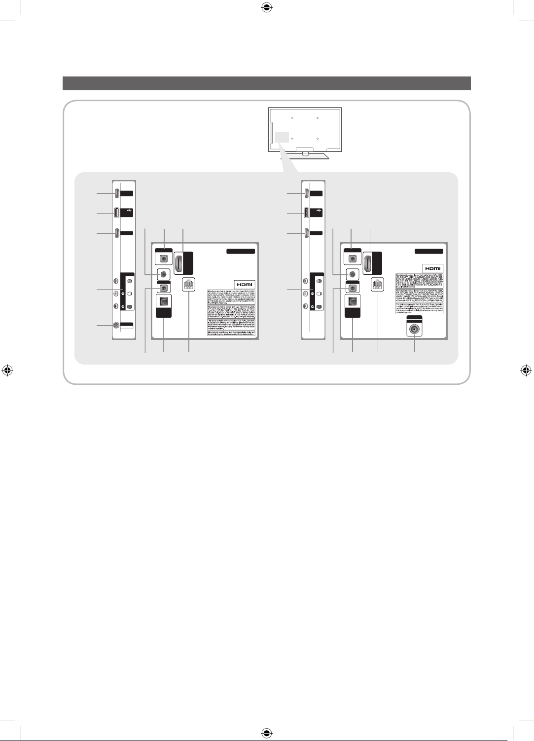
The Connection Panel
1
2
1
3
4
✎
Whenever you connect an external device to your TV, make sure that the T V and the device are turned off.
✎
When connecting an external device, match the color of the connection terminal to the cable.
HDMI IN 2
(DVI)
USB
(5V 0.5A)
/ CLONING
HDMI IN 1
AV IN
AUDIOVIDEO
ANT IN
AIR/CABLE
9
5
DVI AUDIO IN
EX-LINK
AUDIO OUT
DIGITAL
AUDIO OUT
(OPTICAL)
6 7
1
2
18
[32/40/46" Models] [28" Model]
HOSPITALITY TV
HDMI IN
3 (ARC)
DATA
1
3
HDMI IN 2
(DVI)
USB
(5V 0.5A)
/ CLONING
HDMI IN 1
AV IN
AUDIOVIDEO
DVI AUDIO IN
EX-LINK
AUDIO OUT
DIGITAL
AUDIO OUT
(OPTICAL)
6 475
189
HOSPITALITY TV
HDMI IN
3 (ARC)
DATA
ANT IN
AIR/CABLE
1 HDMI IN 1, 2 (DVI), 3 (ARC) : Connects to the HDMI jack of a device with an HDMI output.
✎
No separate sound connection is needed for an HDMI to HDMI connection. HDMI connections carry both audio
and video.
✎
Use the HDMI IN 2 jack for a DVI connection to an external device. Use a DVI to HDMI cable or DVI-HDMI adapter
(DVI to HDMI) for the video connection and the DVI AUDIO IN jack for audio. Some DVI or HDMI devices may not
or should not need a DVI AUDIO IN connection for audio.
2 USB / CLONING
– Connector for software upgrades and Media Play, etc.
– Service connection.
3 VIDEO / L-AUDIO-R
– Connect a VIDEO cable to an appropriate external A/V device such a VCR, DVD, or Camcorder.
– Connect audio cables to "L-AUDIO-R" on your TV and the other ends to corresponding audio out jacks on the A/V
device.
9
[HG670677-ZA]Install Guide-ENG.indd 9 2013-02-25 �� 2:19:18

English
4 ANT IN or AIR/CABLE
– To view television channels correctly, the TV must receive a signal from one of the following sources:
– An outdoor antenna / A cable television system / A satellite receiver.
5 AUDIO OUT: Connects to the audio input jacks on an Amplifier/Home Theater.
6 DIGITAL AUDIO OUT (OPTICAL): Connects to a Digital Audio component.
7 DATA
– Used to support data communication between the TV and the external SBB or STB.
– Connects using an RJ-12 type of plug.
8 DVI AUDIO IN: Connects to the audio out jack of an external DVI device using a 1/8th inch stereo phone jack cable.
Some DVI devices may not or should not need this connection audio.
9 EX-LINK : Connect this jack to the jack on the optional RJP (Remote Jack Pack). The RJP allows you to connect external
devices (Camcoders, PCs, DVD players, etc) easily.
10
[HG670677-ZA]Install Guide-ENG.indd 10 2013-02-25 �� 2:19:18
English
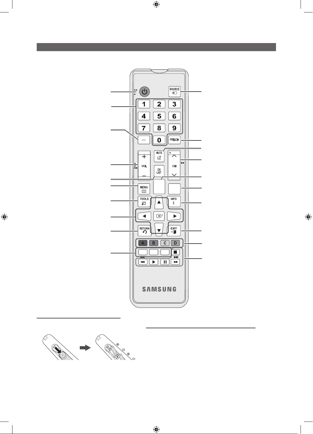
Turns the TV on and off.
Press to access channels directly.
Press to select additional digital channels
being broadcast by the same station. For
example, to select channel ‘54-3’, press
‘54’, then press '-' and ‘3’.
Using the TV's Controller
POWER
Display and select the available video
sources.
Return to the previous channel.
Cut off the sound temporarily.
Adjust the volume.
Display the channel list on the screen.
Display the main on-screen menu.
Quickly select frequently used functions.
Select on-screen menu items and change
Return to the previous menu.
SLEEP: Sets the Sleep Timer.
X
: Turns the 3D image on or off. (Not
CC: Controls the caption decoder.
menu values.
available)
Installing the batteries (Battery size: AAA)
Rear of the Remote
✎
After you have installed the batteries, use a
screwdriver to screw in the screw that holds the
battery cover closed.
Change channels.
HOME: Display the REACH menu if REACH
has been downloaded to the TV.
SLEEP
HOME
X
CONTENT
CC
Use these buttons in Contents Home.
Press to display channel and TV information
on the TV screen.
Exit the menu.
Use these buttons according to the
directions on screen (to perform a function,
display a screen, etc.).
Use these buttons in a specific feature.
Installing Batteries into the Remote (battery size: AAA)
Match the polarity of the batteries to the symbol in the batter
compartment.
✎
Note
Use the remote control within 23~33 feet of the TV.
x
Bright light may affect the performance of the remote
x
control. Avoid using near fluorescent lights or neon signs.
The color and shape of the remote may vary depending on
x
the model.
11
[HG670677-ZA]Install Guide-ENG.indd 11 2013-02-25 �� 2:19:19
English
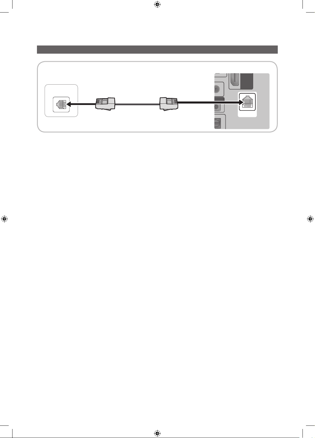
Connecting the TV to a SBB or STB of a SI vendor
HDMI IN
3 (ARC)
IO OUT
DATA
HDMI IN
3 (
)
IO OUT
TV Rear Panel
ETH MODEM
Data Cable
1. Connect the DATA jack of the TV to the ETH MODEM jack of the STB (SBB) with the Data cable.
✎
The "ETH MODEM" jack name that you connect the Data Cable to may differ depending on the SBB or STB type.
ARC
12
[HG670677-ZA]Install Guide-ENG.indd 12 2013-02-25 �� 2:19:19
English
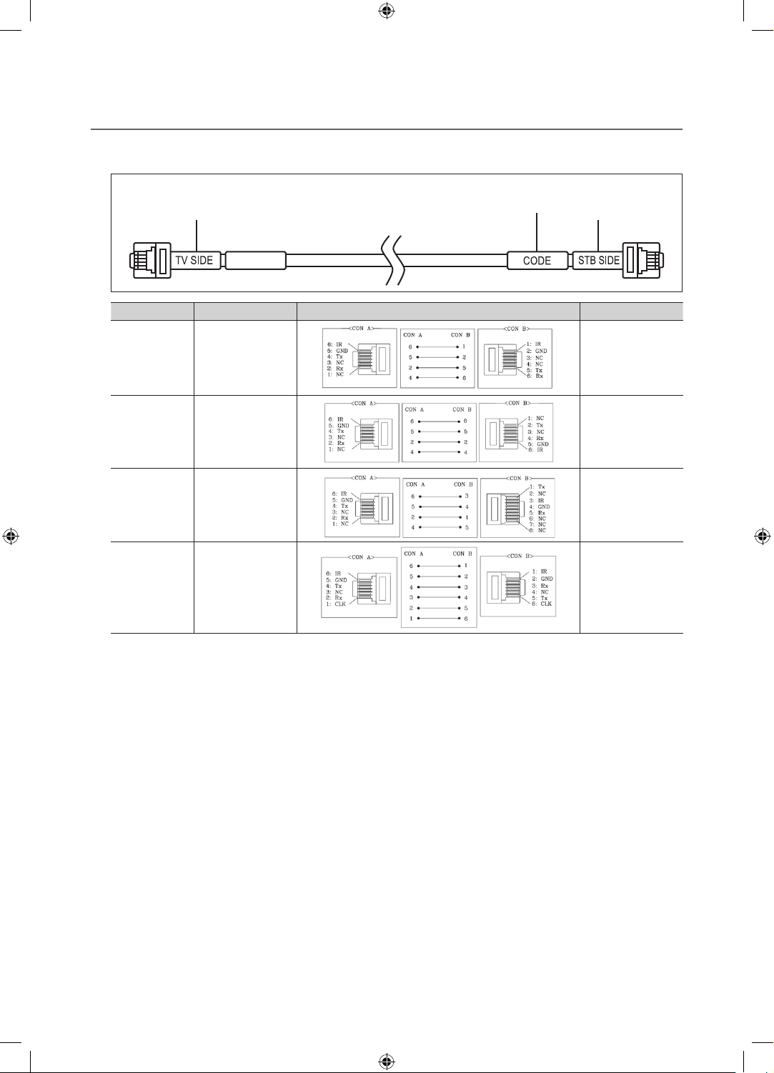
¦ List of SI Vendors and Compatible Data Cables Supplied with the TV
y Confirm you are using the correct data cable for your SI vendor. Refer to the code label on the data cables.
y Contact your nearest dealer or your SI Vendor to buy the data cable not included in the TV.
Confirm the code on the
Note the labeled end. Note the labeled end.
SI Vendor Cable code Pin assign Remark
Samsung
OCC
Enseo
Guest-Tek
NXTV BN39-01011B
nStreams BN39-01110A
BN39-00865B
Code Label
Only Provided with
NB670 and NB677
models.
MTI BN39-01011C
Only Provided with
NB677 models.
13
[HG670677-ZA]Install Guide-ENG.indd 13 2013-02-25 �� 2:19:20
English
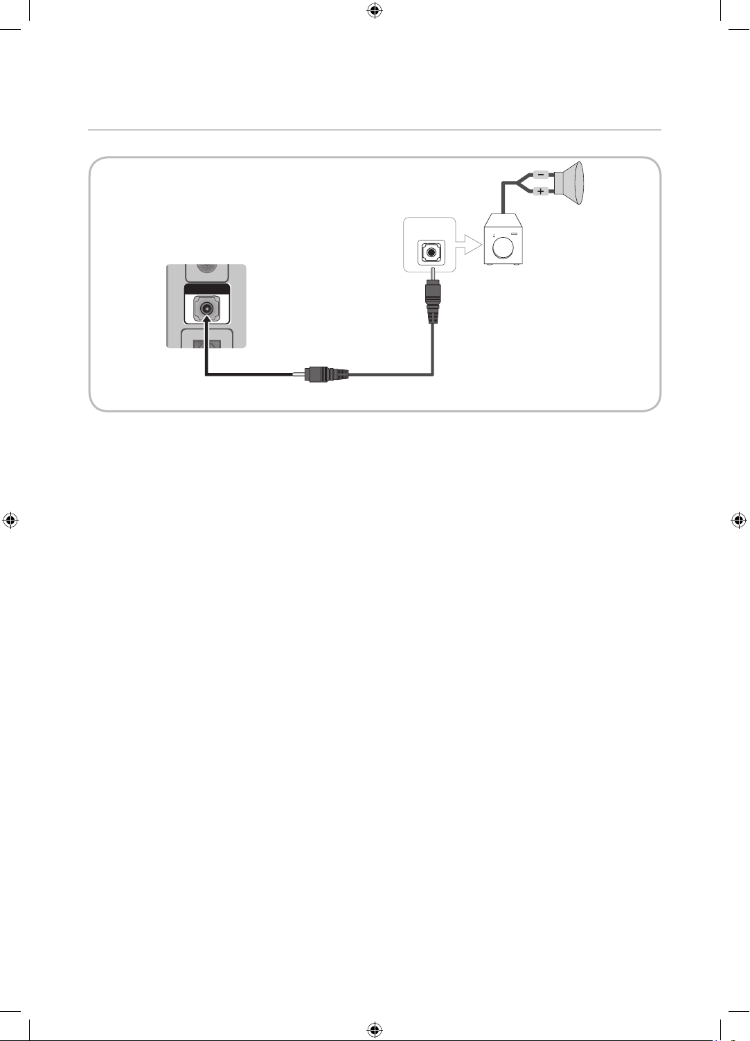
¦ Connecting the Audio Output to an Audio Amplifier
AUDIO OUT
AUDIO IN
TV Rear Panel
1 Stereo cable
1. Connect the AUDIO OUT port of the TV to the Audio In port of an audio amplifier with a stereo cable.
Audio
Amplifier
14
[HG670677-ZA]Install Guide-ENG.indd 14 2013-02-25 �� 2:19:20
English
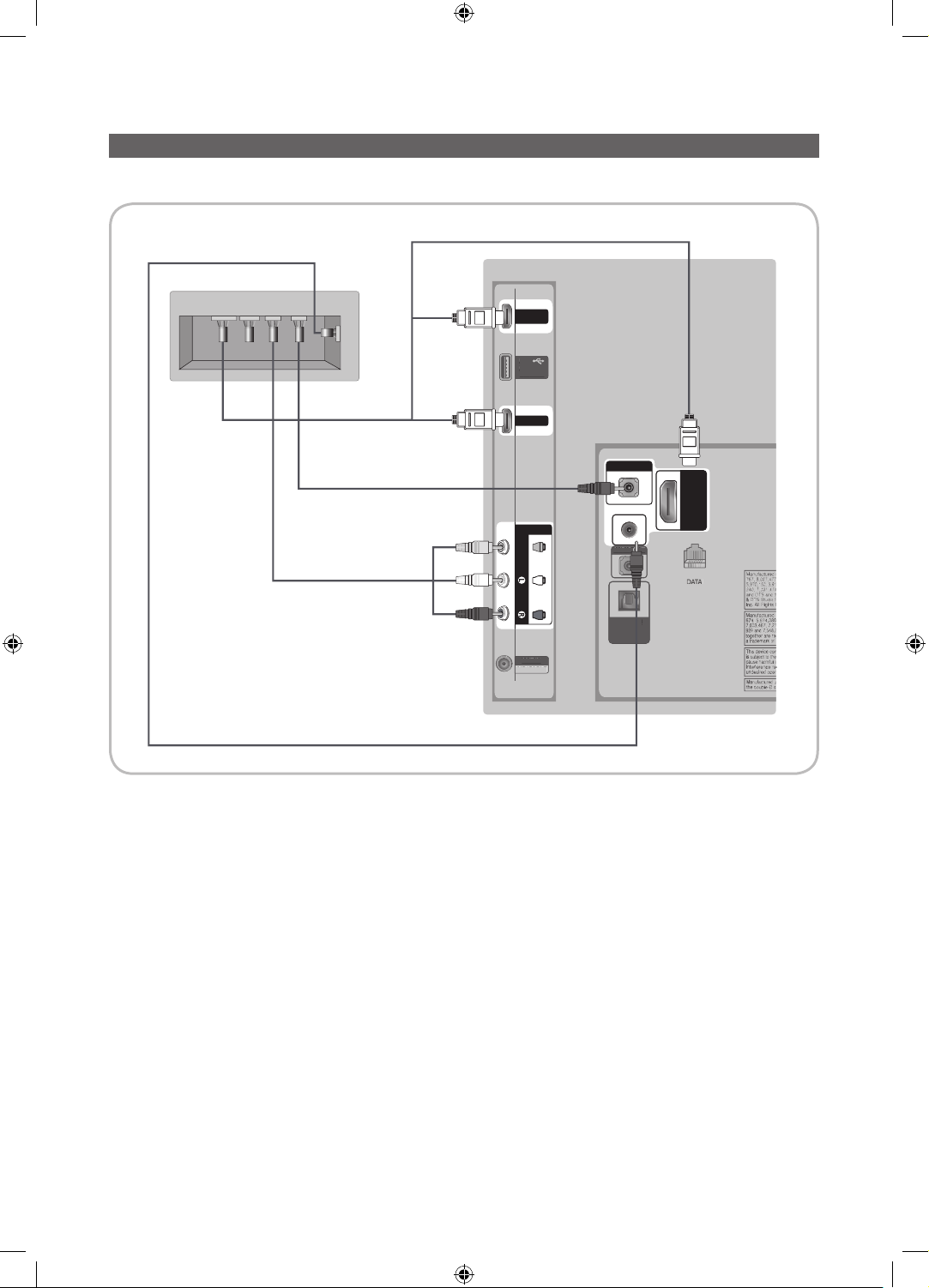
Connecting the RJP (Remote Jack Pack)
(5V 0.5A)
/ CLONING
USB
HDMI IN 2
(DVI)
HDMI IN 1
ANT IN
AIR/CABLE
AV IN
AUDIOVIDEO
HDMI IN
3 (ARC)
DIGITAL
AUDIO OUT
(OPTICAL)
DVI AUDIO IN
AUDIO OUT
EX-LINK
(
)
/
US
E
DIG
L
AUDIO OUT
(
)
A
T
Connect the input jacks on the TV to the RJP. The RJP lets guests connect audio and video sources to the TV.
3 HDMI cable
TV Rear Panel
USB HDMI S-VIDEO
RCA AUDIO/PC
RS/232
B
5V 0.5A
CLONING
RJP Rear
1 PC Audio cable
2 Video / Audio Cable
AIR/CABL
4
1. Connect the DVI AUDIO IN port of the TV to the PC/AUDIO port of the RJP.
2. Connect the AV IN VIDEO/L-AUDIO-R ports of the TV to the RCA port of the RJP.
3. Connect one of the HDMI IN ports of the TV to the HDMI port of the RJP.
4. Connect the EX-LINK port of the TV to the RS/232 port of the RJP.
✎
This Samsung TV is compatible with the Tele Adapt TA-7610 RJP only.
UDIO OU
ITA
OPTICAL
15
[HG670677-ZA]Install Guide-ENG.indd 15 2013-02-25 �� 2:19:21
English
y RJP (Remote Jack Pack): The RJP is a hardware module that has different Audio Video inputs (A/V, Audio, PC
and HDMI) and corresponding outputs. The corresponding outputs are connected from the RJP to the TV. The RJP
communicates with the TV via RS232. The RJP communicates with the TV by sending messages regarding Active/Inactive
sources.
– A group of hotel menu items let you assign numbered priorities to the jacks of the RJP. (See page 19). 1 is the highest
priority and 3 is the lowest. When a guest connects external sources to the RJP jacks, the TV will automatically switch
between sources based on the priority you have assigned them in the Menu. For example, lets say AV is set to 1
and HDMI to 2. If a guest has attached a device to the HDMI jack, and then plugs a device into the AV jack, the TV
automatically switches to the device plugged into the AV jack (the jack with the higher priority). Note that a guest can
also switch between devices manually by pushing a button on the RJP.
✎
When you set up the RJP, connect the RJP to HDMI 1, 2, or 3 or AV 1 or 2.
y To reset the RJP to its factory default state, press the AV and HDMI buttons simultaneously for 10 seconds. When all
button LEDs blink 5 times, the RJP reset is complete.
y The RJP will automatically turn off any LEDs after 5 minutes to avoid unnecessary light pollution in the hotel room. The
LEDs that were turned off will turn on again if the guest touches any of the buttons and the 5 minute timer will restart. If the
guest then touches another source button, the TV will change to the selected source and the corresponding LED will be lit.
y After an RJP Reset or a TV Power OFF/ON, it takes approximately 10 seconds to establish communications between the
TV and the RJP.
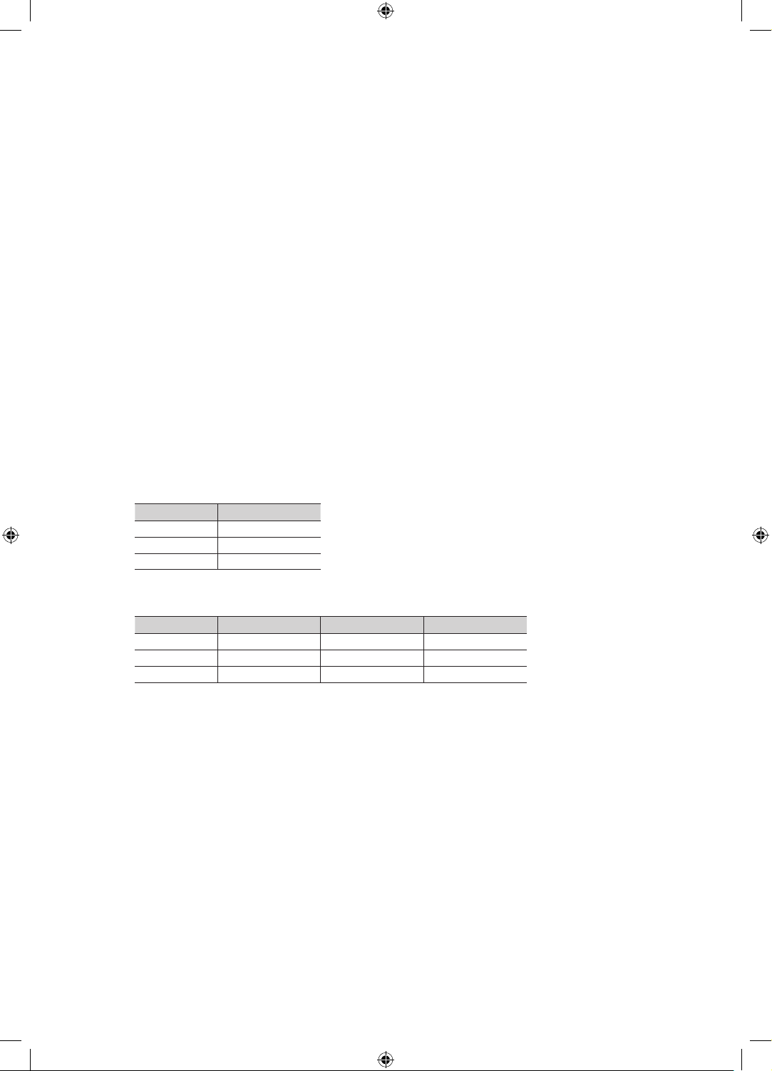
y The following table shows the approximate time in seconds it takes to switch from the TV to an input source, based on
assigned or default priorities.
✎
Scenario 1 : When no inputs are connected.
Source To Connect
AV 2 Sec
PC 0.7 Sec
HDMI 3.9 Sec
✎
Scenario 2: When two or more inputs are connected to the RJP and one of the input sources is disconnected and
then reconnected.
Source Disconnect To Connect Total
AV 4.5 Sec 2 Sec 6.5 Sec
PC 0.7 Sec 0.7 Sec 1.4 Sec
HDMI 3.9 Sec 3.9 Sec 7.8 Sec
✎
An example: If the RJP has all its live sources (AV, PC, and HDMI) connected, AV has been assigned the highest
priority, the RJP is in HDMI mode, and a guest removes and reconnects the AV source, the minimum time required
to switch to the AV source is 6.5 seconds.
y To play audio devices (Ipods, MP3 devices, etc.) through the RJP, you must turn Music Mode AV in the menu on. (See
page 19)
y Music mode in the TA-7610 RJP is supported by the AV jack only. HDMI Music mode is available for the Guestlink RJP
only.
16
[HG670677-ZA]Install Guide-ENG.indd 16 2013-02-25 �� 2:19:21
 Loading...