

Samsung hcr4755w service manual
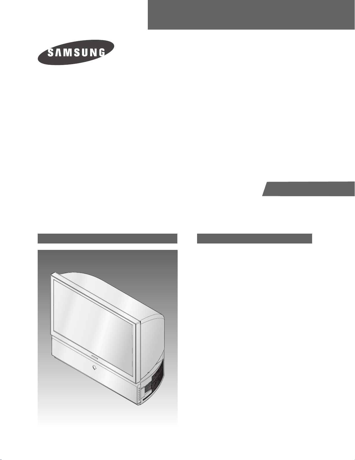
PROJECTION TV RECEIVER
Chassis : P62A(N)_Benhur-3
Model : HCR4755WX/XAA (HC-R4755W)
PROJECTION TV RECEIVER CONTENTS
1.
2.
3.
4.
5.
6.
7.
8.
Product Specification
Alignment & Adjustment
Troubleshooting
Exploded View & Part List
Electrical Part List
Block Diagram
PCB Diagram
Schematic Diagram
SERVICE
Manual
This Service Manual is a property of Samsung Electronics Co.,Ltd.
Any unauthorized use of Manual can be punished under applicable
International and/or domestic law.
© Samsung Electronics Co., Ltd. May. 2005
Printed in Korea
AA82-02523A
ELECTRONICS
Product Specification
Samsung Electronics 1-1
1. Product Specification
Model HC-R4245W HC-R4745W HC-R5245W
Voltage AC 120V AC 120V AC 120V
Frequency of Operation 60Hz 60Hz 60Hz
Power Consumption 240 watts 240 watts 240 watts
Dimensions
(W x D x H)
1004 x 500 x 967 mm
39.5 x 19.7 x 38.1 inches
1126 x 621 x 984 mm
44.3 x 24.4 x 38.7 inches
1226 x 598 x 1276 mm
48.3 x 23.5 x 50.2 inches
Weight 40.4 Kg / 89.1 lbs 49.9 Kg / 110.0 lbs 61.0 Kg / 134.4 lbs
Model HC-R4355W HC-R4755W
Voltage AC 120V AC 120V
Frequency of Operation 60Hz 60Hz
Power Consumption 240 watts 240 watts
Dimensions
(W x D x H)
1035 x 510 x 888 mm
40.7 x 20.0 x 34.9 inches
1120 x 555 x 939 mm
44.0 x 21.8x 36.9 inches
Weight 36.4 Kg / 80.2 lbs 39.5 Kg / 87.0 lbs

1-2 Samsung Electronics
MEMO
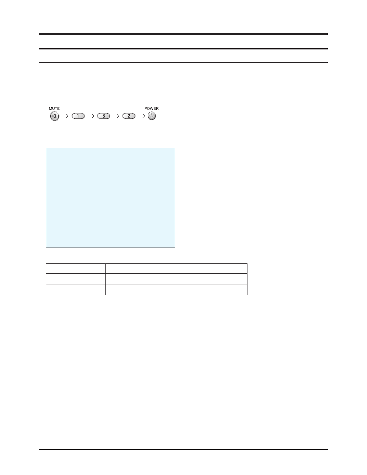
1. Turn on the TV, and then select "STANDARD" on the picture adjustment mode.
2. Turn off the TV (STAND-BY).
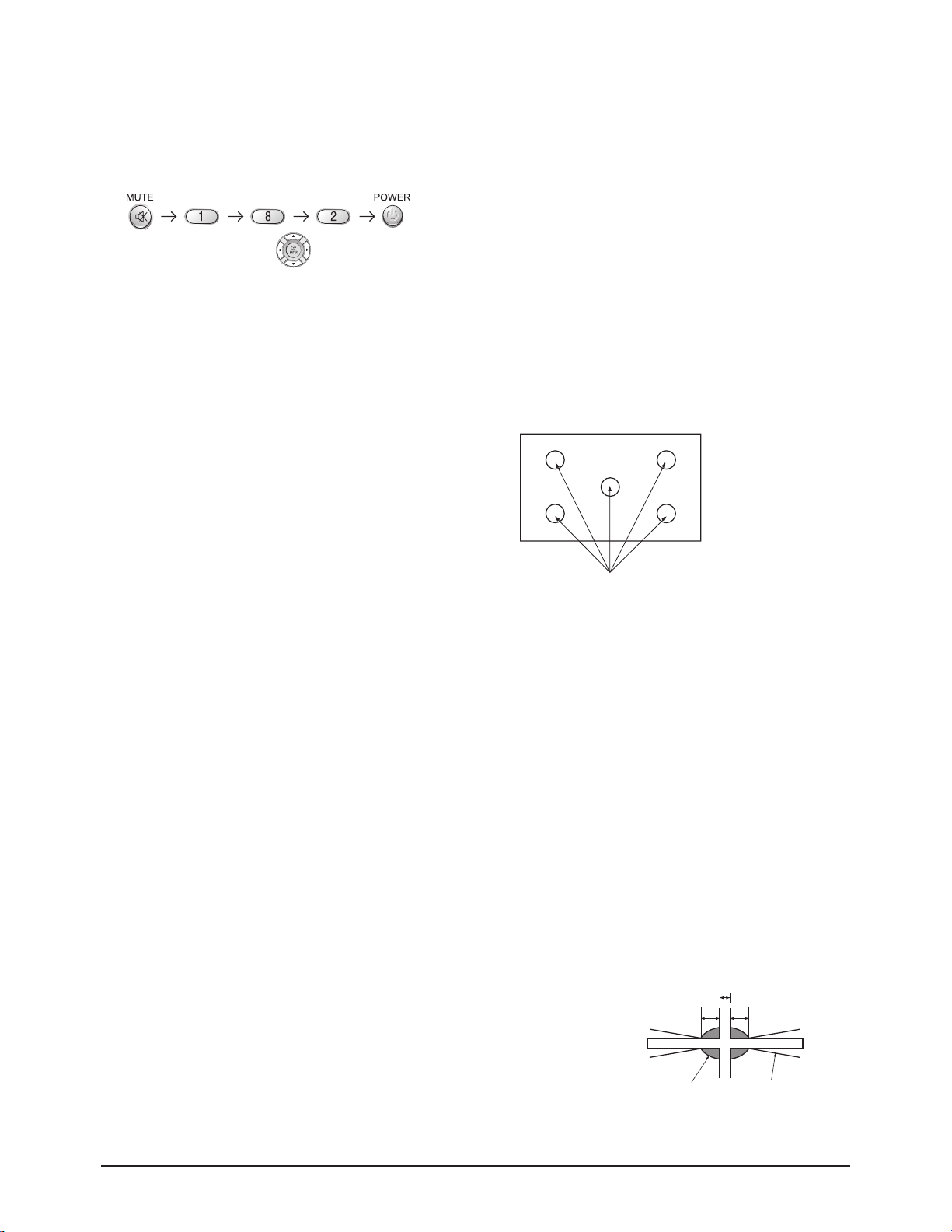
3. Enter the service mode by pressing the remote control keys in the following sequence :
Note : If necessary, re-do steps 1~3.
4. Initial SERVICE MODE DISPLAY State
5. Service Mode Control Keys
MENU Full Menu Display / Move to Parent Menu
Direction keys ▲ / ▼
Item Selection by Moving the Cursor
Direction keys ◀ / ▶
Data Increase/Decrease for the Selected Item
Alignment & Adjustment
Samsung Electronics 2-1
2. Alignment & Adjustment
2-1 When entering the service mode:
DEFLECTION
VIDEO ADJUST 1
VIDEO ADJUST 2
VIDEO ADJUST 3
VIDEO ADJUST 4
VIDEO ADJUST 5
VIDEO ADJUST 6
VERSION INFORMATION
OPTION
RESET

Alignment & Adjustment
2-2 Samsung Electronics
2-2 Factory Data
+ DVI connection item is corresponded to DVI application model.
(HCR4245W)
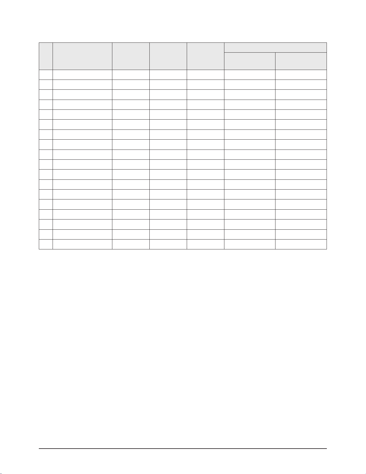
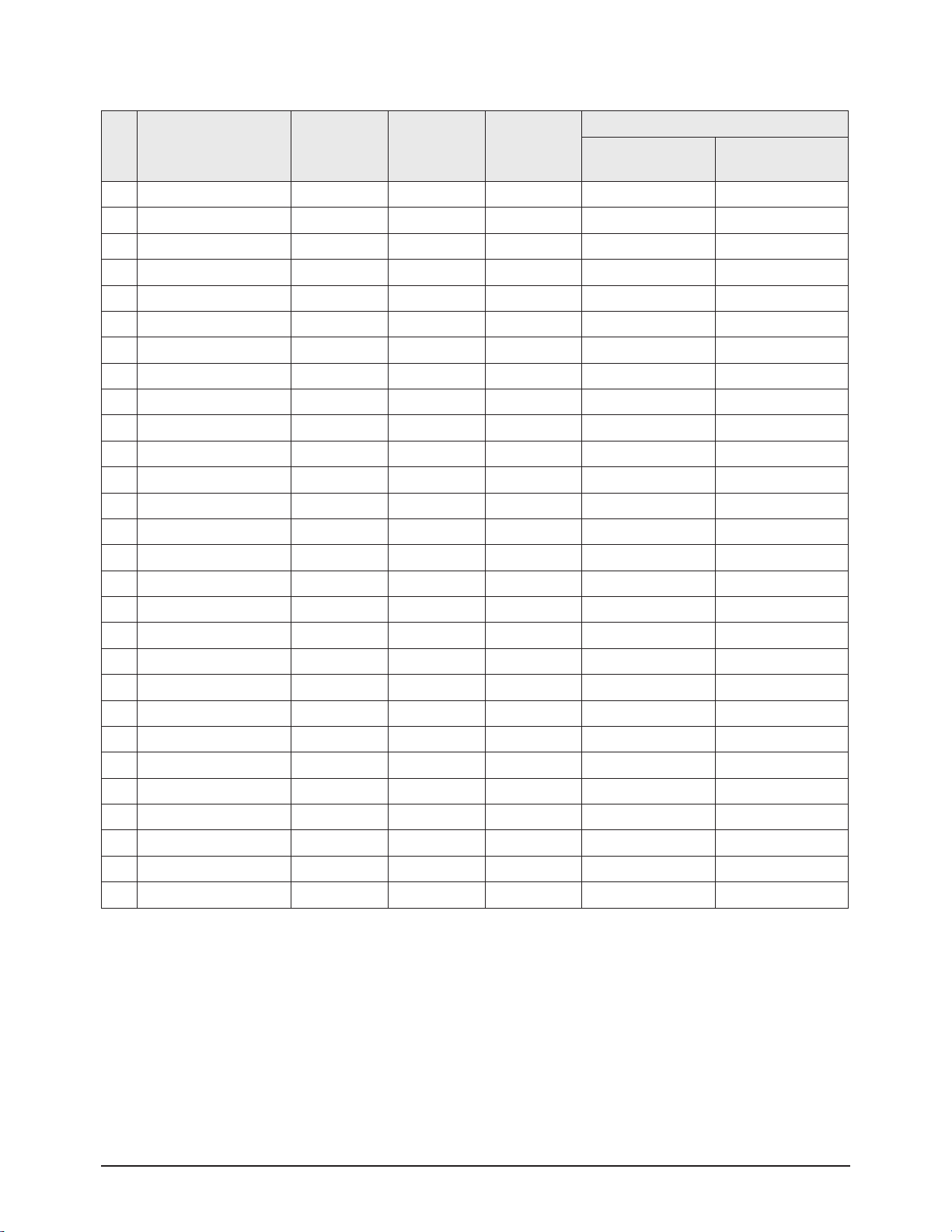
1. Deflection
No Item Initial Data Var/Fix Range
Adjust Data
All Mode
1 V Amp 31 Var 0 ~ 63 31
2 V Shift 32 Fix 0 ~ 63 32
3 H EW 31 Var 0 ~ 63 31
4 H Shift 34 Fix 0 ~ 63 34
5 V LIN 7 Fix 0 ~ 15 7
6 Up_ Lin 0 Fix 0 ~ 15 0
7 Low_Low 0 Fix 0 ~ 15 0
8 V SC 7 Fix 0 ~ 15 7
9 H Par 20 Fix 0 ~ 63 20
10 Up_ Cor 31 Fix 0 ~ 63 31
11 Low_ Cor 31 Fix 0 ~ 63 31
12 H Tra 31 Fix 0 ~ 63 31
13 Bow 31 Fix 0 ~ 63 31
14 Angle 31 Fix 0 ~ 63 31
15 V Position 31 Fix 0 ~ 63 31
16 Up UCG 0 Fix 0 ~ 3 0
17 Lo UCG 0 Fix 0 ~ 3 0
18 CXA Left Blk 55 Fix 0 ~ 63 55
19 CXA Right Blk 15 Fix 0 ~ 63 15
Alignment & Adjustment
Samsung Electronics 2-3
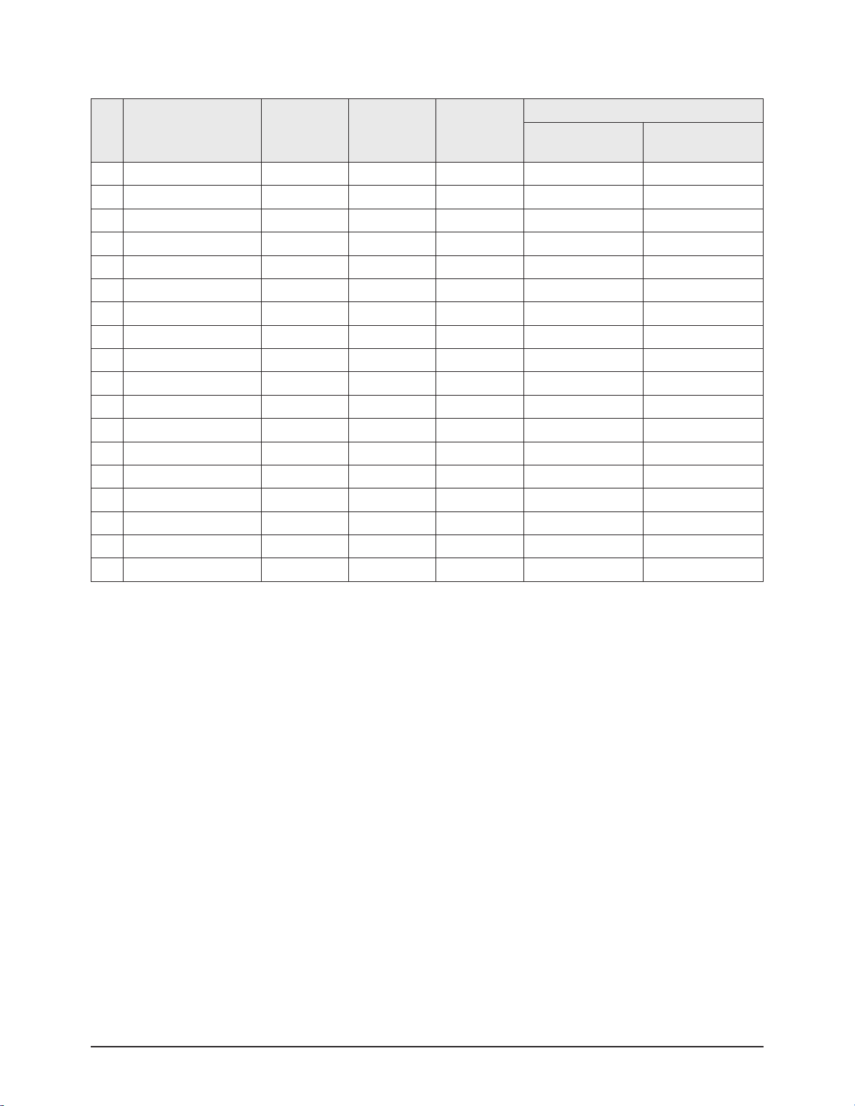
2. Video Adjust 1
No Item Initial Data Var/Fix Range
Adjust Data
DTV/480p/
720p/1080i
NT(Analog)/VIDEO
SVIDEO/480i
1 RED Cutoff 25 Var 0 ~ 63 25 25
2 GREEN Cutoff 25 Var 0 ~ 63 25 25
3 BLUE Cutoff 25 Var 0 ~ 63 25 25
4 Color On/Off 1 Fix 0/1 1 1
5 CR Offset 32 Var 0 ~ 63 32 32
6 CB Offset 32 Va r 0 ~ 63 32 32
7 RED Drive 35 Var 0 ~ 63 35 35
8 GREEN Drive 35 Var 0 ~ 63 35 35
9 BLUE Drive 35 Va r 0 ~ 63 35 35
10 Sub Bright 20 Var 0 ~ 63 20 20
11 Sub Contrast 8 Var 0 ~ 15 8 8
12 Sub Color 10 Fix 0 ~ 23 6 10 / 15 / 15 / 10
13 Sub Tint 6 Fix 0 ~ 63 6 6 / 5 / 5 / 5
14 CTI Level 1 Fix 0 ~ 3 1 1
15 COL Axis 2 Fix 0 ~ 3 2 2
16 LTI Level 1 Fix 0 ~ 3 1 1
17 LTI Mode 1 Fix 0 ~ 3 1 1
18 System 2 Fix 0 ~ 3 2 2
Alignment & Adjustment
2-4 Samsung Electronics
3. Video Adjust 2
No Item Initial Data Var/Fix Range
Adjust Data
DTV/480p/
720p/1080i
NT(Analog)/VIDEO
SVIDEO/480i
1 ABL Mode 3 Fix 0 ~ 3 3 3
2 Gamma 1 Fix 0 ~ 3 1 1
3 DPIC Level 2 Fix 0 ~ 3 2 2
4 DC Trans 2 Fix 0 ~ 3 2 2
5 ABL TH 15 Fix 0 ~ 15 15 15
6 VM Level 2 Fix 0 ~ 3 2 2
7 VM Coring 0 Fix 0 ~ 3 0 0
8 VM f0 2 Fix 0 ~ 3 2 2
9 VM Limit 3 Fix 0 ~ 3 3 3
10 VM Delay 0 Fix 0 ~ 3 0 0
11 SHP CD Gain 1 Fix 0 ~ 3 1 1
12 SHP f0 0 Fix 0/1 0 0
13 SHP f1 Gain 3 Fix 0 ~ 3 3 3
14 Pre/Over 1 Fix 0 ~ 3 2 1
15 AKB Timing 11 Fix 0 ~ 32 11 11
16 S ABL 3 Fix 0 ~ 3 0 0
17 P ABL 10 Fix 0 ~ 15 10 10
18 Picture Limit 3 Fix 0 ~ 3 3 3
Alignment & Adjustment
Samsung Electronics 2-5
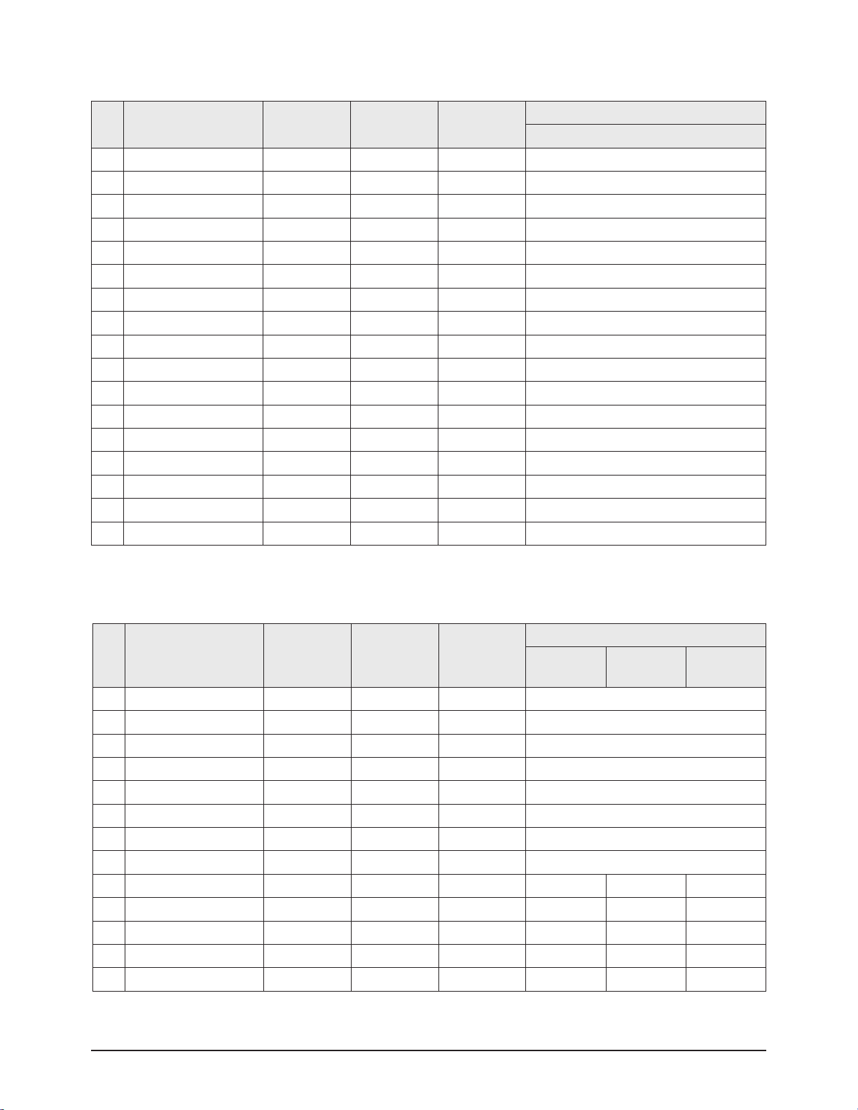
4. Video Adjust 3
No Item Initial Data Var/Fix Range
Adjust Data
All Mode
1 H Comp 12 Fix 0 ~ 15 12
2 V Comp 8 Fix 0 ~ 15 8
3 Pin Comp 0 Fix 0 ~ 7 0
4 AFC Comp 0 Fix 0 ~ 7 0
5 CG HAO 5 Fix 0 ~ 20 5
6 CG VAO 5 Fix 0 ~ 20 5
7 BKG Level 25 Fix 0 ~ 63 25
8 CM THRESHOLD 42 Fix 20 ~ 80 42
9 CM Det Time 0 Fix 0.5sec/1step 0
10 Pixel_shift_Time 60 Fix 0/5/30/60 60
11 H_Peaking 2 Fix 0 ~ 7 2
12 PFS 2 Fix 0 ~ 3 2
13 LPF 2 1 Fix 0 ~ 3 1
14 PKCOR 0 Fix 0 /1 0
15 CKILL 2 Fix 0 ~ 15 8(2)
16 AFT On/Off 1 Fix 0/1 1
17 Melody Volume 10 Fix 0 ~ 20 10
5. Video Adjust 4
No Item Initial Data Var/Fix Range
Adjust Data
480p other
720p
(Component)
1080i
(Component)
1 YC RF Delay 1 Fix 0~31 1
2 YC AV Delay 5 Fix 0~31 5
3 Chroma Band RF 0 Fix 0 ~ 63 0
4 Chroma Band Video 0 Fix 0 ~ 63 0
5 Chroma Band SVideo 1 Fix 0 ~ 63 1
6 IF Comp 2 Fix 0 ~ 4 2
7 IF Comp Video 4 Fix 0 ~ 4 4
8 IF Comp SVideo 4 Fix 0 ~ 4 4
9 9883 RED CUTOFF 128 Fix 0 ~ 255 123 122 122
10 9883 GREEN CUTOFF 128 Fix 0 ~ 255 105 105 99
11 9883 BLUE CUTOFF 128 Fix 0 ~ 255 123 124 124
12 9883 Phase 88 Fix 0 ~ 255 88 176 176
13 9883 Sync Level 50 Fix 0 ~ 255 50 32 32
Alignment & Adjustment
2-6 Samsung Electronics
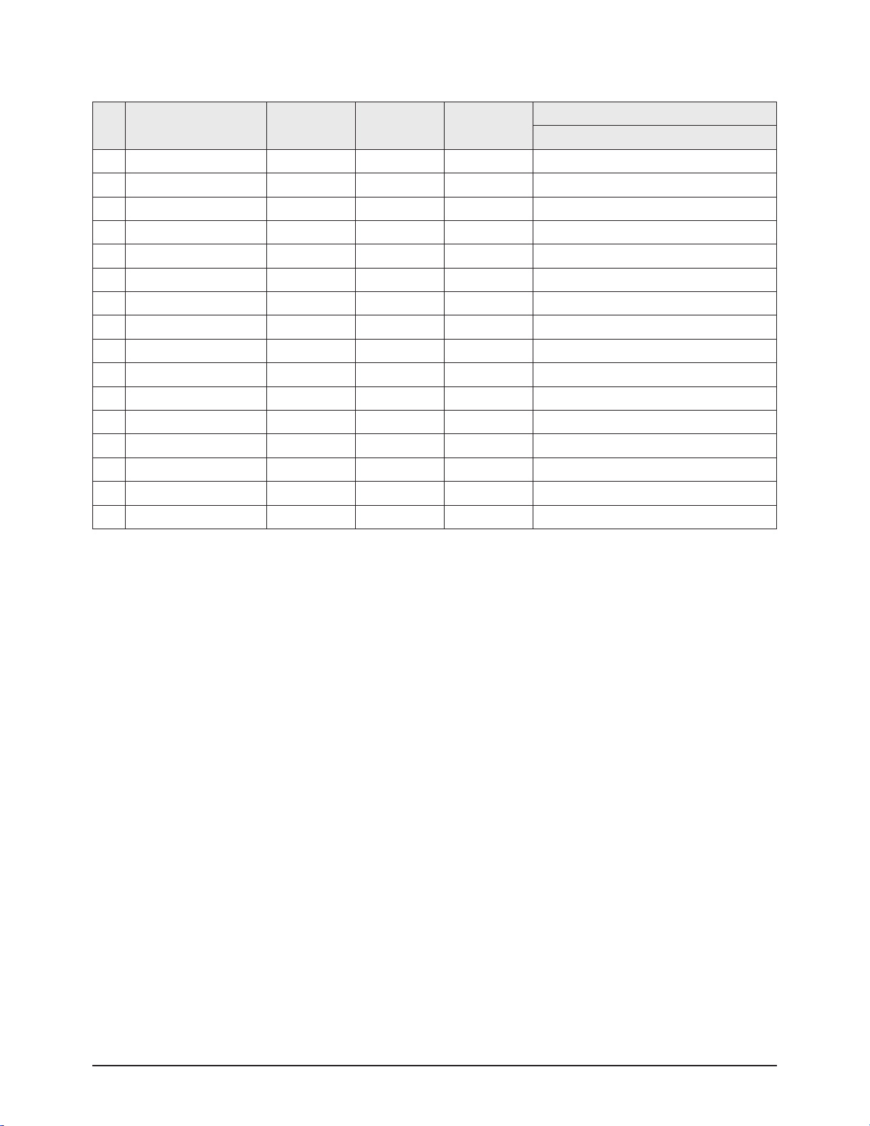
6. Video Adjust 5
No Item Initial Data Var/Fix Range
Adjust Data
NT(Analog)
1 BASE LEVEL Read Fix
2 RFDB1_H_PEAKING 0 Fix 0
3 RFDB1_LPF2 1 Fix 1
4 RFDB1_PKCOR 0 Fix 0
5 RFDB1_SHARPNESS 75 Fix 75
6 RFDB2_H_PEAKING 0 Fix 0
7 RFDB2_LPF2 1 Fix 1
8 RFDB2_PKCOR 1 Fix 1
9 RFDB2_SHARPNESS 50 Fix 50
10 RFDB3_H_PEAKING 0 Fix 0
11 RFDB3_LPF2 2 Fix 2
12 RFDB3_PKCOR 1 Fix 1
13 RFDB3_SHARPNESS 20 Fix 20
14 RFDB1_VALUE 112 Fix 112
15 RFDB2_VALUE 200 Fix 200
16 RFDB3_VALUE 500 Fix 500
Alignment & Adjustment
Samsung Electronics 2-7
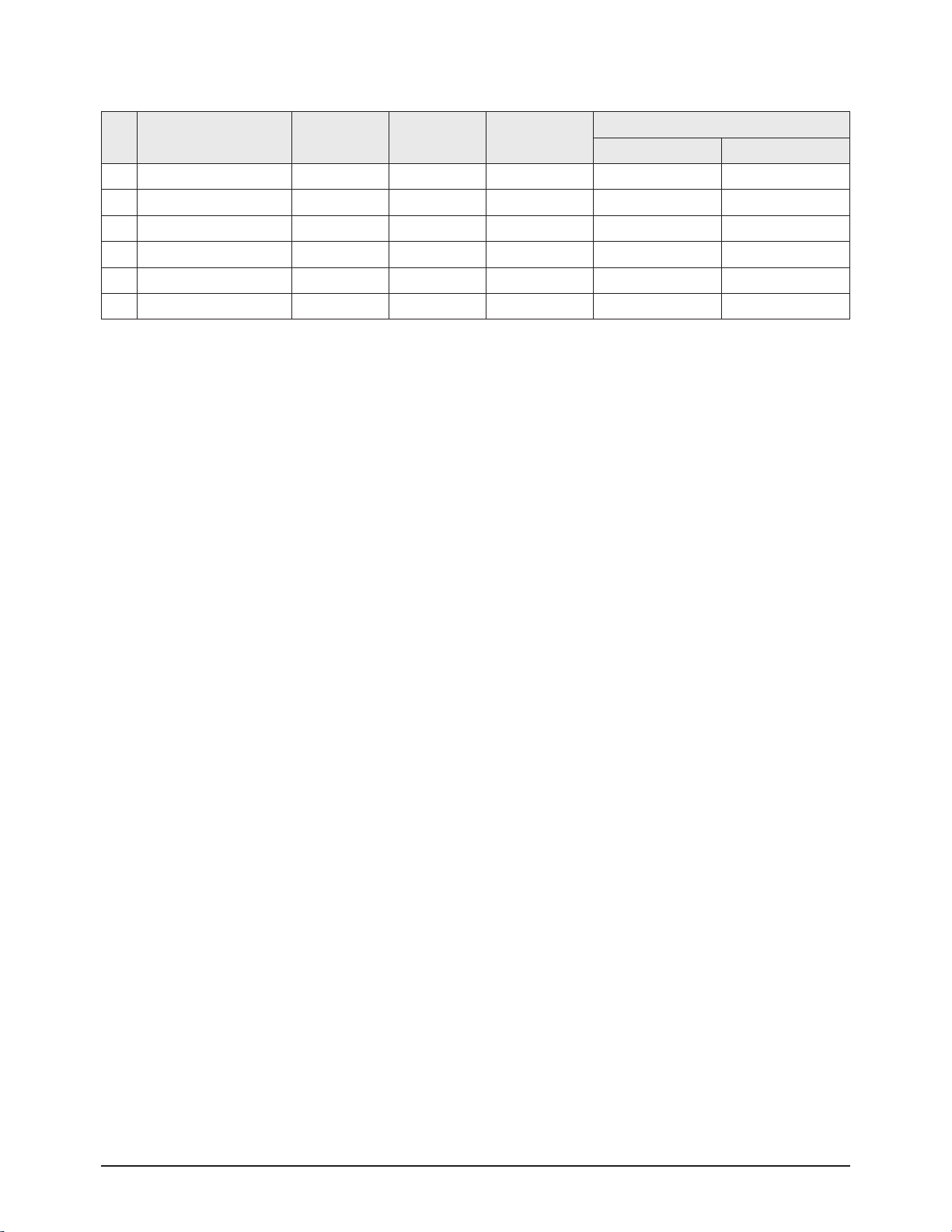
7. Video Adjust 6
No Item Initial Data Var/Fix Range
Adjust Data
DTV/480p/
720p/1080i
NT(Analog)/VIDEO
SVIDEO/480i
1 ALPHAL 128 Fix 0 ~ 255 128 128
2 ALPHAU 128 Fix 0 ~ 255 128 128
3 CE_CUTOFF 32 Fix 0 ~ 255 32 32
4 CE_UPPER 220 Fix 0 ~ 255 220 220
5 CE GainMax L 160 Fix 0 ~ 255 160 160
6 CE GainMax U 160 Fix 0 ~ 255 160 160
7 GAIN1X 16 Fix 0 ~ 63 16 16
8 GAIN1Y 8 Fix 0 ~ 63 8 8
9 GAIN2X 8 Fix 0 ~ 63 8 8
10 GAIN2Y 4 Fix 0 ~ 63 4 4
11 GAIN3X 1 Fix 0 ~ 63 1 1
12 CORING_ON 1 Fix 0 ~ 1 1 1
13 CORING_TH1 2 Fix 0 ~ 7 2 2
14 CORING_TH2 1 Fix 0 ~ 7 1 1
15 CORING_TH3 1 Fix 0 ~ 7 1 1
16 SD3_K 8 Fix 0 ~ 255 8 8
17 Skin_X 24 Fix 0 ~ 63 24 24
18 Skin_Y 29 Fix 0 ~ 63 29 29
19 SCALE_R 75 Fix 0 ~ 255 75 75
20 SCALE_ALPHA 140 Fix 0 ~ 255 140 140
21 Gamma On 0 Fix 0 ~ 7 0 0
22 Dither Mode 0 Fix 0 ~ 7 0 0
23 NDON 1 Fix 0 ~ 1 1 1
24 NEOnDE 1 Fix 0 ~ 1 1 1
25 NEOnCE 1 Fix 0 ~ 1 1 1
26 RTH2 10 Fix 0 ~ 15 10 10
27 Sub_Contrast 128 Fix 0 ~ 255 128 128
28 Sub_Brightness 0 Fix 0 ~ 255 0 0
Alignment & Adjustment
2-8 Samsung Electronics
8. Option
No Item Initial Data Var/Fix Range
Adjust Data
Korea America
1 Anynet Enable On Va r On/Off On On
2 DNIe Off Var On/OFF/Demo Demo Off
3 Panel Key Enter Var Enter/Mute Enter Enter
4 LNA On Var On/Off On Off
5 DVI Off Va r On/Off Off On
6 V-CHIP USA Var Off/USA/USA+C Off USA
Alignment & Adjustment
Samsung Electronics 2-9
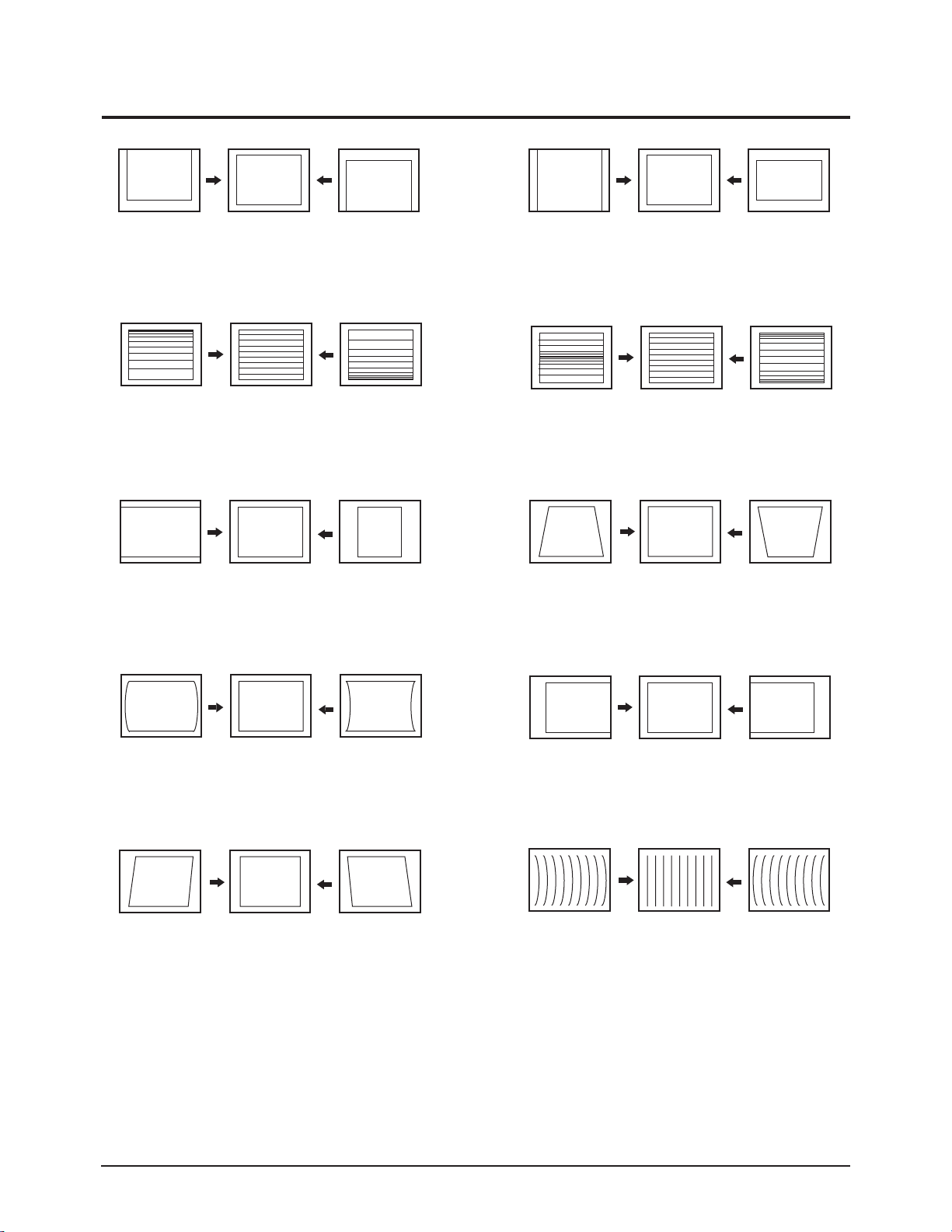
2-3 Screen Change (When adjusting I2C Bus Geometric items)
6
1 V SHIFT
2
V LINEARITY
3
H SIZE
V SIZE
7
V - S - CORRECTION
8
PIN PHASE
4
5
PIN AMP
V ANGLE
9
10
H SHIFT
V BOW
Alignment & Adjustment
2-10 Samsung Electronics
2-4 Other Adjustments
2-4-1 Screen Adjustment
1. Warm up the TV for at least 30 minutes.
2. Select the "STANDARD" Video Mode.
3. Turn to the Video Mode (No Signal) using a remote-control.
4. Connect an oscilloscope to RK,GK,BK.
5. Adjust the VR Screen (in the Focus Pack) to have 20VP-P for the RK, GK and BK pulse.
(Turn the R, G and B VR screen fully counterclockwise at each flyback line.)
※ Voltage adjustment connt be done using a normal multi-tester. For adjustment, use an oscilloscope.
The voltage shown by the tester is false data because the AC peak to peak voltage is adjusted under DC
conditions.
2-4-2 White Balance Adjustment
1. Select the "STANDARD" Video Mode.
2. Input 100% white pattern.
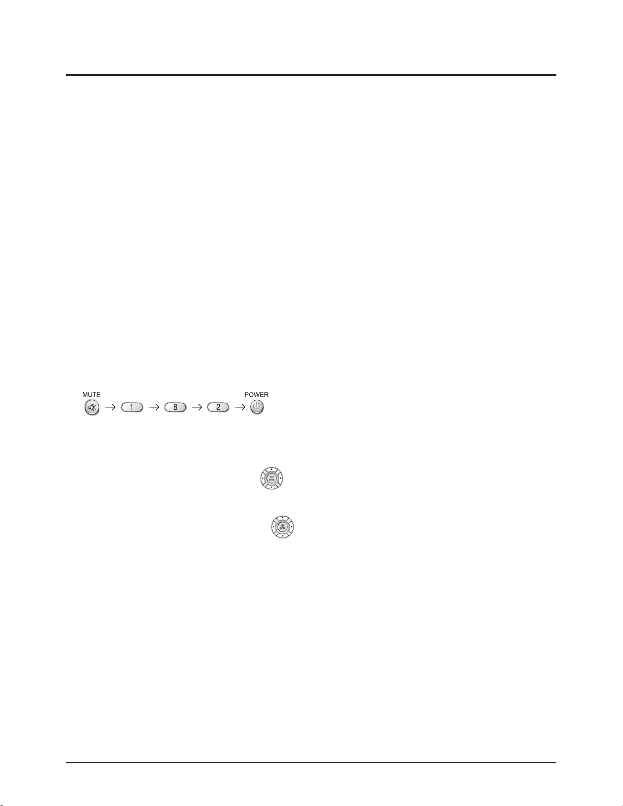
3. In the stand-by mode, press the remote-control keys in the following sequence:
4. Warm up the TV for at least 30 minutes.
5. Input a 10-step signal.
6. R-cut off, B-cut off, and G-cut off by pressing the keys.
7. Adjust the low light with viewing the dark side of the screen.
8. Select R-drive, G-drive, and B-drive by pressing the keys.
9. Adjust the high light with viewing the light side of the screen.
10. If necessary, redo screen adjustments and 6~9.
11. Press the Add key to exit.
Alignment & Adjustment
Samsung Electronics 2-11
2-4-3 Sub-Brightness Adjustment
1. Input a sub-brightness adjustment signal. (TOSHIBA PATTERN)
2. In the stand-by mode, press the remote-control keys in the following sequence :
3. Select SBT by pressing the keys.
4. Adjust so that the 63 step on the right side of the screen is not seen (Use the keys).
5. Press the Menu key to exit.
2-4-4 Static Focus Adjustment
Precaution
1. Select the "STANDARD" video mode.
2. Input a crosshatch pattern.
3. Cover the lenses that are not being adjusted.
4. Connect a convergence jig and read data.
5. Adjust the lens for best focus. (See Fig, 2-1)
Static Focus (continued)
Vary the focus pack VR (Red, Blue) on the front cabinet. Adjust the TV for best possible focus around the center of the
crosshatch pattern, without losing overall screen balance. Figure Crosshatch Pattern Examine these points together.
2-4-5 Lens Focus Adjustment
1. Preparation
① Set the Screen to "STANDARD". (Contrast : 100 / Brightness : 50)
② Set the pattern to Crosshatch.
③ Adjust the electric focus before beginning.
④ Adjust the DY tilt (TILT) before beginning.
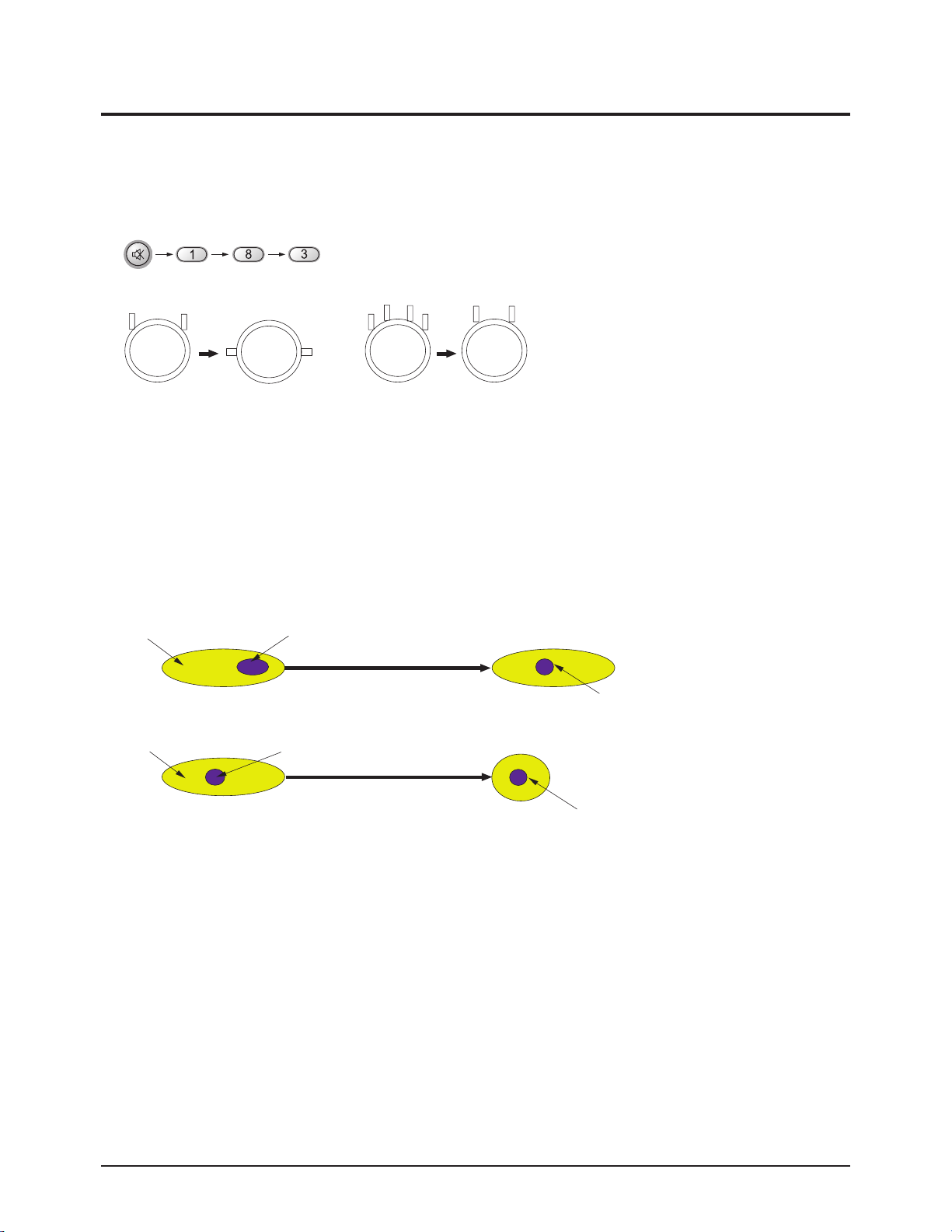
2. How to Adjust (Green Lens Adjustment)
① Loosen the lens screw for easier adjustment.
② Press Mute, 1, 8 and 3, sequentially to enter Convergence Mode.
③ Display only the Green pattern by using the +100, 0, and Previous Channel Keys in order to turn the R, G, and B patterns
On/Off respectively.
④ Turn the Green Lens clockwise/Counterclockwise to adjust for optimum status.
(Repeat if unsuccessful, varying the VR of the front Focus Pack.)
⑤ Perform steps 1~3 for the R and B Lenses.
3. Note
Green determines picture quality; pay close attention for exact adjustment.
Examine these points together
Fig. 2-1 Crosshatch Pattern.
Red Chromatic Number
Blue Chromatic Number
P
L1
L2
<_
L1, L2 P
Fig. 2-2 Color Aberration
Alignment & Adjustment
2-12 Samsung Electronics
2-5 Beam Alignment Adjustments
1. Select the "STANDARD" Video Mode.
2. Warm up the set at least for 10 minutes.
3. Enter the Convergence mode by pressing the remote control buttons in the following sequence.
4. Set the Beam Alignment Adjustment CY to Zero magnetic field area.
5. Press the 7- digit button for a while, on the remote control, and a vibrating dot-pattern appears.
6. Adjust the Focus-pack VR for defocusing.
7. Mute the other patterns (R/B) other than G-PATTERN. (Use "+100" / "PRE-CH" Key on the remote control.)
8. Adjust the 2, 4 polarities of VM-COIL as shown in figure below.
9. Adjust the G-Focus until any light around the core disappears.
10. Adjust G-Focus so that the surrounding flash can disappear from the spot.
11. After G-Focus adjustments are complete, adjust R-Focus as above procedures.
12. The B-CRT adjustments can be omitted because the variance of beam focus is small. (Only Vm-coil is mounted.)
13. Adjust the Focus-pack VR for fine focusing.
14. Press the 7- digit button for a while, on the remote control, and the mode changes to the Convergence Adjustment mode.
15. Press the "S.MODE" Key on the remote control to return to normal viewing.
G-FOCUS
CORE
CORE
G-FOCUS
c
MUTE
(Creation of CPM Zero Magnet) (Creation of the 2-pole/4-pole zero magnets)
G-FOCUS
(Varying G-Focus Pack)
G-FOCUS
(When VM 2-Pole Adjustment is completed) (Adjust until the light around the core becomes a
CORE
Varying the 2-pole of
(Positioning the Core in the Center)
CORE
Varying the 4-pole of VM
Alignment & Adjustment
Samsung Electronics 2-13
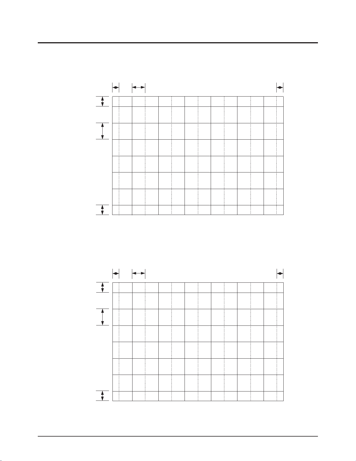
2-6 Convergence-Jig
2-6-1 4245W RF Mode
2-6-2 4245W DTV Mode
Screen Size : X 925, Y 523 (X: 378 =9*2 + 30*12 , Y:440=28* 2+64* 6)
22.02mm 73.41mm
33.28mm
76.07mm
33.28mm
22.02mm
42.87mm
72.88mm
42.87mm
Screen Size : X 925, Y 523 (X: 396 =12*2 + 31* 12, Y : 488= 40* 2+68* 6)
28.03mm 72.41mm
28.03mm
Alignment & Adjustment
2-14 Samsung Electronics
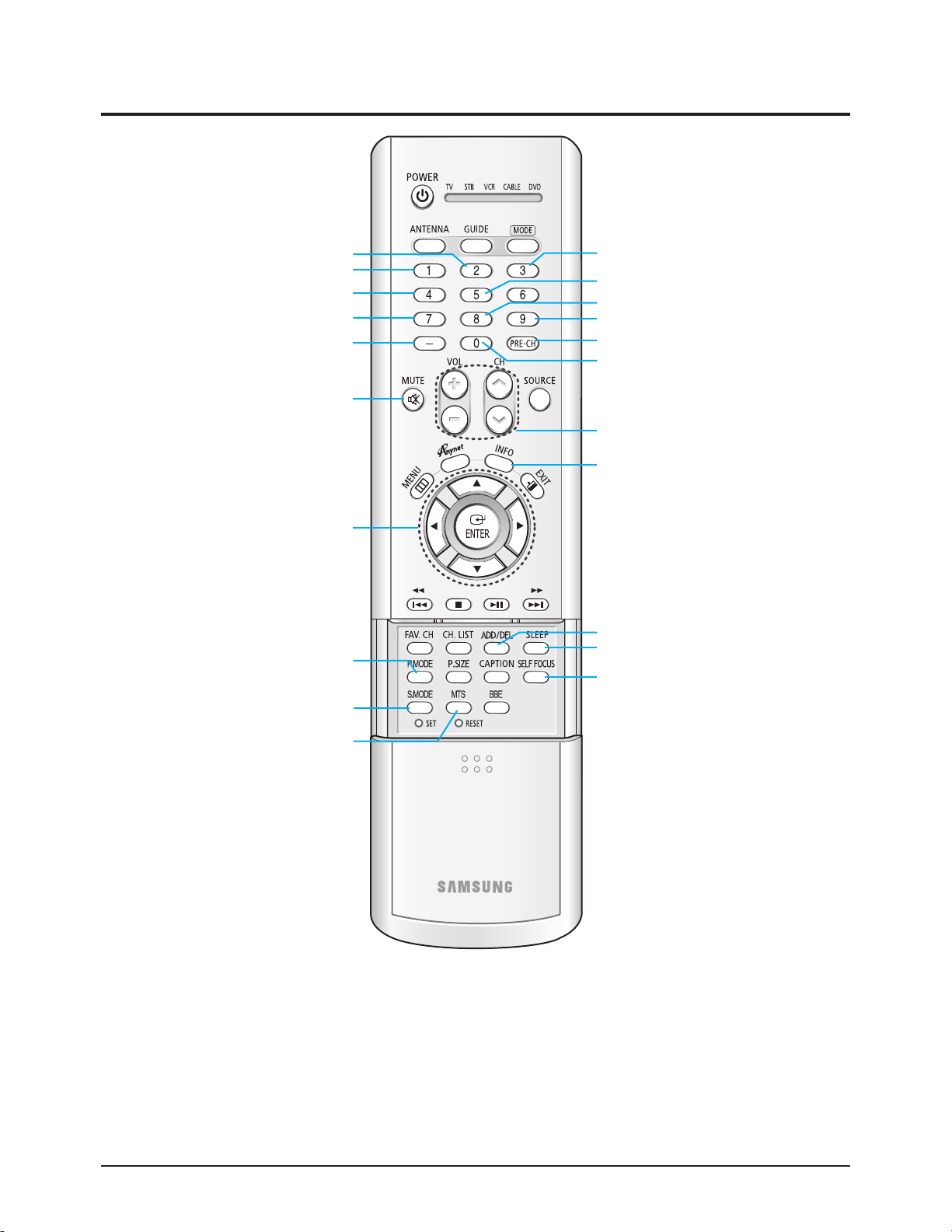
2-7 Remote Control Key Functions in Convergence Mode
Recalls the previous data before convergence adjustment
(Initializes)
Sets Convergence Data to 0
Normal/Line Shif
Adjustment Pattern Select Button (Red)
Red Convergence Pattern ON/OFF
*Moves the Cursor
(Backwards: Right or Down)
*Moves the Cursor
(: Left, Right or Up, Down)
*Moves the Cursor
(Backwards: Left or Up)
Exit the Convergence Mode and switch to RF mode
Moves the Convergence Pattern to the left
Recovers previous data settings during Convergence
Adjustment or recalls the last memorized data
Data Initialize key for each screen size
Adjustment Pattern Select Button (Green)
Adjustment Pattern Select Button (Blue)
Blue Convergence Pattern ON/OFF
Green Convergence Pattern ON/OFF
Convergence Adjust Button (Left/Right) (Up/Down)
Toggles between the Convergence
Adjustment screen and the RF screen
Save data after completing Convergence Adjustment
Moves the Convergence Pattern to the right
Automatic Convergence Adjustment
after completing Convergence Adjustments
(Automatic Color Adjustment to
compensate for the earth s magnetic field.)

Alignment & Adjustment
Samsung Electronics 2-15
2-8 Pin Assign
2-8-1 Micom Block
Pin # Pin Assign Pin # Pin Assign
1 WP 52 POWER
2 SCL-E2PROM 51 MICOM-D6
3 SDA-E2PROM 50 MICOM-D5
4 BUS-STOP 49 MICOM-D4
5 SDA-MICOM 48 MICOM-D3
6 SCL-MICOM 47 MICOM-D2
7 N.C 46 MICOM-D1
8 N.C 45 MICOM-D0
9 VDD 2.5V 44 VDD 3.3V
10 GND 43 GND
11 VDD 3.3V 42 VDD 2.5V
12 CAPTION-CVBS 41 N.C
13 VDDA 2.5V 40 N.C
14 GND 39 N.C
15 N.C 38 N.C
16 N.C 37 VDDA 2.5V
17 KEY2 36 GND
18 KEY1 35 XTAL-OUT
19 HSYNC 34 XTAL-IN
20 VSYNC 33 RESET
21 KEY3 32 N.C
22 5V-INT 31 N.C
23 PROTECT 30 VDD 3.3V
24 IR 29 GND
25 STB-LED 28 MICOM-INT
26 TIMER-LED 27 CPU-nRESET
Alignment & Adjustment
2-16 Samsung Electronics
2-8-2 Convergence Module
CN01
PIN NAME PIN PIN PIN NAME
N.C 1 32 GND
GND 2 31 5V
Dynamic-Fcous 3 30 -5V
GND 4 29 N.C
D2(SCL) 5 28 GND
D1 6 27 V-BLK
GND 7 26 H-BLK
C-SYNC 8 25 GND
R 9 24 RH
G 10 23 RV
B 11 22 GH
D3(SDA) 12 21 GV
N.C 13 20 BH
IR 14 19 BV
F-BLK 15 18 GND
GND 16 17 GND
CN02
PIN PIN NAME
1 GND
2 5V
3 UP
4 GND
5 5V
6 Right
7 GND
8 5V
9 Left
10 GND
11 5V
12 Down
Alignment & Adjustment
Samsung Electronics 2-17
2-8-3 DTV Module
CN100
Pin # Pin Assign Pin # Pin Assign
1 SDA-CH 25 AGC-SW
2 SCL-CH 26 BUS-STOP
3 NC 27 TS-VLD
4 NC 28 GND
5 NC 29 TS-SYNC
6 DVI-ID 30 GND
7 NC 31 TS-CLK
8 GND 32 GND
9 TS-DATA7 33 NC
10 TS-DATA6 34 NC
11 TS-DATA5 35 AMP-MUTE
12 TS-DATA4 36 CPU-nRESET
13 TS-DATA3 37 S-RESET
14 TS-DATA2 38 NC
15 TS-DATA1 39 12V
16 TS-DATA0 40 GND
17 GND 41 GND
18 DTV-Y 42 STB-5V
19 DTV-PB 43 STB-5V
20 DTV-PR 44 GND
21 GND 45 GND
22 DTV-HSO 46 3.3V-D
23 DTV-VSO 47 3.3V-D
24 GND 48 3.3V-D
CN101
Pin # Pin Assign Pin # Pin Assign
1 SCL-CG 25 SCL-M5
2 SDA-CG 26 SDA-M5
3 2RF-SW 27 GND
4 TU-RST 28 GND
5 GND 29 COMP2-Y
6 AUD-SDATAO 30 COMP2-PB
7 GND 31 COMP2-PR
8 AUD-SCLK 32 GND
9 AUD-LRCLK 33 NC
10 GND 34 GND
11 NC 35 MAIN-C
12 NC 36 GND
13 GND 37 MAIN-Y/C
14 COMP1-Y 38 GND
15 COMP1-PB 39 GND
16 COMP1-PR 40 DTV-CVBS
17 GND 41 GND
18 NC 42 SCL-MICOM
19 GND 43 SDA-MICOM
20 NT-SOUND-L 44 GND
21 NT-SOUND-R 45 XTAL-ON/OFF
22 VOLT-DET 46 GND
23 NC 47 5V
24 NC 48 5V
 Loading...