


SAMSUNG
R65/P50
HABANA
NP-R65xxxx/xxx
NP-P50xxxx/xxx
SERVICE
Manual
SAMSUNG R65/P50
FEATURES
1. Simple & Essential Note PC
-. New Intel Napa technology.
-. High Bright Gloss, 4:3 LCD.
-. Convenient Multi-media.
2. High Performance &
Convenient Management function.
-. High-Performance Dual Core
-. Powerful connectivity.
If there are the Contents not included in this book, please refer to K-zone Service Manual

- This Document can not be used without Samsung's authorization -
- Contents -
1. Precautions
1) General After-Sales Service Precautions
2) Safety Precautions
3) Ground
4) Static Electricity Precautions
2. Introduction and Specification
1) Introduction
2) Specification
3) Specification comparison between R50 and R65.
4) Wireless LAN Specification
5) Option list
6) The seperate sale list
3. Function
1) Construction of System
2) Keyboard
3) Multi Card Slot
4) PC Card Slot
5) SPDIF Port
6) ASF and Core Multi Processing
7) Description of Main board
4. Disassembly and Reassembly
1) Disassembly and Reassembly of R65
2) Disassembly and Reassembly of P50
5. Troubleshooting
1) General
2) Debugging Flow Chart
3) System Diagnosis
4) Hardware Troubleshooting
5) Device Settings Related Software Diagnosis
6) CPU Fan Control Problems
7) Battery Use Time
6. Exploded view
1) Exploded view of R65
2) Exploded view of P50
3) ODD
7. Schematic
1) SYSTEM
2) External GFx Board
3) Ontop Board
4) Touchpad Board

- This Document can not be used without Samsung's authorization -
- Contents -
8. System Block Diagram
1) Block diagram
9. System Wire Diagram
1) R65 Top
2) R65 Bottom
3) P50 Top
4) P50 Bottom
5) LCD
10. Part list
1) SYSTEM
2) External GFx board
11. References
1) Safety Notice
2) Model Numbering Rule
3) CPU Code table
4) Glossary
5) Hardware Upgrade

- This Document cannot be used without the authorization of Samsung -
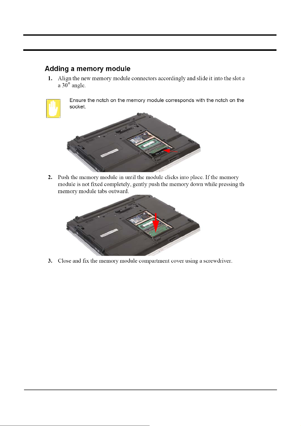
1.
Precautions
1) General After-Sales Service Precautions
(1) Do not let customers repair the product themselves.
☞
There is a danger of injury and the product life time may be shortened.
(2) Make sure to disconnect the power cord from the wall outlet before repairing the product
(especially for after-sales service of electric parts).
☞
There is a danger of electric shock.
(3) Do not let customers plug several electric home appliances into a single wall outlet at the same
time
☞
There is a danger of fire due to overheating.
(4) Check if the power plug or wall outlet are damaged in any way.
repair or replace it immediately. (There is a danger of electric shock or fire)
(5) Make sure that it is properly grounded. (Check the ground of the wall outlet)
☞
Electricity leakage may cause electric shock.
(6) Do not spray water on to the product to clean it.
☞
There is a danger of electric shock or fire and it may shorten the lifetime of the product.
(7) Check the assembly status of the product after the after-sales service.
☞
The assembly status of the product must be the same as before the after-sales service.
(8) Unplug the power cord holding the power plug (and not the cord).
☞
If the cord is disconnected, it may cause electric shock or fire.
(9) Repair the product using only authorized parts.
(10) Keep the product away from heating devices such as heaters.
☞
Exposure to heaters may cause deformation of the product or fire.
☞
If a defect is found,
1-1

- This Document cannot be used without the authorization of Samsung -
1.
Precautions
2) Safety Precautions
(1) EMI
This device has been registered regarding EMI for residential use. It can be used in all areas.
(2) Circuit Test (Logic Test) Precautions
The LSI and MSI used in this product are semiconductor integrated circuits based on MOS-FET
or CMOS. Since these types of devices are highly susceptible to static electricity or current
leakage, an isolation break may be caused. Therefore read and follow the instructions below.
1. When handling an LSI or MSI, make sure your body is grounded through a few mega-ohms
of resistance. In addition, wear gloves and a jacket made of cotton and not of synthetic fibers
that easily generate static electricity.
2. When repairing the product, place a conductive material (e.g. aluminum foil) grounded to the
earth on the worktable.
3. You must use a soldering iron without a leakage current.
4. Do not touch the pin of an IC and carefully insert the IC into the black plastic package.
5. When inserting an IC into a PCB, be careful with the direction of the IC. When installing an
IC in the wrong direction, it might become damaged.
6. When carrying an IC, package the IC with conducting material such as aluminum foil or
conducting sponge so as to keep the voltage level of each of the terminals the same.
7. Since the storage temperature of an IC is between -20 ~ +70 degrees, keep it at room
temperature, if possible.
8. When installing or removing a device from a PCB or installing or removing a board, you
must disconnect the power before taking any action.
9. When soldering an IC, solder it in as short a time as possible so that unnecessary heat is
not applied to the device.
10. Avoid leaving excessive amounts of flux within a custom IC or between the pins when soldering
acustomIC.
11.TakecaretonotdamagetheboardwheninstallingorseparatinganOptionBoard.
12. Take care to not break the printed circuit pattern on the PCB when separate an IC.
1-2

- This Document cannot be used without the authorization of Samsung -
1.
Precautions
3) Ground
The product must be grounded to protect it from static electricity and other dangers. When using a
multitap,pleaseuseamultitapwithagroundterminalonly.
If you use a 220V wall outlet with a ground terminal, you do not need to ground it additionally. Avoid
using wall outlets if they are not grounded even if they have a ground terminal.
To ground the product, connect the ground to an exclusive ground terminal or metal water pipe.
Connect the ground cable to the ground terminal at the rear of the main body. To ground the product,
connect the ground terminal of the product to a metal water pipe, wall outlet or exclusive ground terminal
with an electric wire equal to or thicker than #18.
Never ground the product to a PVC water pipe, phone line, TV, radio antenna, aluminum window or
gas pipe, because this does not actually ground the product and may be dangerous.
4) Static Electricity Precautions
Many parts of the system are susceptible to static electricity. Using an electrostatic discharge (ESD)
device is very important for the safety of the user and the user's surroundings. Using an ESD device
increases the probability of a successful repair and lowers the expenses for damaged parts.
To prevent static electricity, follow the instructions below.
(1) Perform the repair in a location without static electricity.
(2) Touch your hands to a metal water pipe or some metal object connected to the ground to
discharge any static electricity from your body before handling the parts.
(3) Touch only the edges of the board, if possible.
(4) Do not touch any parts unless absolutely necessary
(5) Disassemble the parts on the anti-static-electricity pad.
(6) When a board is not installed in the system, packagetheboardwithananti-static-electricity
packaging.
1-3

- This Document can not be used without Samsung's authorization -
11. References
1) Safety Notice
(1) An electric leakage related safety
Electric leakage is the flow of electricity to the ground through electrical wires due to ripped coating or bad
insulation. Electric leakage can cause electric shock or fire, which in turn may lead to casualties and loss. It
can also result in excessive electric charges.
(2) An electric leakage prevention
- Do not separate or disassemble the system even though system is shut down in a AC power supplies.
In that situation, system could be damaged.
- The electricity could be generated in winter or a dry space, prepare the leakage prevention for the
electricity when you try to disassemble.
- Do not use in strong magnetic space.
- Use the proper adapter and battery.
- Insertion of including saline could cause the leakage.
If you don't keep those things, there is a danger of electric shock, system damage and so on.
11-1
- This Document can not be used without Samsung's authorization -
11. References
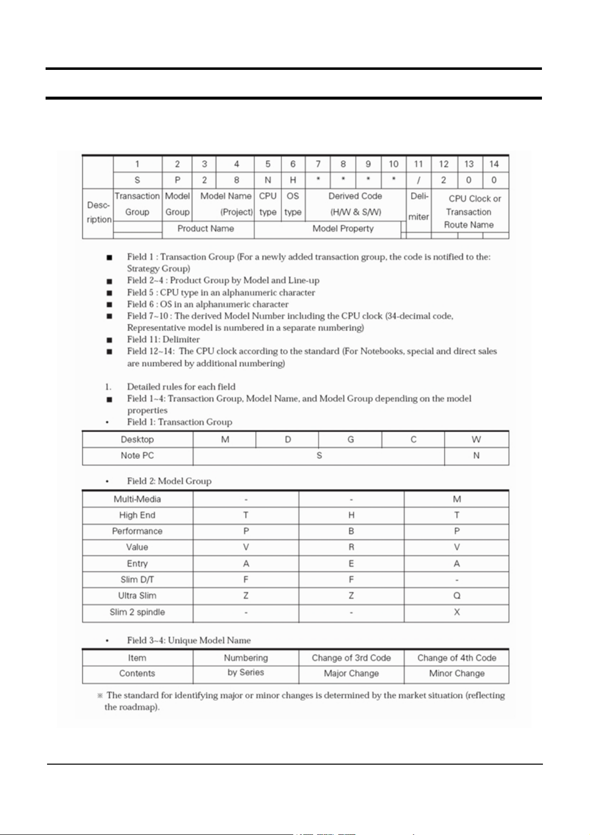
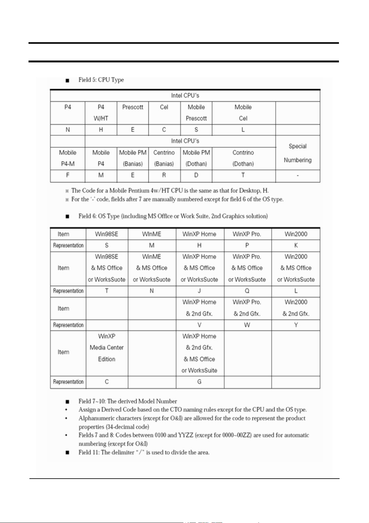
2) Model Numbering Rule
1.
CTO ( Computer Model Numbering System)
11-2
- This Document can not be used without Samsung's authorization -
11. References
11-3
- This Document can not be used without Samsung's authorization -
11. References
2.
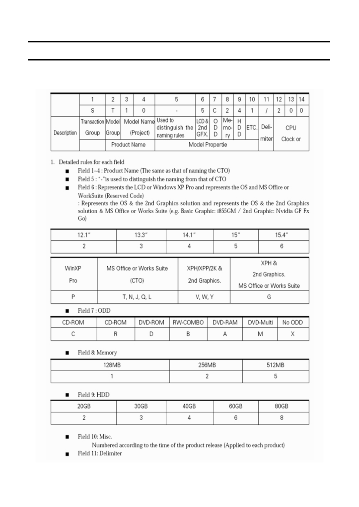
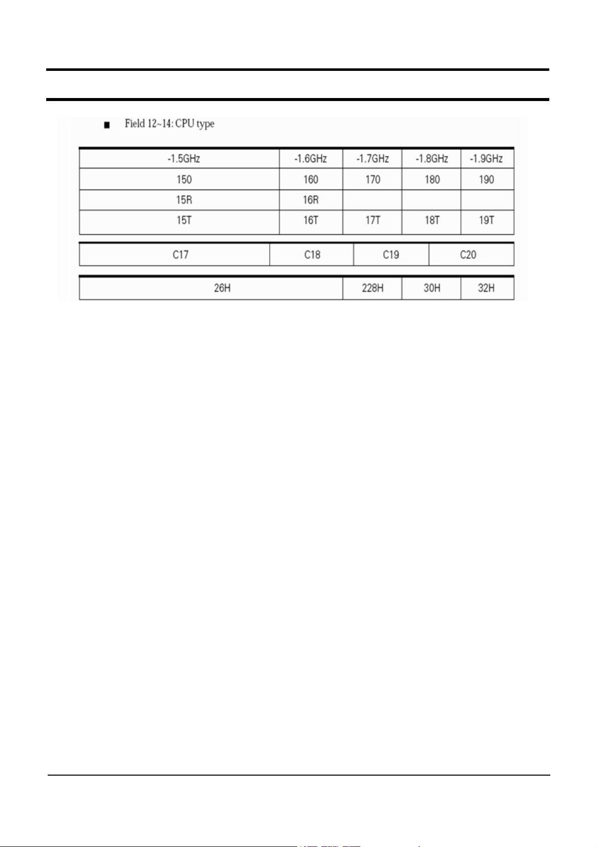
Non - CTO ( Computer Model Numbering System)
11-4
- This Document can not be used without Samsung's authorization -
11. References
11-5
- This Document can not be used without Samsung's authorization -
11. References
3) CPU Code table
Code name Samsung CODE FSB L1 cache L2 cache clock speed
T1300
T2300
T2400
T2500
T2600
T2700
T1400
0902-001943 667MHz 32KB 2M 1.66GHz
0902-001916 667MHz 32KB 2M 1.66GHz
0902-001939 667MHz 32KB 2M 1.83GHz
0902-001938 667MHz 32KB 2M 2.00GHz
0902-001937 667MHz 32KB 2M 2.16GHz
0902-001935 667MHz 32KB 2M 2.33Ghz
0902-001945 667MHz 32KB 2M 1.83GHz
11-6

- This Document can not be used without Samsung's authorization -
11. References
4) Glossary
Bad Sector
An area on a hard disk or floppy disk that cannot be used to store data, because of a
manufacturing defect or accidental damage. A floppy or hard disk saves data in units and the
smallest unit of storage on a disk is a sector. A bad sector means a sector that is damaged and
cannot be used to write or read data.
BIOS
An acronym for Basic Input/Output System. A set of instructions stored on a read-only memory
(ROM) chip which handles all input-output functions. The BIOS communicates between the operating
system and the computer's hardware. This is a part of the computer firmware (computer dedicated
software).
The BIOS allows the computer's hardware and the operating system to communicate with application
programs and peripheral devices as well as providing the fundamental services required for the
computer's operation. To view or change the BIOS settings, press the "Del" key when the system is
booting up.
Boot Sector
The very first track (track 0) on a hard drive of an IBM compatible PC. If the power is turned on,
the booting software reads the first block of the boot sector which contains a very short program (in
the order of a few hundred bytes) which will load and start running the operating system properly.
Bus Mastering
Bus mastering is a feature that enables a CPU extension board or software controller connected to
the bus to communicate directly with other devices on the bus without going through the CPU.
Although the CPU generally controls data communication over the bus (which lowers the data rate),
some high-speed devices may communicate with each other without going through the CPU. To
resolve this problem, a microprocessor installed on an extension board or a piece of software must
take control of the data transfer over the bus. By taking over some of the work of the system
microprocessor, the bus master creates a multiprocessing environment and increases the overall
system performance. This technology is called bus mastering.
Cache
A c ache is temporary high speed memory designed to speed up access to resources. It is similar to
RAM but is much faster than RAM or a hard disk drive. A cache is used to reduce the wait time
caused by the difference in the data rate between two different types of storages such as the hard
disk and the RAM.
11-7

- This Document can not be used without Samsung's authorization -
11. References
Cache Memory
High-speed memory with a copy of the most recently used memory data. When the CPU's request
for instructions or data can be satisfied from the cache, the CPU can run at full rated speed. Using
a part of the hard disk space as cache memory due to small main memory capacity is called disk
cache.
Co-Processor
A specialized processor that performs calculations very quickly under the control of the CPU. There
are two types of co-processors, a numerical co-processor and a memory manager co-processor.
Numerical co-processor does arithmetic calculations or handles graphic processing. In a PC, co-
processor is used to do floating point calculations quickly.
COM Port
Abbreviation of ‘Communications Port’. A COM port refers to the serial communication port provided
by an IBM compatible PC. There are four COM ports supported: COM1, COM2, COM3, and COM4.
These are used to connect a mouse or modem. Since COM 1 and COM 3 perform the same
function and COM 2 and COM 4 perform the same function, avoid setting a mouse or modem to the
same port.
Bay
AspacewithinaPCcasesothatperipheraldevicescanbeinstalled.Ingeneral,aharddiskdrive,
a floppy disk drive and a CD-ROM drive are installed in the bays. 5.25 and 3.5 inch bays are
provided.
CMOS
Abbreviation for ‘Complementary Metal Oxide Semiconductor’. It consumes little power and operates
on battery power. The CMOS saves basic PC information such as the date, time and system
information. A main board has a ROM and a CMOS. The ROM contains a PC checking program and
theCMOScontainsbasicPCinformationsuchastheharddisktype.SincethedataintheCMOSis
maintained by battery power, the data is lost if the battery is completely discharged.
Bus
A collection of wires through which data is transmitted from one part of the computer to another. You
canthinkofabusasahighwayonwhichdatatravelsbetweenpartssuchastheCPU,storage
devices and peripheral devices within a computer. All PC components use data bus to exchange data
or access memory.
There are two types of data bus: address and data bus. Although actual data is transferred through
the data bus, the destination of the data is sent via the address bus. The size of the bus refers to
the width of the bus which determines the amount of data that can be transferred at the same time.
A ‘Bit Bus’ can transfer a bit at a time.
11-8

- This Document can not be used without Samsung's authorization -
11. References
Device Driver
A program stored on the hard drive that tells the operating system how to communicate with an
input/output device such as a printer. You may think of it as dedicated software that controls a
device such as a printer. To use a new peripheral device, the corresponding device driver must be
installed.
DIMM
Abbreviation for ‘Dual In-line Memory Module’. The memory capacity is doubled by installing DRAM
chips on both sides of the memory module. This is similar to a combined 2 SIMM that uses only a
single side. This technology enables a larger capacity without increasing the number of memory
banks by utilizing both sides of the memory module.
Dot Pitch
An indication of the image quality of a monitor, this is the measurement of the distance in millimeters
between two phosphor dots, which is the minimum unit of a s creen on a monitor. It determines the
minimum size of a dot on a monitor. The smaller the dot pitch the better the quality, since it allows
for m ore dots to be displayed and therefore a greater resolution. The dot pitch defines the resolution
of a monitor.
DRAM & SRAM
The highly integrated memory includes two memory devices: DRAM and SRAM. Although DRAM
requires power to maintain data, the circuit density and capacity of DRAM is much higher than
SRAM. The unit capacity, generally, is in MB.
DVD
Abbreviation for ‘Digital Video Disk’. A DVD a large capacity media that can save up to 4.7GB of
data. Due to its high capacity, it is useful for storing multimedia data. The maximum capacity is
17GB and the data rate is between 600Kbps∼1.3Mbps. Since a DVD-ROM drive is also compatible
with existing CD-R media, it will replace the CD-ROM drive in the future.
DVD-RAM
Abbreviation for ‘Digital Versatile Disc-RAM’. A DVD media type that allows multiple data to be written
toadiskandcansaveupto2.6GB,whichisequalto70minutesofaDVDtitleor18001.44MB
floppy disks.
DVD-R Media
A DVD media type that only allows data to be read. Although the basic capacity is 4.7GB, single-
side single-layer, single-side dual-layer, double-side single-layer and double-side dual-layer recording
types are supported. If a DVD disc is recorded via a double-side dual-layer recording, the capacity
increases by 4 times that of the single-side single-layer recording.
11-9

- This Document can not be used without Samsung's authorization -
11. References
EPROM
Abbreviation for ‘Erasable Programmable Read Only Memory’. An EPROM differs from a PROM in
that a PROM can be written to only once and cannot be erased. IF an EPROM is exposed to
ultraviolet light, the data is erased.
An EPROM is covered by transparent glass and 30 minutes of exposure to ultraviolet light erases all
data. To prevent data loss by mistake, place an anti-ultraviolet sticker on the glass of the chip.
Flash Memory
Since flash memory can be written or deleted electrically, you can delete data by blocks and
reprogram the memory. Flash memory can continue to store information in the absence of a power
source, can allow tens of thousands of reading and writing operations, and is expected as the next
generation external storage device that can replace the floppy disk and magnetic disks. It has the
simple structure of a ‘1 bit per element’ and provides more circuit density in a unit area than RAM.
Firmware
This is software that has been written to the ROM or PROM. Firmware is a combination of software
and hardware. It is generally used to improve performance by updating the data saved on the BIOS
or ROM o n the main board.
DAC
Abbreviation for ‘Digital Analog Converter’. DAC converts a digital signal into analog.
WAN (Wide Area Network)
This stands for wide area network. A computer network that spans a wider area than does a local
area network (LAN).
Bluetooth
A global initiative set up in May 1998 by Ericsson (Sweden), IBM and Intel (U.S.) and Nokia
(Finland) to define a standard for cable-free connectivity between mobile phones, mobile PCs, PDAs
and other peripherals for easier use of devices at home and the office. Bluetooth uses short-range
radio links in the 2.4 GHz Instrumentation Scientific and Medical (ISM) band based on IEEE 802.11
specifications.
AGP (Accelerated Graphics Port)
A graphic interface specification developed by Intel. AGP is designed especially for the throughput
demands of 3-D graphics. Rather than using the PCI bus for graphics data, AGP introduces a
dedicated point-to-point channel so that the graphics controller can directly access the main memory.
While the PCI bus operates at 33MHz, AGP operates at 60∼133MHz and provides a much higher
throughput for 3-D graphics.
11-10

- This Document can not be used without Samsung's authorization -
11. References
ALU (Arithmetic-Logic Unit)
Abbreviation for ‘Arithmetic Logic Unit’. A part of the CPU. ALU carries out additions, subtractions,
multiplications and divisions, as well as logical operations within instructions.
AP (Access Point)
An access point is a connection that ties wireless communication devices into a network. The access
point operates independently and is usually connected to an Ethernet hub or server.
FAT (File Allocation Table)
FAT is a file allocation table used by the operating system to keep track of which clusters are
allocated to specific files and which are available for use.
LVDS (Low Voltage Differential Signalling)
LVDS is a digital signal transmission standard developed for the connection of laptop computers to
their local LCD displays and can be run at very high speeds over cheap, twisted-pair copper cables.
The prefix, 'LV', means that it uses 3.3 or 1.5V for signalling instead of the standard voltage, 5V.
POP3 (Post Office Protocol Version 3)
POP3 is the third version of the post office protocol used to deliver emails over the Internet. POP3
is a commonly implemented method of delivering email from the mail server to the client machine
over the Internet.
SMP (Symmetric Multi-Processing)
SMP is a multiprocessor computer architecture where two or more identical processors are connected
to a single shared main memory. SMP systems allow any processor to work on any task no matter
where the data for that task is located in memory. SMP systems can easily move tasks between
processors to efficiently balance the work load. Most common multiprocessor systems today use SMP
architecture.
Skin
This refers to the appearance of a program's user interface or character. Skin can be a graphics or
audio file. A graphics skin can take the appearance of hardware. In other words, a skin allows users
to change the appearance of a program as a user changes the appearance of Winamp or the
Windows background. In general, you can download skins for free from a Web site.
Cookie
A small information text file that certain Web sites copy to a user's hard drive while the user is
browsing a website. A Cookie can contain information such as the user ID, user preferences, archive
shopping cart information, etc. The use of cookies enables a Web site to become more interactive
with its users, especially for future visits. The downside is that the cookie information may expose
information about the visited web sites of the user.
11-11

- This Document can not be used without Samsung's authorization -
11. References
Firmware
Low-level software that controls the hardware. Firmware is a combination of software and hardware.
The name, 'Firmware', is used because it is partly hardware and it is partly software that controls the
underlying hardware of the system.
GPS (Global Positioning System)
GPS is a worldwide positioning system that was developed by the US. Department of Defense in the
1970s. In addition to military purposes, it is permitted to use GPS for general purposes. The error
limit is 50m for military purposes and 200m for general purposes. The DGPS system has been
developed to reduce errors even for general purposes.
Memory Module
An extension board with RAM chips on it.
Bandwidth
The number of bits that can be continuously transmitted or received per second. The higher the
bandwidth the more efficient as data can be transferred in a shorter time.
Address Bus
The data bus used to specify the address of an input or output device or memory by the CPU.
Control Bus
The data bus used to transmit control signals by the CPU so as to notify the storage device, input
or output, of the current status or changes.
rpm (revolutions per minute)
Thisreferstothespeedofreadingdatasavedontheplatterofaharddiskdrive.Itisalsocalled
revolutions per minute or disk revolutions per minute.
Platter
Thisrefertoplatesthatareincludedonaharddiskdriveandusedtorecorddata.Generally,a
harddiskdriveconsistsof2to8platters.
Device
It refers to an electric or mechanical instrument. In PCs, it refers to the active devices used in
electric circuits such as transistor, ICE, etc.
Resistance
An electric characteristic that hinders current flow. All materials except for superconductors have
electric resistance. The symbol is ‘R’. The unit is ‘Ω’.
11-12

- This Document can not be used without Samsung's authorization -
11. References
Audio Frequency
An audio frequency normally audible to humans. Although the audio frequencies may differ depending
on individuals and the volume and type of the sound, audio frequencies range roughly from 20 Hz to
20 kHz.
RTC (Real-Time Clock Generator)
An electronic circuit included on the main board and which maintains the time of day. It operates
even if the computer is turned off, as it operates on separate power. Since keeping the time of the
day is convenient, most computers nowadays adopt this circuit.
IMT-2000 (International Mobile Telecommunication-2000)
This is used in our country and it refers to FPLMTS (Future Public Land Mobile Telecommunication
Systems). The International Telecommunications Union Radio Communication Sector (ITU-R) has
standardized FPLMTS so that anyone can use various communication services (voice and data)
anywhere with a single terminal. Because the pronunciation of ‘FPLMTS’ is difficult, it was renamed
IMT-2000 in 1996.
ACPI (Advanced Configuration and Power Interface)
This is an open industry power management specification co-developed by Intel and Microsoft to
replace the APM (Advanced Power Management) specification. ACPI establishes industry-standard
interfaces for OS-directed configurations and power management on laptops, desktops and servers.
ACPI has been adopted by Windows 98 and Windows 2000. Since ACPI efficiently manages the
power consumption of the system and peripherals, it is especially useful for notebook computers.
Wafer
A round slice of silicon crystal used to create an IC. Micro-circuits such as transistors, resistors and
capacitors are constructed by diffusion (or other doping techniques, such as ion implantation) and the
deposition of various materials. The diameter of a wafer is approximately 5cm and the thinness is
0.25mm. In general, a few tens or hundreds of chips whose height and width are 5mm are
constructed on a wafer. An IC is created by slicing the chips on the wafer.
LED (Light Emitting Diode)
A diode that emits light when the current flows. It is used as an indicator in a PC or as a light
source in optical communications. It is generally made of potassium, arsenic and phosphorus.
Booting
This term derives from the phrase, ‘Wear boots and stand up’. This refers to the processes and
functions that a computer goes through when first starting up, ending with the proper loading of the
Operating System and preparing it for receiving commands.
11-13

- This Document can not be used without Samsung's authorization -
11. References
Dual Core
This refers to a CPU that has dual processing cores within and has been developed by technology
that incorporates two or more Intel Pentium-based processing cores within a single processor.
TPM ( Trusted Platform Module)
The Trusted Platform Module is a component on the desktop board that is specifically designed to
enhance platform security above-and-beyond the capabilities of today's software by providing a
protected space for encrypted keys, passwords and digital certificates so as to provide security
against attacks by external software and physical theft of the hardware.
11-14
- This Document can not be used without Samsung's authorization -
11. References
5) Hardware Upgrade
All reassembly is done in the reverse order of disassembly.
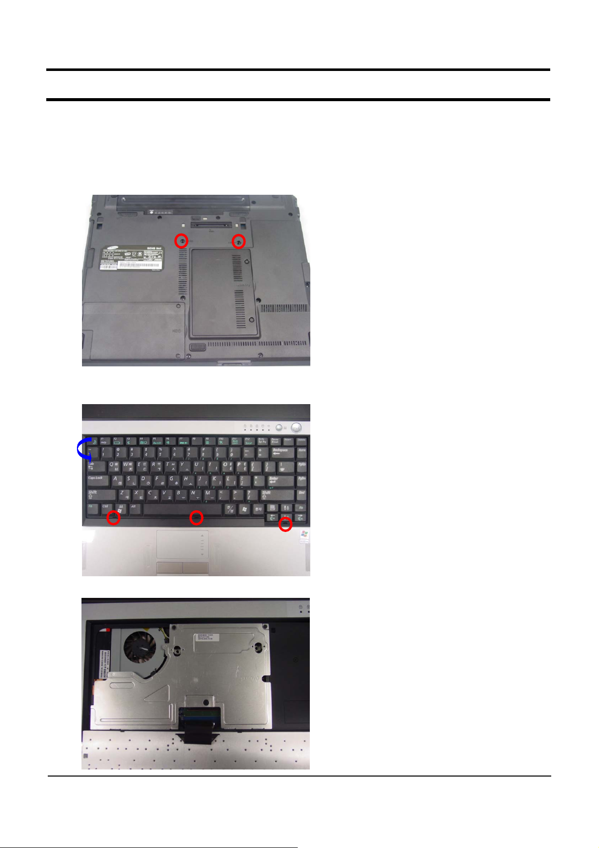
(1) Upgrading the ODD
1. Remove the screws at the bottom of the system.
2. Press the keyboard hooks downwards and lift the keyboard up at the same time.
3. Remove the screws fixing the ODD.
11-15
- This Document can not be used without Samsung's authorization -
11. References
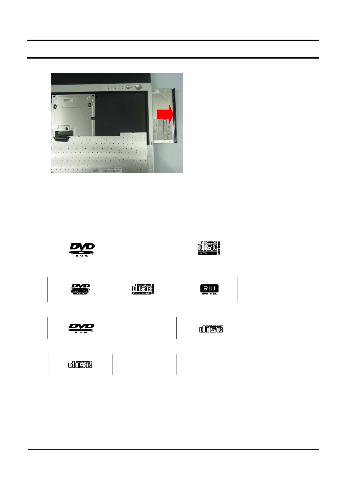
4. Remove the ODD.
5. ODD Types
ODDs that can be used for the R65/P50 include DVD-Combo, CD-ROM, DVD-ROM and
Super Multi Drive (Dual Layer).
- DVD-Combo Drive
- Super Multi Drive (Dual Layer)
-DVD-ROMDrive
- CD-ROM Drive
11-16
- This Document can not be used without Samsung's authorization -
11. References
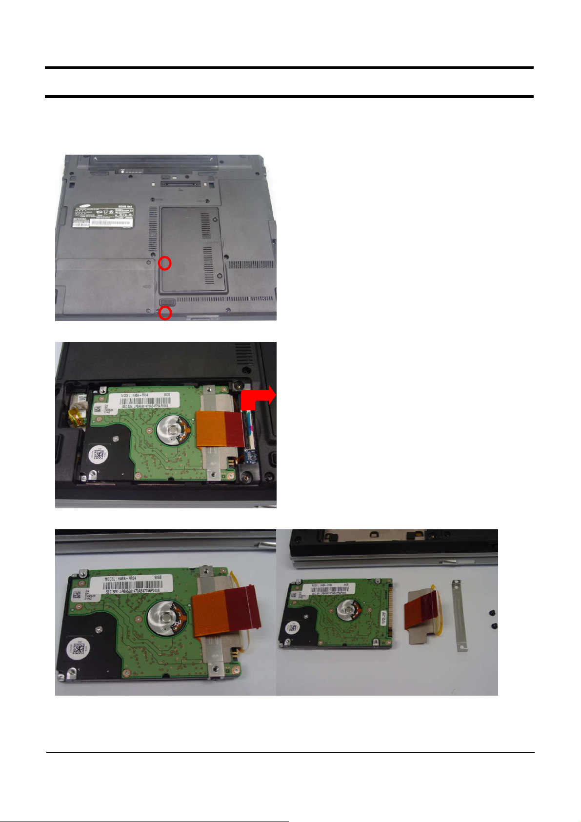
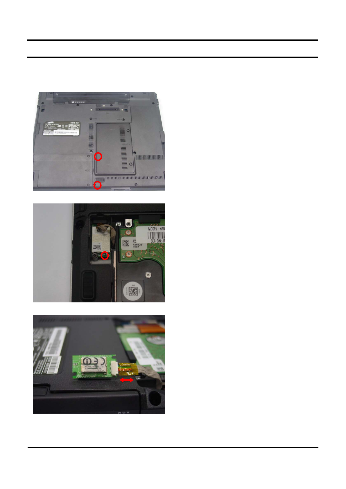
(2) Upgrading the HDD.
1. Remove the HDD compartment cover.
2. Separate the HDD-FPC from the HDD connector on the main board.
3. Separate the HDD from the BRKT-HDD and replace the HDD. (The HDD type is PATA)
11-17
- This Document can not be used without Samsung's authorization -
11. References
(3) Replacing the Bluetooth Module
1. Remove the HDD compartment cover.
2. Remove the screw fixing the Bluetooth module.
3. Replace the Bluetooth module (When replacing the module, note the shape of the cable)
11-18
- This Document can not be used without Samsung's authorization -
11. References
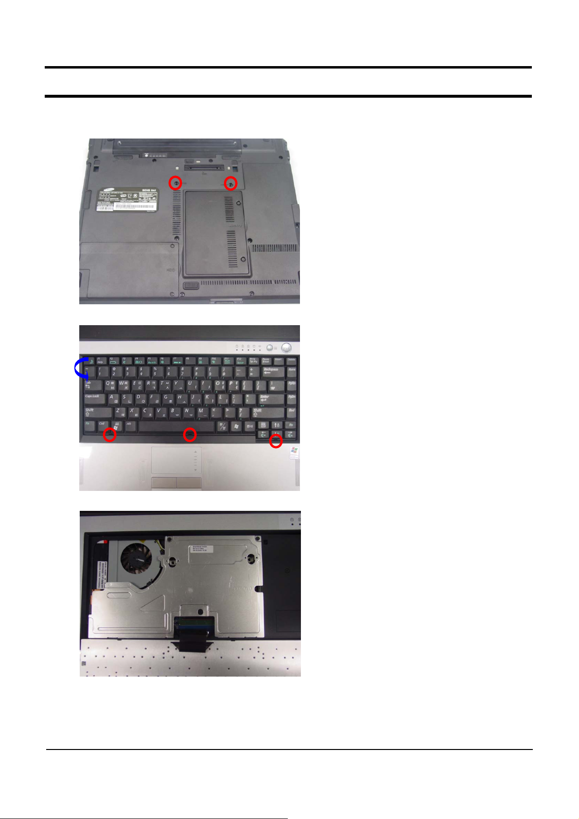
(4) Replacing the WLAN
1. Remove the screws at the bottom of the system.
2. Press the keyboard hooks downwards and lift the keyboard up.
3. Remove the screws fixing the BRK-KBD.
11-19
- This Document can not be used without Samsung's authorization -
11. References
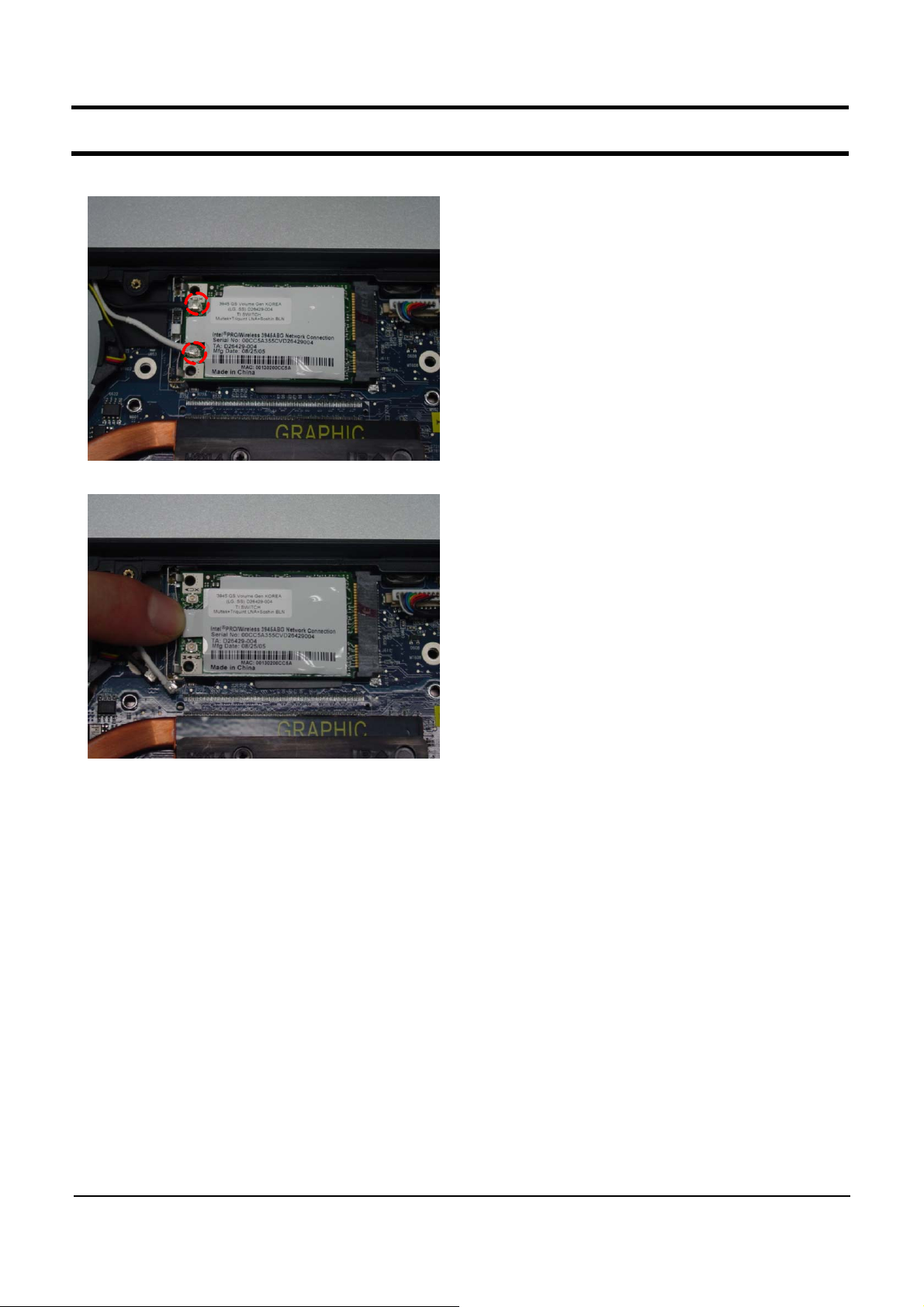
4. Remove the WLAN Cable-Antenna.
5. Remove the WLAN (Lift the WLAN up sliding the WLAN hook left)
11-20
- This Document can not be used without Samsung's authorization -
11. References
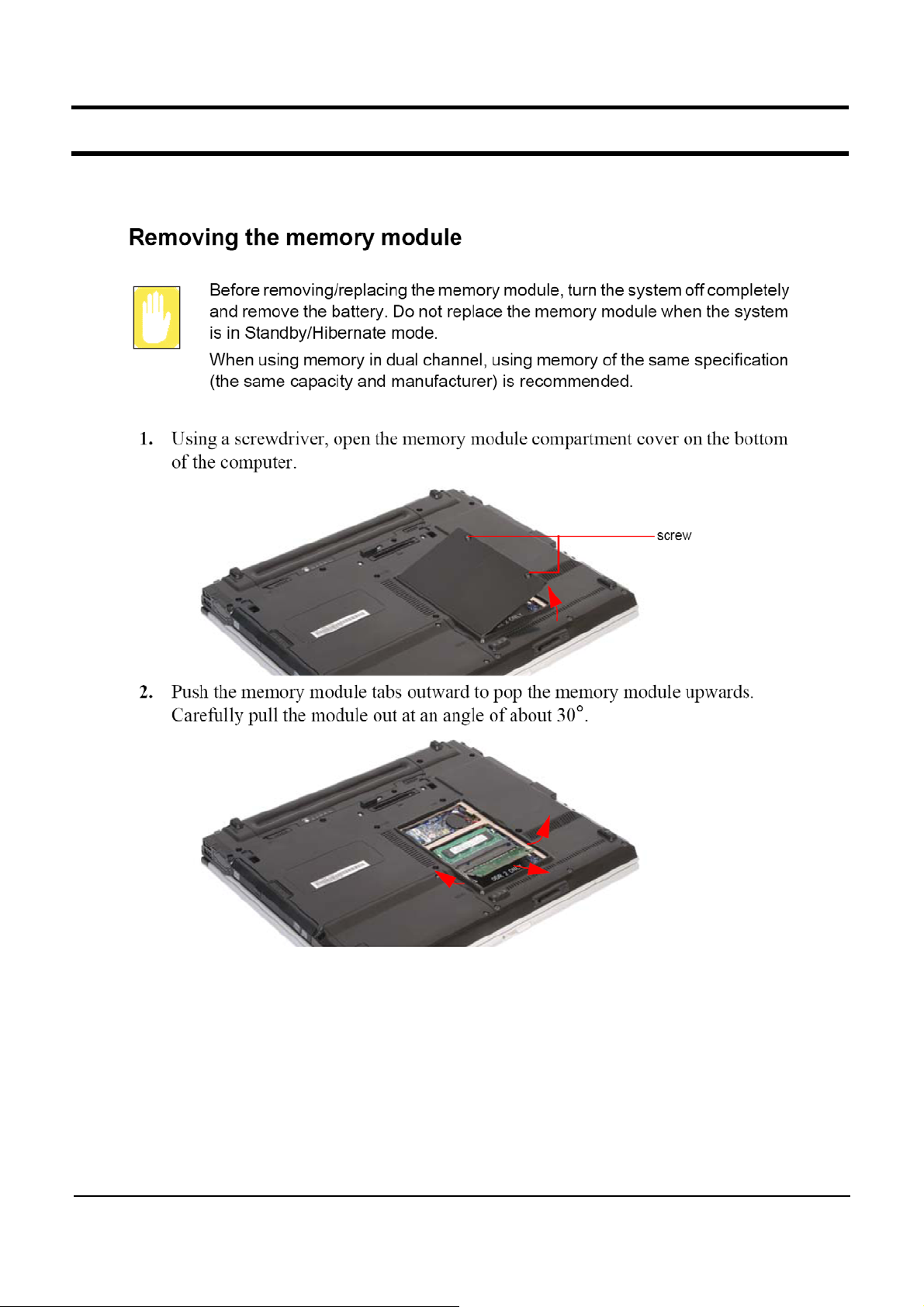
(5) Upgrading Memory
11-21
- This Document can not be used without Samsung's authorization -
11. References
11-22
- This Document can not be used without Samsung's authorization -
3. Function
1)
Construction of System
3- 1
- This Document can not be used without Samsung's authorization -
3. Function
3- 2

- This Document can not be used without Samsung's authorization -
3. Function
3- 3

- This Document can not be used without Samsung's authorization -
3. Function
3- 4

- This Document can not be used without Samsung's authorization -
3. Function
2) Keyboard
3- 5

- This Document can not be used without Samsung's authorization -
3. Function
3- 6

- This Document can not be used without Samsung's authorization -
3. Function
3) Multi Card Slot
3- 7

- This Document can not be used without Samsung's authorization -
3. Function
3- 8

- This Document can not be used without Samsung's authorization -
3. Function
3- 9

- This Document can not be used without Samsung's authorization -
3. Function
4) PC Card Slot
3- 10

- This Document can not be used without Samsung's authorization -
3. Function
5) SPDIF Port
3- 11

- This Document can not be used without Samsung's authorization -
3. Function
3- 12

- This Document can not be used without Samsung's authorization -
3. Function
3- 13

- This Document can not be used without Samsung's authorization -
3. Function
6) ASF and Core Multi Processing.
-. ASF (Alert Standard Format)
ASF configuration : "CMOS setup -> Advanced -> ASF Configuration."
-. Core Multi Processing
Core Multi Processing configuration : CMOS Setup -> Advanced -> Core Multi Processing.
▶ ASF Configuration
▶ ASF Configuration
Core Mullti-Processing [Enabled]
Core Mullti-Processing [Enabled]
Intel® SpeedStep™ [Enabled]
Intel® SpeedStep™ [Enabled]
Touch Pad & PS/2 Mouse [Enabled]
Touch Pad & PS/2 Mouse [Enabled]
Legacy USB Support [Enabled]
Legacy USB Support [Enabled]
Boot from 1394/Firewire [Disabled]
Boot from 1394/Firewire [Disabled]
Large Disk Access Mode [DOS]
Large Disk Access Mode [DOS]
▶ I/O Device Configuration
▶ I/O Device Configuration
EDB (Execute Disable Bit) [Disabled]
EDB (Execute Disable Bit) [Disabled]
Internal LAN [Enabled]
Internal LAN [Enabled]
CPU Power Saving Mode [Enabled]
CPU Power Saving Mode [Enabled]
Delete Recovery Area [Disabled]
Delete Recovery Area [Disabled]
Purchased Date 2005/10
Purchased Date 2005/10
ExitBootSecurityAdvancedMain
ExitBootSecurityAdvancedMain
Item Specific Help
Item Specific Help
Select ‘Yes’ if you
Select ‘Yes’ if you
are using a Plug &
are using a Plug &
Play capable
Play capable
operating system.
operating system.
Select ‘No’ if you
Select ‘No’ if you
need the BIOS to
need the BIOS to
configure non-boot
configure non-boot
devices.
devices.
F1 Help
F1 Help
ESC Exit
ESC Exit
ÏÐ Select Item
ÏÐ Select Item
ÍÎ Select Menu
ÍÎ Select Menu
F5/F6 Change Values
F5/F6 Change Values
Enter Select ► Sub-Menu
Enter Select ► Sub-Menu
3- 14
F9 Setup Defaults
F9 Setup Defaults
F10 Save and Exit
F10 Save and Exit

- This Document can not be used without Samsung's authorization -
3. Function
7) Description of Main board
(1) TOP
No. Item No. Item
1 CPU 14 LAN Jack Combo
2 MCH-Calistoga 15 Battery Connector
3 ICH7-M 16 Keyboard Connector
4 GFX Board Conn. (Internal board no-stuff) 17 On-top Board Connector
5 MiniCard for Wireless LAN 18 SIO Cable
6 5-in-1 Slot (Biz model no-stuff) 19 USB Cable
7 PCMCIA & Express Frame 20 Bluetooth Cable
8 LCD Cable Connector 21 1394/IRDA Cable
9 ODD Connector 22 Touchpad Connector
10 USB/SIO Board 23 SIO Connector
11 1394/IRDA Board 24 WLAN Slide Switch
12 System Fan 25 SVHS Connector
13 DC Jack 26 VGA Connector
3- 15

- This Document can not be used without Samsung's authorization -
3. Function
(2) BOTTOM
No. Item
1 Docking Connector
2Micom
3 Azalia Modem
4 TPM Connector (Home model no-stuff)
5RTCBattery
6 Modem Cable
7 Clock Generator
8 DDR2 SODIMM Memory Connector
9 LAN Controller
10 BIOS
11 HDD Connector
12 LAN Transformmer
3- 16

- This Document can not be used without Samsung's authorization -
3. Function
(3) GFX BOARD BOTTOM
No. Item
1GFXChip
2GFXConnector
3 GDDR3 Memory
3- 17

- This Document can not be used without Samsung's authorization -
2. Introduction and Specification
1) Introduction
(1) High Performance Note PC
High Performance Note PC with Intel Pentium M CPU and DDR II Memory.
-
PCI-Express Graphics (Option)
-
Wireless LAN (Option), Bluetooth (Option), IrDA.
-
(2)ConvenientAV
Offer of Integrated Multi-Media Program, AVStation.
-
Users can enjoy Music, Picture and Movie with AVStation conveniently.
Use of
-
Use of
(Home model only)
AVStation premium when the PC is power-on,
AVStation now
when the PC is power-off.
(3) High Stability and Offer of convient management function.
Offer of strong security function through the FingerPrint (Biz model only)TPM(Bizmodelonly)
-
(4) Prudent Design for easy use.
AVS button (Home model only), Wireless LAN switch,
-
Use of Various memory card through Multi card slot (Home model only)
-
Good feeling and design through the Flat type touchpad
-
.
2- 1

- This Document can not be used without Samsung's authorization -
2. Introduction and Specification
(5) Home model (R65)
Special feature of Home model(R65)
High gloss
-.
Convient
-.
Special feature of Biz model(P50)
-. TPM (option), Fingerprint (option)
-. ASF
Form Factor (LCD) 15" Super Bright Glare LCD 15" Super Bright LCD
Platform (Chipset) Yonah+Calistoga-PM/GM
System management
Feature
Memory Dual channel 667,533,400Mhz
Wireless
15" LCD (Glare)
Multi Media
and
Business model (P50)
function
.(AVSnow&MultiMemoryCardSlot[5in1])
Solution (Option)
R65 P50
802.11bg(option), 802.11abg(option), IrDA, BT(option)
Graphics Ext(Discrete Memory, Daughter Card)/Int Graphics
HDD PATA, SATA (Ready)
ODD Fixed ODD, Combo/Super Multi Fixed ODD, CD/Combo/Super Multi
Network 10/100M LAN 10/100M LAN / Gigabit ASF
Security(option) FingerPrint, TPM, Smartcard
AV Stero Speaker, SRS MIC Noise Reduction.
4USB, 1394, MS, MSPro, SD, xD,
Ports
Docking X-Dock
Mechanical
Design
MMC,Micin,HP-out(SPDIF),PC
Express card, S-VHS, SIO(option),LAN
30mm~35mm, Under 2.7Kg, All PC+ABS
Home Basic Design
(Bottom Un-painted)
card
4USB, 1394, Mic in, HP-out (SPDIF),
,
card
PC
,Expresscard,S-VHS,SIO,LAN
Business Basic Design
(Bottom Un-painted)
2- 2

- This Document can not be used without Samsung's authorization -
2. Introduction and Specification
2) Specification
Processor and Motherboard P50 / R65
Intel Yonah Processor Dual-core T2300(1.66GHz) ~ T2700(2.33GHz)
Intel Yonah Processor Single-core T1300(1.66GHz) ~
T1400(1.83GHz)
CPU
- Intel® Centrino® Mobile Technology with Intel® Core™
Processor
: Intel Core processor (Dual core Yonah)+ i945 chipset + 3945ABG
WLAN
- Intel® Centrino® Mobile Technology
: Intel Pentium M (Single core Yonah)+ i945 chipset + 3945ABG
WLAN
Speed
Cache 2MB L2 cache
Chipset Intel 945PM /945GM+ ICH7M
BIOS 8 Mbit, Flash upgradable
Thermal Design Performance MAX. 34W
Memory
Memory / Max. Memory 256MB / Max.4GB
Memory type
Memory Modules 256MB, 512MB, 1GB SODIMM
Sockets 2-slot SODIMM's
Display and Graphics
LCD 15" XGA /SXGA+ (R65:Glare, P50: Non-Glare)
LCD Vendor
15.0" XGA
LCD Viewable Area 304 x 228mm (HxV)
LCD Resolution 1024 x 768 x 262,144 color ( 18 bit )
Dot Pitch 0.297 x 0.297mm (HxV)
Viewing angle Hor. +45/-45,Ver. +15/-35
Contrast Ratio typ.200 (CR)
Brightness min.170, typ.200(cd/m2)
Response time Risingtyp.10ms / max.15ms,Fallingtyp.30ms / max.35ms
15.0" SXGA+
LCD Viewable Area 304 x 228mm (HxV)
Intel Core ProcessorT1300(1.66GHz) ~ T1700(2.33GHz)
Intel Pentium M Processor756(1.66GHz) ~ 766
PC2-3200(400MHz) / PC2-4200(533MHz) / PC2-5300(667MHz)DDR2
SODIMM
(1.83GHz)
Samsung AMLCD (LTN150XG-L05-V)
Samsung AMLCD (LTN150PG-L03-V)
2- 3

- This Document can not be used without Samsung's authorization -
2. Introduction and Specification
Viewing angle Hor. +60/-60,Ver. +45/-45
Contrast Ratio min.300 (CR)
Brightness min.180, typ.200(cd/m2)
Factory option
Graphics Controller
Intel GMA 950 Intel 945GM Express Chipset
Video Memory 64MB / 128MB with DVMT
Max.Resolution for LFP
LVDS
Max.Resolution for External
Monitor
NVIDIA External GFx NVIDIA GeForce GO 7300/7400/7600
Video Memory
Max.Resolution for LFP
LVDS
Max.Resolution for External
Monitor
Intel GMA 950_DVMT 128MB
NVIDIA GeForce GO 7300_256MB (Physical 64MB + TurboCache
192MB) / (Physical 128MB + TurboCache 128MB)
NVIDIA GeForce GO 7400_256MB (Physical 64MB + TurboCache
192MB) / (Physical 128MB + TurboCache 128MB)
NVIDIA GeForce GO 7600_256MB (Physical 256MB)
1400 * 1050 x 32Bits color (SXGA+)
2048 x 1536 @75HZ (CRT)
NVIDIA GeForce GO 7300_256MB (Physical 64MB + TurboCache
192MB) / (Physical 128MB + TurboCache 128MB)
NVIDIA GeForce GO 7400_256MB (Physical 64MB + TurboCache
192MB) / (Physical 128MB + TurboCache 128MB)
NVIDIA GeForce GO 7600_256MB (Physical 256MB)
1400 * 1050 x 32Bits color (SXGA+)
2048 x 1536 @85HZ (CRT)
Audio
Sound High Definition Audio
Controller HD Audio Codec,AD1986A
Conversion Built-in high performance 20-bit ADC & 24-bit DAC
Internal Interfaces Embedded 2 stereo speakers, Internal microphone (Biz option)
Speaker Power Rating 2 Speakers x 2 Watt with enclosure each
External Interfaces Microphone, Headphone, Optical S/PDIF out port
Controls Keyboard volume control, SRS enable / disable
Microphone (P50 only) Mono Microphone
Microphone
Sensitivity
Output Impedance
Storage
Mono
-44dB
2.2KΩ
2- 4

- This Document can not be used without Samsung's authorization -
2. Introduction and Specification
Hard Disk Drive 9.5mmH 2.5" HDD, Removable
Supports SMART UltraDMA-33/66/100 support
Average Access Time 13m sec.
Speed
Capacity
Optical Disk Drive CD(Biz option) / Combo / Super Multi (12.7mm)
Type Fixed type (Factory Option)
S/W supplied Power DVD Player , Burning function in Windows XP
Security RPC-II Regional Encoding
4200rpm,5400rpm,7200rpm
PATA, SATA(ready)
40GB / 60GB / 80GB / 100GB / 120GB : HGST, Hitachi, Samsung
- 40 ~ 120 GB PATA 4200rpm
- 40 ~ 100GB PATA 5400rpm
- 60 ~ 80GB PATA 7200rpm
- 40 ~ 100GB SATA 5400rpm
Optical Driver Modules
CD-ROM Drive 1 Factory Option
Module type Fixed 12.7mm Slim
Speed 24x CD :
Average Access Time CD 110ms Typ
Weight 165g or less
Combo Drive 1 Factory Option
Module type Fixed 12.7mm Slim
Speed 8x DVD-ROM, 24x RW, 24x CD-R, 24x CD :
Average Access Time SEC: DVD 130ms Typ, CD 130ms Typ, CD-RW 130ms Typ.
Weight 180g or less
S/W supplied Power DVD Player (5.0), Nero Burning or equivalent S/W
Security RPC-II Regional Encoding
Combo Drive 2 Factory Option
Module type Fixed 12.7mm Slim
Speed 8x DVD-ROM, 24x RW, 24x CD-R, 24x CD :
Average Access Time DVD 110ms Typ., CD 90ms Typ.
Weight 190g or less
S/W supplied Power DVD Player (5.0), Nero Burning or equivalent S/W
Security RPC-II Regional Encoding
Super Multi Dual Layer 1 Factory Option
Module type Fixed 12.7mm Slim
Speed
Average Access Time DVD 130ms Typ., CD 130ms Typ.
TEAC, CD-224EN
TSST, TS-L462C
Teac, DW-224E-C
5x DVD-RAM, 8x DVD
16x CD-RW, 8x DVD, 24x CD : TEAC DV-W28EA
±R 2.4x DVD+R DL, 4x DVD±RW,24x CD-R,
2- 5

- This Document can not be used without Samsung's authorization -
2. Introduction and Specification
Weight 190g or less
S/W supplied Power DVD Player (5.0), Nero Burning or equivalent S/W
Security RPC-II Regional Encoding
Super MultiDual Layer 2 Factory Option
Module type Fixed 12.7mm Slim
Speed
Average Access Time DVD 180ms Typ., CD 150ms Typ.
Weight 190g
S/W supplied Power DVD Player (5.0), Nero Burning or equivalent S/W
Security RPC-II Regional Encoding
5x DVD-RAM, 8x DVD
10x CD-RW, 8x DVD, 24x CD : Matsubshita UJ-840B
±10g
±R 2.4x DVD+R DL, 4x DVD±RW,24x CD-R,
Network Tools
Fax/Modem 56Kbps / V.92 Azalia Modem
Chipset SV92A1
Features RJ11 Output
LAN 10/100 Ethernet UTP (Factory option)
Chipset Broadcom BCM4401
Features RJ45 Output
LAN 1Gb Ethernet with ASF (Factory option)
Chipset Broadcom BCM5751
Features RJ45 Output
802.11g Wireless LAN Intel PRO/Wireless 3945BG:
Type Mini card (Factory Option) ;;
Chipset Golan
Antenna Integrated 2 Antenna
802.11a/g Wireless LAN Intel PRO/Wireless 3945ABG:
Type Mini card (Factory Option) ;;
Chipset Golan
Antenna Integrated 2 Antenna
Bluetooth BCM92045NMD : Factory Option
Type USB daughter card with integrated PIFA antenna
Chipset Broadcom BCM2045
Standard version 2.0
IRDA TFDU6102
Chipset LPC47N207
Feature FIR, 4Mbit/s
Intel 802.11b/g
Only for Thailand / Ukraine
Intel 802.11a/b/g
Not allowed in Thailand / Ukraine
I/O Interface
PC CardBus Slots 1 PCMCIA Type II slot
2- 6

- This Document can not be used without Samsung's authorization -
2. Introduction and Specification
Controller Ricoh R5C841
Support 32bit CardBus cards
Express Card Slots 1 Express card slot
Type USB Type
Support USB Type + Express Type
I/O Ports
iEEE1394 Port 1(4pin)
USB Port 4(USB2.0)
Video Port 1
TV-out connector S-VHS
Audio Jacks HeadPhone-out ,Optical S/PDIF, MIC-in
Modem / LAN RJ11, RJ45
Serial Port 1(P50:All,R65:option)
IrDA (FIR) 1
Docking 120p
Power 1(5pie)
Input Devices
Key board 88KEY(KR/US), 89KEY(UK/FR/GM/SP)
Touchpad Synaptics Touchpad (Plat type with Scroll area)
Easy Button Internet(P50) or MIO(R65) / Wireless On_Off
Travel length 2.6mm/ Key Pitch 19.05mm
Special Feature
FingerPrint (P50 only) Authentic : Factory Option
Bus type USB
Function Replacement of Boot-up & Log-on & All Windows Password
Application S/W Omnipass 3.0
TPM (P50 only) Trusted Platform Module : Factory Option
Controller Infineon
Bus type LPC
Function Manage users and Certificates, file and folder encrytion
S/W Infineon TPM Professional Package
ASF (P50 only) Alert Standard Format : Factory option
Chipset
Speed 1Gigabit
Features RJ45 Output
Application S/W TBD
Power and Power
Management
Battery AA-PB2NC6B (6cells, Smart Li-Ion Battery)
Broadcom 5751
2- 7

- This Document can not be used without Samsung's authorization -
2. Introduction and Specification
Dimension 204x48.05x21.4mm
Weight 330g (max)
Recharge Time 2 hours to 100% with Windows on & off
Battery Life over 6.5hour ( Battery mark 4.01)
Details of Cell 6cells (2Parallel 3Serial)
Voltage 11.1Vdc
Battery Capacity 2600mAh/cell
Battery Rating 11.1V / 5200mAh (57.72Wh)
Battery AA-PL2NC9B (9cells, Smart Li-Ion Battery)
Dimension 204x67.0x21.4mm
Weight 470g (max)
Recharge Time 3 hours to 100% with Windows on & off
Battery Life over 9.0hour ( Battery mark 4.01)
Details of Cell 9cells (3Parallel 3Serial)
Voltage 11.1Vdc
Battery Capacity 2600mAh/cell
Battery Rating 11.1V / 7800mAh (86.58Wh)
AC Adapter AD-9019S
Output Power 90Watts
Dimension 133 X 58 X 30.5mm
Weight (AC Adapter) 420g (typ)
Worldwide Compatibility Auto-sensing 100 - 240VAC
Line Frequency 50 / 60Hz
Adapter Rating - Input 100V - 240V, 1.4A
Adapter Rating - Output 19.0VDC / 4.74A
Power Management
Features
ACPI 1.0b support, Standby(S3), Hibernate(S4)
System Dimensions
Dimensions (W X D X H) 329.8 x 272 x 30.7 mm
Weight (Full system w/ 6cell
Battery)
Materials LCD back / Top : PC/GF
2.7kg
Status : No options, 6cell battery, 15" LCD
Bottom / Front : PC/ABS
2- 8

- This Document can not be used without Samsung's authorization -
2. Introduction and Specification
3) Specification comparison between R50 and R65.
R50 R65
R50 P50 / R65
CPU 533MHz Pentium M 667MHz Pentium M (Yonah)
Chipset 915 945(Calistoga)
Memory DDR2 400 / 533MHz DDR2 400 / 533 / 667MHz
Graphic ATI M22 / M24C Nvidia G72 / G73, Intel 945GM
LCD 15.4” 15”
HDD PATA / SATA PATA / SATA (ready)
ODD 12.7mm 12.7mm
Port 4 USB
Battery M50 6cell / 9cell
X-Dock, 4USB, SIO(option), IrDA,
BT(option)
New
6cell / 9cell
Design Prototype Design Prototype Design
2- 9

- This Document can not be used without Samsung's authorization -
2. Introduction and Specification
4) Wireless LAN Specification
(1) Wireless LAN
Intel(R) PRO/Wireless LAN 3945ABG Network Connection
Standard
(802.11ABG
card
)
Device
2- 10

- This Document can not be used without Samsung's authorization -
2. Introduction and Specification
2- 11

- This Document can not be used without Samsung's authorization -
2. Introduction and Specification
5) Option list
HDD
BA59-01747A 40GB (4.2KR) 40G,HTS421240H9AT 00,S63,H16,C16383,H9.5,W100*L69.85mm
BA59-01639A 40GB (4.2KR)
BA59-01746A 60GB (4.2KR)
BA59-01819A 60GB (4.2KR) 60GB,MHV2060AT-L,S63,H16,C16383,H9.5,W100*L69.85mm
BA59-01702A 80GB (4.2KR) 80G,HTS421280H9AT 00,S63,H16,C16383,H9.5,W100*L69.85mm
BA59-01820A 80GB (4.2KR) 80GB,MHV2080AT-PL,S63,H16,C16383,H9.5,W100*L69.85mm
BA59-01703A 100GB (4.2KR) 100G,HTS421210H9AT00,S63,H16,C16383,H9.5,W100*L69.85mm
BA59-01821A 100GB (4.2KR) 100GB,MHV2100AT-PL,S63,H16,C16383,H9.5,W100*L69.85mm
BA59-01701A 120GB (4.2KR) 120G,HTS421212H9AT00,S63,H16,C16383,H9.5,W100*L69.85mm
BA59-01822A 120GB (4.2KR) 120GB,MHV2120AT-PL,S63,H16,C16383,H9.5,W100*L69.85mm
BA59-01649A 40GB (5.4KR) 40GB,MHV2040AH,S63,H16,C16383,H9.5,W100*L69.85mm
BA59-01469A 40GB (5.4KR) 40G,HTS541040G9AT00,S63,H16,C16383,9.5mm
BA59-01748A 40GB (5.4KR) 40G,MP0402H,S63,H16,C77622,9.5mm
BA59-01650A 60GB (5.4KR) 60GB,MHV2060AH,S63,H16,C16383,H9.5,W100*L69.85mm
BA59-01470A 60GB (5.4KR) 60G,HTS541060G9AT00,S63,H16,C16383,9.5mm
BA59-01744A 60GB (5.4KR) 60G,MP0603H,S63,H16,C77622,9.5mm
BA59-01651A 80GB (5.4KR) 80GB,MHV2080AH,S63,H16,C16383,H9.5,W100*L69.85mm
BA59-01471A 80GB (5.4KR) 80G,HTS541080G9AT00,S63,H16,C16383,9.5mm
BA59-01745A 80GB (5.4KR) 80G,MP0804H,S63,H16,C77622,9.5mm
BA59-01652A 100GB (5.4KR) 100GB,MHV2100AH,S63,H16,C16383,H9.5,W100*L69.85mm
BA59-01725A 100GB (5.4KR) 100G,HTS541010G9AT00,S63,H16,C16383,H9.5,W100*L69.85mm
40GB,MHV2040AT,S63,H16,C16383,H9.5,W100*L69.85mm
60G,HTS421260H9AT00,H16,C16383,H9.5,W100*L69.85mm
HDD FPC
BA41-00568A
BA41-00569A
MODEM
BA59-01577A Foxconn T60M893.05
BA59-01578A ASKEY 1456VQL-T1(INT-LF)
K01188A3
CSS-D02D
PATA HDD FPC(AFC)
2- 12

- This Document can not be used without Samsung's authorization -
2. Introduction and Specification
ODD
BA96-03003A S-MULTI(D/L) DV-W28EA
BA96-03011A Combo DW-224E-C
BA96-03010A Combo TS-L462C
BA96-02999A DVD-ROM DV-28EN
BA96-03059A CD-ROM CD-224E-N
MEMORY
1105-001610 512M(SEC) DDR2 533 512MB SO-DIMM M470T6554CZ3-CD5
1105-001609 256M(SEC) DDR2 533Mhz 256MB M470T3354BG0-CD5
1105-001614 256M(IN) DDR2 533Mhz 256MB YS64T32000HDL-3.7-A
1105-001610 512M(SEC) DDR2 533Mhz 512MB M470T6554BG0-CD5
1105-001615 512M(IN) DDR2 533Mhz 512MB HYS64T64020HDL-3.7-A
1105-001611 1GB(SEC) DDR2 533Mhz 1GB M470T2953BS0-CD5
1105-001682 256M(SEC) DDR2 667Mhz 256MB M470T3354CZ3-CE6 (
1105-001685 256M(IN) DDR2 667Mhz 256MB HYS64T32000HDL-3S-A (
1105-001683 512M(SEC) DDR2 667Mhz 512MB M470T6554CZ3-CE6 (
1105-001686 512M(IN) DDR2 667Mhz 512MB HYS64T64020HDL-3S-A (
1105-001684 1GB(SEC) DDR2 667Mhz 1GB M470T2953CZ3-CE6 (
1105-001687 1GB(IN) DDR2 667Mhz 1GB HYS64T128021HDL-3S-A (
CPU
0902-001943 T1300 Single core 1.66GHz
0902-001916 T2300 Dual core 1.66GHz
0902-001939 T2400 Dual core 1.83GHz
적용예정
적용예정
적용예정
)
적용예정
)
적용예정
)
적용예정
)
)
)
0902-001938 T2500 Dual core 2.00GHz
0902-001937 T2600 Dual core 2.16GHz
2- 13

- This Document can not be used without Samsung's authorization -
2. Introduction and Specification
LCD PENEL
BA59-01567A XGA-G LTN150XG-L05-G
BA59-01749A XGA-G N150X3-L08
BA59-01719A SXGA+G LTN150PG-L03-E
BA59-01811A XGA-NG LTN150XG-L05-V
BA59-01750A XGA-NG N150X3-L09
BA59-01402A SXGA+NG LTN150PG-L03-V
BA59-01751A SXGA+NG N150P5-L02
BATTERY
BA43-00149A
BA43-00150A
BLUETOOTH
BA59-01691A BLUETOOTH BCM92045NMD
WLAN
BATTERY(6CELL) SDI Battery 6Cell
BATTERY(6CELL) Sanyo Battery 6cell
BA59-01723A 802.11a/b/g WM3B3945AGKOR
BA59-01722A 802.11a/b/g WM3B3945AGROW
BA59-01721A 802.11a/b/g WM3B3945AGMOW1
BA59-01724A 802.11a/b/g WM3B3945AGMOW2
BA59-01795A 802.11 b/g WM3B3945BG
2- 14

- This Document can not be used without Samsung's authorization -
2. Introduction and Specification
6) The seperate sale list
Docking
AA-RD1NX25 / XX X-Docking
2- 15

- This document cannot be used without Samsung's authorization -
4. Disassembly and Reassembly
4-1. Disassembly and Reassembly of R65
Part
Figure Description
1. Make sure to separate the AC adapter and
battery before disassembling the system.
2. Slide the knob all the way to the end in the
direction of the arrows (1) and push the battery
in the direction of the arrows (2).
3.Ifyoupushthebatteryupwards,thebattery
is separated.
Main
System
4. Remove the screws from the bottom.
5. Remove the HDD compartment cover.
6. Remove the memory compartment cover.
4-1

- This document cannot be used without the authorization of Samsung -
4. Disassembly and Reassembly
Part
Main
System
Figure Description
7. When removing the HDD compartment cover,
you will find the HDD. Separate the HDD cable
andliftuptheHDDatanangleof70ºas
showninthefigure.
(To separate the HDD cable, lift up the cable
connector.)
*Caution
DonotlifttheHDDupusingexcessiveforce.
Make sure to remove the HDD before turning
over the system.
8.
1) Lift right side first
2) Separate Cap-Top lower side to 2 of 3
3) Separate right Hinge Cap
5
4
2
3
4) Separate Cap-Top lower side fully
1
5) Separate left Hinge Cap
Caution : Be careful to happen scratch on LCD-
Front because of excessive force when you
disassemble Hinge-Cap area.
9. You have to unlock 3 hooks in the order of 1,
2 and 3 to remove the keyboard as shown in
the figure.
10. Push the hooks inwards using tweezers as
thefigureshowsandliftupthekeyboard.
*Caution
AvoidscratchingtheTopwhenpushingthe
hook with the tweezers.
4-2

- This document cannot be used without the authorization of Samsung -
4. Disassembly and Reassembly
Part
Figure Description
11. Lift up the keyboard, then the Connector
Lock and separate the FPC.
12. Remove the 2 screws fixing the BracketSupport_KBD and remove the bracket.
Main
System
13. Disconnect the antenna cable connected to
the wireless LAN and take the cable out in the
direction of the arrow. (1: Aux,2: Main)
14. Hold and pull the black string (3) in the
figure to take the LCD cable out.
15. Remove the screw fixing the ODD bracket
and the PCB.
4-3

- This document cannot be used without the authorization of Samsung -
4. Disassembly and Reassembly
Part
Figure Description
16. Remove the 2 screws fixing the Hinge and
the Top.
17. Lift up the Assy LCD slightly and separate it
by pulling it in the direction of the arrow.
Main
System
18. Separate the ODD as the figure shows.
19. (1) Remove the screw fixing the Top and
Bottom.
(2) Remove the screw fixing the Top and the
Bluetooth module.
4-4

- This document cannot be used without the authorization of Samsung -
4. Disassembly and Reassembly
Part
Figure Description
20. (1) Separate the Ontop cable from the Main
board.
(2) Separate the Speaker cable from the Main
board.
(3) Separate the Touchpad cable from the Main
board.
21. Lift up and separate the Top as the figure
shows.
Main
System
22. Remove the Holder-Memory Stick.
23. Separate the 4 cables (USB, SIO, Bluetooth
and 1394 cables) from the connector of the
Main board. (See the arrows in the figure)
24. Remove the 2 screws connecting the Main
board and the Bottom and remove the Main
board.
4-5

- This document cannot be used without the authorization of Samsung-
4. Disassembly and Reassembly
Part
Figure Description
25. (1) Remove the screw fixing the USB board
and the Bottom.
(2) Remove the screw fixing the 1394 board and
the Bottom.
26.ThefigureshowsapictureoftheBottom
when all circuit materials are removed from the
Bottom.
Main
System
27. Remove the 8 screws fixing the GFx-board
and the PCB and separate the GFx-board.
*. Only for models with an External GFx.
M2*L8
M2*L4
28. Remove the 4 screws fixing the RHE and
the PCB and separate the RHE.
4-6

- This document cannot be used without the authorization of Samsung -
4. Disassembly and Reassembly
Part
Figure Description
29. Remove the screw fixing the Fan, separate
the cable and separate the Fan.
* When the Main board is assembled with the
bottom, if you want to disassemble the FAN,
you should disassemble the another screw. (in
blue circle)
30. Turn the screw on the CPU socket 180
degrees in the direction of the arrow using a
(-) screwdriver.
Main
System
31. Separate the CPU from the socket.
32. Turn the PCB over and remove the 4
screws fixing the PCMCIA socket.
4-7

- This document cannot be used without the authorization of Samsung -
4. Disassembly and Reassembly
Part
Main
System
Figure Description
33. Lift up and separate the PCMCIA socket.
34.ThefigureshowsapictureofthePCBwhen
the part is removed.
LCD
Ass'y
1. Remove the Rubber Feet from the positions
indicated by the arrows in the figure and
remove the screws.
2. Insert your finger between the LCD Panel and
the LCD Front and separate the lower part of
the LCD Front.
4-8

- This document cannot be used without the authorization of Samsung -
4. Disassembly and Reassembly
Part
Figure Description
3. Slide the latch with your finger to prevent
intervention with the LCD Front and insert your
finger between the LCD Panel and LCD Front
and separate the upper part of the LCD Front.
4. Separate both sides of the LCD Front.
*Caution
Do not separate the LCD Front using excessive
force.
5. Remove the screws indicated by the arrows
in the figure.
LCD
Ass'y
6. Lift up the lower part of the LCD Bracket and
separate the left and right hinges.
7. Lift up the LCD Panel.
4-9

- This document cannot be used without the authorization of Samsung-
4. Disassembly and Reassembly
Part
Figure Description
8. Remove the screws indicated by the arrows
in the figure and remove the antenna wire.
*Caution
Remove the wire keeping an eye on the hook
on the LCD Back.
9. Remove the screws indicated by the arrows
in the figure and lift up the LCD Bracket Upper.
10.Removethespringinthecircleandliftthe
Knob Latch up to separate the LCD Back.
LCD
Ass'y
11. Remove the screws indicated by the arrows
inthefiguresoastoseparatetheleft LCD
Bracket.
12. Remove the screws indicated by the arrows
inthefiguretoseparatetherightLCDBracket.
4-10

-ThisdocumentcannotbeusedwithouttheauthorizationtheSamsung-
4. Disassembly and Reassembly
Part
Figure Description
13. Separate the Invertor board connector.
14. Remove the silver tapes in circles 1 and 2.
15. Pull the LCD cable in circle 1 in the
direction of the arrow and separate it.
LCD
Ass'y
16. Pull the Invertor board connector in the
direction of the arrow and separate it.
17. The figure shows the picture after the
disassembly.
4-11

- This document cannot be used without the authorization of Samsung-
4. Disassembly and Reassembly
Part
Figure Description
1. To separate the TOP, separate the materials
in the yellow circles in the figure.
2. Remove the 2 screws fixing the Speaker-R
and the Bottom.
TOP
Ass'y
3. Remove the 2 screws fixing the Speaker-L
and Bottom and separate the Assy Speaker
(Speaker-L/R).
4. Remove the 3 screws fixing the On Top
board and separate the board.
4-12

- This document cannot be used without the authorization of Samsung-
4. Disassembly and Reassembly
Part
Figure Description
5. Remove the 3 screws fixing the BracketTouchpad and the Top.
6. (1) Separate the Touchpad cable from the
hook.
(2) Separate the FFC cable from the connector.
7. Pull the Bracket-Touchpad forwards to
release it from the hook and lift it up to
separate it from the Top.
TOP
Ass'y
8. Remove the Bracket-Touchpad and separate
the Touchpad board and the IF board.
9. The picture of the Top after removing the
circuit materials.
4-13

- This document cannot be used without the authorization of Samsung-
4. Disassembly and Reassembly
4-2. Disassembly and Reassembly of P50
Part
Figure Description
1. Make sure to separate the AC adapter and
battery before disassembling the system.
2. Slide the knob all the way to the end in the
direction of the arrows (1) and push the battery
in the direction of the arrows (2) in the figure.
3.Ifyoupushthebatteryupwards,thebattery
is separated.
Main
System
4. Remove the screws from the bottom.
(Number of screws: 17)
5. Remove the HDD compartment cover.
6. Remove the memory compartment cover.
4-14

- This document cannot be used without the authorization of Samsung -
4. Disassembly and Reassembly
Part
Main
System
Figure Description
7. When removing the HDD compartment cover,
you will find the HDD. Separate the HDD cable
andliftuptheHDDatanangleof70ºasthe
figure shows.
(To separate the HDD cable, lift the cable
connector up.)
*Caution
DonotliftuptheHDDusingexcessiveforce.
Make sure to remove the HDD before turning
over the system.
8.
1) Lift right side first
2) Separate Cap-Top lower side to 2 of 3
5
4
2
3
3) Separate right Hinge Cap
4) Separate Cap-Top lower side fully
1
5) Separate left Hinge Cap
Caution : Be careful to happen scratch on LCD-
Front because of excessive force when you
disassemble Hinge-Cap area.
9. You have to unlock 3 hooks in the order of 1,
2 and 3 to remove the keyboard as the figure
shows.
10. Push the hooks inwards with tweezers as
thefigureshowsandliftupthekeyboard.
*Caution
AvoidscratchingtheTopwhenpushingthe
hook with the tweezers.
4-15

- This document cannot be used without the authorization of Samsung -
4. Disassembly and Reassembly
Part
Figure Description
11. Lift up the keyboard, then the Connector
Lock and separate the FPC.
12. Remove the 2 screws fixing the BracketSupport_KBD and remove the bracket.
Main
System
13. Remove the 2 Antenna cables in the
direction of the arrow.
14. Hold and pull the black string (2) in the
figure to take the LCD cable out.
15. Remove the screw fixing the ODD bracket
and the PCB.
4-16

- This document cannot be used without the authorization of Samsung -
4. Disassembly and Reassembly
Part
Figure Description
16. Remove the 2 screws fixing the Hinge and
the Top.
17. Lift up the Assy LCD slightly and separate it
by pulling it in the direction of the arrow.
Main
System
18. Separate the ODD as the figure shows.
19. (1) Remove the screw fixing the Top and
Bottom.
(2) Remove the screw fixing the Top and the
Bluetooth module.
4-17

- This document cannot be used without the authorization of Samsung -
4. Disassembly and Reassembly
Part
Figure Description
20. (1) Separate the Ontop cable from the Main
board.
(2) Separate the Speaker cable and the Mic
cable from the Main board.
(3) Separate the Touchpad cable from the Main
board.
21. Lift up and separate the Top as the figure
shows.
Main
System
22. Separate the 4 cables (USB, SIO, Bluetooth,
and 1394 cables) from the connector of the
Main board. (See the arrows in the figure)
23. Remove the 2 screws connecting the Main
board and the Bottom and remove the Main
board.
4-18

- This document cannot be used without the authorization of Samsung -
4. Disassembly and Reassembly
Part
Figure Description
24. (1) Remove the screw fixing the USB board
and the Bottom.
(2) Remove the screw fixing the 1394 board and
the Bottom.
25.ThefigureshowsapictureoftheBottom
when all circuit materials are removed from the
Bottom.
Main
System
26. Remove the 8 screws fixing the GFx-board
and the PCB and separate the GFx-board.
*. Only for models with an External GFx.
27. Remove the 4 screws fixing the RHE and
the PCB and separate the RHE.
4-19

- This document cannot be used without the authorization of Samsung -
4. Disassembly and Reassembly
Part
Figure Description
28. Remove the screw fixing the Fan, separate
the cable and separate the Fan.
* When the Main board is assembled with the
bottom, if you want to disassemble the FAN,
you should disassemble the another screw. (in
blue circle)
29. Turn the screw on the CPU socket 180
degrees in the direction of the arrow using a
(-) screwdriver.
Main
System
30. Separate the CPU from the socket.
31. Turn the PCB over and remove the 4
screws fixing the PCMCIA socket.
4-20

- This document cannot be used without the authorization of Samsung -
4. Disassembly and Reassembly
Part
Main
System
Figure Description
32. Lift up and separate the PCMCIA socket.
33. The figure shows the picture of the PCB
when the part is removed.
LCD
Ass'y
1. Remove the Rubber Feet from the positions
indicated by the arrows in the figure and
remove the screws.
2. Insert your finger between the LCD Panel and
the LCD Front and separate the lower part of
the LCD Front.
4-21

- This document cannot be used without the authorization of Samsung -
4. Disassembly and Reassembly
Part
Figure Description
3. Slide the latch with your finger to prevent
intervention with the LCD Front and insert your
finger between the LCD Panel and LCD Front
and separate the upper part of the LCD Front.
4. Separate both sides of the LCD Front.
*Caution
Do not separate the LCD Front with excessive
force.
5. Remove the screws indicated by the arrows
in the figure.
LCD
Ass'y
6. Lift up the lower part of the LCD Bracket and
separate the left and right hinges.
7. Lift the LCD Panel up.
4-22

- This document cannot be used without the authorization of Samsung -
4. Disassembly and Reassembly
Part
Figure Description
8. Remove the screws indicated by the arrows
in the figure and remove the antenna wire.
*Caution
Remove the wire keeping an eye on the hook
on the LCD Back.
9. Remove the screws indicated by the arrows
in the figure and lift up the LCD Bracket Upper.
10.Removethespringinthecircleandliftup
the Knob Latch to separate the LCD Back.
LCD
Ass'y
11. Remove the screws indicated by the arrows
inthefiguretoseparatetheleftLCDBracket.
12. Remove the screws indicated by the arrows
inthefiguresoastoseparatetherightLCD
Bracket.
4-23

- This document cannot be used without the authorization of Samsung -
4. Disassembly and Reassembly
Part
Figure Description
13. Separate the Invertor board connector.
14. Remove the silver tapes in circles 1 and 2.
15. Pull the LCD cable in circle 1 in the
direction of the arrow and separate it.
LCD
Ass'y
16. Pull the Invertor board connector in the
direction of the arrow and separate it.
17. The figure shows the picture after the
disassembly.
4-24

- This document cannot be used without the authorization of Samsung-
4. Disassembly and Reassembly
Part
Figure Description
1. To separate the TOP, separate the materials
in the yellow circles in the figure.
2. Remove the 2 screws fixing the Speaker-R
and the Bottom.
TOP
Ass'y
3. Remove the 2 screws fixing the Speaker-L
and the Bottom and separate the Assy Speaker
(Speaker-L/R).
4. Remove the 3 screws fixing the On Top
board and separate the board.
4-25

- This document cannot be used without the authorization of Samsung -
4. Disassembly and Reassembly
Part
Figure Description
5. Remove the screw holding the Fingerprint
board.
*.The Fingerprint board is optional.
6. Pull the cable connected to the Fingerprint
board in the direction of the arrow and separate
it.
7. Separate the cable in circle 1 from the hook
of the Bracket-Touchpad.
8. Separate the Touchpad FFC cable in circle 2.
TOP
Ass'y
9. Remove the 3 screws fixing the BracketTouchpad and the Top.
10. Pull the Bracket-Touchpad forwards to
release it from the hook and lift it up to
separate it from the Top.
4-26

- This document cannot be used without the authorization of Samsung -
4. Disassembly and Reassembly
Part
Name
Figure Description
11. Remove the Bracket-Touchpad and separate
the Touchpad board and the IF board.
12. Strip the tape from the Mic cable, pull the
Mic in the direction of the arrow and separate it.
TOP
Ass'y
13.ThefigureshowsapictureoftheTopafter
removing the circuit materials.
4-27

- This document cannot be used without the authorization of Samsung -
5. Troubleshooting
1) General
(1) Tools used for repairing the product
System Diagnostics Disk
MS-DOS Booting Disk
System Diagnostics Card
Screwdrivers (┼,━)
Tweezers
Multi-meter
Oscilloscope
Logic Analyzer
(2) Replaceable Units (FRU: Field Replaceable Unit)
DDR RAM Module
2.5” PATA HDD
ODD – Super multi Dual layer drive or DVD Combo Drive or Etc.
Wireless LAN Module
Bluetooth Module
MDC Module
Keyboard
System Fan
Touch Pad
LCD Panel
LCD Inverter
Main Board
PCMCIA Frame
Sub Board – USB_SIO Board, 1394IR Board, Ontop Board, Touchpad I/F Board,
Fingerprint Board and GFx Board (Optional)
Harness Cable – Touchpad Cable, Ontop Cable, USB Cable, SIO Cable. 1394IR Cable,
MDC Cable, Bluetooth Cable, Fingerprint Cable, LCD Cable and
2 Types of Wireless LAN Antenna
FFC - Touch Pad FFC
FPC – PATA HDD FPC
5- 1

- This document cannot be used without the authorization of Samsung -
5. Troubleshooting
2) Debugging Flow Chart
Start
Power on
Power on?
YES
LCD display is OK ?
YES
Keyboard function is OK?
YES
HDD and ODD
recognition is OK
in CMOS ?
Check Adapter and
Battery.
NO
Check RAM and
replace it.
NO
Check Keyboard
connection and
replace it.
NO
Check the connection
and change the unit.
No problem
Check Ontop board
&cable
It is
problem.
Solution : Replace the defected part or revise the connectivity..
It is
problem.
No problem
Check LCD cable.
No problem
Change Mainboard
and check it.
It is
problem.
Solution : Replace the defected part or revise the connectivity..
It is
problem.
No problem
Change Mainboard
and check it.
It is
problem.
It is
problem.
No problem
No problem
Check there is
any short in the
main board.
It is
problem.
Check LCD
Panel and
Inverter
It is
problem.
No problem
Change Mainboard
and check it.
It is
problem.
No problem
No problem
Chexk External
Graphic board.
YES
OS booting is OK?
YES
Touchpad
function is OK?
YES
NO
NO
OS is corrupted ?
It is
problem.
Solution : Replace the defected part or revise the connectivity.
It is
problem.
Check Touchpad
cable.
No problem
No problem
It is
problem.
No problem
Check Touchpad
FFC
5- 2
It is
problem.
Check Touchpad
Interface board
It is
problem.
No problem
Change Mainboard
and check it.
No problem
Change
Touchpad, and
check function.

- This document cannot be used without the authorization of Samsung -
5. Troubleshooting
Speaker's sound is OK?
YES
Headphone,
SPDIF, MIC
function is OK?
YES
Rear USB is OK?
YES
Right USB is OK?
It is
problem.
It is
problem.
No problem
No problem
No problem
Check speaker
connection and
speaker cable
It is
problem.
Change Mainboard
and check it.
Change USBSIO board
and check function.
NO
Check driver status.
Solution : Replace the defected part or revise the connectivity.
NO
Check driver status.
NO
Change Mainboard
and check it.
NO
Check USB cable.
No problem
Change Mainboard
and check it.
No problem
Change Mainboard
and check it.
YES
PCMCIA,
Express card
function is OK?
YES
5in1 card
function is OK?
YES
LAN,MODEM,
WLAN function
is OK?
It is
problem.
Solution : Replace the defected part or revise the connectivity.
It is
problem.
NO
Check driver status.
NO
Check driver status.
It is
problem.
Solution : Replace the defected part or revise the connectivity.
It is
problem.
NO
Check driver status.
No problem
Check PCMCIA
Express frame.
Change Mainboard
and check it.
Change Mainboard
and check it.
It is
problem.
It is
problem.
No problemNo problem
Change Mainboard
and check it.
YES
5- 3

- This document cannot be used without the authorization of Samsung -
5. Troubleshooting
1394IR function
is OK?
YES
Bluetooth
function is OK?
YES
TPM function is OK?
YES
FingerPrint function
is OK?
NO
NO
NO
NO
No problem
Check driver status.
It is
problem.
Check 1394IR cable.
It is
problem.
Solution : Replace the defected part or revise the connectivity.
It is
problem.
Check driver status
Check driver
status.
It is
problem.
No problem
Check Bluetooth cable.
No problem
It is
problem.
Change TPM
board and
check function.
It is
problem.
Solution : Replace the defected part or revise the connectivity.
It is
problem.
Check driver
status.
No problem
Check FingerPrint
cable.
It is
problem.
No problem
No problem
No problem
No problem
Check
1394IR sub
board.
It is
problem.
It is
problem.
Check
Bluetooth
module.
Change Mainboard
and check it.
It is
problem.
Change FingerPrint
board and check
function.
No problem
Change Mainboard
and check it.
No problem
Change Mainboard
and check it.
No problem
Change Mainboard
and check it.
YES
Bluetooth
function is OK?
YES
End
NO
Change Mainboard
and check it.
5- 4

- This document cannot be used without the authorization of Samsung -
5. Troubleshooting
3) System Diagnosis
(1) System Diagnostics Card
The Diagnostics Card shows the system operations during the POST (Power On Self Test) in a
2 digit hexadecimal number by connecting the cable to the 10 pin connector below the PCMCIA slot
after separating the Top part. The card is used to evaluate the reason for the malfunction without
disassembling the system when the system malfunctions and to test if the system operates normally
after replacing a defective FRU.
(2) Debugging Code
In general, if a defect of the circuit or part is detected during the system test, the system stops at
a particular code. The error codes for each part of the system are listed in the following table.
Code Beeps POST Routine Description
02h Verify Real Mode
03h Disable Non-Maskable Interrupt
04h Get CPU type
06h Initialize system hardware
08h Initialize chipset with initial POST values
09h Set IN POST flag
0Ah Initialize CPU registers
0Bh Enable CPU cache
0Ch Initialize caches to initial POST values
0Eh Initialize I/O component
0Fh Initialize the local bus IDE
10h Initialize Power Management
11h Load alternate registers with initial POST values
12h Restore CPU control word during warm boot
13h Initialize PCI Bus Mastering devices
14h Initialize keyboard controller
16h 1-2-2-3
BIOS ROM checksum
17h Initialize cache before memory auto size
18h 8254 timer initialization
1Ah 8237 DMA controller initialization
1Ch Reset Programmable Interrupt Controller
20h 1-3-1-1 Test DRAM refresh
22h 1-3-1-3 Test 8742 Keyboard Controlle
24h Set ES segment register to 4 GB
26h Enable A20 line
28h Auto size DRAM
29h Initialize POST Memory Manager
2Ah Clear 512 KB base RAM
2Ch 1-3-4-1 RAM failure on address line xxxx*
2Eh 1-3-4-3
2Fh Enable cache before system BIOS shadow
30h 1-4-1-1
RAM failure on data bits xxxx* of low byte of memory bus
RAM failure on data bits xxxx* of high byte of memory bus
5- 5

- This document cannot be used without the authorization of Samsung -
5. Troubleshooting
32h Test the CPU bus-clock frequency
33h Initialize Phoenix Dispatch Manager
36h Warm start shutdown
38h Shadow system BIOS ROM
3Ah Auto size cache
3Ch
3Dh Load alternate registers with CMOS values
42h Initialize interrupt vectors
45h POST device initialization
46h 2-1-2-3 Check the ROM copyright notice
48h Check the video configuration against CMOS
49h Initialize PCI bus and devices
4Ah Initialize all video adapters on the system
4Bh Quiet Boot start (optional)
4Ch Shadow video BIOS ROM
4Eh Display the BIOS copyright notice
50h Display the CPU type and speed
51h Initialize EISA board
Advanced configuration of c hipset registers
52h Test the keyboard
54h Set key click if enabled
58h 2-2-3-1 Test for unexpected interrupts
59h Initialize POST display service
5Ah Display the prompt "Press F2 to enter SETUP"
5Bh Disable CPU cache
5Ch Test RAM between 512 and 640 KB
60h Test extended memory
62h Test extended memory address lines
64h Jump to UserPatch1
66h Configure advanced cache registers
67h Initialize Multi Processor APIC
68h Enable external and CPU caches
69h Setup System Management Mode (SMM) area
6Ah Display external L2 cache size
6Bh Load custom defaults (optional)
6Ch Display shadow-area message
6Eh Display possible high address for UMB recovery
70h Display error messages
72h Check for configuration errors
76h Check for keyboard errors
7Ch Set up hardware interrupt vectors
7Eh Initialize coprocessor if present
80h Disable onboard Super I/O ports and IRQs
81h Late POST device initialization
82h Detect and install external RS232 ports
83h Configure non-MCD IDE controllers
84h Detect and install external parallel ports
85h Initialize PC-compatible PnP ISA devices
5- 6

- This document cannot be used without the authorization of Samsung -
5. Troubleshooting
86h Re-initialize onboard I/O ports.
87h Configure Mothe board Configurable Devices
88h Initialize BIOS Data Area
89h Enable Non-Maskable Interrupts (N MIs)
8Ah Initialize Extended BIOS Data Area
8Bh Test a nd initialize PS/2 mouse
8Ch Initialize floppy controller
8Fh Determine number of ATA drives (optional)
90h Initialize hard-disk controllers
91h Initialize local-bus hard-disk controllers
92h Jump to UserPatch2
93h Build MPTABLE for multi-processor boards
95h Install CD ROM for boot
96h Clear huge ES segment register
97h Fixup Multi Processor table
98h 1-2 Search for option ROMs. One long, two short beeps on
che checksum failure
99h Check for SMART Drive (optional)
9Ah Shadow option ROMs
9Ch Set up Power Management
9Dh Initialize security engine (optional)
9Eh Enable hardware interrupts
9Fh Determine number of ATA and SCSI drives
A0h Set time of day
A2h Check key lock
A4h Initialize Typematic rate
A8h Erase F2 prompt
AAh Scan for F2 key stroke
ACh Enter SETUP
AEh Clear Boot flag
B0h Check for errors
B2h POST done - prepare to boot operating system
B4h 1 One short beep before boot
B5h Terminate QuietBoot (optional)
B6h Check password (optional)
B9h Prepare Boot
BAh Initialize DMI parameters
BBh Initialize PnP Option ROMs
BCh Clear parity checkers
BDh Display Multi Boot menu
BEh Clear screen (optional)
BFh Check virus and backup reminders
C0h Try to boot with INT 19
C1h Initialize POST Error Manager (PEM)
C2h Initialize error logging
C3h Initialize error display function
C4h Initialize system error handler
C5h PnPnd dual CMOS (optional)
5- 7

- This document cannot be used without the authorization of Samsung -
5. Troubleshooting
(3) Use of Debug card
-. Like upper picture, debug card is connected to J628 in Main board.
-. Debug code is shown at the viewer in red line.
5- 8

- This document cannot be used without the authorization of Samsung -
5. Troubleshooting
4) Hardware Troubleshooting
For the procedures to disassemble each part, refer to the descriptions of Chapter 4, “Disassembly and
Reassembly”.
◆
LCD Related Troubles
1. The screen is dark or the colors of the screen are distorted.
→
Check the connection status between the LCD module and the LCD cable, between the LCD
cable and the main board LCD connector and between the LCD cable and the LCD inverter.
→
Replace the LCD cable or LCD inverter.
→
CheckifthereisapartoftheLCDthatisbentorbrokenduetoimpact.
2. No picture appears on the screen.
→
Check the connection status between the LCD module and the LCD cable, between the LCD
cable and the main board LCD connector and between the LCD cable and the LCD inverter.
→
Replace the LCD cable or LCD inverter.
→
Check if the System LED of the main board is blinking. (Check if it is operating or not)
→
Checkifthememorymoduleisoutoforder.
→
Check if the Power button can be normally pressed.
3. The LCD brightness is not adjusted.
→
Check if the LCD inverter is out of order.
→
Check the BIOS version and check if the standard adapter is used.
→
Replace the LCD cable or LCD inverter and check if it is out of order.
4. The LCD blinks while the system is in operation.
→
Check if there is a magnetic body near the touch pad button or the system or check if there is
an exterior defect to the LCD or system.
→
Replace the LCD cable or LCD inverter and check if it is out of order.
→
Check if a standard adapter is being used (R65/P50:19V/4.73A/90W).
5- 9

- This document cannot be used without the authorization of Samsung -
5. Troubleshooting
◆
Main System Troubles
5. The system is not turned off.
→
Check if the AC adapter LED is lit and if the adapter is properly connected to the system.
(Check the adapter LED)
→
If the AC adapter is not connected, check the charge status of the battery. Even if the battery
is charged, if the remaining battery charge is too low, the system may not be turned on.
(As the following figure shows, press the PUSH button on the battery and check the remaining
battery charge via the LEDs)
→
Check if there are any alien substances in the Power switch.
→
Check if the LED board is out of order or if the LED board and the main board is properly
connected.
→
Replace the main board.
5- 10

- This document cannot be used without the authorization of Samsung -
5. Troubleshooting
6. Although system power is supplied, the system does not boot or immediately turns off after being
turned on.
→
Since this may be a short circuit in the system, disconnect the power immediately, disassemble
the system and check if there are any conducting alien objects such as a screw inside.
→
Check the connection status between the CPU and the RHE.
→
For models with external graphics, check the connection status between the graphics module
and the main board.
→
Replace the memory module and check if it is out of order.
→
Reset the RTC Reset terminal next to the memory socket.
→
Replace the main board.
7. The PCMCIA card is not inserted or the Eject button does not work.
→
This may occur when the insulator within the PCMCIA slot is enwrapped.
→
Replace the PCMCIA slot frame and check if it is out of order.
8. There is no sound from the speaker.
(Insert the figure of the audio jacks so that the reader can check via the figure.)
→
Check if the earphones or headphones are connected to the MIC jack of if there are any alien
substances in the jack.
→
Check if the sound is muted after booting up Windows.
→
Check the connection status of the speaker cable and check if the speaker is out of order.
→
Check if there is a magnetic object near the speaker.
→
Replace the main board.
5- 11

- This document cannot be used without the authorization of Samsung -
5. Troubleshooting
9. I cannot hear sound through the headphones.
→
Check if the sound is muted in Windows.
→
Turnthevolumeup.
→
Replace the main board
10. The built-in microphone (optional) or the external microphone does not work normally.
→
Check the audio driver settings and change them if necessary.
Selecting the "1. Front panel microphone" option activates the external MIC.
Unselecting the option activates the internal MIC.
→
Replace the main board
11. No audio is output through the SPDIF port.
→
Check the SPDIF settings (Mixer Advanced and Power DVD settings)
→
Replace the main board
5- 12

- This document cannot be used without the authorization of Samsung -
5. Troubleshooting
12. The fingerprint identification function does not work. (Optional)
→
Check the connection status of the cable between the Touch Pad I/F board and the main board.
→
Check the connection status of the cable between the Touch Pad I/F board and the fingerprint
identification function board.
→
Replace the Touch Pad I/F board or the fingerprint identification function board.
13. The HDD is not recognized.
→
Check the connection status of the HDD FPC cable. Replace the FPC and check if it is out of
order.
→
If the 'Operating system not found' message appears during the booting process even though
the HDD is recognized by CMOS, the operating system of the HDD may be corrupted or the
HDD is out of order. In this case, format the HDD and reinstall the operating system or replace
the HDD with a new one.
5- 13
 Loading...