

Samsung GT-I9100p, GT-I9100, GT-I9100g Direy
7.
7-1.
Level
2
Disassembly
Repair
1
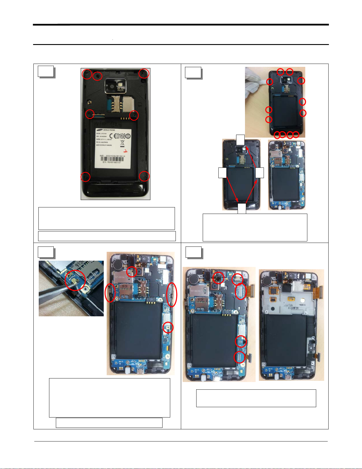
Carefully release the screws at7different locations
from the rear cover.
Torque:
(
1.1±0.1
Be careful not to scratch rear cover.
kgf.cm)(Size: M1.4*L3)
2
4
1
3
2
Disengage the rear cover from
the front cover by using the hook
at12points that colored in red
Follow the numbered sequence
(
when you disjoint)
3
Separate the coaxial cable of antenna
assembly from the PBA.
Release the screw at2points(Size: M1.4*L3)
Torque:
(
Detach the side FPCBs from the Bracket.
1.1±0.1
Be careful not to damage the FPCBs.
kgf.cm)
4
Separate all connector ribbons from the PBA.
Separate the PBA from the Front.
7-1
Confidential and proprietary-the contents in this service guide subject to change without prior notice.
Distribution, transmission, or infringement of any content or data from this document without Samsung’swritten authorization is strictly prohibited.
Level2Repair
7.
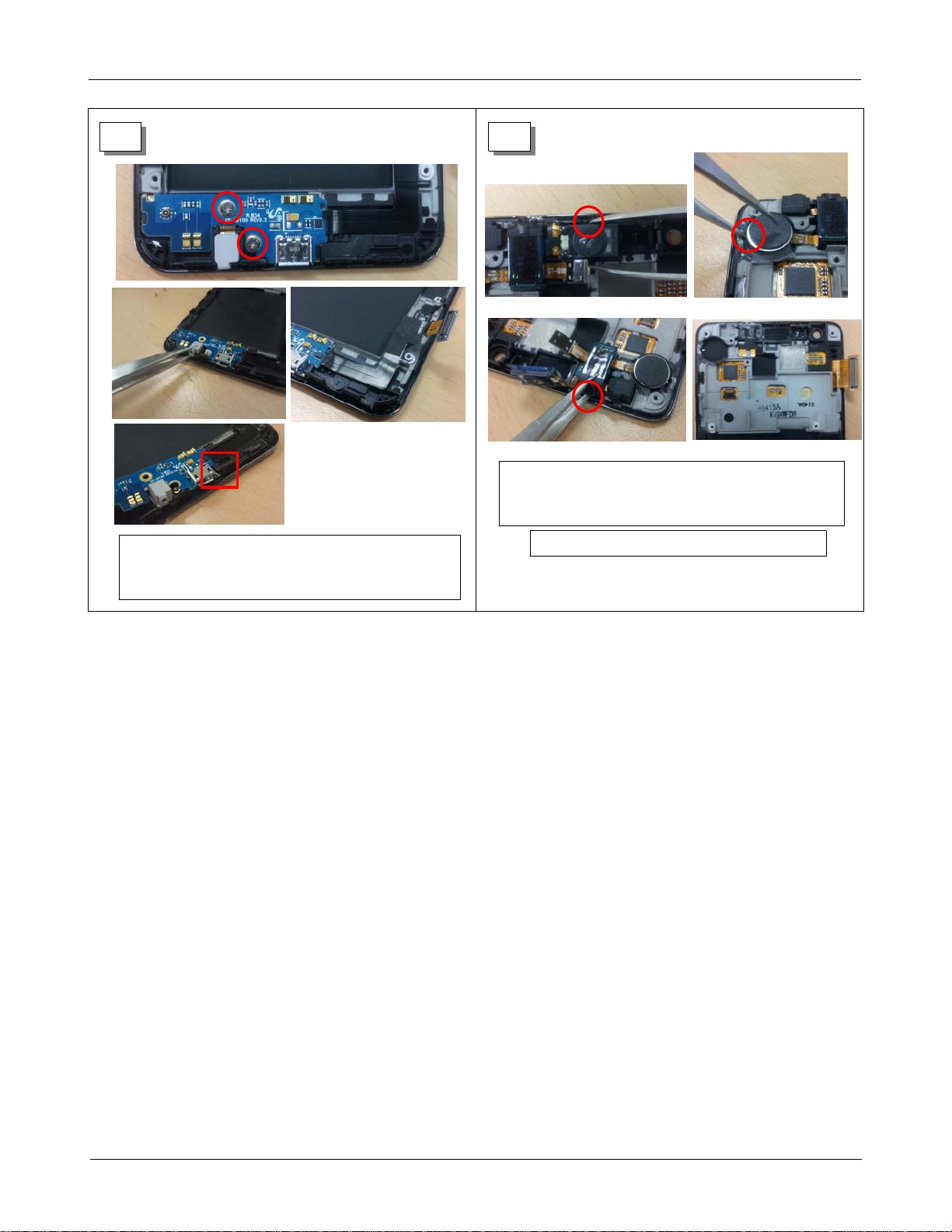
5 6
Separate the Receiver assembly from the Front.
Insertalong nose tweezer into the holes for
(
easy separation.
)
Release the screw at2point
Torque:
(
1.1±0.1
kgf.cm)
Size: M1.4*L2)
s (
Separate the sub PBA from the PBA.
Be careful not to damage the FPCBs.
7-2
Confidential and proprietary-the contents in this service guide subject to change without prior notice.
Distribution, transmission, or infringement of any content or data from this document without Samsung’swritten authorization is strictly prohibited.
 Loading...